Catalyst 6500 Series Switches Installation Guide - Ipland
Catalyst 6500 Series Switches Installation Guide - Ipland Catalyst 6500 Series Switches Installation Guide - Ipland
1 2 3 4 5 6 7 8 9 10 1 1 2 12 3 4 5 6 7 8 9 10 13 1 1 14 2 12 15 3 16 4 17 5 18 6 19 7 20 8 21 9 2 10 13 23 1 1 14 24 2 12 15 3 16 4 17 5 18 6 19 7 20 8 21 9 2 25 10 13 23 26 1 14 24 27 12 15 28 16 29 17 30 18 31 19 32 20 3 21 34 2 25 35 13 23 26 36 14 24 27 15 28 16 29 17 30 18 31 19 32 20 3 21 34 37 2 25 35 38 23 26 1 36 39 24 27 2 40 28 3 41 29 4 42 30 5 43 31 6 4 32 7 45 3 8 46 34 37 9 47 25 35 38 48 1 10 26 36 39 2 1 27 40 3 12 28 41 4 29 42 5 30 43 6 31 4 7 32 45 8 3 46 9 34 37 47 10 35 38 13 48 1 1 36 39 14 2 12 40 15 3 41 16 4 42 17 5 43 18 6 4 19 7 45 20 8 46 21 9 37 47 2 10 13 38 48 23 1 14 39 24 12 15 40 16 41 17 42 18 43 19 4 20 45 21 46 2 47 13 25 23 48 14 26 24 15 27 16 28 17 29 18 30 19 31 20 32 21 3 2 25 34 23 26 35 24 27 36 28 29 30 31 32 3 34 25 37 35 26 38 36 27 39 28 40 29 41 30 42 31 43 32 4 3 45 34 37 46 35 38 47 36 39 48 40 41 42 43 4 45 46 37 47 38 48 39 40 41 42 43 4 45 46 47 48 POWER SUPPLY 1 POWER SUPPLY 2 INPUT FAN OK OK WS-SUP32-GE-3B CATALYST 65 0 SUPERVISOR ENGINE 32 CONSOLE EJECT DISK 0 PORT 1 PORT 2 PORT 3 PORT 4 PORT 5 PORT 6 PORT 7 PORT 8 PORT 9 USB 2.0 FAIL WS-SUP32-GE-3B CATALYST 65 0 SUPERVISOR ENGINE 32 CONSOLE EJECT DISK 0 PORT 1 PORT 2 PORT 3 PORT 4 PORT 5 PORT 6 PORT 7 PORT 8 PORT 9 USB 2.0 INPUT FAN OK OK FAIL Establishing the System Ground Chapter 3 Installing the Switch Figure 3-32 System Ground Location (Catalyst 6509-NEB-A and Catalyst 6509-V-E) System ground connector Grounding lug Wire System ground connectors WS-X6548-GE-TX 1 2 112 1314 2324 2526 3536 3738 4748 STATUS 48 PORT 10/1 0/1 0 BASE-T GE SWITCHING MODULE PHONE WS-X6548-GE-TX 1 2 112 1314 2324 2526 3536 3738 4748 STATUS 48 PORT 10/1 0/1 0 BASE-T GE SWITCHING MODULE PHONE WS-X6548-GE-TX 1 2 112 1314 2324 2526 3536 3738 4748 STATUS 48 PORT 10/1 0/1 0 BASE-T GE SWITCHING MODULE PHONE STATUS SYSTEM ACTIVE PWR MGMT RESET LINK LINK LINK LINK LINK LINK LINK LINK LINK STATUS SYSTEM ACTIVE PWR MGMT RESET LINK LINK LINK LINK LINK LINK LINK LINK LINK WS-X6548-GE-TX 1 2 112 1314 2324 2526 3536 3738 4748 STATUS 48 PORT 10/1 0/1 0 BASE-T GE SWITCHING MODULE PHONE WS-X6548-GE-TX 1 2 112 1314 2324 2526 3536 3738 4748 STATUS 48 PORT 10/1 0/1 0 BASE-T GE SWITCHING MODULE PHONE WS-X6548-GE-TX 1 2 112 1314 2324 2526 3536 3738 4748 STATUS 48 PORT 10/1 0/1 0 BASE-T GE SWITCHING MODULE PHONE WS-X6548-GE-TX 1 2 112 1314 2324 2526 3536 3738 4748 STATUS 48 PORT 10/1 0/1 0 BASE-T GE SWITCHING MODULE PHONE o o 113678 OUTPUT OUTPUT 3-58 Catalyst 6500 Series Switches Installation Guide OL-5781-08
Chapter 3 Installing the Switch Establishing the System Ground Installing the System Ground on an 8700 W Power Supply If you have a Catalyst 6506, Catalyst 6509, or Catalyst 6509-NEB chassis with an 8700 W power supply installed, you must attach the system ground lug to the two system ground studs on the power supply faceplate. The extended depth of the 8700 W power supply blocks access to the system ground pad on the switch chassis. To attach the system ground lug and cable to the power supply ground studs, follow these steps: Step 1 Step 2 Step 3 Step 4 Step 5 Step 6 Step 7 Use a wire-stripping tool to remove approximately 0.75 inch (19 mm) of the covering from the end of the grounding wire. Insert the stripped end of the grounding wire into the open end of the grounding lug. Crimp the grounding wire in the barrel of the grounding lug. Verify that the ground wire is securely attached to the ground lug. Remove the M4 nuts, split-ring washers, flat washers from the two system ground studs on the power supply. Position the grounding lug over the two system ground studs on the 8700 W power supply faceplate. (See Figure 3-33.) Ensure that the grounding lug and the grounding wire will not interfere with other switch hardware or rack equipment. Install one flat washer and one split-ring washer over each system ground stud. Secure the system grounding lug and washers in place with the two M4 nuts. Prepare the other end of the grounding wire, and connect it to an appropriate grounding point in your site to ensure adequate earth ground for the switch. OL-5781-08 Catalyst 6500 Series Switches Installation Guide 3-59
- Page 128 and 129: Installing a Catalyst 6503 or Catal
- Page 130 and 131: CAUTION STATUS LINK CONSOLE LINK LI
- Page 132 and 133: Installing a Catalyst 6504-E Switch
- Page 134 and 135: WS-SUP32-GE-3B CAUTION STATUS LINK
- Page 136 and 137: Installing a Catalyst 6504-E Switch
- Page 138 and 139: WS-X6408 8 PORT GIGABIT ETHERNET WS
- Page 140 and 141: WS-X6408 8 PORT GIGABIT ETHERNET WS
- Page 142 and 143: WS-X6408 WS-X6408 WS-X6224 24 PORT
- Page 144 and 145: WS-X6408 WS-X6408 WS-X6224 24 PORT
- Page 146 and 147: Installing a Catalyst 6509-NEB or C
- Page 148 and 149: 1 2 3 4 5 6 7 8 9 10 1 1 2 12 3 4 5
- Page 150 and 151: 1 2 3 4 5 6 7 8 9 10 1 1 2 12 3 4 5
- Page 152 and 153: WS-C6500-SFM SWITCH FABRIC MDL WS-C
- Page 154 and 155: WS-C6500-SFM SWITCH FABRIC MDL WS-C
- Page 156 and 157: Installing a Catalyst 6509-V-E Swit
- Page 158 and 159: Installing a Catalyst 6509-V-E Swit
- Page 160 and 161: Installing a Catalyst 6509-V-E Swit
- Page 162 and 163: Installing a Catalyst 6513 or Catal
- Page 164 and 165: WS-X6408 8 PORT GIGABIT ETHERNET WS
- Page 166 and 167: WS-X6K-SUP2-2GE SUPERVISOR2 WS-X6K-
- Page 168 and 169: Generic Installation Procedures Cha
- Page 170 and 171: Generic Installation Procedures Cha
- Page 172 and 173: Establishing the System Ground Chap
- Page 174 and 175: OSM-4OC12 POS-SI 2 1 2 1 4 2 3 1 4
- Page 176 and 177: WS-X6K-SUP2-2GE SUPERVISOR2 WS-X6K-
- Page 180 and 181: Establishing the System Ground Chap
- Page 182 and 183: Attaching the Interface Cables Chap
- Page 184 and 185: Attaching the Interface Cables Chap
- Page 186 and 187: Attaching the Interface Cables Chap
- Page 188 and 189: Attaching the Interface Cables Chap
- Page 190 and 191: Attaching the Interface Cables Chap
- Page 192 and 193: LINK Attaching the Interface Cables
- Page 194 and 195: LINK Attaching the Interface Cables
- Page 196 and 197: Attaching the Interface Cables Chap
- Page 198 and 199: Attaching the Interface Cables Chap
- Page 200 and 201: Attaching the Interface Cables Chap
- Page 202 and 203: Attaching the Interface Cables Chap
- Page 204 and 205: Verifying Switch Chassis Installati
- Page 206 and 207: Verifying Switch Chassis Installati
- Page 208 and 209: Removing and Installing the AC-Inpu
- Page 210 and 211: OSM-4OC12 POS-SI 2 1 2 1 4 2 3 1 4
- Page 212 and 213: Removing and Installing the AC-Inpu
- Page 214 and 215: ALL FASTENERS MUST BE FULLY ENGAGED
- Page 216 and 217: Removing and Installing the AC-Inpu
- Page 218 and 219: WS-X6K-SUP2-2GE SUPERVISOR2 WS-X6K-
- Page 220 and 221: Removing and Installing the AC-Inpu
- Page 222 and 223: OSM-4OC12 POS-SI 1 2 1 2 1 1 2 2 3
- Page 224 and 225: Removing and Installing the DC-Inpu
- Page 226 and 227: Removing and Installing the DC-Inpu
1<br />
2<br />
3<br />
4<br />
5<br />
6<br />
7<br />
8<br />
9<br />
10<br />
1<br />
1<br />
2<br />
12<br />
3<br />
4<br />
5<br />
6<br />
7<br />
8<br />
9<br />
10<br />
13<br />
1<br />
1<br />
14<br />
2<br />
12<br />
15<br />
3<br />
16<br />
4<br />
17<br />
5<br />
18<br />
6<br />
19<br />
7<br />
20<br />
8<br />
21<br />
9<br />
2<br />
10<br />
13<br />
23<br />
1<br />
1<br />
14<br />
24<br />
2<br />
12<br />
15<br />
3<br />
16<br />
4<br />
17<br />
5<br />
18<br />
6<br />
19<br />
7<br />
20<br />
8<br />
21<br />
9<br />
2<br />
25<br />
10<br />
13<br />
23<br />
26<br />
1<br />
14<br />
24<br />
27<br />
12<br />
15<br />
28<br />
16<br />
29<br />
17<br />
30<br />
18<br />
31<br />
19<br />
32<br />
20<br />
3<br />
21<br />
34<br />
2<br />
25<br />
35<br />
13<br />
23<br />
26<br />
36<br />
14<br />
24<br />
27<br />
15<br />
28<br />
16<br />
29<br />
17<br />
30<br />
18<br />
31<br />
19<br />
32<br />
20<br />
3<br />
21<br />
34<br />
37<br />
2<br />
25<br />
35<br />
38<br />
23<br />
26<br />
1<br />
36<br />
39<br />
24<br />
27<br />
2<br />
40<br />
28<br />
3<br />
41<br />
29<br />
4<br />
42<br />
30<br />
5<br />
43<br />
31<br />
6<br />
4<br />
32<br />
7<br />
45<br />
3<br />
8<br />
46<br />
34<br />
37<br />
9<br />
47<br />
25<br />
35<br />
38<br />
48<br />
1<br />
10<br />
26<br />
36<br />
39<br />
2<br />
1<br />
27<br />
40<br />
3<br />
12<br />
28<br />
41<br />
4<br />
29<br />
42<br />
5<br />
30<br />
43<br />
6<br />
31<br />
4<br />
7<br />
32<br />
45<br />
8<br />
3<br />
46<br />
9<br />
34<br />
37<br />
47<br />
10<br />
35<br />
38<br />
13<br />
48<br />
1<br />
1<br />
36<br />
39<br />
14<br />
2<br />
12<br />
40<br />
15<br />
3<br />
41<br />
16<br />
4<br />
42<br />
17<br />
5<br />
43<br />
18<br />
6<br />
4<br />
19<br />
7<br />
45<br />
20<br />
8<br />
46<br />
21<br />
9<br />
37<br />
47<br />
2<br />
10<br />
13<br />
38<br />
48<br />
23<br />
1<br />
14<br />
39<br />
24<br />
12<br />
15<br />
40<br />
16<br />
41<br />
17<br />
42<br />
18<br />
43<br />
19<br />
4<br />
20<br />
45<br />
21<br />
46<br />
2<br />
47<br />
13<br />
25<br />
23<br />
48<br />
14<br />
26<br />
24<br />
15<br />
27<br />
16<br />
28<br />
17<br />
29<br />
18<br />
30<br />
19<br />
31<br />
20<br />
32<br />
21<br />
3<br />
2<br />
25<br />
34<br />
23<br />
26<br />
35<br />
24<br />
27<br />
36<br />
28<br />
29<br />
30<br />
31<br />
32<br />
3<br />
34<br />
25<br />
37<br />
35<br />
26<br />
38<br />
36<br />
27<br />
39<br />
28<br />
40<br />
29<br />
41<br />
30<br />
42<br />
31<br />
43<br />
32<br />
4<br />
3<br />
45<br />
34<br />
37<br />
46<br />
35<br />
38<br />
47<br />
36<br />
39<br />
48<br />
40<br />
41<br />
42<br />
43<br />
4<br />
45<br />
46<br />
37<br />
47<br />
38<br />
48<br />
39<br />
40<br />
41<br />
42<br />
43<br />
4<br />
45<br />
46<br />
47<br />
48<br />
POWER SUPPLY 1 POWER SUPPLY 2<br />
INPUT FAN<br />
OK OK<br />
WS-SUP32-GE-3B<br />
CATALYST 65 0 SUPERVISOR ENGINE 32<br />
CONSOLE<br />
EJECT<br />
DISK 0 PORT 1 PORT 2 PORT 3 PORT 4 PORT 5 PORT 6 PORT 7 PORT 8<br />
PORT 9<br />
USB 2.0<br />
FAIL<br />
WS-SUP32-GE-3B<br />
CATALYST 65 0 SUPERVISOR ENGINE 32<br />
CONSOLE<br />
EJECT<br />
DISK 0 PORT 1 PORT 2 PORT 3 PORT 4 PORT 5 PORT 6 PORT 7 PORT 8<br />
PORT 9<br />
USB 2.0<br />
INPUT FAN<br />
OK OK<br />
FAIL<br />
Establishing the System Ground<br />
Chapter 3<br />
Installing the Switch<br />
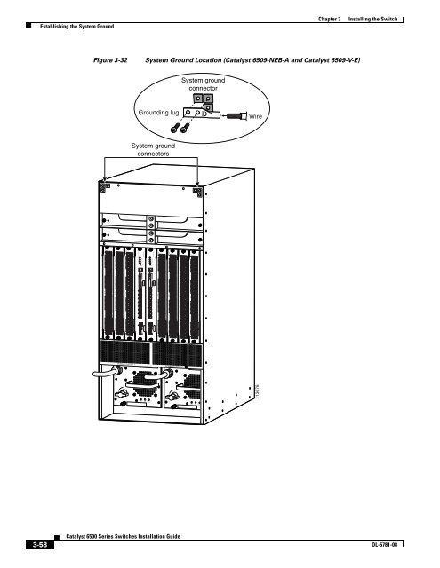
Figure 3-32<br />
System Ground Location (<strong>Catalyst</strong> 6509-NEB-A and <strong>Catalyst</strong> 6509-V-E)<br />
System ground<br />
connector<br />
Grounding lug<br />
Wire<br />
System ground<br />
connectors<br />
WS-X6548-GE-TX<br />
1<br />
2<br />
112 1314 2324 2526 3536 3738 4748<br />
STATUS 48 PORT 10/1 0/1 0<br />
BASE-T GE<br />
SWITCHING MODULE<br />
PHONE<br />
WS-X6548-GE-TX<br />
1<br />
2<br />
112 1314 2324 2526 3536 3738 4748<br />
STATUS 48 PORT 10/1 0/1 0<br />
BASE-T GE<br />
SWITCHING MODULE<br />
PHONE<br />
WS-X6548-GE-TX<br />
1<br />
2<br />
112 1314 2324 2526 3536 3738 4748<br />
STATUS 48 PORT 10/1 0/1 0<br />
BASE-T GE<br />
SWITCHING MODULE<br />
PHONE<br />
STATUS<br />
SYSTEM<br />
ACTIVE<br />
PWR MGMT<br />
RESET<br />
LINK<br />
LINK<br />
LINK<br />
LINK<br />
LINK<br />
LINK<br />
LINK<br />
LINK<br />
LINK<br />
STATUS<br />
SYSTEM<br />
ACTIVE<br />
PWR MGMT<br />
RESET<br />
LINK<br />
LINK<br />
LINK<br />
LINK<br />
LINK<br />
LINK<br />
LINK<br />
LINK<br />
LINK<br />
WS-X6548-GE-TX<br />
1<br />
2<br />
112 1314 2324 2526 3536 3738 4748<br />
STATUS 48 PORT 10/1 0/1 0<br />
BASE-T GE<br />
SWITCHING MODULE<br />
PHONE<br />
WS-X6548-GE-TX<br />
1<br />
2<br />
112 1314 2324 2526 3536 3738 4748<br />
STATUS 48 PORT 10/1 0/1 0<br />
BASE-T GE<br />
SWITCHING MODULE<br />
PHONE<br />
WS-X6548-GE-TX<br />
1<br />
2<br />
112 1314 2324 2526 3536 3738 4748<br />
STATUS 48 PORT 10/1 0/1 0<br />
BASE-T GE<br />
SWITCHING MODULE<br />
PHONE<br />
WS-X6548-GE-TX<br />
1<br />
2<br />
112 1314 2324 2526 3536 3738 4748<br />
STATUS 48 PORT 10/1 0/1 0<br />
BASE-T GE<br />
SWITCHING MODULE<br />
PHONE<br />
o<br />
o<br />
113678<br />
OUTPUT<br />
OUTPUT<br />
3-58<br />
<strong>Catalyst</strong> <strong>6500</strong> <strong>Series</strong> <strong>Switches</strong> <strong>Installation</strong> <strong>Guide</strong><br />
OL-5781-08


