Catalyst 6500 Series Switches Installation Guide - Ipland
Catalyst 6500 Series Switches Installation Guide - Ipland Catalyst 6500 Series Switches Installation Guide - Ipland
WS-C6500-SFM SWITCH FABRIC MDL WS-C6500-SFM SWITCH FABRIC MDL Installing a Catalyst 6509-NEB or Catalyst 6509-NEB-A Switch Chassis Chapter 3 Installing the Switch Step 3 Loosen the two captive installation screws on the front panel. (See Figure 3-15.) Figure 3-15 Removing the Front Panel FAN STATUS 99970 FAN 1 FAN 2 OSM-8OC3-POS MM 8 PORT OC3 POS MM 8 PORT OC3 POS STATUS OSM-8OC3-POS MM STATUS OC12 POS MM STATUS OSM-40C12-POS-MM STAT STATUS OC12 POS MM STATUS OSM-40C12-POS-MM OC12 POS MM STATUS OSM-40C12-POS-MM SUPERVISOR2 STATUS SYSTEM WS-X6K-SUP2-2GE SUPERVISOR2 STATUS SYSTEM WS-X6K-SUP2-2GE Captive installation screws Step 4 Remove the front panel, and set it aside. Step 5 Attach the interface cables to the modules, and route the cables through the cable guide. Step 6 Install the front panel by positioning the top of the front panel over the cable guide. Step 7 Tighten the two captive installation screws. (See Figure 3-15.) 3-32 Catalyst 6500 Series Switches Installation Guide OL-5781-08
WS-C6500-SFM SWITCH FABRIC MDL WS-C6500-SFM SWITCH FABRIC MDL WS-C6500-SFM SWITCH FABRIC MDL WS-C6500-SFM SWITCH FABRIC MDL Chapter 3 Installing the Switch Installing a Catalyst 6509-NEB or Catalyst 6509-NEB-A Switch Chassis Replacing the Cable Guide To replace the cable guides on the cable management system, perform these steps: Step 1 Loosen the two captive installation screws on the front panel. (See Figure 3-16.) Figure 3-16 Removing the Front Panel FAN STATUS 99970 FAN 1 FAN 2 OSM-8OC3-POS MM 8 PORT OC3 POS MM 8 PORT OC3 POS STATUS OSM-8OC3-POS MM STATUS OC12 POS MM STATUS OSM-40C12-POS-MM STAT STATUS OC12 POS MM STATUS OSM-40C12-POS-MM OC12 POS MM STATUS OSM-40C12-POS-MM SUPERVISOR2 STATUS SYSTEM WS-X6K-SUP2-2GE SUPERVISOR2 STATUS SYSTEM WS-X6K-SUP2-2GE Captive installation screws Step 2 Step 3 Remove the front panel, and set it aside. Remove the two screws that secure the cable guide to the back panel, and remove the cable guide by lifting it up and away from the back panel. (See Figure 3-17.) Figure 3-17 Removing the Cable Guide FAN STATUS 85431 FAN 1 FAN 2 OSM-8OC3-POS MM 8 PORT OC3 POS MM 8 PORT OC3 POS STATUS OSM-8OC3-POS MM STATUS OC12 POS MM STATUS OSM-40C12-POS-MM STAT STATUS OC12 POS MM STATUS OSM-40C12-POS-MM OC12 POS MM STATUS OSM-40C12-POS-MM SUPERVISOR2 STATUS SYSTEM WS-X6K-SUP2-2GE SUPERVISOR2 STATUS SYSTEM WS-X6K-SUP2-2GE OL-5781-08 Catalyst 6500 Series Switches Installation Guide 3-33
- Page 102 and 103: WS-X6K-SUP2-2GE SUPERVISOR2 WS-X6K-
- Page 104 and 105: WS-X6K-SUP2-2GE SUPERVISOR2 WS-X6K-
- Page 106 and 107: 1 2 3 4 5 6 7 8 9 10 1 1 2 12 3 4 5
- Page 108 and 109: WS-X6408 8 PORT GIGABIT ETHERNET WS
- Page 110 and 111: Site Requirements Chapter 2 Prepari
- Page 112 and 113: Site Requirements Chapter 2 Prepari
- Page 114 and 115: Site Requirements Chapter 2 Prepari
- Page 116 and 117: Power Requirements Chapter 2 Prepar
- Page 118 and 119: Cabling Requirements Chapter 2 Prep
- Page 120 and 121: Site Preparation Checklist Chapter
- Page 122 and 123: Chapter 3 Installing the Switch The
- Page 124 and 125: Rack-Mounting Guidelines Chapter 3
- Page 126 and 127: Chassis Installation Kits and Cable
- Page 128 and 129: Installing a Catalyst 6503 or Catal
- Page 130 and 131: CAUTION STATUS LINK CONSOLE LINK LI
- Page 132 and 133: Installing a Catalyst 6504-E Switch
- Page 134 and 135: WS-SUP32-GE-3B CAUTION STATUS LINK
- Page 136 and 137: Installing a Catalyst 6504-E Switch
- Page 138 and 139: WS-X6408 8 PORT GIGABIT ETHERNET WS
- Page 140 and 141: WS-X6408 8 PORT GIGABIT ETHERNET WS
- Page 142 and 143: WS-X6408 WS-X6408 WS-X6224 24 PORT
- Page 144 and 145: WS-X6408 WS-X6408 WS-X6224 24 PORT
- Page 146 and 147: Installing a Catalyst 6509-NEB or C
- Page 148 and 149: 1 2 3 4 5 6 7 8 9 10 1 1 2 12 3 4 5
- Page 150 and 151: 1 2 3 4 5 6 7 8 9 10 1 1 2 12 3 4 5
- Page 154 and 155: WS-C6500-SFM SWITCH FABRIC MDL WS-C
- Page 156 and 157: Installing a Catalyst 6509-V-E Swit
- Page 158 and 159: Installing a Catalyst 6509-V-E Swit
- Page 160 and 161: Installing a Catalyst 6509-V-E Swit
- Page 162 and 163: Installing a Catalyst 6513 or Catal
- Page 164 and 165: WS-X6408 8 PORT GIGABIT ETHERNET WS
- Page 166 and 167: WS-X6K-SUP2-2GE SUPERVISOR2 WS-X6K-
- Page 168 and 169: Generic Installation Procedures Cha
- Page 170 and 171: Generic Installation Procedures Cha
- Page 172 and 173: Establishing the System Ground Chap
- Page 174 and 175: OSM-4OC12 POS-SI 2 1 2 1 4 2 3 1 4
- Page 176 and 177: WS-X6K-SUP2-2GE SUPERVISOR2 WS-X6K-
- Page 178 and 179: 1 2 3 4 5 6 7 8 9 10 1 1 2 12 3 4 5
- Page 180 and 181: Establishing the System Ground Chap
- Page 182 and 183: Attaching the Interface Cables Chap
- Page 184 and 185: Attaching the Interface Cables Chap
- Page 186 and 187: Attaching the Interface Cables Chap
- Page 188 and 189: Attaching the Interface Cables Chap
- Page 190 and 191: Attaching the Interface Cables Chap
- Page 192 and 193: LINK Attaching the Interface Cables
- Page 194 and 195: LINK Attaching the Interface Cables
- Page 196 and 197: Attaching the Interface Cables Chap
- Page 198 and 199: Attaching the Interface Cables Chap
- Page 200 and 201: Attaching the Interface Cables Chap
WS-C<strong>6500</strong>-SFM<br />
SWITCH FABRIC MDL<br />
WS-C<strong>6500</strong>-SFM<br />
SWITCH FABRIC MDL<br />
Installing a <strong>Catalyst</strong> 6509-NEB or <strong>Catalyst</strong> 6509-NEB-A Switch Chassis<br />
Chapter 3<br />
Installing the Switch<br />
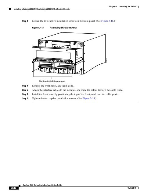
Step 3 Loosen the two captive installation screws on the front panel. (See Figure 3-15.)<br />
Figure 3-15<br />
Removing the Front Panel<br />
FAN<br />
STATUS<br />
99970<br />
FAN 1<br />
FAN 2<br />
OSM-8OC3-POS MM<br />
8 PORT OC3 POS MM<br />
8 PORT OC3 POS<br />
STATUS<br />
OSM-8OC3-POS MM<br />
STATUS<br />
OC12 POS MM<br />
STATUS<br />
OSM-40C12-POS-MM<br />
STAT<br />
STATUS<br />
OC12 POS MM<br />
STATUS<br />
OSM-40C12-POS-MM<br />
OC12 POS MM<br />
STATUS<br />
OSM-40C12-POS-MM<br />
SUPERVISOR2<br />
STATUS<br />
SYSTEM<br />
WS-X6K-SUP2-2GE<br />
SUPERVISOR2<br />
STATUS<br />
SYSTEM<br />
WS-X6K-SUP2-2GE<br />
Captive installation screws<br />
Step 4 Remove the front panel, and set it aside.<br />
Step 5 Attach the interface cables to the modules, and route the cables through the cable guide.<br />
Step 6 Install the front panel by positioning the top of the front panel over the cable guide.<br />
Step 7 Tighten the two captive installation screws. (See Figure 3-15.)<br />
3-32<br />
<strong>Catalyst</strong> <strong>6500</strong> <strong>Series</strong> <strong>Switches</strong> <strong>Installation</strong> <strong>Guide</strong><br />
OL-5781-08


