SmartJoist Installation Guide 2012 - Tilling Timber
SmartJoist Installation Guide 2012 - Tilling Timber
SmartJoist Installation Guide 2012 - Tilling Timber

Create successful ePaper yourself
Turn your PDF publications into a flip-book with our unique Google optimized e-Paper software.
May <strong>2012</strong><br />
NSW OFFICE QLD OFFICE WA OFFICE<br />
109 Kurrajong Avenue 20-24 Nealdon Drive 10 Cartwright Drive<br />
Mt Druitt NSW 2770 Meadowbrook QLD 4131 Forestdale WA 6090<br />
Tel: 02 9677 2600 Tel: 07 3440 5400 Tel: 08 9248 7643<br />
Fax: 02 9677 2500 Tel: 07 3440 5444 Fax: 08 9248 3241<br />
<strong>Tilling</strong> <strong>Timber</strong> Pty Ltd - Head Office 31 - 45 Orchard Street KILSYTH 3137<br />
Ph: 03 9725 0222 Fax: 03 9725 6569 Web: www.tilling.com.au e-mail: smartdata@tilling.com.au<br />
<strong>SmartJoist</strong> INSTALLATION GUIDE<br />
GENERAL<br />
Jobsite handling and storage, erection procedure and erection<br />
bracing are the responsibility of the installer. Careful<br />
review of this installation guide, project plans and joist layout<br />
drawings (where supplied) should be undertaken prior to the<br />
installation of the joists. The manufacturers warranty applies<br />
only to properly installed undamaged joists, adequately protected<br />
from the weather in the completed project.<br />
<strong>SmartJoist</strong> SIZES<br />
34<br />
200<br />
34<br />
34 34 34 34<br />
240 240 240 240<br />
300<br />
44 40 51 70 90<br />
40<br />
SJ20044 SJ24040 SJ24051 SJ24070 SJ24090<br />
SJ30040<br />
34<br />
38<br />
34<br />
300<br />
34<br />
300<br />
34<br />
300<br />
34<br />
360<br />
360<br />
400<br />
51<br />
70<br />
90<br />
58<br />
90<br />
90<br />
SJ30051<br />
SJ30070<br />
SJ30090<br />
SJ36058<br />
SJ36090<br />
SJ40090<br />
SAFETY WARNING<br />
DO NOT ALLOW WORKERS OR LOADS<br />
ON <strong>SmartJoist</strong>s UNTIL ALL BLOCKING,<br />
HANGERS, RIM JOISTS, NAILING AND<br />
TEMPORARY BRACING ARE IN-<br />
STALLED AS SPECIFIED.<br />
SERIOUS ACCIDENTS OR INJURY CAN<br />
RESULT FROM FAILURE TO FOLLOW<br />
THESE GUIDELINES.<br />
<strong>SmartJoist</strong> <strong>Installation</strong> <strong>Guide</strong> May <strong>2012</strong> 1
SAFETY WARNING<br />
DO NOT ALLOW WORKERS OR LOADS ON<br />
<strong>SmartJoist</strong>s UNTIL ALL BLOCKING, HANG-<br />
ERS, RIM JOISTS, NAILING AND TEMPO-<br />
RARY BRACING ARE INSTALLED AS SPECI-<br />
FIED BELOW. SERIOUS ACCIDENTS OR IN-<br />
JURY CAN RESULT FROM FAILURE TO FOL-<br />
LOW THESE GUIDELINES.<br />
ACCIDENTS CAN BE AVOIDED UNDER NORMAL CONDITIONS BY FOLLOWING THESE GUIDELINES:<br />
1. Brace each joist as it is erected. Joists must be<br />
nailed to supports and all hangers, blocking, rim<br />
joists. X - bridging at supports must be completely<br />
installed and properly nailed. (see general notes<br />
and details - page 5)<br />
2. Brace the ends of cantilevers (overhangs) with<br />
closure panels, rim joist or x - bridging (see general<br />
notes and details - page 5)<br />
3. Lateral brace the top flange of each joist, to prevent<br />
sideways buckling or rollover which may occur<br />
under light construction loads, such as a worker<br />
and/or a layer of un-nailed sheathing. Fully installed<br />
permanent sheathing or temporary struts<br />
to the top flange of each joist (see ‘typical<br />
<strong>SmartJoist</strong> floor framing - page 6) can accomplish<br />
lateral bracing.<br />
4. Temporary struts must be nailed to a lateral restraint<br />
at the end of bay such as a braced wall or<br />
temporary (or permanent) sheathing nailed to the<br />
first 1200 mm of the joist at the end of the bay<br />
(see typical floor or roof framing - page 6)<br />
5. Permanent sheathing must be completely installed<br />
and properly nailed before additional loads can be<br />
placed on the system.<br />
6. The integrity and safe use of these products can<br />
be seriously impaired if they are damaged. Do<br />
not install any damaged products. Contact your<br />
<strong>Tilling</strong> representative or the SmartData Customer<br />
HelpLine on 1300 668 690 if any product<br />
damage is noted.<br />
HANDLING AND STORAGE OF <strong>SmartJoist</strong>s<br />
<strong>SmartJoist</strong>s should be stacked in the upright position to avoid any damage during handling or storage.<br />
<br />
Bearers at a maximum of<br />
4.0 metre centres<br />
<br />
Use bearers to keep stacked material away from damp surfaces.<br />
<strong>SmartJoist</strong> <strong>Installation</strong> <strong>Guide</strong> May <strong>2012</strong> 2
SAFE LOADING OF MATERIALS ON A WORKING PLATFORM<br />
IMPORTANT!! Joists must be fully braced of have floor sheeting<br />
installed before applying any of the following loads.<br />
* 200 kg per joist for joists less than 240 mm deep<br />
* 250 kg per joist for joists 240 mm and greater<br />
1000 max<br />
Max<br />
200/250* kg<br />
per joist<br />
Max<br />
200/250* kg<br />
1000 min per joist<br />
1000 max<br />
1600 max<br />
1600 max<br />
Maximum distance to centre of load from face of support = 1600 mm.<br />
Maximum of 2 loads can be applied to 1 joist length, providing they are not more than<br />
1600 mm from the face of the wall and a minimum of 1000 mm between loads as<br />
shown.<br />
1600 max<br />
1600 max<br />
600<br />
1000 min<br />
600<br />
600<br />
1000 max 1200<br />
1200 1000 max<br />
600<br />
600<br />
Joist direction<br />
600<br />
600<br />
600<br />
600<br />
No materials stacked<br />
in this area !<br />
Stair<br />
opening<br />
600<br />
Notes:<br />
1. Deflection limit is taken as span/200<br />
2. All timber must be kept dry when applying maximum temporary loading<br />
3. Loads are to be spread equally over a minimum of 2 joists, using timber bearers at a minimum of 1200 mm in length or a<br />
standard 1200 x 1200 pallet<br />
4. NO loads are to be stacked over any part of the lengths of the joists fixed to an opening header or trimmer joist such as a stair<br />
trimmer<br />
5. If no plasterboard is in place under the joists, the bottom flange requires temporary bracing<br />
6. Joists on hangers may require propping<br />
7. If unsure about stacking concentrated loads on <strong>SmartJoist</strong> working platforms, please contact the SmartFrame Design Centre<br />
on 1300 668 690.<br />
<strong>SmartJoist</strong> <strong>Installation</strong> <strong>Guide</strong> May <strong>2012</strong> 3
DURABILITY AND EXPOSURE TO MOISTURE<br />
- Untreated SmartFrame EWP<br />
SmartLVL and <strong>SmartJoist</strong>s are manufactured from Douglas Fir<br />
(Oregon) which has a durability rating of class 4, which is the<br />
same rating as some Ash type Eucalypts. Untreated<br />
<strong>SmartJoist</strong>s and SmartLVL should not be used where the equilibrium<br />
moisture content is likely to remain above 20% for an<br />
extended period.<br />
Untreated SmartLVL is suitable in the internal, fully protected,<br />
ventilated and the external above ground, protected zones of<br />
the structure as shown on the next page. Untreated SmartLVL<br />
is not suitable for external above ground, exposed or humid<br />
indoor conditions, such as swimming pool enclosures.<br />
External,<br />
above ground,<br />
exposed<br />
Internal, fully<br />
protected,<br />
ventilated<br />
DEFINITIONS OF EXPOSURE ZONES<br />
WITHIN A STRUCTURE<br />
30°<br />
* External timbers are regarded as protected<br />
in AS 1684 if they are covered by a roof projection<br />
(or similar) at 30° to the vertical and they<br />
are well detailed and maintained (painted and<br />
kept well ventilated).<br />
External,<br />
above ground,<br />
protected. *<br />
SMARTGUARD H3 DECK BEARERS AND JOISTS<br />
SmartGuard H3 Treated Deck joists and bearers are a common application for treated SmartLVL 15. The diagram demonstrates the<br />
minimum construction detailing for SmartGuard LOSP H3 treated joists and bearers. Failure to follow these guidelines may render<br />
treatment warranties void.<br />
H3 treated or naturally durable species decking.<br />
(LOSP treatment is NOT recommended for<br />
decking members)<br />
Protectadeck or malthoid waterproof<br />
capping to prevent water ponding on<br />
SmartGuard H3 treated joists and bearers.<br />
SmartGuard H3 treated and painted* LVL<br />
external deck joists and bearers.<br />
Recommended proprietary top<br />
protection for joists and bearers<br />
H3 treated or Natural Durability<br />
class 1 or 2 (sapwood removed)<br />
decking<br />
It is a requirement that any cuts, notches<br />
or penetrations made in LOSP treated<br />
LVL be painted with a suitable “brush/<br />
spray on” preservative such as “Enseal”.<br />
(Enseal is available as part of any Smart-<br />
Frame H3 LOSP order)<br />
* Painting as per “Painting of SmartGuard LOSP Treated SmartLVL 15” in the SmartLVL 15<br />
Design <strong>Guide</strong><br />
Protectadeck or<br />
similar impervious<br />
membrane to<br />
prevent water<br />
ponding on joist<br />
Skew deck<br />
nails slightly<br />
to cross<br />
multiple veneers<br />
(Galvanised helical<br />
threaded nails or<br />
screws)<br />
H3 treated<br />
SmartLVL<br />
joists<br />
Recommended Fastening to<br />
SmartLVL Deck Joists.<br />
<strong>SmartJoist</strong> <strong>Installation</strong> <strong>Guide</strong> May <strong>2012</strong> 4
<strong>SmartJoist</strong>s - GENERAL NOTES<br />
Do NOT start toe nail<br />
into the corner of the flange<br />
or the top of the flange.<br />
MAXIMUM Nail diameter 3.15 mm<br />
<br />
<br />
Nails should be as far<br />
as practical from the<br />
end of the joist<br />
Start toe nail<br />
approximately 2/3<br />
up the side of the flange.<br />
1. Except where otherwise noted, 30 mm minimum<br />
bearing is required at joist ends and 42 mm minimum<br />
bearing is required at intermediate supports.<br />
2. Nail joists at each bearing with 2 of 3.15 Ф x 65<br />
nails, using one each side placed 30 mm from the<br />
end to avoid splitting.<br />
3. <strong>SmartJoist</strong> blocking or Rimboard - face nail to bearing<br />
plate with 3.15 Ф x 65 nails at 150 mm centres.<br />
Nail rim joist to the end of the top and bottom<br />
flange of each <strong>SmartJoist</strong> with 1 3.15 Ф x 65 nail,<br />
use 1 3.75 Ф x 75 nail top and bottom with joists<br />
with 58 or 90 mm wide flanges.<br />
4. SmartRim - toe nail to bearing plate with 3.15 Ф x<br />
65 nails at 150 centres or 4.5 Ф x 75 nails at 300<br />
centres. Nail rim to the end of the top and bottom<br />
flanges of each <strong>SmartJoist</strong> with 1 3.15 Ф x 65 nails.<br />
5. Sheathing nailing to top flange (Joists must be fully<br />
braced before sheathing is nailed)<br />
- Space 2.8 Ф x 65 and 3.15 Ф x 65 nails no<br />
closer than 50 mm per row.<br />
- Space 3.75 x 75 nails no closer than 75 mm.<br />
Maximum nail spacing: 300 mm<br />
6. Backer blocks at hanger details:<br />
40 mm flanges - 15 mm ply<br />
44 & 51 mm flange - 19 mm ply<br />
58 mm flange - 2 pieces of 12 mm ply<br />
70 mm flange - 2 pieces of 15 mm ply<br />
90 mm flange - 2 pieces of 19 mm ply<br />
7. See double <strong>SmartJoist</strong> detail F15 for filler blocks.<br />
Nail Joists together with two rows of 3.75 Ф x 75<br />
nails on each side of double joist at 300 mm centres<br />
(Clinch if possible). A total of 4 nails per 300<br />
mm is required. If nails can be clinched, only 2 nails<br />
per 300 mm is required.<br />
8. All joists require lateral support at end bearings<br />
using blocking or rim material.<br />
9. The top flanges must be kept straight within 10 mm<br />
of the true alignment.<br />
10. See web stiffener detail F13 for web stiffener attachment<br />
at supports. Web stiffener requirements for<br />
concentrated loads in excess of 4.5 kN, applied at<br />
the top flange of the joist, requires additional consideration.<br />
11. When required, install web stiffeners to joist (see<br />
detail F13) prior to placing joist in the hanger, then<br />
nail hanger to joist.<br />
12. All roof details are valid to a maximum angle of 35°<br />
(as per AS1684 - 1999)<br />
13. All nails are steel nails complying with AS 2334 -<br />
1980 Steel nails - Metric series. Nail gun nails of<br />
similar length and diameter may be substituted for<br />
the above provided that they are manufactured with<br />
properties equivalent to the nails in the above code.<br />
14. Install all hangers to the manufacturers installation<br />
instructions, taking particular attention to the use of<br />
the correct nails. Never use clouts or brads.<br />
15. Prescriptive code requirements for mid span blocking<br />
of solid timber joists are not applicable to<br />
<strong>SmartJoist</strong>s.<br />
END BLOCKING AND <strong>SmartJoist</strong><br />
The end blocking of I-Joists performs three (3) essential<br />
functions, as well as being an invaluable component of the<br />
bracing of the structure as a whole unit. These functions<br />
include:<br />
(1) Keeps joists upright and prevents rollover during<br />
construction<br />
(2) Provides end reaction capacity to the I-Joists and<br />
(3) Provides extra torsional resistance to the I-Joist to<br />
improve floor performance.<br />
(A full description of the end blocking effects is contained in<br />
the <strong>SmartJoist</strong> Design <strong>Guide</strong>).<br />
The <strong>SmartJoist</strong> floor joists should be fully blocked at their<br />
end bearing points onto exterior load bearing walls as<br />
shown in the blocking options following.<br />
<strong>SmartJoist</strong> <strong>Installation</strong> <strong>Guide</strong> May <strong>2012</strong> 5
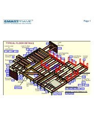
TYPICAL <strong>SmartJoist</strong> FLOOR FRAMING<br />
F7 or F8<br />
<strong>SmartJoist</strong> blocking panel or full depth cripple on each<br />
side required when supporting load bearing walls above.<br />
Non<br />
load-bearing<br />
cantilever<br />
F9<br />
Blocking panels<br />
required when<br />
<strong>SmartJoist</strong>s are<br />
cantilevered<br />
F2<br />
<strong>SmartJoist</strong> rim joist<br />
Hole sizes and locations<br />
as per hole charts<br />
C1 or C2<br />
Load bearing cantilever<br />
F1<br />
&<br />
F5<br />
Smart<br />
Joist<br />
Blocking<br />
F15<br />
Approved joist<br />
hanger<br />
F12<br />
Standard<br />
connection<br />
of I-Joist to<br />
I-Joists<br />
Multiple<br />
<strong>SmartJoist</strong>s<br />
Solid timber<br />
or LVL Beam<br />
F3<br />
& F4<br />
SmartRim<br />
Rimboard<br />
F11<br />
Standard connection of<br />
<strong>SmartJoist</strong> to solid<br />
timber or LVL beam.<br />
Temporary floor sheeting if end wall is<br />
not braced. Attach with 3.15 mm dia<br />
nails at 150 mm centres Max. Keep in<br />
position until permanent sheeting is<br />
installed. (see #2 of SAFETY WARNING)<br />
Temporary struts at 2400 mm centres.<br />
Nail struts to each joist with 2 of 3.15 mm diam x 65 nails.<br />
TYPICAL <strong>SmartJoist</strong> FLOOR CONSTRUCTION DETAILS<br />
<strong>SmartJoist</strong><br />
blocking<br />
panel<br />
<strong>SmartJoist</strong><br />
rim joist<br />
Butt sections together<br />
at centre of lower<br />
storey stud.<br />
F1<br />
F2<br />
SmarRim<br />
Rimboard<br />
(2 layers for<br />
ground floor<br />
of a 2 storey<br />
building)<br />
F4<br />
Load-bearing wall<br />
Joists<br />
Bearer<br />
NOTE:<br />
Top plate width must be greater<br />
than width of flange rim joist +<br />
30 mm (min bearing length)<br />
F3<br />
2 layers of<br />
SmartRim<br />
Rimboard<br />
Small section of<br />
bearer material<br />
placed on<br />
stumps/piers to<br />
support joists<br />
supporting parallel<br />
load-bearing walls.<br />
F5<br />
Solid block all posts<br />
from above to<br />
bearing below.<br />
CONCENTRATED<br />
ROOF LOADS<br />
Note:<br />
To achieve the necessary racking resistance through<br />
the floor diaphragm, it is important that the nailing<br />
provisions of the floor sheeting to the joists as described<br />
in AS 1684 (AS 1869 for particle board) be<br />
adopted to nail the floor sheeting to the Rim Joist or<br />
SmartRim in details F1-F3<br />
<strong>SmartJoist</strong> <strong>Installation</strong> <strong>Guide</strong> May <strong>2012</strong> 6
TYPICAL <strong>SmartJoist</strong> FLOOR CONSTRUCTION DETAILS<br />
WARNING - CORRECT BLOCKING FOR <strong>SmartJoist</strong>s<br />
<br />
GREEN TIMBER SHALL NOT BE USED AS END BLOCKING UNDER<br />
ANY CIRCUMSTANCES. IT IS STRONGLY RECOMMENDED THAT<br />
ALL BLOCKING BE CARRIED OUT AS PER DETAILS F1 - F4,<br />
HOWEVER: Dry timber blocking may be used but the grain MUST<br />
be vertical. BLOCKING OF <strong>SmartJoist</strong> MUST EXTEND TO BOTH<br />
FLANGES. Skew nail with 3.15 x 65 nails, one each side of<br />
top and bottom flange.<br />
<strong>SmartJoist</strong> shall be designed<br />
to support load bearing wall<br />
above when not stacked over<br />
wall below.<br />
INTERIOR LOAD BEARING AND BRACING WALLS<br />
<strong>SmartJoist</strong><br />
blocking<br />
Panel<br />
Load bearing wall<br />
above must stack<br />
over wall below<br />
2 mm<br />
F7<br />
NOTE: Detail F7 with blocking panel is required for bracing walls.<br />
F8<br />
90 X 45 F5<br />
Cripple skew<br />
nailed to both<br />
flanges with<br />
3.15 x 65 nails.<br />
NON LOAD-BEARING CANTILEVER DETAILS (BALCONIES)<br />
<strong>SmartJoist</strong> blocking<br />
Non Load bearing wall to a<br />
maximum height of 2400 mm<br />
200 x 50 mm Min. Nail to backer block & joist with 2 rows of 3.15 dia x 75<br />
at 150 mm centres and clinch<br />
A<br />
70 mm<br />
MIN.<br />
Bearing.<br />
F9<br />
Min F8 - Durable or<br />
treated timber<br />
(UNIFORM LOADS ONLY).<br />
1200 mm MAX. 1200 mm MIN.<br />
L<br />
1.5 x L<br />
Non Load bearing wall<br />
to a maximum height<br />
of 2400 mm<br />
A<br />
Section A-A<br />
Backer block - Nail with 2 rows of<br />
3.75 dia x 65 mm nails at 150 centres<br />
and clinch<br />
UNIFORM LOADS ONLY.<br />
<strong>SmartJoist</strong> blocking<br />
NOTE: <strong>SmartJoist</strong>s<br />
MUST BE PROTECTED<br />
FROM THE WEATHER<br />
<strong>SmartJoist</strong>s may be cantilevered up to 1/3<br />
of their back span.<br />
L/3 MAX.<br />
Example 1200 mm<br />
L<br />
Example: 3600 mm<br />
FOR CANTILEVERS SUPPORTING LOAD BEARING WALLS, SEE DETAILS C1 or C2.<br />
<strong>SmartJoist</strong> <strong>Installation</strong> <strong>Guide</strong> May <strong>2012</strong> 7
JOIST HANGER DETAILS<br />
NAILING<br />
Use only the listed galvanised bracket nails. All holes are to be filled with the specified nails in order to achieve the stated<br />
hanger capacity. Alternatively, screw with 35 x 6 gauge bugle-head or wafer-head wood screws. The joist hangers below<br />
have been developed specifically for <strong>SmartJoist</strong>s . The joist hangers and nails are available from <strong>Tilling</strong> <strong>Timber</strong> as part of a<br />
SmartFrame order. It is not recommended that joist hangers other than those listed below be used with <strong>SmartJoist</strong>s.<br />
<strong>SmartJoist</strong>s brackets in areas shaded require web stiffeners as per detail F13<br />
<strong>SmartJoist</strong><br />
face mount<br />
code<br />
hanger<br />
capacity<br />
ΦkN *<br />
face nail<br />
holes<br />
nail size<br />
top mount<br />
code<br />
hanger<br />
capacity<br />
ΦkN *<br />
face nail<br />
holes to<br />
support<br />
top nail<br />
holes<br />
nails to<br />
joist<br />
nail size<br />
Single joist face mounts<br />
Single joist top mount<br />
SJ20044 20044F 6.2 8 3.75 x 40 20044T 4.8 2 4 2 3.75 x 40<br />
SJ24040 24040F 7.8 10 3.75 x 40 24040T 4.8 2 4 2 3.75 x 40<br />
SJ24051 24051F 7.8 10 3.75 x 40 24051T 4.8 2 4 2 3.75 x 40<br />
SJ24070 24070F 7.8 10 3.75 x 40 24070T 4.8 2 4 2 3.75 x 40<br />
SJ24090 24090F 7.8 10 3.75 x 40 24090T 4.8 2 4 2 3.75 x 40<br />
SJ30040 30040F 9.3 12 3.75 x 40 30040T 4.8 2 4 2 3.75 x 40<br />
SJ30051 30051F 9.3 12 3.75 x 40 30051T 4.8 2 4 2 3.75 x 40<br />
SJ30070 30070F 9.3 12 3.75 x 40 30070T 4.8 2 4 2 3.75 x 40<br />
SJ30090 30090F 9.3 12 3.75 x 40 30090T 4.8 2 4 2 3.75 x 40<br />
SJ36058 36058F 10.9 14 3.75 x 40 36058T 4.8 2 4 2 3.75 x 40<br />
SJ36090 36090F 10.9 14 3.75 x 40 36090T 4.8 2 4 2 3.75 x 40<br />
SJ40090 40090F 10.9 14 3.75 x 40 40090T 4.8 2 4 2 3.75 x 40<br />
Double joist face mounts<br />
Double joist top mounts<br />
2/SJ20044 20044DF 6.2 8 3.75 x 40 N/A<br />
2/SJ24040 N/A 24040DT<br />
2/SJ24051 24051DF 7.8 10 3.75 x 40 24051DT 4.8 2 2 4 3.75 x 40<br />
2/SJ24070 24070DF 7.8 10 3.75 x 40 24070DT 4.8 2 2 4 3.75 x 40<br />
2/SJ24090 24090DF 7.8 10 3.75x40 24090DT 5.7 2 4 2 3.75 x 40<br />
2/SJ30040 N/A N/A<br />
2/SJ30051 30051DF 8.7 12 3.75 x 40 30051DT 4.8 2 2 4 3.75 x 40<br />
2/SJ30070 30070DF 8.7 12 3.75 x 40 30070DT 4.8 2 2 4 3.75 x 40<br />
2/SJ30090 30090DF 8.7 12 3.75 x 40 30090DT 5.7 2 4 2 3.75 x 40<br />
2/SJ36058 N/A 36058DT 4.8 2 4 2 3.75 x 40<br />
2/SJ36090 N/A 36090DT 5.7 2 4 2 3.75 x 40<br />
Skewed left or right (face mount)<br />
<strong>SmartJoist</strong><br />
SmartFrame code<br />
hanger<br />
capacity<br />
ΦkN *<br />
face nail<br />
holes<br />
Nails to joist<br />
nail size<br />
SJ20044 20044FR or FL 6.2 8 2 3.75 x 40<br />
SJ24040<br />
N/A<br />
SJ24051 -<br />
SJ30051<br />
240-30051FR or FL 6.2 8 2 3.75 x 40<br />
SJ24070<br />
N/A<br />
SJ24090 24090FR or FL 6.2 8 2 3.75 x 40<br />
SJ30040<br />
N/A<br />
SJ30051 30051FR or FL 7.8 10 2 3.75 x 40<br />
SJ30090 30090FR or FL 7.8 10 2 3.75 x 40<br />
SJ36058 36058RR or FL 7.8 10 2 3.75 x 40<br />
SJ36090 36090FR or FL 7.8 10 2 3.75 x 40<br />
ALL LVSIA 5.5 4 1<br />
12 g x 35<br />
screw<br />
Variable Slope (face mount - usually for rafters)<br />
NOTES:<br />
<strong>SmartJoist</strong><br />
SmartFrame<br />
code<br />
hanger<br />
capacity<br />
ΦkN *<br />
face nail<br />
holes<br />
Nails to joist<br />
nail size<br />
SJ20044 20044VS 4.6 10 7 3.75 x 40<br />
SJ24051 - SJ30051<br />
240-<br />
30051VS<br />
4.6 10 7 3.75 x 40<br />
SJ24070 - SJ30070 N/A<br />
SJ24090 - SJ40090<br />
240-<br />
40090VS<br />
9.9 18 12 3.75 x 40<br />
SJ36058 36058VS 4.6 10 7 3.75 x 40<br />
* Hanger capacity is based upon dead load + floor live load for a supporting beam of joint strength JD5.<br />
k 1 = 0.69, Capacity factor Ø = 0.85. For permanent loads, the above value should be multiplied by 0.57/0.69 = 0.82.<br />
<strong>SmartJoist</strong> <strong>Installation</strong> <strong>Guide</strong> May <strong>2012</strong> 8
GENERAL CONNECTOR INSTALLATION DETAILS<br />
POSITIVE ANGLE NAILING<br />
TOP MOUNT HANGERS<br />
<br />
CORRECT<br />
NAILING<br />
PREVENT ROTATION<br />
<br />
<br />
NAIL AT<br />
WRONG ANGLE<br />
NAIL TOO LONG<br />
HANGER OVER SPREAD<br />
If hanger is overspread, I-Joist<br />
may be raised above header,<br />
also, NO support for top flange.<br />
Hangers provide some joist rotation resistance; however, additional lateral restraint may be required for deep joists.<br />
HANGER NOT PLUMB<br />
A hanger kicked out from<br />
the header can cause<br />
uneven surfaces.<br />
CORRECT FASTENERS<br />
<br />
NO WEB RESISTANCE<br />
RESULTS IN ROTATION<br />
I-JOIST HEADERS<br />
<br />
NO WEB STIFFENER<br />
REQUIRED<br />
Hanger side flange supports<br />
joist top flange.<br />
<br />
D<br />
60%<br />
of D<br />
MIN<br />
WEB STIFFENER REQUIRED<br />
Hanger side flange should be<br />
at least 60% of joist depth or<br />
potential joist rotation must be<br />
addressed.<br />
Backer blocking each side, hanger nails must extend past the<br />
supporting joist's web member into the backer blocking.<br />
Bracket capacities are<br />
based upon using the correct<br />
bracket nail as per the<br />
table within the <strong>SmartJoist</strong><br />
Design <strong>Guide</strong>. Bracket nails<br />
have special heads to provide<br />
strength. Clouts, brads<br />
etc are NOT suitable as<br />
bracket nails<br />
<br />
<br />
FACE MOUNT<br />
CONNECTION TO WEB<br />
Bottom flange pulling off when<br />
Backer block on one side only.<br />
The top flange of the supporting joist must be supported<br />
by backer blocks to prevent cross grain bending and rotation.<br />
TOP MOUNT<br />
CONNECTION<br />
<br />
<br />
<strong>SmartJoist</strong> <strong>Installation</strong> <strong>Guide</strong> May <strong>2012</strong> 9
.<br />
CANTILEVERED BALCONIES as per detail F9<br />
Loadings: Permanent Loading G: self weight + 40 kg/m 2 + 0.6 kPa of live load permanently applied,<br />
live load Q: 2.0 kPa or 1.8 kN point live load , 1.5 kN/m acting at end of cantilever<br />
Balcony Cantilevers - Maximum cantilever and minimum back span (m)<br />
Joist spacing (mm) 300 400 450 600<br />
Cantilever material Cantilever Back span Cantilever Back span Cantilever Back span Cantilever Back span<br />
H3 SmartFrame LVL 15<br />
150 x 42 1.0 1.5 1.0 1.5 1.0 1.5 0.9 1.4<br />
170 x 42 1.2 1.8 1.1 1.7 1.1 1.7 1.1 1.7<br />
200 x 42 1.4 2.1 1.3 2.0 1.3 2.0 1.3 2.0<br />
240 x 42 1.7 2.6 1.6 2.4 1.6 2.4 1.5 2.3<br />
300 x 42 2.1 3.2 2.0 3.0 2.0 3.0 1.9 2.9<br />
H3 MGP 10<br />
140 x 45 0.7 1.1 0.7 1.1 0.7 1.1 0.7 1.1<br />
190 x 45 1.1 1.7 1.1 1.7 1.1 1.7 1.1 1.7<br />
240 x 45 1.5 2.3 1.4 2.1 1.4 2.1 1.4 2.1<br />
BACKER and FILLER BLOCKS<br />
Backer block, nail<br />
with 10 of 3.75 dia<br />
x 75 nails.<br />
F10<br />
If the sides of the hanger do not support<br />
the top flange, Web stiffeners as per<br />
Detail F13 are required.<br />
F11<br />
Filler blocking<br />
nail with 10 of<br />
3.75 x 75 nails<br />
F12<br />
Hanger<br />
Filler block,<br />
nail with 10 of<br />
3.75 dia x 75 nails<br />
Solid timber<br />
or LVL beam<br />
Nail backer blocking Backer block<br />
with 10 of 3.75 x 75 nails. required<br />
FILLER BLOCKS AND WEB STIFFENERS<br />
<strong>SmartJoist</strong><br />
code<br />
Recommended<br />
filler block<br />
Web stiffener material<br />
stiffener<br />
nails<br />
SJ20044 120x35 15x60 mm ply 4-3.15x65<br />
SJ24040 140x35 15x60 mm ply 4-3.15x65<br />
SJ24051 140x45 19x60 mm ply 4-3.15x65<br />
SJ24070 150x58 LVL 2/15x60 mm ply 4-3.15x65<br />
SJ24090 2/140x45 2/19x60 mm ply 5-3.15x65<br />
SJ30040 190x35 15x60 mm ply 4-3.15x65<br />
SL30051 190x45 19x60 mm ply 4-3.15x65<br />
SJ30070 150x58 LVL 2/15x60 mm ply 4-3.15x65<br />
SJ30090 2/190x45 2/19x60 mm ply 5-3.15x65<br />
SJ36058 250x50 2/12x60 mm ply 5-3.15x65<br />
SJ36090 2/240x45 2/19x60 mm ply 5-3.15x65<br />
SJ40090 2/240x45 2/ ply 5-3.15x65<br />
WEB STIFFENERS<br />
F13<br />
50 mm ±<br />
NOTES :<br />
1.Use plywood sheathing<br />
for web stiffener with<br />
face grain parallel to<br />
50 mm ±<br />
long axis of the stiffener.<br />
2.Filler blocks noted are<br />
for the general requirements<br />
of the details<br />
within this design guide.<br />
3.Leave 3 mm gap between<br />
top of filler blocks<br />
and bottom of top<br />
flange.<br />
Small Gap<br />
( 3mm ± )<br />
Nails, 4 of 3.15<br />
x 65, Clinched<br />
Tight Fit<br />
DO NOT bevel cut<br />
joist beyond<br />
inside face of wall.<br />
F14<br />
DOUBLE <strong>SmartJoist</strong>s<br />
Gap as<br />
per F13<br />
0<br />
F15<br />
3.75 x 75 nails at<br />
300 mm spacing.<br />
(Offset nails from opposite<br />
face by 150 mm )<br />
Continuous filler<br />
NOTE:<strong>SmartJoist</strong> blocking or timber X - bracing<br />
required at bearing for lateral support.<br />
1. Support back of web during nailing to prevent damage to web/<br />
flange connection<br />
2. Filler block is required full length of joist<br />
3. Nail Joists together with two rows of 3.75 Ф x 75 nails on each<br />
side of double joist at 300 mm centres (Clinch if possible). A total of<br />
4 nails per 300 mm is required. If nails can be clichéd, only 2 nails<br />
per 300 mm is required.<br />
<strong>SmartJoist</strong> <strong>Installation</strong> <strong>Guide</strong> May <strong>2012</strong> 10
FASTENER SPACING<br />
Minimum single row nail spacing into <strong>SmartJoist</strong> flanges<br />
<strong>SmartJoist</strong> flange widths<br />
Minimum nail<br />
spacing<br />
from table<br />
Nail size 40 mm flange 44 mm flange 51 mm flange 58-70 mm flange 90 mm flange<br />
2.8 x 65 70 65 50 50 50<br />
3.15 x 65 100 90 75 75 75<br />
3.15 x 75 100 90 75 75 75<br />
Offset second<br />
row of nailing<br />
NOTES:<br />
3.75 x 75 130 115 100 100 100<br />
4.5 x 100 NA 1 NA 1 NA 1 NA 1 100<br />
1. Nailing of bottom plate at 100 mm centres through floor sheathing and into top flange is permitted<br />
2. Minimum nail spacing is shown above, maximum nail spacing is set by the flooring manufacturer, in<br />
absence of manufacturers data, 300 mm centres<br />
3. Tighter effective nail spacing may be obtained by offsetting nail rows a minimum of 12 mm and maintaining<br />
a 10 mm minimum edge distance.<br />
LIMITED END NOTCHING AT SUPPORTS<br />
The cutting of notches in the ends of joists may reduce the allowable end reactions.<br />
The amended end reaction capacities of <strong>SmartJoist</strong>s with a 12 mm notch are as follows:<br />
• Without web stiffeners - 80% of end reactions.<br />
• With added web stiffeners (as per detail F13) - Full end reaction capacity<br />
<br />
Web stiffener installed<br />
in contact with bottom<br />
flange as per detail F13<br />
3-4 mm gap between<br />
top of web stiffener<br />
and top flange<br />
F16<br />
UB, UC or<br />
Channel<br />
Section<br />
DO NOT OVER CUT FLANGES. SUBSTANTIAL<br />
REDUCTIONS IN CAPACITY MAY OCCUR IF<br />
FLANGES ARE OVER CUT.<br />
To maintain the end reaction capacities above, end flange notching is strictly limited to: Min bearing<br />
length 35 mm<br />
1. Notch depths NOT greater than 12 mm<br />
2. Notches cleanly cut - NO over cutting<br />
3. Notch length not to exceed more than 5 mm past the support.<br />
NOTE: IT IS IMPORTANT TO USE THE CORRECT NAIL SIZE. WOOD MAY SPLIT IF THE NAILS ARE TOO LARGE.<br />
Nails should be 3.75 x 40 mm, with a nail in EACH bracket hole.<br />
LOWER FLANGE BEARING<br />
F17<br />
Joist hanger to match joist size.<br />
one bracket nail<br />
in every hole<br />
of the joist hanger.<br />
UB, UC<br />
or Channel<br />
section<br />
D<br />
Rebate of<br />
12 mm Max<br />
5 - 6 mm gap<br />
D/2 (Max)<br />
Min Bearing<br />
Web Stiffener installed in contact<br />
with bottom flange as per detail F13<br />
length 45 mm<br />
Adequate lateral restraint<br />
or alternatively, a 10 x 30<br />
mm long type 17 screw to<br />
lower flange<br />
EXAMPLE FIXING OF <strong>SmartJoist</strong>s TO STEEL BEAMS<br />
TOP MOUNT HANGER<br />
web notch to be<br />
the min necessary<br />
for clearance.<br />
20 mm (MAX)<br />
F18<br />
UB, UC<br />
or Channel Section<br />
Adequate lateral restraint<br />
or altenatively, 1/No 10 x 30<br />
mm long type 17 screw<br />
as shown.<br />
May be rebated as per<br />
detail F16<br />
Webs may be cut to accommodate the top flange of steel sections, provided that web stiffeners are installed both sides<br />
of the web as shown above and detail F13.<br />
<strong>SmartJoist</strong> <strong>Installation</strong> <strong>Guide</strong> May <strong>2012</strong> 11
EXAMPLE FIXING OF <strong>SmartJoist</strong>s TO STEEL BEAMS (Cont’d)<br />
F18<br />
D<br />
Web stiffener installed<br />
in contact with bottom<br />
flange as per detail F13<br />
FACE MOUNT<br />
HANGER<br />
5 - 6 mm gap<br />
Filler block depth<br />
must fit all face<br />
mount nails (min<br />
20 mm edge distance)<br />
Min bearing<br />
length 30 mm<br />
70 mm vertical<br />
softwood packer<br />
at bolt locations<br />
LOWER FLANGE BEARING<br />
web notch to be<br />
the min necessary<br />
for clearance.<br />
D/2 (Max)<br />
20 mm (MAX)<br />
UB, UC<br />
or Channel Section<br />
Provide lateral restraint<br />
(e.g blocking) to lower flange<br />
or alternatively 1/No 10 x 30<br />
mm type 17 screw.<br />
May be rebated as per<br />
Detail F16.<br />
<strong>SmartJoist</strong><br />
2 of 3.15 x 65 mm<br />
nails, one each side,<br />
a minumum of 30<br />
mm from the end<br />
<strong>Timber</strong> packer,<br />
minimum of 45 mm<br />
bearing to steel<br />
and timber I-Joist<br />
F18A<br />
22 mm<br />
maximum<br />
rebate<br />
UB<br />
steel beam<br />
Packer to be securely<br />
fastened to steel beam<br />
EXAMPLE FIXING OF <strong>SmartJoist</strong>s TO BRICK<br />
OR MASONRY WALLS<br />
F19<br />
fixing plates: size<br />
dependent upon<br />
<strong>SmartJoist</strong> and steel<br />
beam sizes, but not<br />
less than 25 mm bearing<br />
onto steel beam<br />
Min of one M12 bolt every 1200 mm centres and not less than<br />
3 bolts per filler block section, staggered where possible.<br />
Min edge and end distance of 60 mm.<br />
F20<br />
joist hanger<br />
Brick or masonry wall<br />
Masonry anchors to engineers<br />
design and installed to<br />
manufacturer's recommendations.<br />
Smart LVL or similar<br />
plate, depth to approx<br />
match joist depth.<br />
TIE DOWN (BRACING WALL) DETAILS<br />
The tie-down needs of the structure are related to the applied wind loads. Reference should be made to AS 1684 for further<br />
guidance on this issue. The general details relating to the tie-down provisions of solid end section timber may be adopted for<br />
<strong>SmartJoist</strong>s, except that under NO circumstances is it permitted to bolt through either the top or bottom flange, except<br />
when the joist is fully supported upon a wall plate or similar as shown below.<br />
Seasoned timber<br />
blocking piece<br />
90<br />
Bracing (Tie Down) wall<br />
M10 bolt<br />
90 x 45 seasoned timber bridging cleat.<br />
Cleats to be placed no closer than 1500 mm.<br />
NOTE : CHARACTERISTIC UPLIFT CAPACITY 11.9 kN<br />
Seasoned timber<br />
blocking piece<br />
Nails to locate bridging cleat<br />
against top flange as shown.<br />
<strong>SmartJoist</strong><br />
F21<br />
Bracing (Tie Down) wall<br />
DO NOT DRILL<br />
THROUGH<br />
EITHER<br />
FLANGE OF<br />
<strong>SmartJoist</strong>s<br />
unless they are<br />
fully supported<br />
on wall plate<br />
or similar<br />
F21A<br />
<br />
M12 bolt<br />
FB65170 Joist hangers (both up<br />
and down) with 18 off 35 x 3.15 mm<br />
Galvanised <strong>Timber</strong> Connector Nails<br />
into web stiffeners/joist web.<br />
17 mm (min) F11 Ply, Min of 170 mm<br />
wide. Nail with 4 off 4.5 x 75 nails and<br />
clinch. Fit flush under top flange of<br />
<strong>SmartJoist</strong><br />
It is important that this beam is nailed into joist hangers to<br />
prevent joists spreading under load<br />
Min 170 x 58 SmartLVL 15 bridging cleat. Cleat spacing to be<br />
governed by Joist strength calculations with applied uplift loads.<br />
NOTE: MAX force transfer of system 30.0 kN<br />
(It is essential that <strong>SmartJoist</strong> is analysed for these extreme loads)<br />
<strong>SmartJoist</strong> <strong>Installation</strong> <strong>Guide</strong> May <strong>2012</strong> 12
Load bearing wall<br />
Cyclone rod<br />
CYCLONE ROD TIE DOWN FOR<br />
CANTILEVERED<br />
<strong>SmartJoist</strong> FLOORS<br />
Web stiffeners<br />
as per page 16<br />
Max distance from<br />
cyclone rod to web<br />
stiffener of 100 mm.<br />
Floor sheeting<br />
<strong>SmartJoist</strong><br />
blocking<br />
panel<br />
Cyclone rod,<br />
nut and washer<br />
under plate<br />
Web stiffeners required each<br />
side of ALL joists with<br />
cyclone ties<br />
Cyclone rod, nut and<br />
washer under top plate<br />
CS1<br />
CYCLONE STRAP CAPACITIES<br />
Where the strap ends of the<br />
cyclone strap are wrapped<br />
around the wall plate or other<br />
timber member and are fixed<br />
with 4 of 3.15 Ø x 35 nails,<br />
the design capacity ØN j of 15.3 kN is applicable, regardless<br />
of the timber joint group. Tests have proven that bending<br />
the legs of cyclone straps around the timber increases the<br />
ultimate load capacity.<br />
Pryda<br />
cyclone<br />
strap or<br />
equivalent<br />
Cantilever<br />
Span<br />
Equal to cantilever<br />
span but MIN of<br />
600 mm.<br />
While double joists shown in the above diagram, it is only<br />
necessary when loads exceed the capacities of single joist<br />
cantilevers.<br />
JOIST/BEAM CONNECTIONS SUPPORTING OFFSET LOAD BEARING WALLS<br />
Modern building designs frequently call for the upper storey of a two storey dwelling to be set back from the lower wall to allow sufficient<br />
light access to all areas of the building. Provided that the <strong>SmartJoist</strong>s have been designed to support this offset load, no special<br />
provisions need to be made for their support EXCEPT in the following support conditions:<br />
Brick<br />
or<br />
masonry<br />
wall<br />
RA1<br />
Load bearing wall<br />
Load<br />
bearing<br />
wall<br />
RA2<br />
UB, UC or<br />
Channel<br />
Section<br />
UB, UC<br />
or Channel<br />
section<br />
Joist hanger to match joist size.<br />
Joist span<br />
Rebate of<br />
12 mm Max<br />
Joist span<br />
Min bearing<br />
length 35 mm<br />
Maximum Roof Area Supported (m 2 )<br />
- based upon worst case of 40 mm flange width (conservative for wider flanged joists)<br />
Joist supported on joist hanger RA1<br />
Lower flange bearing RA2<br />
Joist spacing<br />
300 400 450 600 300 400 450 600 300 400 450 600 300 400 450 600<br />
(mm)<br />
Joist span<br />
Sheet Tile Sheet<br />
Tile<br />
(mm)<br />
3500 21.7 15.0 12.8 8.2 9.6 6.7 5.7 3.6 6.9 6.4 6.2 5.3 3.1 2.9 2.8 2.4<br />
4000 21.1 14.5 12.3 6.9 9.4 6.4 5.5 3.1 6.7 6.2 6.0 4.6 3.0 2.8 2.7 2.0<br />
4500 20.5 13.9 11.7 5.7 9.1 6.2 5.2 2.5 6.6 6.0 5.7 3.9 2.9 2.7 2.5 1.7<br />
5000 20.0 13.4 10.4 4.4 8.9 5.9 4.6 2.0 6.4 5.8 5.1 3.1 2.9 2.6 2.3 1.4<br />
5500 19.4 12.1 9.1 3.2 8.6 5.4 4.1 1.4 6.3 5.3 4.6 2.4 2.8 2.4 2.0 1.1<br />
<strong>SmartJoist</strong> <strong>Installation</strong> <strong>Guide</strong> May <strong>2012</strong> 13
SUPPORT FOR CONCENTRATED LOADS - JOIST/BEAM<br />
CONNECTIONS SUPPORTING OFFSET LOAD BEARING WALLS<br />
Concentrated loads from any<br />
source such as girder trusses<br />
MUST be transferred through the<br />
floor space WITHOUT adding extra<br />
vertical loads to the ends of the<br />
<strong>SmartJoist</strong> at its bearing support.<br />
One example of transferring these<br />
loads is the use of inclined timber<br />
struts as shown in the detail opposite.<br />
Struts must be a tight fit and<br />
at a minimum angle of 60 º to the<br />
horizontal<br />
RA3<br />
Skew nail 2 of 3.15 x 75 mm<br />
nails through to lower plate<br />
70 x 35 F5 nailed to<br />
underside of top flange of<br />
adjacent joists with<br />
3.15 x 60 nails<br />
90 x 45 F5 strut under<br />
concentrated load. Number<br />
of struts to match number<br />
of members in jamb stud or<br />
post.<br />
Studs or posts<br />
supporting Truncated<br />
Girder truss or other<br />
concentrated roof<br />
loads<br />
Rebate of<br />
12 mm Max<br />
Min bearing<br />
length 38 mm<br />
Web stiffener<br />
as per detail<br />
F13<br />
UB, UC or<br />
Channel<br />
Section<br />
BEAMS SUPPORTING <strong>SmartJoist</strong>s – MULTIPLE MEMBER<br />
LAMINATIONS<br />
Vertical laminations may be achieved by adopting the procedures<br />
described in clause 2.3 of AS1684, however<br />
these procedures should be considered as the minimum<br />
requirements to achieve the desired effect.<br />
Experience with SmartLVL beams indicates that this degree<br />
of fixing may not satisfactorily prevent cupping of<br />
individual components as a result of the ingress of moisture<br />
between laminates during construction. The suggested<br />
method of vertical lamination below provides a greater<br />
level of fixity between individual components, and with the<br />
use of an elastomeric adhesive, also prevents moisture<br />
penetration between the laminates.<br />
MULTIPLE MEMBER LAMINATING<br />
OF TOP LOADED BEAMS<br />
(Symmetrical loading)<br />
The edges of the individual sections must be carefully<br />
aligned to each other so that the composite beam is flat,<br />
allowing the applied loads to be equally shared.<br />
• Depths up to and including 300 mm: 2 rows of<br />
nails as shown above at 300 mm centre<br />
• Depths in excess of 300 mm: 3 rows of nails as<br />
shown above at 300 mm centres<br />
Nails driven on alternate sides<br />
300 mm spacing<br />
Temporary<br />
Waterproof<br />
membrane<br />
Bead of<br />
Elastomeric<br />
adhesive<br />
D<br />
300 mm spacing<br />
Bead of<br />
Elastomeric<br />
adhesive<br />
<strong>SmartJoist</strong> <strong>Installation</strong> <strong>Guide</strong> May <strong>2012</strong> 14
MULTIPLE MEMBER LAMINATING OF SIDE LOADED BEAMS<br />
(Non– symmetrical loading)<br />
Combination 1 Combination 2 Combination 3<br />
2 pieces of<br />
35 or 42 mm<br />
3 pieces of<br />
35 or 42 mm<br />
1 piece of 35 or 42 mm<br />
1 piece of 58 or 75 mm<br />
Nail spacing<br />
50 mm Min<br />
50 mm<br />
Min<br />
Bolt spacing<br />
50 mm Min<br />
Stagger row of bolts<br />
55 mm diameter<br />
washer as per table<br />
4.12 - AS 1720.1<br />
50 mm Min<br />
MAXIMUM FLOOR LOAD WIDTH SUPPORTED BY EITHER OUTSIDE MEMBER (mm)<br />
Combination<br />
(see details above)<br />
3.75Ф x 90 mm nails 12 mm Ф bolts<br />
2 rows at 300<br />
ctrs<br />
3 rows at 300<br />
ctrs<br />
2 rows at 600 ctrs<br />
2 rows at 300<br />
ctrs<br />
Combination 1 3400 5100 7500 15000<br />
Combination 2 2900 4000 5600 11000<br />
Combination 3 2900 4000 4500 11000<br />
Notes:<br />
1. Table values are for 40 kg/m 2 floors.<br />
2. The table values for nails may be doubled for nails at 150 mm centres, and tripled for nails at 100 mm centres<br />
3. The nail schedules shown apply to both sides of a three (3) piece beam<br />
4. Bolts are to be grade 4.6 commercial bolts conforming to AS 1111. Bolt holes are to be a maximum of 13 mm diameter and are to be<br />
located NOT less than 50 mm from either edge.<br />
5. All bolts shall be fitted with a washer at each end, of a size NOT less than that given in AS 1720.1 table 4.11.<br />
HOW TO USE THE MAXIMUM UNIFORM SIDE<br />
LOAD TABLE<br />
Example: see diagram opposite<br />
Floor load width 1 Floor load width 2<br />
= 2800 mm = 2300 mm<br />
Beam of 2 SmartLVL loaded on both side (Combination 1)<br />
FLW 1 = 2800 mm, FLW 2 = 2300 mm<br />
Total FLW = 2800 + 2300 = 5100 mm.<br />
1. Use SmartFrame software or SmartLVL safe load tables to size the two<br />
member section to support the FLW of 5100 mm.<br />
2. Choose the larger of the side FLW's carried by the beam, in this case 2800<br />
mm.<br />
3. Enter the table at the "Combination 1" row and scan across to a table value<br />
greater than 2800 mm. The first value in the row at 3600 mm is greater<br />
than the 2800 mm required.<br />
4. Thus adopt 2 rows of 3.75Ф x 90 mm nails at 300 mm centres<br />
<strong>SmartJoist</strong> <strong>Installation</strong> <strong>Guide</strong> May <strong>2012</strong> 15
<strong>SmartJoist</strong>/SmartRim ® CHARACTERISTIC BLOCKING CAPACITIES<br />
SmartRim ®<br />
SmartRim rimboard is an alternative solution to blocking with<br />
<strong>SmartJoist</strong>s (either long length of cut to length) to support<br />
vertical and lateral wall loads as part of a floor or roof framing<br />
system.<br />
SmartRim is a 19 mm LVL (2 veneers are cross laminated for<br />
stability) and is sold in 3.6 m lengths, precision ripped to<br />
match the height of the <strong>SmartJoist</strong> range up to and including<br />
360 mm. (400 mm SmartRim in QLD only). Fixing of rimboard<br />
is described in detail in <strong>SmartJoist</strong>—GENERAL NOTES item 3<br />
on page 5 of this Design <strong>Guide</strong>.<br />
SmartRim has a joint strength group of JD4 on the wide face<br />
for nails, screws and bolts.<br />
<strong>SmartJoist</strong>/SmartRim CHARACTERISTIC CAPACITY VALUES<br />
(see notes below)<br />
Vertical load capacity<br />
(1) (2)<br />
(kN/m)<br />
Horizontal load transfer capacity<br />
(3) (4)<br />
(kN/m)<br />
63 6.9<br />
1. Vertical load capacity above is for instantaneous load conditions and must<br />
be multiplied by the appropriate k1 factor for load condition under consideration<br />
2. Vertical load capacity above already includes the k12 factor for up to 400<br />
mm depth as per clause I2.3 of AS 1720.1<br />
3. Horizontal load capacity above is an instantaneous load condition, with the<br />
k1 for lateral bracing loads usually 1.0<br />
4. The above horizontal load capacity is limited by the fixing of the<br />
<strong>SmartJoist</strong> /SmartRim to the frame and can ONLY be achieve if the fixing<br />
detail on page 7 of this <strong>SmartJoist</strong> Design <strong>Guide</strong> is strictly adhered to.<br />
PENETRATIONS WITHIN <strong>SmartJoist</strong> and SmartRim<br />
The maximum allowable hole size for a <strong>SmartJoist</strong>/SmartRim<br />
shall be ⅔ of the rim board depth as shown below.<br />
The length of the <strong>SmartJoist</strong>/SmartRim segment containing a<br />
hole shall be at least 8 times the hole size.<br />
<strong>SmartJoist</strong> HOLE SIZES AND MINIMUM LENGTH<br />
<strong>SmartJoist</strong>/SmartRim<br />
Depth (mm)<br />
Maximum allowable hole size (a) (b) (mm)<br />
Minimum length of <strong>SmartJoist</strong>/SmartRim board segment<br />
(c) for the maximum allowable hole size (mm)<br />
200 130 1050<br />
240 160 1280<br />
300 200 1600<br />
360 235 1900<br />
400( d) 265 2100<br />
(a)<br />
(b)<br />
(c)<br />
These hole provisions do not apply to <strong>SmartJoist</strong>/SmartRim installed over openings such as doors or windows<br />
The diameter of the round hole or the longer dimension of the rectangular hole<br />
The lengths of the <strong>SmartJoist</strong>/SmartRim segment per wall line. For multiple holes, the minimum length of <strong>SmartJoist</strong>/SmartRim segment shall be 8 times the sum of all<br />
hole sizes<br />
Application Notes.<br />
1. Do not cut holes in SmartRim installed over openings, such<br />
as doors or windows, where the SmartRim is not fully supported,<br />
except that holes of 40 mm or less in size are permitted<br />
provided they are positioned at the middle depth and in the<br />
middle ⅓ of the span ( see note 5 for minimum hole spacing).<br />
2. Field-cut holes should be vertically centred in SmartRim and<br />
at least one hole diameter or 150 mm whichever is less, clear<br />
distance away from the end of the wall line. Holes should never<br />
be placed such that they interfere with the attachment of the<br />
rim board to the ends of the floor joist, or any other coderequired<br />
nailing.<br />
3. While round holes are preferred, rectangular holes may be<br />
used providing the corners are not over-cut. Slightly rounding<br />
corners or pre-drilled corners with a 25 mm diameter bit is<br />
recommended.<br />
SmartRim OVER AN OPENING<br />
Do not cut holes in SmartRim over an opening except for holes<br />
of 40 mm or less in size (see note 1).<br />
Top plate<br />
SmartRim<br />
<strong>SmartJoist</strong>/SmartRim NEAR CONCENTRATED<br />
VERTICAL LOAD<br />
4. When concentrated loads are present on the <strong>SmartJoist</strong>/<br />
SmartRim (loads not supported by any other vertical-loadcarrying<br />
members such as squash blocks), holes should not be<br />
placed in the <strong>SmartJoist</strong>/SmartRim within a distance equal to<br />
the depth of the <strong>SmartJoist</strong>/SmartRim from the area of loading.<br />
H<br />
H min<br />
2/3 H Max<br />
Top plate<br />
5. For multiple holes, the clear spacing between holes shall be<br />
at least two times the diameter of the larger hole, or twice the<br />
length of the longest rectangular hole. This minimum hole spacing<br />
does not apply to holes of 40 mm or less in diameter, which<br />
can be placed anywhere in the rim board (see note 1 for holes<br />
over opening) except that the clear distance to the adjacent hole<br />
shall be 75 mm minimum.<br />
MULTIPLE HOLES FOR <strong>SmartJoist</strong>/SmartRim<br />
6. All holes shall be cut in a workman-like manner in accordance<br />
with the limitations listed above.<br />
Hole of 40 mm<br />
or less<br />
d1<br />
d2 < d1<br />
Door or window opening<br />
75<br />
mm<br />
Min<br />
Min 2 x d1<br />
Top plate<br />
<strong>SmartJoist</strong> <strong>Installation</strong> <strong>Guide</strong> May <strong>2012</strong> 16
RAFTER CUTS OF <strong>SmartJoist</strong>s<br />
<strong>SmartJoist</strong>s can be “rafter cut” but only within the limitation shown below.<br />
Rafter cuts are limited to:<br />
1) 115 mm MINIMUM end height<br />
2) MINIMUM Roof Slopes of 1 in 2 (approximately 26.5 0 ),<br />
and<br />
3) Must be blocked at the end to prevent rotation of the joist.<br />
Joists without reinforcement are limited to design shear and end reactions up to 6.5 kN Ply reinforcement can be added to<br />
joists with rafter cuts to increase the shear and end reaction capacity of the joist. The detail below shows the proper installation<br />
of the reinforcement. With the reinforcement added, the end reaction and shear capacity increase to 12.7 kN<br />
Duration of load increases are permitted as per AS1720.1.<br />
F26<br />
2<br />
1 MIN<br />
Top flange must be<br />
braced either by<br />
sheeting or 100 x 50<br />
for lateral stability.<br />
115 mm MIN<br />
Blocking<br />
600 mm<br />
19 mm F11 Ply or SmartRim. Install<br />
reinforcement to both sides of joist using<br />
adhesive meeting AS/NZS 4364:1996<br />
and nail using 14 of 3.75 x 75 mm evenly<br />
spaced as shown. Alternate nailing from<br />
each side and clinch.<br />
90 mm<br />
Min bearing<br />
OBLIQUE CONNECTION OPTIONS<br />
F27<br />
SmartLVL Bearer/Waling plate<br />
Skew nail top flange with<br />
3.15 x 65 mm nail to<br />
Bearer/Waling plate<br />
Fix angle plate to<br />
bearer or waling plate<br />
with 4 No 12 x 45 mm<br />
Type 17 Hexagonal<br />
head screws<br />
5.0 mm dia hole<br />
countersunk<br />
to underside<br />
4 of 7.0 mm<br />
dia holes<br />
Min distance<br />
from both<br />
edges 10 mm<br />
20<br />
3<br />
75<br />
150<br />
50<br />
Min<br />
Notch bottom of<br />
joist for a flush<br />
finish, as per<br />
detail on page 17<br />
Fix <strong>SmartJoist</strong> to angle<br />
plate with a 10 x 30 mm<br />
long type 17<br />
counter-sunk screw<br />
75 x 50 x 5 Unequal Angle<br />
150 mm long support, long<br />
Leg vertical - SEE ADJACENT<br />
DETAIL.<br />
Min thickness of<br />
bearer/waling plate<br />
45 mm<br />
NOTE:<br />
It is recommended that the FL/FR joist<br />
hangers as shown on page 6 be used for<br />
members at 45° to the support. For<br />
members at angles other than 45°, the<br />
VS (variable skew) brackets or the LVSIA<br />
bracket shown here may be used.<br />
<strong>SmartJoist</strong> <strong>Installation</strong> <strong>Guide</strong> May <strong>2012</strong> 17
<strong>SmartJoist</strong> HOLE AND DUCT CHARTS<br />
DON’T<br />
MAKE HOLES<br />
WITH HAMMER<br />
OTHER THAN<br />
PRE-PUNCHED<br />
KNOCKOUTS<br />
<br />
DON’T<br />
HAMMER ON<br />
FLANGES AND<br />
DAMAGE<br />
JOINT<br />
<br />
DO NOT CUT OR NOTCH FLANGES<br />
DO NOT OVER CUT HOLES IN WEB<br />
Minimum Distance from Hole chart<br />
Minimum Distance from hole chart<br />
Width 'W'<br />
See Note 7<br />
Depth 'D'<br />
Note 3<br />
A 40 mm dia hole may be<br />
cut anywhere in the web<br />
Width 'W'<br />
Do not cut holes<br />
larger than 40 mm<br />
dia within the<br />
cantilever<br />
Note: The most accurate method to design the allowable web penetration size and distance from support for <strong>SmartJoist</strong>s is to use the SmartFrame software.<br />
The table below will give conservative results in some instances. Also, advice on hole size and location may be obtained by contacting the SmartData<br />
Customer Helpline on 1300 668 690 or at smartdata@tilling.com.au.<br />
LOAD ASSUMPTION (DL = 62 kg/m 2 , FLL = 2 kPa, FPL = 1.8 kN)<br />
Circular/square holes<br />
Rectangular holes<br />
Joist code<br />
Joist span (mm)<br />
Joist<br />
spacing<br />
(mm)<br />
Hole diameter/Square hole width (mm)<br />
Depth x Width (mm)<br />
75 100 125 150 175 200 225 250 125x150 150x300 175x350 200x400<br />
Minimum distance from any support to the centre of the hole (mm)<br />
600-999<br />
300 300 ns ns ns ns ns ns ns ns ns ns<br />
1000-1499 300 300 ns ns ns ns ns ns ns ns ns ns<br />
SJ20044<br />
1500-1999 300 300 ns ns ns ns ns ns ns ns ns ns<br />
300 to 600<br />
2000-2499 300 600 ns ns ns ns ns ns ns ns ns ns<br />
2500-2999 300 800 ns ns ns ns ns ns ns ns ns ns<br />
3000-3300 300 900 ns ns ns ns ns ns ns ns ns ns<br />
600-999<br />
300 300 300 ns ns ns ns ns ns ns ns ns<br />
1000-1499 300 300 300 ns ns ns ns ns ns ns ns ns<br />
SJ24040<br />
1500-1999 300 300 300 Span/2 ns ns ns ns 750 Span/2 ns ns<br />
300 to 600<br />
2000-2499 300 300 300 Span/2 ns ns ns ns 1000 Span/2 ns ns<br />
2500-2999 300 300 500 Span/2 ns ns ns ns Span/2 Span/2 ns ns<br />
3000-3500 300 300 800 Span/2 ns ns ns ns Span/2 Span/2 ns ns<br />
600-999<br />
300 300 300 ns ns ns ns ns ns ns ns ns<br />
1000-1499 300 300 300 ns ns ns ns ns ns ns ns ns<br />
1500-1999 300 300 300 Span/2 ns ns ns ns 750 Span/2 ns ns<br />
SJ24051<br />
2000-2499 300 to 600 300 300 300 Span/2 ns ns ns ns 1000 Span/2 ns ns<br />
2500-2999 300 300 500 Span/2 ns ns ns ns Span/2 Span/2 ns ns<br />
3000-3499 300 300 800 Span/2 ns ns ns ns Span/2 Span/2 ns ns<br />
3500-3800 300 300 1000 Span/2 ns ns ns ns Span/2 Span/2 ns ns<br />
600-999<br />
300 300 300 ns ns ns ns ns ns ns ns ns<br />
1000-1499 300 300 300 ns ns ns ns ns 300 ns ns ns<br />
1500-1999 300 300 300 Span/2 ns ns ns ns 600 Span/2 ns ns<br />
SJ24070<br />
2000-2499 300 300 300 Span/2 ns ns ns ns 900 Span/2 ns ns<br />
300 to 600<br />
2500-2999 300 300 500 Span/2 ns ns ns ns 1250 Span/2 ns ns<br />
3000-3499 300 300 800 Span/2 ns ns ns ns 1500 Span/2 ns ns<br />
3500-3999 300 300 1000 Span/2 ns ns ns ns Span/2 Span/2 ns ns<br />
4000-4100 300 450 1100 Span/2 ns ns ns ns Span/2 Span/2 ns ns<br />
<strong>SmartJoist</strong> <strong>Installation</strong> <strong>Guide</strong> May <strong>2012</strong> 18
<strong>SmartJoist</strong> HOLE CHARTS (Cont’d)<br />
LOAD ASSUMPTION (DL = 62 kg/m 2 , FLL = 2 kPa, FPL = 1.8 kN)<br />
Circular/square holes<br />
Rectangular holes<br />
Joist code<br />
Joist span<br />
(mm)<br />
Joist spacing<br />
(mm)<br />
Hole diameter/square hole width (mm)<br />
Depth x Width (mm)<br />
75 100 125 150 175 200 225 250 125x150 150x300 175x350 200x400<br />
Minimum distance from any support to the centre of the hole (mm)<br />
600-999<br />
300 300 300 ns ns ns ns ns ns ns ns ns<br />
1000-1499 300 300 300 ns ns ns ns ns 300 ns ns ns<br />
1500-1999 300 300 300 700 ns ns ns ns 500 750 ns ns<br />
SJ24090<br />
2000-2499 300 300 300 1000 ns ns ns ns 800 1000 ns ns<br />
300 to 600<br />
2500-2999 300 300 400 1150 ns ns ns ns 1100 Span/2 ns ns<br />
3000-3499 300 300 700 1400 ns ns ns ns 1400 Span/2 ns ns<br />
3500-3999 300 300 800 1550 ns ns ns ns 1700 Span/2 ns ns<br />
4000-4100 300 300 900 1600 ns ns ns ns 1800 Span/2 ns ns<br />
600-999<br />
300 300 300 300 300 300 ns ns 300 300 ns ns<br />
1000-1499 300 300 300 300 300 300 ns ns 300 500 Span/2 ns<br />
1500-1999 300 300 300 300 300 500 ns ns 300 Span/2 Span/2 Span/2<br />
SJ30040<br />
2000-2499 300 300 300 300 300 700 ns ns 500 Span/2 Span/2 Span/2<br />
300 to 600<br />
2500-2999 300 300 300 300 400 1000 ns ns 900 Span/2 Span/2 Span/2<br />
3000-3499 300 300 300 300 600 1200 ns ns 1300 Span/2 Span/2 Span/2<br />
3500-3999 300 300 300 300 900 1450 ns ns 1750 Span/2 Span/2 Span/2<br />
4000-4100 300 300 300 400 1000 1500 ns ns Span/2 Span/2 Span/2 ns<br />
600-999<br />
300 300 300 300 300 300 ns ns 300 300 ns ns<br />
1000-1499 300 300 300 300 300 300 ns ns 300 500 Span/2 ns<br />
1500-1999 300 300 300 300 300 500 ns ns 300 750 Span/2 Span/2<br />
SJ30051<br />
2000-2499 300 300 300 300 300 700 ns ns 400 Span/2 Span/2 Span/2<br />
300 to 600<br />
2500-2999 300 300 300 300 400 1000 ns ns 800 Span/2 Span/2 Span/2<br />
3000-3499 300 300 300 300 600 1200 ns ns 1200 Span/2 Span/2 Span/2<br />
3500-3999 300 300 300 300 900 1450 ns ns 1600 Span/2 Span/2 Span/2<br />
4000-4300 300 300 300 400 1000 1600 ns ns 1800 Span/2 Span/2 ns<br />
600-999<br />
300 300 300 300 300 300 ns ns 300 300 ns ns<br />
1000-1499 300 300 300 300 300 300 ns ns 300 500 Span/2 ns<br />
1500-1999 300 300 300 300 300 500 ns ns 300 750 Span/2 Span/2<br />
2000-2499 300 300 300 300 300 700 ns ns 400 1000 Span/2 Span/2<br />
SJ30070<br />
2500-2999 300 to 600 300 300 300 300 400 950 ns ns 700 1250 Span/2 Span/2<br />
3000-3499 300 300 300 300 600 1200 ns ns 1000 Span/2 Span/2 Span/2<br />
3500-3999 300 300 300 300 900 1450 ns ns 1400 Span/2 Span/2 Span/2<br />
4000-4499 300 300 300 500 1100 1700 ns ns 1800 Span/2 Span/2 Span/2<br />
4500-4600 300 300 300 700 1200 1800 ns ns 1900 Span/2 Span/2 Span/2<br />
600-999 300 300 300 300 300 300 ns ns 300 300 ns ns<br />
1000-1499 300 300 300 300 300 300 ns ns 300 400 Span/2 ns<br />
1500-1999 300 300 300 300 300 300 ns ns 300 750 Span/2 Span/2<br />
2000-2499 300 300 300 300 300 600 ns ns 300 950 Span/2 Span/2<br />
SJ30090<br />
2500-2999 300 to 600 300 300 300 300 300 800 ns ns 500 1200 Span/2 Span/2<br />
3000-3499 300 300 300 300 400 1100 ns ns 800 1500 Span/2 Span/2<br />
3500-3999 300 300 300 300 700 1300 ns ns 1200 1750 Span/2 Span/2<br />
4000-4499 300 300 300 300 950 1600 ns ns 1600 Span/2 Span/2 Span/2<br />
4500-4900 300 300 300 500 1100 1800 ns ns 1800 Span/2 Span/2 Span/2<br />
<strong>SmartJoist</strong> <strong>Installation</strong> <strong>Guide</strong> May <strong>2012</strong> 19
<strong>SmartJoist</strong> HOLE CHARTS (Cont’d)<br />
LOAD ASSUMPTION (DL = 62 kg/m 2 , FLL = 2 kPa, FPL = 1.8 kN)<br />
Circular/square holes<br />
Rectangular holes<br />
Joist code<br />
Joist span<br />
(mm)<br />
Joist<br />
spacing (mm)<br />
Hole diameter/square hole width (mm)<br />
Depth x Width (mm)<br />
75 100 125 150 175 200 225 250 125x150 150x300 175x350 200x400<br />
Minimum distance from any support to the centre of the hole (mm)<br />
600-999<br />
300 300 300 300 300 300 300 300 300 300 ns ns<br />
1000-1499 300 300 300 300 300 300 300 300 300 300 400 ns<br />
1500-1999 300 300 300 300 300 300 300 400 300 300 700 Span/2<br />
2000-2499 300 300 300 300 300 300 300 700 300 550 900 Span/2<br />
SJ36058<br />
2500-2999 300 to 600 300 300 300 300 300 300 400 900 300 850 1200 Span/2<br />
3000-3499 300 300 300 300 300 300 650 1200 300 1200 1500 Span/2<br />
3500-3999 300 300 300 300 300 400 900 1400 300 1500 1750 Span/2<br />
4000-4499 300 300 300 300 300 600 1100 1700 300 1800 Span/2 Span/2<br />
4500-5000 300 300 300 300 300 800 1400 1900 300 2200 Span/2 Span/2<br />
600-999<br />
300 300 300 300 300 300 300 300 300 300 ns ns<br />
1000-1499 300 300 300 300 300 300 300 300 300 300 300 ns<br />
1500-1999 300 300 300 300 300 300 300 300 300 300 450 700<br />
2000-2499 300 300 300 300 300 300 300 400 300 300 750 1000<br />
SJ36090<br />
2500-2999 300 300 300 300 300 300 300 650 300 450 1000 1250<br />
300 to 600<br />
3000-3499 300 300 300 300 300 300 300 900 300 800 1300 1500<br />
3500-3999 300 300 300 300 300 300 500 1150 300 1100 1600 Span/2<br />
4000-4499 300 300 300 300 300 300 750 1400 300 1450 1900 Span/2<br />
4500-4999 300 300 300 300 300 400 1000 1650 300 1800 2200 Span/2<br />
5000-5400 300 300 300 300 300 600 1200 1800 300 2100 2500 Span/2<br />
600-999<br />
300 300 300 300 300 300 300 300 300 300 ns ns<br />
1000-1499 300 300 300 300 300 300 300 300 300 300 300 ns<br />
1500-1999 300 300 300 300 300 300 300 300 300 300 300 400<br />
2000-2499 300 300 300 300 300 300 300 300 300 300 300 600<br />
2500-2999 300 300 300 300 300 300 300 300 300 300 300 900<br />
SJ40090<br />
3000-3499 300 to 600 300 300 300 300 300 300 300 300 300 300 600 1200<br />
3500-3999 300 300 300 300 300 300 300 400 300 300 1000 1500<br />
4000-4499 300 300 300 300 300 300 300 600 300 300 1300 1800<br />
4500-4999 300 300 300 300 300 300 300 800 300 500 1700 2100<br />
5000-5499 300 300 300 300 300 300 400 900 300 1000 2000 2500<br />
5500-5700 300 300 300 300 300 300 500 1100 300 1200 2200 2750<br />
Notes:<br />
1. The hole chart is generated on a maximum floor dead load of 62 kg/m 2 with no wall or roof loads. It therefore does not apply for joists supporting<br />
either parallel or perpendicular load bearing walls. These scenarios can be analysed by using the appropriate model within the SmartFrame software.<br />
Help can be obtained by contacting the SmartFrame Customer Helpline on 1300 668 690 or at smartdata@tilling.com.au<br />
2. Hole locations are suitable for joist spacings up to 600 mm centres. Holes may be permitted closer to supports for some member when spacings of<br />
450 or 300 mm are used<br />
3. The clear distance between holes must equal or exceed twice the diameter of the largest hole, or twice the longest side of a rectangular hole and no<br />
more than 3 holes in excess of 75 mm are allowed in any span<br />
4. Do not cut or damage flanges under any circumstances<br />
5. Except as noted in 1 and 2 above, a 40 mm hole at a minimum of 450 mm centres is allowed to be drilled anywhere in the web EXCEPT in cantilevered<br />
spans<br />
6. If possible, holes in web should be positioned mid height, minimum edge clearance from any flange is 6 mm<br />
7. A group of round holes at approximately the same location shall be permitted if they meet the requirements for a single round hole circumscribed<br />
around them.<br />
<strong>SmartJoist</strong> <strong>Installation</strong> <strong>Guide</strong> May <strong>2012</strong> 20
DrillMate ® Smart Saw<br />
Developed to address industry concerns regarding<br />
Occupational Health & Safety (the use of power tools<br />
overhead), Australian made Smart Saw provides<br />
carpenters, plumbers, heating and cooling installers,<br />
engineering and mechanical trades people a safe easy to<br />
use drilling system.<br />
The unique design of the bracket system eliminates<br />
twisting and grabbing making it easier to use. Drill a clean<br />
and neat 152 mm hole through an I-Joist in around 30<br />
seconds. Over cutting and unacceptable alternatives will be<br />
a thing of the past.<br />
The Drillmate Smart Saw is a complete kit including the<br />
drill press, channel stem adaptor, V block adaptor for pipe<br />
drilling, SmartFrame adjustable clamping bracket and a<br />
152 mm hole saw with arbor.<br />
Rectangular or larger penetrations are simply created by<br />
overlapping the hole saw two or three times.<br />
SET UP<br />
1. Remove the Drillmate<br />
Smart Saw from the<br />
box.<br />
2. Remove the two unbreako<br />
bolts from the<br />
side of the press.<br />
Requiring no body force, self supporting Smart Saw will<br />
carry it’s own weight enabling the user to maintain a<br />
comfortable working position.<br />
Ideally suited to use with I-Joist applications, Smart Saw<br />
will perform with a wide range of wood based products,<br />
solid timber and more.<br />
3. Bolt the SmartFrame<br />
adjustable clamp bracket<br />
to Drillmate. The<br />
longer bracket is fitted<br />
on the bottom facing in,<br />
and reversed for joists<br />
300 mm and up. Place<br />
the smaller part of the<br />
bracket on top and bolt<br />
to Drillmate.<br />
4. Mount the bracket to<br />
Drillmate and attach<br />
the drill and hole saw.<br />
5. The final adjustment—<br />
clamp the bracket to<br />
ensure a firm fit inside<br />
the I-Joist flanges.<br />
6. The illustrations demonstrate<br />
use from both a<br />
front and rear view.<br />
Drillmate® is a registered trademark of<br />
Drillmate P/L Australia<br />
Compatible with air or electric drills with a 43 mm neck,<br />
Smart Saw Drillmate I-Joist clamping bracket is compatible<br />
with I-Joists from 240 to 400 mm.<br />
<strong>SmartJoist</strong> <strong>Installation</strong> <strong>Guide</strong> May <strong>2012</strong> 21
EXAMPLE CONSTRUCTION DETAILS FOR LOAD BEARING<br />
CANTILEVERS<br />
Note: Option 1 with cantilever reinforced with an extra <strong>SmartJoist</strong> is equivalent to option 2 with 2 sheets of ply reinforcement.<br />
OPTION 1 - CANTILEVER REINFORCED WITH<br />
EXTRA <strong>SmartJoist</strong><br />
OPTION 2 - CANTILEVER REINFORCED WITH<br />
1 or 2 SHEETS OF REINFORCING PLY.<br />
<strong>SmartJoist</strong><br />
blocking<br />
panel<br />
Web stiffeners required each<br />
side of ALL joists with reinforced<br />
cantilevers.<br />
<strong>SmartJoist</strong><br />
blocking<br />
panel.<br />
Attach web stiffeners<br />
to each side of joist<br />
over support.<br />
SmartLVL or<br />
SmartRim<br />
closure<br />
C1<br />
C2<br />
NOTE:<br />
Equal to cantilever<br />
span but MIN of<br />
600 mm.<br />
Block together full length with filler blocks as per detail F15<br />
of the <strong>SmartJoist</strong> Design <strong>Guide</strong>.<br />
Cantilever<br />
Span<br />
Face grain of ply<br />
reinforcement parallel<br />
to the span.<br />
NOTE:<br />
Cantilever<br />
Span<br />
Equal to cantilever span<br />
but MIN of 600 mm.<br />
15 mm F11 structural ply is required on one (P1) or both sides (P2)<br />
of the joist. (See Tables). Depth shall match the full height of the<br />
<strong>SmartJoist</strong>. Nail with 3.15 x 65 Nails at 100 mm ctrs in a<br />
staggered pattern.<br />
<strong>SmartJoist</strong>s SUPPORTING PARALLEL LOAD BEARING WALLS<br />
FITTED FLOOR<br />
Double <strong>SmartJoist</strong>s<br />
required for fixing of<br />
floor and ceiling, and<br />
when required by table<br />
below.<br />
PLATFORM<br />
FLOOR<br />
Single <strong>SmartJoist</strong><br />
with flange > 50<br />
mm may be used,<br />
but requires<br />
alternative fixing<br />
for ceiling<br />
JOISTS CONTINUOUSLY SUPPORTED BY WALL<br />
Roof Loads<br />
Struts under<br />
concentrated<br />
loads e.g.<br />
70 x 35 MGP 10<br />
WALL<br />
PROVIDING<br />
CONTINUOUS<br />
SUPPORT<br />
JOISTS NOT CONTINUOUSLY<br />
SUPPORTED BY WALL<br />
Struts under<br />
concentrated<br />
loads e.g.<br />
70 x 35 MGP 10<br />
span<br />
Single (and Double) <strong>SmartJoist</strong>s are adequate to transfer uniformly<br />
distributed compression loads up to 29 kN/m per joist from load<br />
bearing walls to a continuous rigid support below. Detail F5 is to<br />
be used where concentrated loads are to be transmitted through the<br />
SmartFrame floor system.<br />
The table below gives allowable spans for single or double floor joists<br />
NOT continuously supported by a parallel wall under. Care must be<br />
taken to adequately support the web of the joists from concentrated<br />
point loads, by the use of detail F5.<br />
<strong>SmartJoist</strong> <strong>Installation</strong> <strong>Guide</strong> May <strong>2012</strong> 22
TYPICAL <strong>SmartJoist</strong> ROOF DETAILS<br />
WARNING: Do not allow workers or<br />
loads on roof until ALL blocking,<br />
hangers, bracing and nailing is<br />
completed. SEE SAFETY WARNING.<br />
SmartFrame LVL or Similar<br />
Supported Beam<br />
BIRDSMOUTH CUT<br />
Birdsmouth cut shall bear<br />
fully and not overhang the<br />
inside face of the plate.<br />
R1<br />
(At low end of joist ONLY)<br />
(Limited to Joist spacing of MAX of 600 mm)<br />
Web stiffeners required each<br />
side of <strong>SmartJoist</strong>.<br />
Bevel cut stiffeners to match<br />
roof slope. See Detail F13.<br />
2 of 3.15 x 65 nails<br />
(one each side)<br />
WEB STIFFENERS<br />
See Filler Block details<br />
Nail with 5 of 3.15 mm<br />
dia nails and clinch.<br />
R3<br />
R8<br />
Do not bevel cut<br />
joists beyond inside<br />
face of wall.<br />
R7<br />
R2<br />
Exception : see rafter<br />
cut details<br />
<strong>SmartJoist</strong> blocking<br />
<strong>SmartJoist</strong> blocking is required<br />
at bearing to provide lateral support.<br />
R5<br />
R6<br />
R5<br />
50mm width cripple, cut under 90 x 45<br />
rafter extension (Web stiffener other side)<br />
R3<br />
Supported beam<br />
R4<br />
Joist shall be designed using design<br />
properties when "L" exceeds joist spacing.<br />
L<br />
600 mm<br />
MAX.<br />
L<br />
Use 2 rows of 3.15 x 65<br />
nails at 200 mm centres<br />
90 x 45 one side, or if<br />
spacing is greater than<br />
900 mm, 90 x 45 both sides.<br />
600 mm<br />
MAX<br />
Bevelled web stiffener<br />
each side.<br />
Use LFVS rafter<br />
hanger or similar<br />
R6<br />
Web stiffeners required<br />
both sides<br />
Birdsmouth cut<br />
at bearing.(Limited<br />
to joists spaced at<br />
a MAX of 600 mm)<br />
50mm width overhang rafters.<br />
Notch around <strong>SmartJoist</strong><br />
top flange.<br />
Web stiffener required<br />
each side.<br />
R7<br />
1200 mm<br />
Birdsmouth cut at bearing.<br />
(Birdsmouth cuts limited to<br />
joist spacing of Max 600 mm)<br />
R8<br />
600 mm<br />
MAX<br />
90 x 45 Extension rafter<br />
for facia support.<br />
600 mm<br />
MAX<br />
Birdsmouth cut at<br />
bearing. (Birdsmouth<br />
cuts limited to joist<br />
spacing of<br />
MAX 600 mm)<br />
600 mm<br />
MAX<br />
50 mm beveled plate for slopes greater than<br />
1 degree. ALTERNATIVE: Use birdsmouth<br />
details R1and R7.<br />
<strong>SmartJoist</strong> <strong>Installation</strong> <strong>Guide</strong> May <strong>2012</strong> 23
<strong>SmartJoist</strong> RAFTER TIE DOWN<br />
<strong>SmartJoist</strong> rafters need to be tied down in wind uplift situations<br />
in a similar manner to solid timber as shown in<br />
section 9 of AS 1684. The examples shown in this section<br />
are equally applicable to <strong>SmartJoist</strong>s except that web<br />
stiffeners as per detail F13 and R1 must be installed to<br />
the <strong>SmartJoist</strong>s where either skewed nails or framing<br />
anchors are chosen as the tie down method before the<br />
uplift capacities in the tables in section 9 of AS 1684 can<br />
be adopted.<br />
All tie down types that involve a strap over the top of the<br />
<strong>SmartJoist</strong> rafters, or involving the bolting down of a member<br />
above the rafter running in the perpendicular direction,<br />
require no modification to the <strong>SmartJoist</strong> and the uplift<br />
capacities in the tables in section 9 of AS 1684 may be<br />
used.<br />
Framing anchor as<br />
per table in section<br />
9 of AS 1684, 4 /2.8<br />
mm dia nails to each<br />
end<br />
Web stiffeners as<br />
per detail F13 and R1<br />
of this Design <strong>Guide</strong><br />
Web stiffeners as<br />
per detail F13 and R1<br />
of this Design <strong>Guide</strong><br />
TYPICAL <strong>SmartJoist</strong> RAFTER BOX GUTTER REBATE DETAILS<br />
BOX GUTTER REBATES<br />
Rebates for box gutters are permissible within a roof constructed<br />
with <strong>SmartJoist</strong> rafters to the MAXIMUM rebate<br />
limits as shown below.<br />
Fig BG1 with 2 pieces of 90 x 45 nailed to the web reduces<br />
shear capacity by 40%<br />
Fig BG2 with 2 pieces of 17 mm F14 ply nailed to the web<br />
maintains full shear capacity<br />
to provide a box gutter rebate within the <strong>SmartJoist</strong> rafters,<br />
however the remaining shear capacity MUST be<br />
checked.<br />
It is recommended that designers wishing to cut box gutter<br />
rebates in <strong>SmartJoist</strong> rafter contact the SmartData<br />
Customer Helpline on 1300 668 690 or at<br />
smartdata@tilling.com.au for further advice on this issue.<br />
Given that the design shear values at the end of rafters<br />
with lightweight roofs are usually very low compared to the<br />
allowable shear, in most instances fig BG1 is satisfactory<br />
300 mm max<br />
<strong>SmartJoist</strong> box gutter rebate details<br />
90 x 45 F5 - 600 mm long<br />
both sides of <strong>SmartJoist</strong><br />
300 mm max<br />
17 mm F14 ply - 600 mm long<br />
both sides of <strong>SmartJoist</strong><br />
B max<br />
B max<br />
A<br />
A<br />
Fasten with 2 rows<br />
of 100 x 3.75 dia nails<br />
at 150 mm centres.<br />
Stagger rows<br />
BG1<br />
A = 240 & 300 mm depth<br />
B = 50 mm when A = 240 mm<br />
B = 100 mm when A = 300 mm<br />
Fasten with 3 rows<br />
of 100 x 3.75 dia nails<br />
at 100 mm centres.<br />
BG2<br />
<strong>SmartJoist</strong> <strong>Installation</strong> <strong>Guide</strong> May <strong>2012</strong> 24