
You also want an ePaper? Increase the reach of your titles
YUMPU automatically turns print PDFs into web optimized ePapers that Google loves.
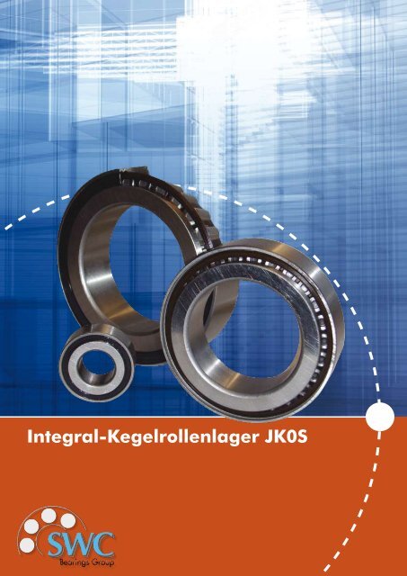
<strong>Integral</strong>-<strong>Kegelrollenlager</strong> <strong>JK0S</strong>
<strong>Integral</strong>-<strong>Kegelrollenlager</strong> Reihe <strong>JK0S</strong><br />
<strong>Integral</strong> Tapered Roller Bearings of Series <strong>JK0S</strong><br />
SWC <strong>Integral</strong>-<strong>Kegelrollenlager</strong> sind auf einer Seite abgedichtet;<br />
sie sind selbsthaltend und auf Lebensdauer<br />
mit Fett geschmiert. Man baut sie paarweise ein, so<br />
dass sich eine auf beiden Seiten abgedichtete Lagerung<br />
ergibt.<br />
Auf Grund der großen Stützbasis nimmt die Lagerung<br />
alle Belastungskombinationen auf aus Radialkräften,<br />
Axialkräften und Kippkräften.<br />
Bei Konstruktionen mit sehr hohen Belastungen und<br />
nicht allzu hohen Drehzahlen, z. B. Laufrollen, Kranlaufrädern,<br />
Seilrollen, ergeben sich mit <strong>Integral</strong>-<strong>Kegelrollenlager</strong>n<br />
besonders kostengünstige Lagerungen.<br />
Vorteile<br />
» Leichte Montage: einbaufertige Einheit<br />
(selbsthaltend) aus Innenring, Außenring,<br />
Rollensatz und Dichtung.<br />
» Kein Einstellen der Lagerluft: beim paarweisen<br />
Einbau in O-Anordnung automatisch<br />
richtige Luft.<br />
» Wartungsfreie Lagerung: Lebensdauerfet tung<br />
der Lager; doppellippige Dichtung mit geringer<br />
Reibung auf beiden Seiten des Lagerpaars.<br />
SWC integral tapered roller bearings are sealed at one<br />
side; they are self retaining and greased for life. They<br />
are mounted in pairs such that a bearing unit sealed at<br />
both ends is obtained.<br />
Due to the large spread the bearing unit accommodates<br />
all load combinations from radial loads, axial<br />
loads, and tilting moments.<br />
Particularly economical solutions are tained with integral<br />
tapered roller bearings for constructions subject<br />
to very high loading an moderate speeds, for instance,<br />
idlers, crane run wheels, sheaves.<br />
Advantages<br />
»<br />
»<br />
»<br />
Easy mounting: Ready-to-mount unit (selfretaining)<br />
consisting of cone, cup, roller<br />
set, and seal.<br />
Adjustment of the bearing clearance not<br />
necessary: The correct clearance is auto<br />
matically obtained by assembling the<br />
bearings in O-arranged pairs.<br />
Maintenance-free bearing assembly:<br />
Grease lubrication for life; double-lip, lowfriction<br />
seal at both sides of the bearing<br />
pair.
Lieferprogramm<br />
Die in dieser Druckschrift aufgeführten <strong>Integral</strong>-<strong>Kegelrollenlager</strong><br />
fertigt SWC in Serien.<br />
Auch kleine Bestellmengen werden ohne Preisaufschlag<br />
geliefert.<br />
Die im Druck hervorgehobenen Ausführungen gehören<br />
zum SWC Standardprogramm.<br />
Einbau<br />
Beim paarweisen Einbau der <strong>Integral</strong>-<strong>Kegelrollenlager</strong><br />
in O-Anordnung stellt sich die richtige Axialluft von<br />
selbst ein. Es genügt, wenn folgende Passungen eingehalten<br />
werden:<br />
» bei Umfanglast für Innenringe:<br />
Wellentoleranz m6; Gehäusetoleranz H7;<br />
» bei Umfanglast für Außenringe:<br />
Wellentoleranz g6; Gehäusetoleranz M7.<br />
Die Innenringe werden axial zusammengespannt, beispielsweise<br />
mit einer Wellenmutter oder einer Wellenendkappe.<br />
Die maximale Zusammenspannkraft für das<br />
Lagerpaar geht aus der Maßtabelle hervor.<br />
Die Außenringe legt man axial mit einem Sprengring im<br />
Gehäuse fest (Tragfähigkeit der Sprengring-Verbindung<br />
siehe Maßtabelle).<br />
Werden auf einer Welle mehrere Lagerpaare nebeneinander<br />
eingebaut, sind dennoch unterschiedliche<br />
Drehzahlen der Außenringe möglich, da die Innenringe<br />
bei <strong>Integral</strong>-<strong>Kegelrollenlager</strong>n breiter als die Außenringe<br />
sind. Dies ist besonders vorteilhaft bei Seilrollen.<br />
Delivery Programme<br />
The SWC integral tapered roller bearings listed in this<br />
publication are produced in series. Also small quantities<br />
are supplied without extra charge.<br />
The bold-faced designs are covered by the SWC Standard<br />
Programme.<br />
Mounting<br />
When mounting integral tapered roller bearings in O-<br />
arranged pairs the correct axial clearance is automatically<br />
obtained if the following fits are observed:<br />
»<br />
»<br />
Circumferential load on cone:<br />
Shaft tolerance field m6; Housing tolerance<br />
field H7<br />
Circumferential load on cup:<br />
Shaft tolerance field g6; Housing tolerance<br />
field M7<br />
The cones are axially clamped, for instance by a shaft<br />
nut or a shaft end cap. The maximum clamping force<br />
for the bearing pair is indicated in the dimensional table.<br />
The cups are axially located in the housing bore by<br />
a snap ring. (The load carrying of the snap ring joint<br />
is indicated in the dimensional table). Since the cones<br />
of integral tapered roller bearings are wider than the<br />
cups, the cups of several, bearing pairs mounted side<br />
by side on a shaft can rotate at different speeds. This is<br />
particularly advantageous for sheaves.
Dimensionierung<br />
Bei der Berechnung paarweise angeordneter <strong>Integral</strong>-<br />
<strong>Kegelrollenlager</strong> wird jedes einzelne Lager für sich betrachtet.<br />
Dementsprechend sind in der Maßtabelle die<br />
Tragzahlen (C, C0), der e-Wert und die Axialfaktoren<br />
(Y, Y0) für das Einzellager aufgeführt.<br />
Dynamisch äquivalente Belastung des einzelnen <strong>Kegelrollenlager</strong>s<br />
P = F r [kN] für — < e<br />
F r<br />
=<br />
P = 0,4 . F r + Y . F a [kN] für — > e<br />
F r<br />
F a<br />
F a<br />
Statisch äquivalente Belastung des einzelnen <strong>Kegelrollenlager</strong>s<br />
1<br />
P 0 = F r [kN] für — < ——<br />
F r<br />
= 2.Y 0<br />
P 0 = 0,5 . F r + Y 0<br />
.<br />
F<br />
F a [kN] für — a<br />
1<br />
> ——<br />
F r<br />
2.Y 0<br />
F a<br />
Wegen der Neigung der Laufbahnen erzeugt eine Radialbelastung<br />
bei <strong>Kegelrollenlager</strong>n axiale Reaktionskräfte,<br />
die bei der Ermittlung der äquivalenten Belastung<br />
berücksichtigt werden müssen.<br />
Die Axialkraft wird mit den Formeln der folgenden Tafel<br />
errechnet. Das Lager, das die äußere Axialkraft K,<br />
aufnimmt, wird als Lager „A“, das andere Lager als „B“<br />
bezeichnet.<br />
In den Belastungsfälle, für die keine Formeln angegeben<br />
sind, wird die Axialkraft F, nicht berücksichtigt.<br />
Lastverhältnisse<br />
Axialkraft Fa, die bei der Berechnung der dynamisch äquivalenten Belastung einzusetzen ist.<br />
Y=Y A =Y B Lager A Lager B<br />
F<br />
<<br />
rA = F rB F a = K a + 0,5 . -<br />
Y<br />
F rA > F rB<br />
F<br />
K a > 0,5 (<br />
rA - F rB<br />
F<br />
)<br />
rB<br />
. F a = K a + 0,5 . -<br />
Y<br />
Y<br />
( )<br />
F rA > F rB<br />
F rA - F rB<br />
F rA<br />
K a<br />
<<br />
= 0,5 . - F a = 0,5 . - K<br />
Y<br />
Y a<br />
F rB
Dimensioning<br />
The formulae of single integral tapered roller bearings<br />
are applied for their dimensioning also when they are<br />
mounted in pairs. Accordingly, the dimensional table<br />
indicates the load ratings (C, C0), the e value, and the<br />
thrust factors (Y, Y0) for the single bearings.<br />
Equivalent dynamic load of the single tapered roller<br />
bearing<br />
P = F r [kN] when — < e<br />
F r<br />
=<br />
P = 0,4 . F r + Y . F a [kN] when — > e<br />
F r<br />
F a<br />
F a<br />
Due to the inclination of the raceways of tapered roller<br />
bearings a radial load provokes an axial reaction<br />
Equivalent static load of the single tapered roller bearing<br />
which must be considered for the determination of the<br />
F a 1<br />
equivalent load.<br />
P 0 = F r [kN] when — < ——<br />
F r<br />
= 2.Y<br />
The axial load is calculated to the formulae of the list<br />
0<br />
below.<br />
P 0 = 0,5 . F r + Y 0<br />
.<br />
F<br />
F a [kN] when — a<br />
1<br />
> —<br />
The bearing accommodating the external axial load<br />
F r<br />
2.Y 0<br />
“K”, is identified by “A”, the other bearing by “B”.<br />
In the load cases not described by formulae the axial<br />
load “F”, is not considered.
Shaft<br />
Dimension<br />
Load rating . factor<br />
Welle Abmessung<br />
mm d D B C<br />
r 1s, r 2s<br />
min<br />
D n<br />
b n<br />
2<br />
a<br />
~<br />
u<br />
+0,05<br />
Tragzahl . Faktor<br />
dyn.<br />
C e<br />
kN<br />
Y<br />
sat.<br />
C o<br />
kN<br />
Y 0<br />
mm d D B C<br />
r 1s, r 2s<br />
min<br />
D n<br />
b n<br />
2<br />
a<br />
~<br />
u<br />
+0,05<br />
dyn.<br />
C<br />
kN<br />
e<br />
Y<br />
sat.<br />
C o<br />
kN<br />
Y 0<br />
20 20 42 17 16,5 0,6 38,1 0,75 11,1 0,025 22,8 0,37 1,6 29 0,9<br />
25 25 47 17 16,5 0,6 43,1 0,75 12,4 0,015 25 0,42 1,4 34 0,8<br />
30 30 55 19 18,5 1 51,4 0,75 14,8 0,02 36 0,43 1,4 46,5 0,8<br />
35 35 62 20 19,5 1 58,4 0,75 16,2 0,02 36 0,44 1,4 50 0,7<br />
40 40 68 21 20,5 1 64,4 0,75 15,8 0,03 50 0,37 1,6 69,5 0,9<br />
45 45 75 22 21,5 1 70,7 1 17,2 0,02 55 0,38 1,6 81,5 0,9<br />
50 50 80 22 21,5 1 75,7 1 18,7 0,02 60 0,42 1,4 93 0,8<br />
60 60 95 26 25 1,5 89,8 1,25 23,1 0,03 76,5 0,43 1,4 122 0,8<br />
70 70 110 27 26,5 1,5 104,8 1,25 25 0,03 98 0,43 1,4 160 0,8<br />
80 80 125 30 29,5 1,5 119,8 1,25 28 0,03 129 0,42 1,4 212 0,8<br />
90 90 140 33,5 33 2 133,7 1,25 31,6 0,03 156 0,42 1,4 260 0,8<br />
100 100 150 33,5 33 2 143,6 1,25 34,4 0,03 166 0,46 1,3 290 0,7
Technical Data<br />
Technische Daten<br />
Maximum<br />
Axial clamping<br />
force bearing<br />
pair<br />
kN<br />
Load carrying capacity<br />
of the snap<br />
ring joint 3)<br />
F BR<br />
Limiting<br />
Speed 1)<br />
Grease<br />
min -1<br />
Abutments<br />
Shaft D 2<br />
min<br />
mm<br />
Nut<br />
D 5<br />
Nominal<br />
dimension<br />
Tolerance<br />
Number<br />
Bearing<br />
Snapring<br />
Weight<br />
~<br />
kg<br />
Maximale<br />
Zusammenspannkraft<br />
Lagerpaar<br />
kN<br />
Tragfähigkeit der<br />
Sprengringverbindung<br />
3)<br />
F BR<br />
Drehzahlgrenze<br />
1)<br />
Fett<br />
min -1<br />
Einbaumaß<br />
Welle D 2<br />
min<br />
mm<br />
Nut<br />
D 5<br />
Nennmaß<br />
Abmaß<br />
Kurzzeichen<br />
Lager<br />
Sprengring<br />
Gewicht<br />
~<br />
kg<br />
4,5 13,3 4800 25 43,2 +0,16 <strong>JK0S</strong> 020 BR42 0,1<br />
5 14,9 4000 30 48,2 +0,16 <strong>JK0S</strong> 025 BR47 0,128<br />
7,2 15,7 3400 36 56,5 +0,19 <strong>JK0S</strong> 030 BR55 0,18<br />
7,2 14,2 3000 41 63,5 +0,19 <strong>JK0S</strong> 035 BR62 0,24<br />
10 12,9 2700 46 69,5 +0,19 <strong>JK0S</strong> 040 BR68 0,29<br />
11 33,8 2400 51 76,8 +0,19 <strong>JK0S</strong> 045 BR76 0,363<br />
12 31,4 2200 56 81,8 +0,22 <strong>JK0S</strong> 050 BR80 0,403<br />
15,3 50,2 1800 67 97 +0,22 <strong>JK0S</strong> 060 BR95 0,62<br />
19,6 49 1500 77 112,3 +0,22 <strong>JK0S</strong> 070 BR110 0,9<br />
25,8 40,2 1300 87 127,3 +0,25 <strong>JK0S</strong> 080 BR125 1,33<br />
31,2 40,2 1200 99 142,6 +0,25 <strong>JK0S</strong> 090 BR140 1,9<br />
33,2 36,2 1100 109 152,6 +0,25 <strong>JK0S</strong> 0100 BR150 2
SWC Wälzlagerfabrikation SW GmbH<br />
Am Lagerhaus 2 / OT Oberwerrn<br />
D-97464 Niederwerrn (Germany)<br />
Fon: +49 9726 / 91 32 - 0<br />
Fax: +49 9726 / 91 32 - 30<br />
Mail: info@swc-bearings.de<br />
www: www.swc-bearings.de<br />
Alle Angaben wurden sorgfältig erstellt und<br />
überprüft. Für eventuelle Fehler oder Unvollständigkeiten<br />
können wir jedoch keine Haftung<br />
übernehmen. Änderungen die dem Fortschritt<br />
dienen, behalten wir uns vor.<br />
© SWC<br />
Nachdruck, auch auszugsweise, nur mit unserer<br />
Genehmigung.