
You also want an ePaper? Increase the reach of your titles
YUMPU automatically turns print PDFs into web optimized ePapers that Google loves.
PRODUCT DATA SHEET<br />
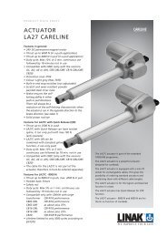
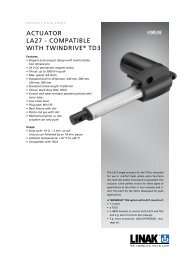
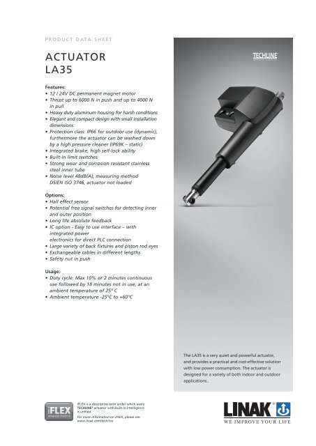
ACTUATOR<br />
LA35<br />
Features:<br />
• 12 / 24V DC permanent magnet motor<br />
• Thrust up to 6000 N in push and up to 4000 N<br />
in pull<br />
• Heavy duty aluminum housing for harsh conditions<br />
• Elegant and compact design with small installation<br />
dimensions<br />
• Protection class: IP66 for outdoor use (dynamic),<br />
furthermore the <strong>actuator</strong> can be washed down<br />
by a high pressure cleaner (IP69K – static)<br />
• Integrated brake, high self-lock ability<br />
• Built-in limit switches<br />
• Strong wear and corrosion resistant stainless<br />
steel inner tube<br />
• Noise level 48dB(A); measuring method<br />
DS/EN ISO 3746, <strong>actuator</strong> not loaded<br />
Options:<br />
• Hall effect sensor<br />
• Potential free signal switches for detecting inner<br />
and outer position<br />
• Long life absolute feedback<br />
• IC option - Easy to use interface – with<br />
integrated power<br />
electronics for direct PLC connection<br />
• Large variety of back fixtures and piston rod eyes<br />
• Exchangeable cables in different lengths<br />
• Safety nut in push<br />
Usage:<br />
• Duty cycle: Max 10% or 2 minutes continuous<br />
use followed by 18 minutes not in use, at an<br />
ambient temperature of 25º C<br />
• Ambient temperature -25°C to +60°C<br />
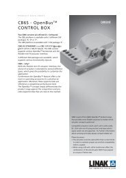
The LA35 is a very quiet and powerful <strong>actuator</strong>,<br />
and provides a practical and cost-effective solution<br />
with low power consumption. The <strong>actuator</strong> is<br />
designed for a variety of both indoor and outdoor<br />
applications..<br />
iFLEX is a descriptive term under which every<br />
TECHLINE ® <strong>actuator</strong> with built-in intelligence<br />
is unified.<br />
For more information on iFLEX, please see:<br />
www.linak.com/techline
Technical specifications:<br />
LA35 with 12V motor<br />
Order number<br />
Push<br />
Max.<br />
(N)<br />
Pull<br />
Max.<br />
(N)<br />
Selflock<br />
min.<br />
(N)<br />
Push<br />
Selflock<br />
min.<br />
(N)<br />
Pull<br />
pitch<br />
(mm/<br />
spindle<br />
rev.)<br />
Typical<br />
speed<br />
(mm/s)<br />
Standard<br />
stroke<br />
lengths<br />
(mm)<br />
in steps of<br />
50mm<br />
Typical amp.<br />
3510xx. 6000 4000 6000 4000 3 4.7 3.3 100-300 1.6 7.5<br />
No<br />
load<br />
Full<br />
load<br />
No<br />
load<br />
Full<br />
load<br />
3520xx. 4000 4000 1500 1500 5 7.7 5.3 100-400 1.7 7.7<br />
3521xx. push brake 4000 4000 2500 1500 5 7.2 5.4 100-400 3.2 7.8<br />
3522xx. pull brake 4000 4000 1500 2500 5 6.9 5.9 100-400 4.2 8.4<br />
3530xx. 1500 1500 750 750 9 14.0 12.3 100-500 1.7 5.9<br />
3531xx. push brake 1500 1500 1000 750 9 14.2 12.6 100-500 2.9 5.5<br />
3532xx. pull brake 1500 1500 750 1000 9 14.4 11.2 100-500 3.0 5.4<br />
3540xx. 1000 1000 750 750 12 19.0 17.0 100-600 1.9 5.3<br />
3541xx. push brake 1000 1000 1000 750 12 17.9 16.9 100-600 5.5 5.5<br />
3542xx. pull brake 1000 1000 750 900 12 16.9 15.4 100-600 5.6 5.6<br />
LA35 with 24V motor<br />
Order number<br />
Push<br />
Max.<br />
(N)<br />
Pull<br />
Max.<br />
(N)<br />
Selflock<br />
min.<br />
(N)<br />
Push<br />
Selflock<br />
min.<br />
(N)<br />
Pull<br />
pitch<br />
(mm/<br />
spindle<br />
rev.)<br />
No<br />
load<br />
Typical<br />
speed<br />
(mm/s)<br />
Full<br />
load<br />
Standard<br />
stroke<br />
lengths<br />
(mm)<br />
in steps of<br />
50mm<br />
Typical amp.<br />
3510xx. 6000 4000 6000 4000 3 5.1 4.0 100-300 0.9 4.2<br />
No<br />
load<br />
Full<br />
load<br />
3520xx. 4000 4000 1500 1500 5 8.3 6.6 100-400 0.8 4.8<br />
3521xx. push brake 4000 4000 2500 1500 5 8.0 6.7 100-400 1.4 4.3<br />
3522xx. pull brake 4000 4000 1500 2500 5 8.0 7.0 100-400 2.1 4.6<br />
3530xx. 1500 1500 750 750 9 15.0 13.9 100-500 0.6 2.6<br />
3531xx. push brake 1500 1500 1000 750 9 14.5 14.1 100-500 1.2 2.9<br />
3532xx. pull brake 1500 1500 750 1000 9 14.7 13.9 100-500 1.5 3.0<br />
3540xx. 1000 1000 750 750 12 19.5 18.9 100-600 0.9 2.8<br />
3541xx. push brake 1000 1000 1000 750 12 18.9 17.8 100-600 1.3 2.8<br />
3542xx. pull brake 1000 1000 750 900 12 18.7 18 100-600 1.5 2.9
Stroke length vs. load:<br />
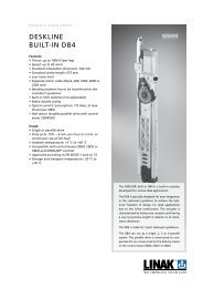
Dimensions:<br />
10.2<br />
10.2<br />
Installation dimension<br />
Stroke =300 = 250 + Stroke<br />
Minimum installation dimension = 300 mm<br />
116<br />
29<br />
22<br />
54<br />
26<br />
6.1<br />
153<br />
11 17 17 13<br />
6.1<br />
27<br />
233<br />
27<br />
83.5<br />
Drawing no.: 0359012<br />
Back fixtures:<br />
Type 1, 3, A<br />
Type 2, 4, B
LA35<br />
Ordering example:<br />
35 1 0 A 0 + 0 0 2 0 0 0 2 1<br />
CABLE:<br />
IP-DEGREE:<br />
MOTOR TYPE:<br />
0 = No cable<br />
1 = 1,5 m power cable (0367046-1500)<br />
2 = 5 m power cable (0367046-5000)<br />
3 = 0,2 m power cable with AMP connector (0367006)<br />
4 = 1,5 m power and 1,5 signal (0367046-1500/0367049-1500)<br />
5 = 5 m power and 5 m signal (0367046-5000+0367049-5000)<br />
6 = 1,5 m Y-cable power and signal in one (0367020)<br />
7 = 5 m powercable & datacable M 12x1 (Bus) **<br />
2 = IP66 Dynamic / IP69K Static<br />
A = 12VDC<br />
B = 24VDC<br />
STROKE LENGTH: XXX = mm Acme spindle: 50, 150....600 mm<br />
FEEDBACK:<br />
PCB OPTIONS:<br />
0 = Standard (No feedback)<br />
H = Hall signal<br />
A = Analog feedback 0-10V<br />
B = Analog feedback 0,5-4,5V<br />
D = Bus **<br />
0 = None<br />
1 = Potential free endstop signals<br />
* iFLEX options for LA35:<br />
2 = IC option - please see page 12 for further information<br />
A = Modbus **<br />
SAFETY OPTIONS: '+ = None<br />
1 = Safety Nut<br />
2 = Splines<br />
3 = Splines with safety nut.<br />
PISTON ROD EYE: 0 = Ø10,2 hole (for 10mm pin) with slot<br />
1 = Ø10H8 hole with slot (for 10mm pin) - AISI 303<br />
2 = Ø12,9 hole with slot (for 1/2" pin)<br />
3 = Ball eye Ø10H7<br />
4 = Ball eye Ø12H7<br />
BACK FIXTURE: A = Ø10.2 hole (for 10mm pin) - AISI 304<br />
B = Ø10,2 hole turned 90 degrees - AISI 304<br />
C = Ø12,9 (for 1/2" pin) - AISI 304<br />
D = Ø12,9 turned 90 degrees - AISI 304<br />
E = Ball eye Ø10H7<br />
F = Ball eye Ø10H7 turned 90 degrees<br />
G = Ball eye Ø12H7<br />
H = Ball eye Ø12H7 turned 90 degrees<br />
BRAKE:<br />
SPINDLE TYPE:<br />
0 = None<br />
1 = Brake Push<br />
2 = Brake pull<br />
1 = 3 mm<br />
2 = 5 mm<br />
3 = 9 mm<br />
4 = 12 mm<br />
7 = 6 mm<br />
*<br />
ACTUATOR TYPE: 35 = LA35<br />
iFLEX options: IC Modbus<br />
LA14 <strong>actuator</strong>: <br />
** Cables option 7, Feedback option D and PCB option A are connected and can only be configured with Motor Type B
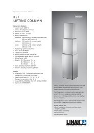
Connection diagrams:<br />
Basic <strong>actuator</strong><br />
Fig.1 : 35xxxxx00xxxxx<br />
BROWN<br />
M<br />
BLUE<br />
Actuator with potential free switches<br />
Fig.2 : 35xxxxx10xxxxx<br />
M<br />
BROWN<br />
BLUE<br />
RED<br />
IN<br />
OUT<br />
YELLOW<br />
GREEN<br />
Actuator with potential free switches and relative positioning<br />
Fig.3 : 35xxxxx0Hxxxxx & 35xxxxx1Hxxxxx<br />
M<br />
BROWN<br />
BLUE<br />
IN<br />
OUT<br />
SIGNAL<br />
RED<br />
YELLOW<br />
GREEN<br />
WHITE<br />
VIOLET<br />
BLACK
Actuator with potential free switches and absolute positioning<br />
Fig.4 : 35xxxxx0Axxxxx & 35xxxxx1Axxxxx<br />
M<br />
BROWN<br />
BLUE<br />
IN<br />
OUT<br />
SIGNAL<br />
RED<br />
YELLOW<br />
GREEN<br />
WHITE<br />
VIOLET<br />
BLACK<br />
Actuator with IC-option<br />
Fig.5 : 35xxxxx20xxxxx & 35xxxxx2Hxxxxx & 35xxxxx2Axxxxx<br />
M<br />
BROWN<br />
BLUE<br />
12/24V DC<br />
BLACK<br />
RED<br />
YELLOW<br />
GREEN<br />
WHITE<br />
VIOLET<br />
PLC OUTPUT<br />
INWARDS<br />
OUTWARDS<br />
ENDSTOP IN<br />
ENDSTOP OUT<br />
READY<br />
DIGITAL/ANALOG<br />
INPUT
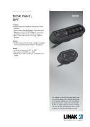
Speed and current curves:<br />
Ampere<br />
LA35 LA35 12V 12V motor Motor current current v´s vs. load load<br />
9<br />
8<br />
3520xx.<br />
3510xx.<br />
7<br />
6<br />
3530xx.<br />
3540xx.<br />
5<br />
4<br />
3<br />
2<br />
1<br />
0<br />
0 1000 2000 3000 4000 5000 6000 7000<br />
Load (N)<br />
Speed (mm/s)<br />
20<br />
18<br />
16<br />
14<br />
12<br />
10<br />
8<br />
6<br />
4<br />
2<br />
LA35 12V LA35 motor 12V Motor speed speed v´s vs. load load<br />
3540xx.<br />
3530xx.<br />
0<br />
0 1000 2000 3000 4000 5000 6000 7000<br />
Load (N)<br />
3520xx.<br />
3510xx.<br />
6<br />
LA35 LA35 24V 24V motor Motor current current v´s vs. load load<br />
5<br />
3520xx.<br />
Ampere<br />
4<br />
3<br />
2<br />
3540xx.<br />
3530xx.<br />
3510xx.<br />
1<br />
0<br />
0 1000 2000 3000 4000 5000 6000 7000<br />
Load (N)<br />
25<br />
LA35 24V LA35 motor 24V Motor speed speed v´s vs. load load<br />
20<br />
3540xx.<br />
Speed (mm/s)<br />
15<br />
10<br />
5<br />
3530xx.<br />
3520xx.<br />
3510xx.<br />
0<br />
0 1000 2000 3000 4000 5000 6000 7000<br />
Load (N)
The LA35 is tested according to the following standards:<br />
Test Specification Comment<br />
Cold test<br />
Dry heat<br />
Change of temperature<br />
Damp heat<br />
EN60068-2-1 (Ab)<br />
EN60068-2-1 (Ad)<br />
EN60068-2-2 (Bb)<br />
EN60068-2-2 (Bd)<br />
EN60068-2-14 (Na)<br />
EN60068-2-14 (Nb)<br />
EN60068-2-30 (Db)<br />
EN60068-2-3 (Ca)<br />
Storage at low temperature: -40°C<br />
Operating at low temperature: -30°C<br />
Storage at high temperature: +90°C<br />
Operating at high temperature: +60°C<br />
Rapid change in temperature: +100°C to -30°C<br />
Controlled change of temperature: +70°C to -30°C<br />
Damp heat, Cyclic: Relative humidity 93 - 98 %, High +55°C, low +25°C<br />
Damp heat, Steady: Relative humidity 93 - 95 %, +40°C ± 2°C<br />
Salt spray EN60068-2-52 (Kb) Salt spray test: 500 hours incl. spraying periods + humidity storage<br />
Degrees of protection<br />
EN60529-IP66<br />
DIN40050 -IP69K DUNK<br />
test<br />
IP6X – Dust: Dust-tight<br />
IPX6 – Water: No ingress of water causing damage<br />
Warmed up to 115°C for 20 hours, cooled down in 20°C saltwater<br />
Chemicals BS7691/96 hours Resistant against: diesel, hydraulic oil, ethylene glycol, urea nitrogen, liquid<br />
lime, NPK fertilizers<br />
Free fall<br />
Vibration<br />
EN60068-2-36 (Fdb)<br />
EN60068-2-6 (Fc)<br />
Free fall from all sides: 0.4 meters on to steel<br />
Random vibration: Short time 6.29 g RMS (Rod Mean Square)<br />
Long time 7.21 g RMS<br />
Sinus vibration: Freq. 5 - 25 Hz, amplitude = 3.3 mm pp<br />
Freq. 25 - 200 Hz, acceleration 4 g<br />
Bump EN60068-2-29 (Eb) Bump test: Level 40 g for 6 milliseconds. 3,000 bumps<br />
Shock EN60068-2-27 (Ea) Shock test: Level 100 g for 6 milliseconds<br />
Electromagnetic fields<br />
ISO 11452-2 1m distance<br />
EN 61000-4-3<br />
30 V/m, 80%AM, 1 kHz 20 - 2.700 Mhz<br />
10 V/m, 80% AM, 1kHz 80 - 1000 Mh<br />
3 V/m, 80% AM, 1 kHz 1.4 - 2.0 GHz<br />
1 V/m, 80% AM 2.0 - 2.7 GHz<br />
Radio frequency common mode IEC 61000-4-6 10 Vrms, 80% AM 0.15 - 80 MHz<br />
Conducted transients ISO 7637-2:2004 Pulses 1, 2, 3a, 3b, 4, 5<br />
ESD<br />
ISO 10605 IEC<br />
61000-4-2<br />
Burst transients IEC 61000-4-4 ± 2 kV<br />
8 kV contact discharge<br />
15 kV air discharge<br />
330 pF + 2.000 Ω<br />
Surge transients IEC 61000-4-5 ± 2 kV (42Ω output)<br />
Narrow Band 1m distance ISO 13766 52 - 42 dBμ V/m,<br />
30 - 75 MHz<br />
± 6 kV contact discharge ± 8 kV air discharge<br />
42 - 53 dBμ V/m,<br />
75 - 400 MHz<br />
53 dBμ V/m,<br />
400 - 1000 MHz<br />
Broad Band 1m distance ISO 13766 62 - 52 dBμ V/m,<br />
30 - 75 MHz<br />
Radiated emission 10 m<br />
distance<br />
CISPR 22<br />
52 - 63 dBμ V/m,<br />
75 - 400 MHz<br />
63 dBμ V/m,<br />
400 - 1000 MHz<br />
30 dBμ V/m,<br />
30 - 230 MHz<br />
37 dBμ V/m,<br />
230 - 1000 MHz<br />
Conducted emission DC port CISPR 22 79 dBμ V (QP),<br />
0.15 - 0.5 MHz<br />
66 dBμ V (AV),<br />
0.15 - 0.5 MHz<br />
73 dBμ V (QP),<br />
0.5 - 30 MHz<br />
60 dBμ V (AV),<br />
0.5 - 30 MHz<br />
Copyright © LINAK 2014 09 . MA M9-02-306-E . Chapter 5.13<br />
Terms of use<br />
The user is responsible for determining the suitability of LINAK products for specific application.<br />
LINAK takes great care in providing accurate and up-to-date information on its products.<br />
However, due to continuous development in order to improve its products, LINAK products are<br />
subject to frequent modifications and changes without prior notice. Therefore, LINAK cannot<br />
guarantee the correct and actual status of said information on its products.<br />
While LINAK uses its best efforts to fulfil orders, LINAK cannot, for the same reasons as<br />
mentioned above, guarantee the availability of any particular product. Therefore, LINAK reserves<br />
the right to discontinue the sale of any product displayed on its website or listed in its catalogues<br />
or other written material drawn up by LINAK.<br />
All sales are subject to the Standard Terms of Sale and Delivery for LINAK. For a copy hereof,<br />
please contact LINAK.<br />
FOR MOUNTING INSTRUCTIONS AND GUIDANCE IN USAGE, PLEASE SEE THE RELEVANT USER’S MANUALS