Split Type Room Air Conditioner Installation Manual - Friedrich Air ...
Split Type Room Air Conditioner Installation Manual - Friedrich Air ...
Split Type Room Air Conditioner Installation Manual - Friedrich Air ...

You also want an ePaper? Increase the reach of your titles
YUMPU automatically turns print PDFs into web optimized ePapers that Google loves.
OUTDOOR UNIT<br />
OUTDOOR UNIT INSTALLATION<br />
ELECTRICAL WIRING (OUTDOOR UNIT)<br />
●<br />
●<br />
Set the unit on a strong stand, such as one made of concrete blocks<br />
to minimize shock and vibration.<br />
Do not set the unit directly on the ground because it will cause trouble.<br />
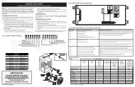
Connector cover removal<br />
●<br />
Remove the two mounting screws.<br />
Fig. 9<br />
1. Remove the screws, then remove the control box cover.<br />
2. Fasten the Inter unit wire harness and power supply to the conduit holder using the lock nut.<br />
3. Connect inter-unit wire harness and power supply to the terminal.<br />
Refer to the wiring diagram<br />
4. Use the screws to install the control box cover.<br />
Installing the connector cover<br />
(1) After inserting the three front hooks, then insert the rear hook.<br />
(2) Tighten the two mounting screws.<br />
WARNING<br />
(1) Install the unit where it will not be tilted by more<br />
than 5°.<br />
(2) When installing the outdoor unit where it may exposed<br />
to strong wind, fasten it securely.<br />
Tapping screw<br />
Front hooks<br />
Rear hooks<br />
Connector cover<br />
WARNING<br />
Be sure to comply with local codes while running<br />
the wire from the indoor unit to the outdoor<br />
unit (size of wire and wiring method, etc. ).<br />
Every wire must be connected firmly.<br />
No wire should be allowed to touch refrigerant<br />
tubing, the compressor or any moving part.<br />
NOTE:<br />
• Connector trade size for this unit is 1/2” (12.7 mm). The connector<br />
can be bought at a hardware store. Refer to “How to connect<br />
wiring to the terminals” for instructions on connecting depending<br />
on the wire type you are using.<br />
• The fuse located in the outdoor unit provides power supply protection<br />
and may blow when power is applied if the system has<br />
been incorrectly wired.<br />
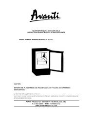
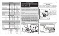
AIR PURGE<br />
Always use a vacuum pump to purge the air.<br />
Refrigerant for purging the air is not charged in the<br />
outdoor unit at the factory.<br />
Close the high pressure side valve of the gauge manifold fully and do<br />
not operate it during the following work.<br />
Loose wiring may cause the terminal to overheat<br />
or result in unit malfunction. A fire hazard<br />
may also exist. Therefore, be sure all wiring is<br />
tightly connected.<br />
Connect wires to the matching numbers of<br />
terminals.<br />
Lock nut<br />
1. Check if the piping connections are secure.<br />
2. Check that the stems of 2-way valve and 3-way valve are closed<br />
fully.<br />
3. Connect the gauge manifold charge hose to the charging port<br />
of the 3-way valve (side with the projection for pushing in the<br />
valve core).<br />
4. Open the low pressure side valve of the gauge manifold fully.<br />
5. Operate the vacuum pump and start pump down.<br />
6. Slowly loosen the flare nut of the 3-way valve and check if air<br />
enters, then retighten the flare nut.<br />
(When the flare nut is loosened the operating sound of the<br />
vacuum pump changes and the reading of the compound<br />
pressure gauge goes from minus to zero.)<br />
11. Firmly tighten the 2-way valve and 3-way valve blank cap and<br />
the charging port cap.<br />
Fig. 10<br />
3-way valve<br />
Charging port cap<br />
2-way valve<br />
Gauge manifold<br />
Compound pressure gauge<br />
Flare nut<br />
Valve stem<br />
Charging port<br />
-0.1 MPa<br />
(-76 cmHg<br />
-1 bar)<br />
Low pressure<br />
side valve<br />
Blank cap<br />
Charge hose<br />
LO HI<br />
Pressure gauge<br />
High<br />
pressure<br />
side valve<br />
(closed)<br />
Charge<br />
hose<br />
Vacuum pump<br />
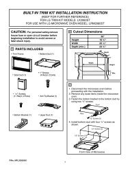
Fig. 11<br />
Indoor unit<br />
Terminal<br />
G<br />
3<br />
2<br />
1<br />
DISCONNECT<br />
SWITCH<br />
(FIELD SUPPLY)<br />
Grounding line<br />
Control line<br />
(Inter Unit)<br />
Power line<br />
208/230V<br />
208/230V<br />
208/230V<br />
Outdoor unit<br />
(L) (N)<br />
Terminal<br />
G<br />
5<br />
4<br />
1 2 3<br />
POWER SUPPLY<br />
1 phase, 208/230V<br />
Cord Clamp<br />
Conduit<br />
connector<br />
Power supply<br />
Inter-unit<br />
wire harness<br />
7. Pump down the system for at least 15 minutes, then check if the<br />
compound pressure gauge reads -0.1 MPa (-76 cmHg, -1 bar).<br />
8. At the end of pump down, close the low pressure side gauge of<br />
the gauge manifold fully and stop the vacuum pump.<br />
9. Slowly loosen the valve stem of the 3-way valve. When the<br />
compound pressure gauge reading reaches 0.1-0.2 MPa,<br />
retighten the valve stem and disconnect the charge hose<br />
from the 3-way valve charging port.<br />
(If the stem of the 3-way valve is opened fully before the<br />
charge hose is disconnected, it may be difficult to disconnect<br />
the charge hose.)<br />
Table 6<br />
Blank cap (2-way valve)<br />
Blank cap (3-way valve)<br />
Charging port cap<br />
Tightening torque<br />
14.47 to 18.08 ft•lbs (200 to 250 kgf•cm)<br />
20.25 to 23.15 ft•lbs (280 to 320 kgf•cm)<br />
9.04 to 11.57 ft•lbs (125 to 160 kgf•cm)<br />
CAUTION<br />
(1) Refrigerant must not be discharged into atmosphere.<br />
Earth screw<br />
G<br />
Indoor unit<br />
terminal block<br />
1 2 3 4<br />
Disconnect switch<br />
Outdoor unit<br />
terminal block<br />
1 2 3 4 5<br />
Earth screw<br />
G<br />
10. Fully open the valve stems of the 2-way valve and 3-way valve<br />
using a hexagon wrench. (After the valve stem begins to turn,<br />
turn it with a torque of less than 2.17ft •lbs (30 kgf•cm) until it<br />
stops turning.)<br />
(2) After connecting the piping , check the joints for<br />
gas leakage with gas leak detector.<br />
Power supply line