Split Type Room Air Conditioner Installation Manual - Friedrich Air ...
Split Type Room Air Conditioner Installation Manual - Friedrich Air ...
Split Type Room Air Conditioner Installation Manual - Friedrich Air ...

Create successful ePaper yourself
Turn your PDF publications into a flip-book with our unique Google optimized e-Paper software.
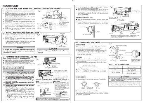
INDOOR UNIT<br />
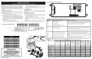
1. CUTTING THE HOLE IN THE WALL FOR THE CONNECTING PIPING<br />
(1) Cut a 3-2/16’’(80 mm) diameter hole in the wall at the position shown<br />
in (Fig.1).<br />
(2) When cutting the wall hole at the inside of the wall hook bracket,<br />
cut the hole within the range of the left and right center marks<br />
3/8’’(10 mm) below the installation frame.<br />
When cutting the wall hole at the outside of the wall hook bracket,<br />
cut the hole at least 3/8’’(10 mm) below less.<br />
(3) Cut the hole so that the outside end is lower 3/16’’ to 3/8’’ (5 to 10 mm)<br />
than the inside end.<br />
(4) Always align the center of the wall hole. If misaligned, water leakage<br />
will occur.<br />
(5) Cut the wall pipe to match the wall thickness, stick it into the wall<br />
cap, fasten the cap with vinyl tape, and stick the pipe through the<br />
hole. (The connection pipe is supplied in the installation set.)<br />
(Fig.1)<br />
(6) For left piping and right piping, cut the hole a little lower so that<br />
drain water will flow freely. (Fig.1)<br />
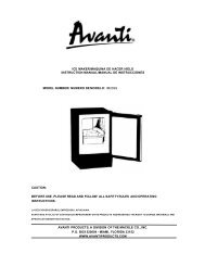
2. INSTALLING THE WALL HOOK BRACKET<br />
(1) Install the wall hook bracket so that it is correctly positioned horizontally<br />
and vertically. If the wall hook bracket is titled, water will<br />
drip to the floor.<br />
(2) Install the wall hook bracket so that it is strong enough to withstand<br />
the weight of an adult.<br />
●<br />
●<br />
Fasten the wall hook bracket to the wall with 6 or more screws<br />
through the holes near the outer edge of the bracket.<br />
Check that there is no rattle at the wall hook bracket.<br />
WARNING<br />
If the wall pipe is not used, the cord interconnecting<br />
the indoor and outdoor units may touch metal and<br />
cause electric leakage.<br />
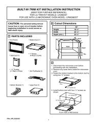
3. FORMING THE DRAIN HOSE AND PIPE<br />
[Rear piping, Right piping, Bottom piping]<br />
●<br />
●<br />
●<br />
Install the indoor unit piping in the direction of the wall hole and<br />
bind the drain hose and pipe together with vinyl tape. (Fig. 3)<br />
Install the piping so that the drain hose is at the bottom.<br />
Wrap the pipes of the indoor unit that are visible from the outside<br />
with decorative tape.<br />
[For Left rear piping, Left piping]<br />
Interchange the drain cap and the drain hose.<br />
CAUTION<br />
(1) In order to align the drain hose and drain cap, be<br />
sure to insert securely and vertically. Incline insertion<br />
will cause water leakage.<br />
(2) When inserting, be sure not to attach any material<br />
besides water. If any other material is attached,<br />
it will cause deterioration and water leakage.<br />
(3) After removing drain hose, be sure not to forget<br />
mounting drain cap.<br />
(4) Be sure to fix the drain hose with tape to the bottom<br />
of piping.<br />
(5) Prevent drain water frozen under low temperature<br />
environment.<br />
When installing indoor unit's drain hose outdoors,<br />
necessary measure for frost protection should be<br />
taken to prevent drain water frozen.<br />
● Under low temperature environment (when outdoor<br />
temperature under 32 °F), after cooling operation<br />
is executed, water in the drain hose could<br />
be frozen.<br />
Once drain water is frozen, the drain hose will<br />
be blocked and water leakage may be resulted<br />
for indoor unit.<br />
Fig. 1<br />
Fasten with<br />
vinyl tape<br />
(Wall cap)<br />
Fig. 2<br />
Wall hook bracket<br />
Tapping screw<br />
Wall hook<br />
String<br />
bracket<br />
Counter weight<br />
CAUTION<br />
Center notch<br />
Hook<br />
Install the wall hook bracket horizontally and perpendicularly.<br />
Fig. 3<br />
Right piping<br />
Lower<br />
3/8’’(10 mm)<br />
or over<br />
(Wall pipe)<br />
(Inside)<br />
Bottom<br />
piping<br />
Indoor unit<br />
drain hose<br />
3-2/16’’(80 mm)<br />
dia. hole<br />
Wall<br />
Drain cap<br />
Removal method of drain<br />
hose<br />
●<br />
Remove the screw at the left of<br />
drain hose and pull out drain<br />
hose.<br />
Screw<br />
Drain fixture<br />
(blue)<br />
Drain hose<br />
Center mark<br />
3/16’’ to 3/8’’<br />
(5 to 10 mm)<br />
low<br />
(Outside)<br />
Bind with vinyl tape<br />
Pipe (top)<br />
Rear piping<br />
Indoor unit drain hose<br />
(bottom)<br />
Lower<br />
3/8’’(10 mm)<br />
or over<br />
3-2/16’’(80 mm) dia. hole<br />
(A 2-9/16’’(65mm)<br />
diameter hole is<br />
possible for the righthand<br />
side.)<br />
For left outlet piping, cut off the<br />
piping outlet cutting groove<br />
with a hacksaw.<br />
Remove the drain cap by pulling<br />
at the projection at the end of<br />
the cap with pliers, etc.<br />
<strong>Installation</strong> method of<br />
drain hose<br />
●<br />
Vertically insert the drain hose<br />
toward the inside, so that the<br />
drain fixture (blue) can accurately<br />
align with the screw hole<br />
around the drain cock.<br />
After inserting and before replacing,<br />
please reinstall and fix<br />
the removed screws.<br />
Drain fixture (blue)<br />
Screw hole<br />
Drain cock<br />
Screw<br />
Drain hose<br />
● Be sure to install around the drain hose connector.<br />
● As the screw is inside, be sure to use screwdriver treated with magnet.<br />
●<br />
●<br />
●<br />
For left piping and left rear piping, align the marks on the wall<br />
hook bracket and shape the connection pipe.<br />
Bend the connection piping at a bend radius of 2- 3/4’’(70 mm) or<br />
more and install no more than 1- 3/8’’(35 mm) from the wall.<br />
After passing the indoor piping and drain hose through the wall<br />
hole, hang the indoor unit on the hooks at the top and bottom of<br />
the wall hook bracket.<br />
[Installing the indoor unit]<br />
●<br />
●<br />
Hang the indoor unit from the hooks at the top of the wall hook<br />
bracket.<br />
Insert the spacer, etc. between the indoor unit and the wall hook<br />
bracket and separate the bottom of the indoor unit from the wall.<br />
Indoor unit<br />
Wall hook bracket<br />
(Spacer)<br />
4. CONNECTING THE PIPING<br />
CONNECTION<br />
(1) Install the outdoor unit wall cap (supplied with the optional installation<br />
set or procured at the site) to the wall pipe.<br />
(2) Connect the outdoor unit and indoor unit piping.<br />
(3) After matching the center of the flare surface and tightening the<br />
nut hand tight, tighten the nut to the specified tightening torque<br />
with a torque wrench. (Tighten the flare nut of the outdoor unit<br />
3-way valve after air purging.)<br />
FLARING<br />
(1) Cut the connection pipe to the necessary length with a pipe cutter.<br />
(2) Hold the pipe downward so that cuttings will not enter the pipe<br />
and remove the burrs.<br />
(3) Insert the flare nut onto the pipe and flare the pipe with a flaring<br />
tool.<br />
BENDING PIPES<br />
Check if [L] is flared uniformly<br />
and is not cracked or scratched.<br />
L dimension<br />
Thin pipe 1/4” (6.35 mm)dia. ...... 1/16” (1.4 to 1.7 mm)<br />
Thick pipe 1/2” (12.7 mm)dia. ...... 5/64” (1.9 to 2.2 mm)<br />
The pipes are shaped by your hands. Be careful not to collapse them.<br />
OK<br />
Extend the pipe<br />
by unwinding it.<br />
NO<br />
Do not bend the pipes in an angle more than 90°.<br />
When pipes are repeatedly bent or stretched, the material will harden,<br />
making it difficult to bend or stretch them any more. Do not bend or stretch<br />
the pipes more than three times.<br />
Fig. 4<br />
Align the marks.<br />
Bend 2-3/4’’(R70)<br />
with a pipe bender<br />
Connection pipe<br />
(1/2’’(12.7 mm) dia.)<br />
Indoor unit<br />
Fig. 5<br />
Table 2<br />
(Fitting)<br />
Top hooks<br />
Bottom hooks<br />
Wall hook<br />
bracket<br />
After hooking the indoor unit to the top hook, hook the fittings of the<br />
indoor unit to the two bottom hooks while lowering the unit and<br />
pushing it against the wall.<br />
Torque wrench<br />
Indoor unit pipe<br />
Tighten with two wrenches.<br />
Flare nut tightening torque<br />
Flare nut<br />
1/4” (6.35 mm)dia.<br />
1/2” (12.7 mm)dia.<br />
Wrench (fixed)<br />
Flare nut<br />
Connection pipe<br />
CAUTION<br />
To prevent gas leakage,<br />
coat the flare surface<br />
with refrigerator oil.<br />
Tightening torque<br />
11.57 to 13.02 ft•lbs<br />
(160 to 180 kgf•cm)<br />
36.17 to 39.78 ft•lbs<br />
(500 to 550 kgf•cm)<br />
Connection pipe<br />
(1/4” (6.35 mm) dia.)<br />
(1) Fasten a flare nut with a torque wrench as instructed in this manual. If<br />
fastened too tight, the flare nut may be broken after a long period of time<br />
and cause a leakage of refrigerant.<br />
(2) During installation, make sure that the refrigerant pipe is attached firmly<br />
before you run the compressor. Do not operate the compressor under the<br />
condition of refrigerant piping not attached properly with 2-way or 3-way<br />
valve open. This may cause abnormal pressure in the refrigeration cycle<br />
that leads to breakage and even injury.