Split Type Room Air Conditioner Installation Manual - Friedrich Air ...
Split Type Room Air Conditioner Installation Manual - Friedrich Air ...
Split Type Room Air Conditioner Installation Manual - Friedrich Air ...

Create successful ePaper yourself
Turn your PDF publications into a flip-book with our unique Google optimized e-Paper software.
SPLIT TYPE ROOM AIR CONDITIONER<br />
INSTALLATION MANUAL<br />
(P/N 9315140104-01)<br />
(MODEL: MW18Y3F/MR18Y3F, MW18C3F/MR18C3F)<br />
IMPORTANT!<br />
Please Read Before Starting<br />
This air conditioning system meets strict safety and operating standards.<br />
As the installer or service person, it is an important part of your job to<br />
install or service the system so it operates safely and efficiently.<br />
For safe installation and trouble-free operation, you must:<br />
• Carefully read this instruction booklet before beginning.<br />
• Follow each installation or repair step exactly as shown.<br />
• Observe all local, state, and national electrical codes.<br />
• Pay close attention to all danger, warning, and caution notices given in<br />
this manual.<br />
WARNING:<br />
CAUTION:<br />
• Hazel alerting symbols<br />
This symbol refers to a hazard or unsafe practice which<br />
can result in severe personal injury or death.<br />
This symbol refers to a hazard or unsafe practice which<br />
can result in personal injury and the potential for product<br />
or property damage.<br />
Electrical<br />
Safety / alert<br />
If Necessary, Get Help<br />
These instructions are all you need for most installation sites and maintenance<br />
conditions. If you require help for a special problem, contact our<br />
sales/service outlet or your certified dealer for additional instructions.<br />
In Case of Improper <strong>Installation</strong><br />
The manufacturer shall in no way be responsible for improper installation<br />
or maintenance service, including failure to follow the instructions in this<br />
document.<br />
SPECIAL PRECAUTIONS<br />
When Wiring<br />
ELECTRICAL SHOCK CAN CAUSE SEVERE PERSONAL<br />
INJURY OR DEATH. ONLY A QUALIFIED, EXPERIENCED<br />
ELECTRICIAN SHOULD ATTEMPT TO WIRE THIS SYSTEM.<br />
• Do not supply power to the unit until all wiring and tubing are completed<br />
or reconnected and checked.<br />
• Highly dangerous electrical voltages are used in this system. Carefully<br />
refer to the wiring diagram and these instructions when wiring. Improper<br />
connections and inadequate grounding can cause accidental injury<br />
or death.<br />
• Ground the unit following local electrical codes.<br />
ENGLISH<br />
• Connect all wiring tightly. Loose wiring may cause overheating at connection<br />
points and a possible fire hazard.<br />
When Transporting<br />
Be careful when picking up and moving the indoor and outdoor units.<br />
Get a partner to help, and bend your knees when lifting to reduce strain<br />
on your back. Sharp edges or thin aluminum fins on the air conditioner<br />
can cut your fingers.<br />
When Installing...<br />
...In a Ceiling or Wall<br />
Make sure the ceiling/wall is strong enough to hold the unit’s weight. It<br />
may be necessary to construct a strong wood or metal frame to provide<br />
added support.<br />
...In a <strong>Room</strong><br />
Properly insulate any tubing run inside a room to prevent “sweating”<br />
that can cause dripping and water damage to walls and floors.<br />
...In Moist or Uneven Locations<br />
Use a raised concrete pad or concrete blocks to provide a solid, level<br />
foundation for the outdoor unit. This prevents water damage and abnormal<br />
vibration.<br />
...In an Area with High Winds<br />
Securely anchor the outdoor unit down with bolts and a metal frame.<br />
Provide a suitable air baffle.<br />
...In a Snowy Area (for Heat Pump-type Systems)<br />
Install the outdoor unit on a raised platform that is higher than drifting<br />
snow. Provide snow vents.<br />
When Connecting Refrigerant Tubing<br />
• Keep all tubing runs as short as possible.<br />
• Use the flare method for connecting tubing.<br />
• Apply refrigerant lubricant to the matching surfaces of the flare and<br />
union tubes before connecting them, then tighten the nut with a torque<br />
wrench for a leak-free connection.<br />
• Check carefully for leaks before starting the test run.<br />
NOTE:<br />
Depending on the system type, liquid and gas lines may be either narrow<br />
or wide. Therefore, to avoid confusion the refrigerant tubing for your<br />
particular model is specified as either “small” or “large” rather than as<br />
“liquid” or “gas”.<br />
When Servicing<br />
• Turn the power OFF at the main circuit breaker panel before opening<br />
the unit to check or repair electrical parts and wiring.<br />
• Keep your fingers and clothing away from any moving parts.<br />
• Clean up the site after you finish, remembering to check that no metal<br />
scraps or bits of wiring have been left inside the unit being serviced.<br />
• After installation, explain correct operation to the customer, using the<br />
operating manual.<br />
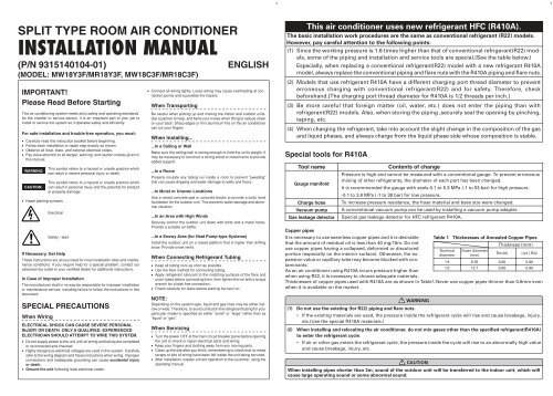
This air conditioner uses new refrigerant HFC (R410A).<br />
5 cm or over<br />
The basic installation work procedures are the same as conventional refrigerant (R22) models.<br />
However, pay careful attention to the following points:<br />
(1) Since the working pressure is 1.6 times higher than that of conventional refrigerant(R22) models,<br />
some of the piping and installation and service tools are special.(See the table below.)<br />
Especially, when replacing a conventional refrigerant(R22) model with a new refrigerant R410A<br />
model, always replace the conventional piping and flare nuts with the R410A piping and flare nuts.<br />
(2) Models that use refrigerant R410A have a different charging port thread diameter to prevent<br />
erroneous charging with conventional refrigerant(R22) and for safety. Therefore, check<br />
beforehand.[The charging port thread diameter for R410A is 1/2 threads per inch.]<br />
(3) Be more careful that foreign matter (oil, water, etc.) does not enter the piping than with<br />
refrigerant(R22) models. Also, when storing the piping ,securely seal the opening by pinching,<br />
taping, etc.<br />
(4) When charging the refrigerant, take into account the slight change in the composition of the gas<br />
and liquid phases, and always charge from the liquid phase side whose composition is stable.<br />
Special tools for R410A<br />
Tool name<br />
Gauge manifold<br />
Charge hose<br />
Vacuum pump<br />
Gas leakage detector<br />
Copper pipes<br />
Contents of change<br />
Pressure is high and cannot be measured with a conventional gauge. To prevent erroneous<br />
mixing of other refrigerants, the diameter of each port has been changed.<br />
It is recommended the gauge with seals-0.1 to 5.3 MPa (-1 to 53 bar) for high pressure.<br />
-0.1 to 3.8 MPa (-1 to 38 bar) for low pressure.<br />
To increase pressure resistance, the hose material and base size were changed.<br />
A conventional vacuum pump can be used by installing a vacuum pump adapter.<br />
Special gas leakage detector for HFC refrigerant R410A.<br />
It is necessary to use seamless copper pipes and it is desirable<br />
that the amount of residual oil is less than 40 mg/10m. Do not<br />
use copper pipes having a collapsed, deformed or discolored<br />
portion (especially on the interior surface). Otherwise, the expansion<br />
value or capillary tube may become blocked with contaminants.<br />
As an air conditioner using R410A incurs pressure higher than<br />
when using R22, it is necessary to choose adequate materials.<br />
Table 1 Thicknesses of Annealed Copper Pipes<br />
Thickness (mm)<br />
Nominal<br />
diameter<br />
Thicknesses of copper pipes used with R410A are as shown in Table1.Never use copper pipes thinner than 0.8mm even<br />
when it is available on the market.<br />
WARNING<br />
1/4<br />
1/2<br />
Outer diameter<br />
(mm)<br />
6.35<br />
12.7<br />
R410A<br />
0.80<br />
0.80<br />
[ref.] R22<br />
(1) Do not use the existing (for R22) piping and flare nuts.<br />
• If the existing materials are used, the pressure inside the refrigerant cycle will rise and cause breakage, injury,<br />
etc.(Use the special R410A materials.)<br />
(2) When installing and relocating the air conditioner, do not mix gases other than the specified refrigerant(R410A)<br />
to enter the refrigerant cycle.<br />
• If air or other gas enters the refrigerant cycle, the pressure inside the cycle will rise to an abnormally high value<br />
and cause breakage, injury, etc.<br />
CAUTION<br />
When installing pipes shorter than 3m, sound of the outdoor unit will be transferred to the indoor unit, which will<br />
cause large operating sound or some abnormal sound.<br />
0.80<br />
0.80
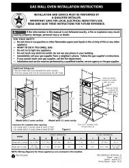
INDOOR UNIT<br />
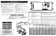
1. CUTTING THE HOLE IN THE WALL FOR THE CONNECTING PIPING<br />
(1) Cut a 3-2/16’’(80 mm) diameter hole in the wall at the position shown<br />
in (Fig.1).<br />
(2) When cutting the wall hole at the inside of the wall hook bracket,<br />
cut the hole within the range of the left and right center marks<br />
3/8’’(10 mm) below the installation frame.<br />
When cutting the wall hole at the outside of the wall hook bracket,<br />
cut the hole at least 3/8’’(10 mm) below less.<br />
(3) Cut the hole so that the outside end is lower 3/16’’ to 3/8’’ (5 to 10 mm)<br />
than the inside end.<br />
(4) Always align the center of the wall hole. If misaligned, water leakage<br />
will occur.<br />
(5) Cut the wall pipe to match the wall thickness, stick it into the wall<br />
cap, fasten the cap with vinyl tape, and stick the pipe through the<br />
hole. (The connection pipe is supplied in the installation set.)<br />
(Fig.1)<br />
(6) For left piping and right piping, cut the hole a little lower so that<br />
drain water will flow freely. (Fig.1)<br />
2. INSTALLING THE WALL HOOK BRACKET<br />
(1) Install the wall hook bracket so that it is correctly positioned horizontally<br />
and vertically. If the wall hook bracket is titled, water will<br />
drip to the floor.<br />
(2) Install the wall hook bracket so that it is strong enough to withstand<br />
the weight of an adult.<br />
●<br />
●<br />
Fasten the wall hook bracket to the wall with 6 or more screws<br />
through the holes near the outer edge of the bracket.<br />
Check that there is no rattle at the wall hook bracket.<br />
WARNING<br />
If the wall pipe is not used, the cord interconnecting<br />
the indoor and outdoor units may touch metal and<br />
cause electric leakage.<br />
3. FORMING THE DRAIN HOSE AND PIPE<br />
[Rear piping, Right piping, Bottom piping]<br />
●<br />
●<br />
●<br />
Install the indoor unit piping in the direction of the wall hole and<br />
bind the drain hose and pipe together with vinyl tape. (Fig. 3)<br />
Install the piping so that the drain hose is at the bottom.<br />
Wrap the pipes of the indoor unit that are visible from the outside<br />
with decorative tape.<br />
[For Left rear piping, Left piping]<br />
Interchange the drain cap and the drain hose.<br />
CAUTION<br />
(1) In order to align the drain hose and drain cap, be<br />
sure to insert securely and vertically. Incline insertion<br />
will cause water leakage.<br />
(2) When inserting, be sure not to attach any material<br />
besides water. If any other material is attached,<br />
it will cause deterioration and water leakage.<br />
(3) After removing drain hose, be sure not to forget<br />
mounting drain cap.<br />
(4) Be sure to fix the drain hose with tape to the bottom<br />
of piping.<br />
(5) Prevent drain water frozen under low temperature<br />
environment.<br />
When installing indoor unit's drain hose outdoors,<br />
necessary measure for frost protection should be<br />
taken to prevent drain water frozen.<br />
● Under low temperature environment (when outdoor<br />
temperature under 32 °F), after cooling operation<br />
is executed, water in the drain hose could<br />
be frozen.<br />
Once drain water is frozen, the drain hose will<br />
be blocked and water leakage may be resulted<br />
for indoor unit.<br />
Fig. 1<br />
Fasten with<br />
vinyl tape<br />
(Wall cap)<br />
Fig. 2<br />
Wall hook bracket<br />
Tapping screw<br />
Wall hook<br />
String<br />
bracket<br />
Counter weight<br />
CAUTION<br />
Center notch<br />
Hook<br />
Install the wall hook bracket horizontally and perpendicularly.<br />
Fig. 3<br />
Right piping<br />
Lower<br />
3/8’’(10 mm)<br />
or over<br />
(Wall pipe)<br />
(Inside)<br />
Bottom<br />
piping<br />
Indoor unit<br />
drain hose<br />
3-2/16’’(80 mm)<br />
dia. hole<br />
Wall<br />
Drain cap<br />
Removal method of drain<br />
hose<br />
●<br />
Remove the screw at the left of<br />
drain hose and pull out drain<br />
hose.<br />
Screw<br />
Drain fixture<br />
(blue)<br />
Drain hose<br />
Center mark<br />
3/16’’ to 3/8’’<br />
(5 to 10 mm)<br />
low<br />
(Outside)<br />
Bind with vinyl tape<br />
Pipe (top)<br />
Rear piping<br />
Indoor unit drain hose<br />
(bottom)<br />
Lower<br />
3/8’’(10 mm)<br />
or over<br />
3-2/16’’(80 mm) dia. hole<br />
(A 2-9/16’’(65mm)<br />
diameter hole is<br />
possible for the righthand<br />
side.)<br />
For left outlet piping, cut off the<br />
piping outlet cutting groove<br />
with a hacksaw.<br />
Remove the drain cap by pulling<br />
at the projection at the end of<br />
the cap with pliers, etc.<br />
<strong>Installation</strong> method of<br />
drain hose<br />
●<br />
Vertically insert the drain hose<br />
toward the inside, so that the<br />
drain fixture (blue) can accurately<br />
align with the screw hole<br />
around the drain cock.<br />
After inserting and before replacing,<br />
please reinstall and fix<br />
the removed screws.<br />
Drain fixture (blue)<br />
Screw hole<br />
Drain cock<br />
Screw<br />
Drain hose<br />
● Be sure to install around the drain hose connector.<br />
● As the screw is inside, be sure to use screwdriver treated with magnet.<br />
●<br />
●<br />
●<br />
For left piping and left rear piping, align the marks on the wall<br />
hook bracket and shape the connection pipe.<br />
Bend the connection piping at a bend radius of 2- 3/4’’(70 mm) or<br />
more and install no more than 1- 3/8’’(35 mm) from the wall.<br />
After passing the indoor piping and drain hose through the wall<br />
hole, hang the indoor unit on the hooks at the top and bottom of<br />
the wall hook bracket.<br />
[Installing the indoor unit]<br />
●<br />
●<br />
Hang the indoor unit from the hooks at the top of the wall hook<br />
bracket.<br />
Insert the spacer, etc. between the indoor unit and the wall hook<br />
bracket and separate the bottom of the indoor unit from the wall.<br />
Indoor unit<br />
Wall hook bracket<br />
(Spacer)<br />
4. CONNECTING THE PIPING<br />
CONNECTION<br />
(1) Install the outdoor unit wall cap (supplied with the optional installation<br />
set or procured at the site) to the wall pipe.<br />
(2) Connect the outdoor unit and indoor unit piping.<br />
(3) After matching the center of the flare surface and tightening the<br />
nut hand tight, tighten the nut to the specified tightening torque<br />
with a torque wrench. (Tighten the flare nut of the outdoor unit<br />
3-way valve after air purging.)<br />
FLARING<br />
(1) Cut the connection pipe to the necessary length with a pipe cutter.<br />
(2) Hold the pipe downward so that cuttings will not enter the pipe<br />
and remove the burrs.<br />
(3) Insert the flare nut onto the pipe and flare the pipe with a flaring<br />
tool.<br />
BENDING PIPES<br />
Check if [L] is flared uniformly<br />
and is not cracked or scratched.<br />
L dimension<br />
Thin pipe 1/4” (6.35 mm)dia. ...... 1/16” (1.4 to 1.7 mm)<br />
Thick pipe 1/2” (12.7 mm)dia. ...... 5/64” (1.9 to 2.2 mm)<br />
The pipes are shaped by your hands. Be careful not to collapse them.<br />
OK<br />
Extend the pipe<br />
by unwinding it.<br />
NO<br />
Do not bend the pipes in an angle more than 90°.<br />
When pipes are repeatedly bent or stretched, the material will harden,<br />
making it difficult to bend or stretch them any more. Do not bend or stretch<br />
the pipes more than three times.<br />
Fig. 4<br />
Align the marks.<br />
Bend 2-3/4’’(R70)<br />
with a pipe bender<br />
Connection pipe<br />
(1/2’’(12.7 mm) dia.)<br />
Indoor unit<br />
Fig. 5<br />
Table 2<br />
(Fitting)<br />
Top hooks<br />
Bottom hooks<br />
Wall hook<br />
bracket<br />
After hooking the indoor unit to the top hook, hook the fittings of the<br />
indoor unit to the two bottom hooks while lowering the unit and<br />
pushing it against the wall.<br />
Torque wrench<br />
Indoor unit pipe<br />
Tighten with two wrenches.<br />
Flare nut tightening torque<br />
Flare nut<br />
1/4” (6.35 mm)dia.<br />
1/2” (12.7 mm)dia.<br />
Wrench (fixed)<br />
Flare nut<br />
Connection pipe<br />
CAUTION<br />
To prevent gas leakage,<br />
coat the flare surface<br />
with refrigerator oil.<br />
Tightening torque<br />
11.57 to 13.02 ft•lbs<br />
(160 to 180 kgf•cm)<br />
36.17 to 39.78 ft•lbs<br />
(500 to 550 kgf•cm)<br />
Connection pipe<br />
(1/4” (6.35 mm) dia.)<br />
(1) Fasten a flare nut with a torque wrench as instructed in this manual. If<br />
fastened too tight, the flare nut may be broken after a long period of time<br />
and cause a leakage of refrigerant.<br />
(2) During installation, make sure that the refrigerant pipe is attached firmly<br />
before you run the compressor. Do not operate the compressor under the<br />
condition of refrigerant piping not attached properly with 2-way or 3-way<br />
valve open. This may cause abnormal pressure in the refrigeration cycle<br />
that leads to breakage and even injury.
GENERAL<br />
This INSTALLATION MANUAL briefly outlines where<br />
and how to install the air conditioning system. Please<br />
read over the entire set of instructions for the indoor<br />
and outdoor units and make sure all accessory parts<br />
listed are with the system before beginning.<br />
1. TYPE OF COPPER PIPE AND INSULATION MATERIAL<br />
Copper tubing for connectin the outdoor unit to the indoor<br />
unit and insulation material is available for purchase locally.<br />
When you purchase them, please specify the following.<br />
A. Deoxidized annealed copper pipe for refrigerant piping as:<br />
Table 3<br />
STANDARD ACCESSORIES<br />
The following installation accessories are supplied. Use them as<br />
required.<br />
INDOOR UNIT ACCESSORIES<br />
Name and Shape<br />
Wall hook bracket<br />
Remote<br />
control unit<br />
Q’ty<br />
1<br />
Name and Shape<br />
Cloth tape<br />
Tapping screw (big)<br />
Q’ty<br />
1<br />
8<br />
SELECTING THE MOUNTING<br />
POSITION<br />
Decide the mounting position with the customer as follows:<br />
1. INDOOR UNIT<br />
(1) Install the indoor unit level on a strong wall which is not subject<br />
to vibration.<br />
(2) The inlet and outlet ports should not be obstructed : the air should<br />
be able to blow all over the room.<br />
(3) Install the unit near an electric outlet or special branch circuit.<br />
(4) Do not install the unit where it will be exposed to direct sunlight.<br />
(5) Install the unit where connection to the outdoor unit is easy.<br />
(6) Install the unit where the drain pipe can be easily installed.<br />
(7) Take servicing, etc. into consideration and leave the spaces shown<br />
in (Fig. 7). Also install the unit where the filter can be removed.<br />
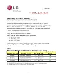
INSTALLATION DIAGRAM OF<br />
INDOOR AND OUTDOOR UNITS<br />
Fig. 7<br />
[INDOOR UNIT]<br />
2-2/5”(6 cm) or over<br />
2”(5 cm)<br />
or over<br />
Wall hook bracket<br />
3- 3/5”(9 cm)<br />
or over<br />
Small pipe<br />
Large pipe<br />
Outer diameter Thickness Outer diameter Thickness<br />
1/4”(6.35 mm) 1/32”(0.8 mm) 1/2”(12.7 mm) 1/32”(0.8 mm)<br />
Cut each pipe to the appropriate length +12” (30 cm)<br />
to16” (40 cm) to dampen vibration between units.<br />
B. Foamed polyethylene insulation for copper pipes as<br />
required to precise length of piping. Wall thickness<br />
of the insulation should not be less than 5/16” (8 mm).<br />
C. Use insulated copper wire for field wiring.<br />
CAUTION<br />
Check local electrical codes and regulations<br />
before obtaining wire. Also, check any specified<br />
instructions or limitations.<br />
2. ADDITIONAL MATERIALS REQUIRED FOR INSTALLATION<br />
A. Refrigeration (armored) tape<br />
B. Insulated staples or clamps for connecting wire<br />
(See your local electrical codes.)<br />
C. Putty<br />
D. Refrigeration lubricant<br />
E. Clamps or saddles to secure refrigerant piping<br />
3. OPERATING RANGE<br />
Table 4<br />
Cooling/Dry Mode<br />
Heating Mode<br />
Battery (penlight)<br />
Remote control<br />
unit holder<br />
Drain pipe<br />
1<br />
2<br />
1<br />
1<br />
Name<br />
Tapping screw (small)<br />
<strong>Air</strong> cleaning filter<br />
<strong>Air</strong> cleaning filter frame<br />
Seal A<br />
The following items are necessary to install this air conditioner. (The<br />
items are not included with the air conditioner and must be purchased<br />
separately.)<br />
2<br />
2<br />
2<br />
1<br />
Q’ty<br />
2. OUTDOOR UNIT<br />
(1) If possible, do not install the unit where it will be exposed to direct<br />
sunlight. (If necessary, install a blind that does not interfere<br />
with the air flow.)<br />
(2) Do not install the unit where a strong wind blows or where it is<br />
very dusty.<br />
(3) Do not install the unit where people pass.<br />
(4) Take your neighbors into consideration so that they are not disturbed<br />
by air blowing into their windows or by noise.<br />
(5) Provide the space shown in Fig. 7 so that the air flow is not blocked.<br />
Also for efficient operation, leave open three of the four directions<br />
front, rear, and both sides.<br />
WARNING<br />
Install at a place that can withstand the weight of the<br />
indoor and outdoor units and install positively so that<br />
the units will not topple or fall.<br />
CAUTION<br />
(1) Do not install where there is the danger of combustible<br />
gas leakage.<br />
(2) Do not install near heat sources.<br />
(3) If children under 10 years old may approach the<br />
unit, take preventive measures so that they cannot<br />
reach the unit.<br />
60”(150 cm) or over<br />
95” (240 cm)<br />
or over<br />
Remote<br />
control unit<br />
[OUTDOOR UNIT]<br />
4”(10 cm)<br />
or over<br />
Connection Cord<br />
14AWG<br />
12”(30 cm)<br />
or over<br />
24”(60 cm)<br />
or over<br />
(Wall cap)<br />
Remote<br />
control<br />
unit holder<br />
Tapping<br />
screw<br />
(small)<br />
4”(10 cm)<br />
or over<br />
12”(30 cm)<br />
or over<br />
Outdoor temperature<br />
Indoor temperature<br />
Indoor humidity<br />
ADDITIONAL CHARGE<br />
Refrigerant suitable for a piping length of 49 ft (15 m) is charged in<br />
the outdoor unit at the factory.<br />
When the piping is longer than 49 ft (15 m), additional charging is necessary.<br />
For the additional amount, see the table below.<br />
Table 5<br />
Pipe length<br />
Additional<br />
refrigerant<br />
49 ft (15 m)<br />
None<br />
About 14 to 115 °F<br />
About 64 to 90 °F<br />
About 80% or less<br />
66 ft (20 m)<br />
3.5 oz (100 g)<br />
About 5 to 75 °F<br />
88 °F or less<br />
Between 49 ft (15 m) and 66 ft (20 m), when using a connection pipe<br />
other than that in the table, charge additional refrigerant with 0.2 oz/<br />
ft (20g/1 m) as the criteria.<br />
CAUTION<br />
(1) When adding refrigerant, add the refrigerant from<br />
the charging port at the completion of work.<br />
(2) The maximum length of the piping is 66 ft (20 m).<br />
If the units are further apart than this, correct<br />
operation can not be guaranteed.<br />
Connection pipe assembly<br />
Connection cord (3-conductor)<br />
Wall pipe<br />
Decorative tape<br />
Vinyl tape<br />
Wall cap<br />
Saddle<br />
Drain hose<br />
Tapping screws<br />
Sealant<br />
ELECTRICAL REQUIREMENT<br />
1<br />
1<br />
1<br />
1<br />
1<br />
1<br />
1 set<br />
1<br />
1 set<br />
Always make the air conditioner power supply a special branch circuit<br />
and provide a special switch and receptacle. Do not extend the<br />
power cord.<br />
MINIMUM CIRCUIT AMPACITY<br />
CAUTION<br />
MAXIMUM OVERCURRENT PROTECTION<br />
(TIME DELAY FUSE OR HACR TYPE CIRCUIT BREAKER)<br />
16 A<br />
20 A<br />
1<br />
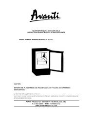
[Indoor unit piping direction]<br />
The piping can be connected in the 6 directions indicated in (Fig. 6). When<br />
the piping is connected in direction 2, 3, 4 or 5, cut along the piping<br />
groove in the side of the front cover with a hacksaw.<br />
Fig. 6<br />
2 Right outlet<br />
Fig. 8<br />
3 Bottom outlet<br />
(Rear)<br />
1 Rear outlet<br />
21-1/4” (54 cm)<br />
4 Left bottom<br />
outlet<br />
12-9/16” (32 cm)<br />
5 Left<br />
outlet<br />
6 Left rear<br />
outlet<br />
Mounting Support<br />
(Prepared On-site)<br />
[Reverse cycle only]<br />
Drain hose<br />
2”(5 cm)<br />
or over<br />
Outdoor unit bottom<br />
NOTE:<br />
In places where the outdoor temperature drops<br />
to 32°F or lower, the drain water may freeze and<br />
may stop up the drain or cause other outdoor<br />
unit trouble. Therefore take measures so that<br />
the drain water will not freeze and clog the<br />
drain.
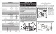
OUTDOOR UNIT<br />
OUTDOOR UNIT INSTALLATION<br />
ELECTRICAL WIRING (OUTDOOR UNIT)<br />
●<br />
●<br />
Set the unit on a strong stand, such as one made of concrete blocks<br />
to minimize shock and vibration.<br />
Do not set the unit directly on the ground because it will cause trouble.<br />
Connector cover removal<br />
●<br />
Remove the two mounting screws.<br />
Fig. 9<br />
1. Remove the screws, then remove the control box cover.<br />
2. Fasten the Inter unit wire harness and power supply to the conduit holder using the lock nut.<br />
3. Connect inter-unit wire harness and power supply to the terminal.<br />
Refer to the wiring diagram<br />
4. Use the screws to install the control box cover.<br />
Installing the connector cover<br />
(1) After inserting the three front hooks, then insert the rear hook.<br />
(2) Tighten the two mounting screws.<br />
WARNING<br />
(1) Install the unit where it will not be tilted by more<br />
than 5°.<br />
(2) When installing the outdoor unit where it may exposed<br />
to strong wind, fasten it securely.<br />
Tapping screw<br />
Front hooks<br />
Rear hooks<br />
Connector cover<br />
WARNING<br />
Be sure to comply with local codes while running<br />
the wire from the indoor unit to the outdoor<br />
unit (size of wire and wiring method, etc. ).<br />
Every wire must be connected firmly.<br />
No wire should be allowed to touch refrigerant<br />
tubing, the compressor or any moving part.<br />
NOTE:<br />
• Connector trade size for this unit is 1/2” (12.7 mm). The connector<br />
can be bought at a hardware store. Refer to “How to connect<br />
wiring to the terminals” for instructions on connecting depending<br />
on the wire type you are using.<br />
• The fuse located in the outdoor unit provides power supply protection<br />
and may blow when power is applied if the system has<br />
been incorrectly wired.<br />
AIR PURGE<br />
Always use a vacuum pump to purge the air.<br />
Refrigerant for purging the air is not charged in the<br />
outdoor unit at the factory.<br />
Close the high pressure side valve of the gauge manifold fully and do<br />
not operate it during the following work.<br />
Loose wiring may cause the terminal to overheat<br />
or result in unit malfunction. A fire hazard<br />
may also exist. Therefore, be sure all wiring is<br />
tightly connected.<br />
Connect wires to the matching numbers of<br />
terminals.<br />
Lock nut<br />
1. Check if the piping connections are secure.<br />
2. Check that the stems of 2-way valve and 3-way valve are closed<br />
fully.<br />
3. Connect the gauge manifold charge hose to the charging port<br />
of the 3-way valve (side with the projection for pushing in the<br />
valve core).<br />
4. Open the low pressure side valve of the gauge manifold fully.<br />
5. Operate the vacuum pump and start pump down.<br />
6. Slowly loosen the flare nut of the 3-way valve and check if air<br />
enters, then retighten the flare nut.<br />
(When the flare nut is loosened the operating sound of the<br />
vacuum pump changes and the reading of the compound<br />
pressure gauge goes from minus to zero.)<br />
11. Firmly tighten the 2-way valve and 3-way valve blank cap and<br />
the charging port cap.<br />
Fig. 10<br />
3-way valve<br />
Charging port cap<br />
2-way valve<br />
Gauge manifold<br />
Compound pressure gauge<br />
Flare nut<br />
Valve stem<br />
Charging port<br />
-0.1 MPa<br />
(-76 cmHg<br />
-1 bar)<br />
Low pressure<br />
side valve<br />
Blank cap<br />
Charge hose<br />
LO HI<br />
Pressure gauge<br />
High<br />
pressure<br />
side valve<br />
(closed)<br />
Charge<br />
hose<br />
Vacuum pump<br />
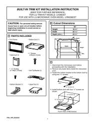
Fig. 11<br />
Indoor unit<br />
Terminal<br />
G<br />
3<br />
2<br />
1<br />
DISCONNECT<br />
SWITCH<br />
(FIELD SUPPLY)<br />
Grounding line<br />
Control line<br />
(Inter Unit)<br />
Power line<br />
208/230V<br />
208/230V<br />
208/230V<br />
Outdoor unit<br />
(L) (N)<br />
Terminal<br />
G<br />
5<br />
4<br />
1 2 3<br />
POWER SUPPLY<br />
1 phase, 208/230V<br />
Cord Clamp<br />
Conduit<br />
connector<br />
Power supply<br />
Inter-unit<br />
wire harness<br />
7. Pump down the system for at least 15 minutes, then check if the<br />
compound pressure gauge reads -0.1 MPa (-76 cmHg, -1 bar).<br />
8. At the end of pump down, close the low pressure side gauge of<br />
the gauge manifold fully and stop the vacuum pump.<br />
9. Slowly loosen the valve stem of the 3-way valve. When the<br />
compound pressure gauge reading reaches 0.1-0.2 MPa,<br />
retighten the valve stem and disconnect the charge hose<br />
from the 3-way valve charging port.<br />
(If the stem of the 3-way valve is opened fully before the<br />
charge hose is disconnected, it may be difficult to disconnect<br />
the charge hose.)<br />
Table 6<br />
Blank cap (2-way valve)<br />
Blank cap (3-way valve)<br />
Charging port cap<br />
Tightening torque<br />
14.47 to 18.08 ft•lbs (200 to 250 kgf•cm)<br />
20.25 to 23.15 ft•lbs (280 to 320 kgf•cm)<br />
9.04 to 11.57 ft•lbs (125 to 160 kgf•cm)<br />
CAUTION<br />
(1) Refrigerant must not be discharged into atmosphere.<br />
Earth screw<br />
G<br />
Indoor unit<br />
terminal block<br />
1 2 3 4<br />
Disconnect switch<br />
Outdoor unit<br />
terminal block<br />
1 2 3 4 5<br />
Earth screw<br />
G<br />
10. Fully open the valve stems of the 2-way valve and 3-way valve<br />
using a hexagon wrench. (After the valve stem begins to turn,<br />
turn it with a torque of less than 2.17ft •lbs (30 kgf•cm) until it<br />
stops turning.)<br />
(2) After connecting the piping , check the joints for<br />
gas leakage with gas leak detector.<br />
Power supply line
ELECTRICAL WIRING (INDOOR UNIT)<br />
HOW TO THE INSTALL THE INTER-UNIT WIRE HARNESS<br />
1. Remove the screws, then remove the conduit holder.<br />
2. Fasten the inter-unit wire harness to the conduit holder using the lock nut.<br />
IMPORTANT: Refer to Fig. 19 about the length of inter-unit wire harness.<br />
3. Use the screws to install the conduit holder with which Inter-unit wire harness<br />
is included.<br />
4. Remove the screws, then remove the cord clamp.<br />
5. Connect inter-unit wire harness to the terminal.<br />
Refer to the wiring diagram.<br />
6. Use the screws to install the cord clamp.<br />
Fig. 13<br />
Fig. 12<br />
Lock nut<br />
Conduit Holder<br />
Screw<br />
Conduit Connector<br />
FINISHING<br />
(1) Insulate between pipes.<br />
● For rear, right, and bottom piping, overlap the connection pipe<br />
heat insulation and indoor unit pipe heat insulation and bind<br />
them with vinyl tape so that there is no gap.<br />
● For left and left rear piping, butt the connection pipe heat insulation<br />
and indoor unit pipe heat insulation together and bind them<br />
with and vinyl tape so that there is no gap.<br />
● For left and left rear piping, wrap the area which accommodates<br />
the rear piping housing section with cloth tape.<br />
● For left and left rear piping, bind the connection cord to the top<br />
of the pipe with vinyl tape.<br />
● For left and left rear piping, bundle the piping and drain hose<br />
together by wrapping them with cloth tape over the range within<br />
which they fit into the rear piping housing section.<br />
(2) Temporarily fasten the connection cord along the connection pipe<br />
with vinyl tape. (Wrap to about 1/3 the width of the tape from the<br />
bottom of the pipe so that water does not enter.)<br />
(3) Fasten the connection pipe to the outside wall with a saddle, etc.<br />
(4) Fill the gap between the outside wall pipe hole and the pipe with<br />
sealer so that rain water and wind cannot blow in.<br />
(5) Fasten the drain hose to the outside wall, etc.<br />
Fig. 15<br />
Connection pipe<br />
(heat insulation)<br />
Pipe<br />
Indoor unit pipe (heat insulation)<br />
Vinyl tape<br />
Wrap with<br />
cloth tape<br />
Drain hose Cloth tape<br />
Connection cord<br />
Pipe<br />
Left piping<br />
Seal A<br />
Butt connection pipe (heat<br />
insulation) against the indoor<br />
unit pipe (heat insulation)<br />
and wrap with seal A so that<br />
there is no gap.<br />
Drain hose<br />
For connection from the left rear<br />
Wall pipe<br />
Connection cord<br />
Cord clamp<br />
Fig. 16<br />
Connection pipe<br />
Cord clamp<br />
(Outside wall cap)<br />
(Saddle)<br />
Drain hose<br />
(Sealer putty)<br />
Check the following:<br />
View from indoors<br />
GOOD BAD BAD BAD<br />
Screw<br />
(Outdoors)<br />
Drain hose<br />
Screw<br />
Pipe<br />
Wall<br />
Saddle<br />
Connection cord<br />
Connection cord<br />
Lifted up<br />
Wave<br />
End in water<br />
FRONT PANEL REMOVAL AND INSTALLATION<br />
HOW TO CONNECT WIRING TO THE TERMINALS<br />
A. For solid core wiring (or F-cable)<br />
(1) Cut the wire end with a wire cutter or wire-cutting pliers, then strip<br />
the insulation to about 15/16" (25 mm) to expose the solid wire.<br />
(2) Using a screwdriver, remove the terminal screw(s) on the terminal<br />
board.<br />
(3) Using pliers, bend the solid wire to form a loop suitable for the terminal<br />
screw.<br />
(4) Shape the loop wire properly, place it on the terminal board and<br />
tighten securely with the terminal screw using a screwdriver.<br />
B. For strand wiring<br />
(1) Cut the wire end with a wire cutter or wire-cutting pliers, then strip<br />
the insulation to about 3/8" (10 mm) to expose the strand wiring.<br />
(2) Using a screwdriver, remove the terminal screw(s) on the terminal<br />
board.<br />
(3) Using a round terminal fastener or pliers, securely clamp a round<br />
terminal to each stripped wire end.<br />
(4) Position the round terminal wire, and replace and tighten the terminal<br />
screw using a screwdriver.<br />
Fig. 14<br />
Strip 15/16" (25 mm)<br />
Wire<br />
A. Solid wire<br />
Insulation<br />
Loop<br />
Screw with<br />
special washer<br />
Round<br />
terminal<br />
Terminal<br />
board<br />
Wire<br />
Terminal block<br />
Strip 3/8" (10 mm)<br />
B. Strand wire<br />
Round<br />
terminal<br />
Screw with<br />
special washer<br />
Round<br />
terminal<br />
THE INTAKE GRILLE REMOVAL<br />
(1) Open the intake grille.<br />
(2) Pull down the knob.<br />
(3) Lift the intake grille upward, until the axle at the top of the intake<br />
grille is removed.<br />
THE INTAKE GRILLE INSTALLATION<br />
(1) The fixing axle of the intake grille is installed on the Panel.<br />
(2) Lay down the intake grille.<br />
THE FRONT PANEL REMOVAL<br />
(1) Remove intake grille (Reference the intake grille removal.)<br />
(2) Remove four screws.<br />
(3) The thumb is hung on the lower part as shown in the figure, and it<br />
pulls to the front, pushing [-] mark , and bottom hooks (two position)<br />
is removed from wall hook bracket.<br />
(4) The front panel bottom is pulled to the front, and bottom hooks is<br />
removed indoor unit.<br />
(5) The front panel is pulled to the front, raising the upper surface,<br />
and a front panel is removed.<br />
THE FRONT PANEL INSTALLATION<br />
(1) Firstly, fit the lower part of the front panel, and insert top and bottom<br />
hooks. (Three top sides, six bottom sides)<br />
(2) Four screws is attached.<br />
(3) The intake grille is attached.<br />
Push<br />
Fig. 17<br />
[-] mark<br />
Push<br />
Top holes (two sides)<br />
Intake grille<br />
Mounting shaft<br />
Bearing<br />
Front panel<br />
Screws<br />
(4 position)<br />
Front panel<br />
Wall hook bracket<br />
Intake grille<br />
Knob<br />
Front panel<br />
CAUTION<br />
Bottom hooks<br />
(six position)<br />
Top hole (center)<br />
Top hook (center)<br />
Front panel<br />
(1) Match the terminal block numbers and connection<br />
cord colors with those of the outdoor unit.<br />
Erroneous wiring may cause burning of the electric<br />
parts.<br />
(2) Connect the connection cords firmly to the terminal<br />
block. Imperfect installation may cause a fire.<br />
(3) Always fasten the outside covering of the connection<br />
cord with the cord clamp. (If the insulator is chafed,<br />
electric leakage may occur.)<br />
(4) Securely earth the power cord plug.<br />
(5) Do not use the earth screw for an external connector.<br />
Only use for interconnection between two units.<br />
Indoor unit<br />
Bottom hole<br />
(six position)<br />
Front panel<br />
Indoor unit<br />
Top hooks<br />
(two sides)
TEST RUNNING<br />
●<br />
●<br />
●<br />
●<br />
Perform test operation and check items 1 and 2 below.<br />
For the test operation method, refer to the operating manual.<br />
The outdoor unit, may not operate, depending on the room temperature. In this case, press the test run button on the remote control unit<br />
while the air conditioner is running, (Point the transmitter section of the remote control unit toward the air conditioner and press the test run<br />
button with the tip of a ball-point pen, etc.)<br />
To end test operation, press the remote control unit START/STOP button.<br />
(When the air conditioner is run by pressing the test run button, the OPERATION indicator lamp and TIMER indicator lamp will simultaneously<br />
flash slowly.)<br />
1. INDOOR UNIT<br />
(1) Is operation of each button on the remote control unit normal?<br />
(2) Does each lamp light normally?<br />
(3) Do the air flow-direction louver operate normally?<br />
(4) Is the drain normal?<br />
2. OUTDOOR UNIT<br />
(1) Is there any abnormal noise and vibration during operation?<br />
(2) Will noise, wind, or drain water from the unit disturb the neighbors?<br />
(3) Is there any gas leakage?<br />
POWER<br />
WARNING<br />
(1) The rated voltage of this product is 208/230 V AC<br />
60 Hz.<br />
(2) Before turning on the power, check if the voltage<br />
is within the 208 V-10% to 230V+10% range.<br />
(3) Always use a special branch circuit and install a<br />
special receptacle to supply power to the room<br />
air conditioner.<br />
(4) Use a circuit breaker and receptacle matched to<br />
the capacity of the air conditioner.<br />
(5) Do not extend the power cord.<br />
(6) Perform wiring work in accordance with standards<br />
so that the air conditioner can be operated<br />
safely and positively.<br />
(7) Install a leakage circuit breaker in accordance with<br />
the related laws and regulations and electric company<br />
standards.<br />
Transmitter section<br />
Test run button<br />
Fig. 18<br />
CAUTION<br />
(1) The power source capacity must be the sum of<br />
the air conditioner current and the current of other<br />
electrical appliances. When the current contracted<br />
capacity is insufficient, change the contracted capacity.<br />
(2) When the voltage is low and the air conditioner is<br />
difficult to start, contact the power company the<br />
voltage raised.<br />
CUSTOMER GUIDANCE<br />
Explain the following to the customer in accordance with the operating<br />
manual:<br />
(1) Starting and stopping method, operation switching, temperature<br />
adjustment, timer, air flow switching, and other remote control unit<br />
operations.<br />
(2) <strong>Air</strong> filter removal and cleaning, and how to use the air louvers.<br />
(3) Give the operating and installation manuals to the customer.<br />
The method of adjusting inter-unit wire harness<br />
To connect inter-unit wire harness to the terminal correctly, please<br />
refer to Fig. 19 to adjust the length of the part of Inter-unit Wire<br />
harness ahead from conduit holder.<br />
Fig. 19<br />
5-1/2" (140mm) 15/16" (25mm)<br />
14AWG<br />
EARTH WIRE<br />
15/16" (25mm)<br />
4-3/16" (105mm)<br />
(1:1)<br />
CONDUIT PLATE<br />
PUMP DOWN OPERATION (FORCED COOLING OPERATION)<br />
To avoid discharging refrigerant into the atmosphere at the time of relocation or disposal, recover refrigerant by doing the cooling operation or<br />
forced cooling operation according to the following procedure. (When the cooling operation cannot start in winter, and so on, start the forced<br />
cooling operation.)<br />
(1) Do the air purging of the charge hose by connecting the charging hose of gauge manifold to the charging port of 3 way valve and opening the<br />
low-pressure valve slightly.<br />
(2) Close the valve stem of 2 way valve completely.<br />
(3) Start the cooling operation or following forced cooling operation.<br />
When using the remote control unit<br />
Press the TEST RUN button after starting the cooling operation by the remote control unit.<br />
The operation indicator lamp and timer indicator lamp will begin to flash simultaneously during test run.<br />
When using the MANUAL AUTO button of the indoor unit (The remote control unit is lost, and so on.)<br />
Keep on pressing the MANUAL AUTO button of the indoor unit for more than 10 seconds.<br />
(The forced cooling operation cannot start if the MANUAL AUTO button is not kept on pressing for more than 10 seconds.)<br />
(4) Close the valve stem of 3 way valve when the reading on the compound pressure gage becomes 0.05~0 MPa (0.5~0 kg/cm 2 ).<br />
(5) Stop the operation.<br />
• Press the START/STOP button of the remote control unit to stop the operation.<br />
• Press the MANUAL AUTO button when stopping the operation from indoor unit side.<br />
(It is not necessary to press on keeping for more than 10 seconds.)<br />
CONDUIT CONNECTOR<br />
CAUTION<br />
During the pump-down operation, make sure that the compressor is turned off before you remove the refrigerant piping.<br />
Do not remove the connection pipe while the compressor is in operation with 2 way or 3 way valve open. This may cause abnormal<br />
pressure in the refrigeration cycle that leads to breakage and even injury.
REMOTE CONTROL UNIT INSTALLATION<br />
CAUTION<br />
(1) Check that the indoor unit correctly receives the<br />
signal from the remote control unit, then install<br />
the remote control unit holder.<br />
(2) Select the remote control unit holder selection<br />
site by paying careful attention to the following:<br />
Avoid places in direct sunlight.<br />
Select a place that will not be affected by the heat<br />
from a stove, etc.<br />
1. REMOTE CONTROL UNIT HOLDER INSTALLATION<br />
• Install the remote control unit with a distance of 23 ft(7<br />
m) between the remote control unit and the photocell<br />
as the criteria. However, when installing the remote control<br />
unit, check that it operates positively.<br />
• Install the remote control unit holder to a wall, pillar,<br />
etc. with the tapping screw (Fig.20).<br />
Fig. 20<br />
Remote control unit<br />
holder fixing<br />
Remote control<br />
unit holder<br />
Tapping<br />
screw<br />
(small)<br />
2 Push<br />
Remote control<br />
unit mounting<br />
1 Set<br />
Remote<br />
control unit