JLC Series, JLC680 - Coffing Hoists, Coffing Hoist Parts
JLC Series, JLC680 - Coffing Hoists, Coffing Hoist Parts
JLC Series, JLC680 - Coffing Hoists, Coffing Hoist Parts

You also want an ePaper? Increase the reach of your titles
YUMPU automatically turns print PDFs into web optimized ePapers that Google loves.
Country Club Road<br />
P.O. Box 779<br />
Wadesboro, NC 28170 USA<br />
TEL: (800) 477-5003<br />
FAX: (800) 374-6853<br />
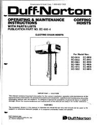
Double-Chain<br />
Only<br />
Figure 4 — Chain Replacement<br />
Diagram<br />
13. Attach the bottom block on single-chained hoists using a<br />
new load block screw (See Figure 23). On double-chained<br />
hoists, feed the chain through the load block (welds<br />
of the upstanding links will be in towards the sheave) and<br />
fasten the end of the chain to the chain support using a<br />
new chain support pin (See Figure 23). Be sure there are<br />
no twists in the chain.<br />
14. Adjust the upper limit switch (See ADJUSTING UPPER<br />
LIMIT, page 8).<br />
Chain Replacement with No Chain in <strong>Hoist</strong><br />
Refer to Figure 4.<br />
1. DISCONNECT HOIST FROM POWER SUPPLY and move<br />
hoist to a work table. Remove the electrical cover, electrical<br />
panel and the electric brake assembly.<br />
2. Detach the chain stripper from the bottom of the hoist.<br />
3. Insert the new chain between the load sheave and the chain<br />
guide. Feed the chain into the hoist by manually turning the<br />
brake hub. Allow about 15" of chain below the hoist on the<br />
slack end. Be sure the welds of the upstanding links are out<br />
away from the load sheave and that proper orientation is<br />
observed for attachment of the slack end. Also be sure the<br />
load hook assembly (if already attached to the chain) is<br />
toward the center of the hoist or to your right looking from<br />
the transmission end.<br />
There are wires running through the hoist. Carefully<br />
ease the hoist sections apart. Do not jerk them apart.<br />
4. Reinstall the chain stripper (with the chain anchor on doublechained<br />
hoists, See Figure 4) observing proper chain<br />
alignment and avoiding any twist in the chain.<br />
5. Follow steps 11 through 14 in previous section, CHAIN<br />
REPLACEMENT WITH CHAIN IN HOIST, to complete the<br />
chain replacement procedure.<br />
NOTE: Inspect chain guides and load sheave for wear,<br />
replace as needed.<br />
LIMIT SWITCH ADJUSTMENT<br />
IMPORTANT: Before placing hoist in operation, check the limit<br />
switch adjustment. Limit switches are provided to protect the<br />
hoist against damage resulting from overtravel or to allow setting<br />
the hook travel within the factory-set limits of travel. The standard<br />
limit switch is designed for lifts of 50 ft or less on single-chained<br />
hoists and 25 ft or less on the 2 ton, double-chained models. The<br />
long lift limit switch allows for the maximum amount of lift, which<br />
is 134 ft on 1/2 ton and under models, 143 ft on the 1 ton<br />
models, and 71 ft on the 2 ton models.<br />
The upper and lower limit switch adjusting nuts are color-coded<br />
gold and silver respectively. Each limit nut has 10 slots for fine<br />
adjustment, and the increment of adjustment is such that one<br />
slot is equivalent to approximately one link of chain travel with<br />
the standard limit switch. Movement of the limit switch nuts<br />
toward or away from each other increases or decreases the<br />
hook travel respectively.<br />
Adjusting Upper Limit (Gold Nut)<br />
Refer to Figure 3.<br />
1. Suspend the hoist. For single chain models raise the load<br />
block until there is a minimum clearance of 2" from the hoist<br />
housing and the top of the block. Double chain models<br />
require a minimum clearance of 1" from the chain support to<br />
the top of the load block.<br />
2. DISCONNECT HOIST FROM POWER SUPPLY and<br />
remove the electrical cover.<br />
3. With a screwdriver, pry the spring guide plate out of the slots<br />
in the limit switch nuts.<br />
4. Turn the slotted gold nut toward its limit switch until the<br />
switch “clicks” then turn two slots farther. Release the spring<br />
guide plate and be sure it slips back into the slots in both<br />
limit switch nuts. Do not disturb the silver slotted nut if it has<br />
been set previously.<br />
Adjusting Lower Limit (Silver Nut)<br />
Refer to Figure 3.<br />
1. Suspend the hoist. Carefully lower the load block to a point<br />
where the slack-end loop of the chain hangs down 6" or<br />
more from the hoist housing (or the limit desired in any<br />
particular application allowing the minimum 6"). There<br />
should be a minimum clearance of 1½" between the chain<br />
stop and bottom of hoist.<br />
2. DISCONNECT HOIST FROM POWER SUPPLY and<br />
remove the electrical cover.<br />
3. With a screwdriver, pry the spring guide plate out of the slots<br />
in the limit switch nuts.<br />
4. Turn the slotted silver nut toward its limit switch until the<br />
switch “clicks,” then turn two slots farther. Release the spring<br />
guide plate and be sure it slips back in the slots in both limit<br />
switch nuts. Do not disturb the gold slotted nut if it has been<br />
set previously.<br />
If the wires running to the limit switches are ever<br />
disconnected for any purpose, be sure to replace<br />
wires in accordance with the correct wiring diagram<br />
(See Figures 9A, 9B, 9C & 9D).<br />
8