

O Scale Trains Magazine Online
O Scale Trains Magazine Online
O Scale Trains Magazine Online

Create successful ePaper yourself
Turn your PDF publications into a flip-book with our unique Google optimized e-Paper software.
earing hinges from the scoop assembly, namely a Dremel (or<br />
similar) tool with a thin cutoff wheel or circular saw blade. A<br />
4<br />
fixed model saw, or circular-type saw with a two inch Gyros<br />
blade attached works, too. The idea here is to preserve the maximum<br />
thickness on the side bearing hinge assembly, because it<br />
will be used in the future. It is also necessary to get an precise<br />
parallel cut along the long axis on the scoop. The Gyros blades<br />
are approximately 0.007” thick, whereas Dremel’s small cutoff<br />
wheel, in its virgin state, is 0.022” thick. I like to save my old<br />
Dremel cutoff wheels that have been “pre thinned” by side cutting<br />
in a polishing mode. These can be thinned down to 0.018”,<br />
which is sufficient for this project. For better control while cutting<br />
the scoop assembly, solder it to a brass plate. This, in turn, is<br />
used to fixture the assembly for cutting, whether using a Dremel<br />
tool or a fixed circular saw. The idea here is to have as many fingers<br />
after the cut as you had before the cut. Figure 1 shows both<br />
the scoop assembly and the bottom plate control rod assembly<br />
before and after cutting.<br />
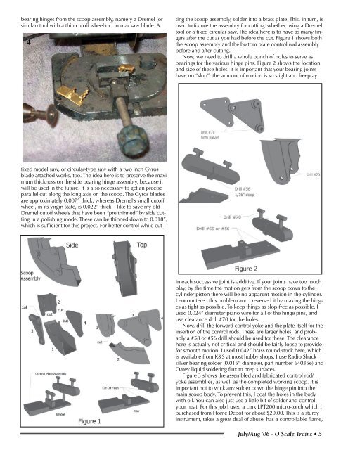
Now, we need to drill a whole bunch of holes to serve as<br />
bearings for the various hinge pins. Figure 2 shows the location<br />
and size of these holes. It is important that your bearing joints<br />
have no “slop”; the amount of motion is so slight and freeplay<br />
in each successive joint is additive. If your joints have too much<br />
play, by the time the motion gets from the scoop down to the<br />
cylinder piston there will be no apparent motion in the cylinder.<br />
I encountered this problem and I reversed it by making the hinges<br />
as tight as possible. To keep things as slop-free as possible, I<br />
used 0.024” diameter piano wire for all of the hinge pins, and<br />
use clearance drill #70 for the holes.<br />
Now, drill the forward control yoke and the plate itself for the<br />
insertion of the control rods. These are larger holes, and probably<br />
a #58 or #56 drill should be used for these. The clearance<br />
here is actually not critical and should be fairly loose to provide<br />
for smooth motion. I used 0.042” brass round stock here, which<br />
is available from K&S at most hobby shops. I use Radio Shack<br />
silver bearing solder (0.015” diameter, part number 64035e) and<br />
Oatey liquid soldering flux to prep surfaces.<br />
Figure 3 shows the assembled and fabricated control rod/<br />
yoke assemblies, as well as the completed working scoop. It is<br />
important not to wick any solder down the hinge pin into the<br />
main scoop body. To prevent this, I coat the holes in the body<br />
with oil. You can also just use a little bit of solder and control<br />
your heat. For this job I used a Link LPT200 micro-torch which I<br />
purchased from Home Depot for about $20.00. This is a sturdy<br />
instrument, takes a great deal of abuse, has a controllable flame,<br />
July/Aug ’06 - O <strong>Scale</strong> <strong>Trains</strong> •


