


You also want an ePaper? Increase the reach of your titles
YUMPU automatically turns print PDFs into web optimized ePapers that Google loves.
Spring Loaded Power Pickup<br />
Ray Grosser<br />
General<br />
While installing a dedicated DCC system in a MTH 2-Rail<br />
2-8-0, I discovered that the locomotive did not have electrical<br />
power pickup on the drivers. I wanted as much electrical<br />
contact with the rails possible instead of having only two<br />
axles on the tender picking up from each rail. Some kind of<br />
power pickup was needed. After experimenting with phosphor<br />
bronze wire and sheet stock, I opted to build an isolated<br />
spring-loaded pin that would contact the inside of the<br />
non-insulated driver, similar to the Atlas RS-1. I first thought<br />
of fabricating the wiper pin from a 2-56 bolt with a spring<br />
on it, but that was unsatisfactory because the threads on the<br />
bolt interfered with the movement of the spring. So I started<br />
experiments with plastic tubing, brass tubing, and brass rod.<br />
First, I had to find a suitable spring. I found the one I<br />
needed in a Kadee® G gauge coupler package. It is made<br />
of bronze and is used as the draft gear spring for the coupler<br />
shank. It is perfect for this wiper installation. Here is how I<br />
did it.<br />
Fabrication<br />
I found some 0.072” brass rod in my accumulation of<br />
brass off-cuts. The 0.072” X 1/2” long rod will be used for<br />
the shaft of the assembly.<br />
Cut a piece of 1/8” (0.125”) dia. brass tubing approximately<br />
1/8” long. Apply soldering flux to the rod and the inside of<br />
the tube and tin the rod with solder. Slip the rod into the tube<br />
so the end of the rod sticks out a little on the other end and<br />
solder the two pieces together, filling the void completely.<br />
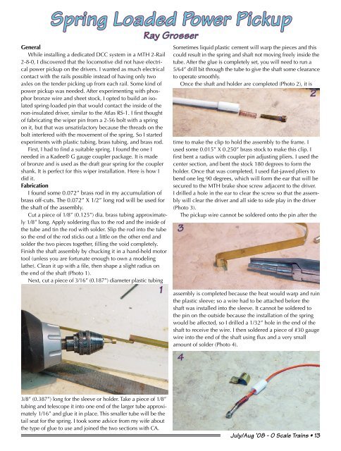
Finish the shaft assembly by chucking it in a hand-held motor<br />
tool (unless you are fortunate enough to own a modeling<br />
lathe). Clean it up with a file, then shape a slight radius on<br />
the end of the shaft (Photo 1).<br />
Next, cut a piece of 3/16” (0.187”) diameter plastic tubing<br />
1<br />
Sometimes liquid plastic cement will warp the pieces and this<br />
could result in the spring and shaft not moving freely inside the<br />
tube. After the glue is completely set, you will need to run a<br />
5/64” drill bit through the tube to give the shaft some clearance<br />
to operate smoothly.<br />
Once the shaft and holder are completed (Photo 2), it is<br />
2<br />
time to make the clip to hold the assembly to the frame. I<br />
used some 0.015” X 0.250” brass stock to make this clip. I<br />
first bent a radius with coupler pin adjusting pliers. I used the<br />
center section, and bent the stock 180 degrees to form the<br />
holder. Once that was completed, I used flat-jawed pliers to<br />
bend one leg 90 degrees, which will form the ear that will be<br />
secured to the MTH brake shoe screw adjacent to the driver.<br />
I drilled a hole in the ear to clear the screw so that the assembly<br />
will clear the driver and all side to side play in the driver<br />
(Photo 3).<br />
The pickup wire cannot be soldered onto the pin after the<br />
3<br />
assembly is completed because the heat would warp and ruin<br />
the plastic sleeve; so a wire had to be attached before the<br />
shaft was installed into the sleeve. It cannot be soldered to<br />
the pin on the outside because the installation of the spring<br />
would be affected, so I drilled a 1/32” hole in the end of the<br />
shaft to receive the wire. I then soldered a piece of #30 gauge<br />
wire into the end of the shaft using flux and a very small<br />
amount of solder (Photo 4).<br />
4<br />
3/8” (0.387”) long for the sleeve or holder. Take a piece of 1/8”<br />
tubing and telescope it into one end of the larger tube approximately<br />
1/16” and glue it in place. This smaller tube will be the<br />
tail seat for the spring. I took some advice from my wife about<br />
the type of glue to use and joined the two sections with CA.<br />
July/Aug ’08 - O <strong>Scale</strong> <strong>Trains</strong> • 13


