GL4024 - DSL electronic ® GmbH
GL4024 - DSL electronic ® GmbH
GL4024 - DSL electronic ® GmbH

Create successful ePaper yourself
Turn your PDF publications into a flip-book with our unique Google optimized e-Paper software.
Product Description<br />
Tel.: 49 2162 40025<br />
Fax: 49 2162 40035<br />
info@dsl-<strong>electronic</strong>.de<br />
www.dsl-<strong>electronic</strong>.de<br />
<strong>DSL</strong><br />
<strong>electronic</strong> ®<br />
<strong>GmbH</strong><br />
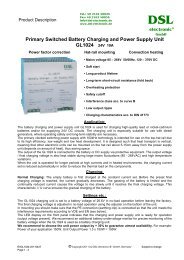
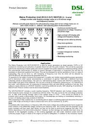
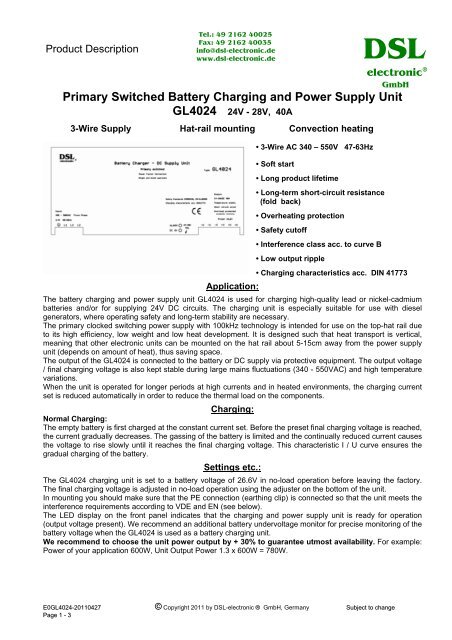
Primary Switched Battery Charging and Power Supply Unit<br />
<strong>GL4024</strong> 24V - 28V, 40A<br />
3-Wire Supply Hat-rail mounting Convection heating<br />
• 3-Wire AC 340 – 550V 47-63Hz<br />
• Soft start<br />
• Long product lifetime<br />
• Long-term short-circuit resistance<br />
(fold back)<br />
• Overheating protection<br />
• Safety cutoff<br />
• Interference class acc. to curve B<br />
• Low output ripple<br />
• Charging characteristics acc. DIN 41773<br />
Application:<br />
The battery charging and power supply unit <strong>GL4024</strong> is used for charging high-quality lead or nickel-cadmium<br />
batteries and/or for supplying 24V DC circuits. The charging unit is especially suitable for use with diesel<br />
generators, where operating safety and long-term stability are necessary.<br />
The primary clocked switching power supply with 100kHz technology is intended for use on the top-hat rail due<br />
to its high efficiency, low weight and low heat development. It is designed such that heat transport is vertical,<br />
meaning that other <strong>electronic</strong> units can be mounted on the hat rail about 5-15cm away from the power supply<br />
unit (depends on amount of heat), thus saving space.<br />
The output of the <strong>GL4024</strong> is connected to the battery or DC supply via protective equipment. The output voltage<br />
/ final charging voltage is also kept stable during large mains fluctuations (340 - 550VAC) and high temperature<br />
variations.<br />
When the unit is operated for longer periods at high currents and in heated environments, the charging current<br />
set is reduced automatically in order to reduce the thermal load on the components.<br />
Charging:<br />
Normal Charging:<br />
The empty battery is first charged at the constant current set. Before the preset final charging voltage is reached,<br />
the current gradually decreases. The gassing of the battery is limited and the continually reduced current causes<br />
the voltage to rise slowly until it reaches the final charging voltage. This characteristic I / U curve ensures the<br />
gradual charging of the battery.<br />
Settings etc.:<br />
The <strong>GL4024</strong> charging unit is set to a battery voltage of 26.6V in no-load operation before leaving the factory.<br />
The final charging voltage is adjusted in no-load operation using the adjuster on the bottom of the unit.<br />
In mounting you should make sure that the PE connection (earthing clip) is connected so that the unit meets the<br />
interference requirements according to VDE and EN (see below).<br />
The LED display on the front panel indicates that the charging and power supply unit is ready for operation<br />
(output voltage present). We recommend an additional battery undervoltage monitor for precise monitoring of the<br />
battery voltage when the <strong>GL4024</strong> is used as a battery charging unit.<br />
We recommend to choose the unit power output by + 30% to guarantee utmost availability. For example:<br />
Power of your application 600W, Unit Output Power 1.3 x 600W = 780W.<br />
E0<strong>GL4024</strong>-20110427 © Copyright 2011 by <strong>DSL</strong>-<strong>electronic</strong> ® <strong>GmbH</strong>, Germany Subject to change<br />
Page 1 - 3
Series / Parallel Connection:<br />
The output current can be increased by connecting <strong>GL4024</strong> units in parallel (no battery charging and no<br />
maximal load). Parallel connecting of different types of units are not allowed. In order to ensure correct parallel<br />
operation, the open load voltage must be set to same values. Series connecting of units are only allowed with<br />
additional current limitation up to rated current (no maximal load).<br />
Technical Data :<br />
Type Final charging Current AC Current Fusing Weight Dimensions<br />
Voltage Range Max. on mains (max) Prim. (Q1) Sec. (Q2) ( mm , W x H x D)<br />
acc. to EN60 898<br />
<strong>GL4024</strong> 24 - 28V 40A 2,4A (400V) 10A B (400V) 50A B 3,3kg 276x125,2x100<br />
1,9A (500V)<br />
Mounting<br />
: 35mm Hat rail TS-35/7,5 or 15mm<br />
Supply<br />
: 340 – 550V 47 – 63Hz<br />
Inrush consumption max. : 50A/400VAC<br />
Lost current<br />
:
E0<strong>GL4024</strong>-20110427 © Copyright 2011 by <strong>DSL</strong>-<strong>electronic</strong> ® <strong>GmbH</strong>, Germany Subject to change<br />
Page 3 - 3