Instruction Manual - Minicars
Instruction Manual - Minicars
Instruction Manual - Minicars

You also want an ePaper? Increase the reach of your titles
YUMPU automatically turns print PDFs into web optimized ePapers that Google loves.
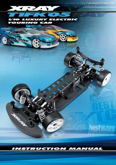
XRAY T1 Factory Kit 2005<br />
The new XRAY T1 Factory Kit '05 (T1FK'05) is the 5th generation of<br />
XRAY's extremely successful T1 family of 1/10-scale on -road electric<br />
touring cars. The T1FK'05 is a large evolutionary leap forward,<br />
blending a brand new chassis platform and completely redesigned<br />
drive train with race-proven geometry. The extraordinary materials<br />
and racecar lineage combine to offer a responsive ride, luxurious<br />
elegant design, finest quality, and best track performance. With the<br />
highest number of adjustments to achieve the most performance<br />
out of any track condition, the T1FK'05 is a top-competition racecar<br />
of the next level of performance.<br />
The T1FK'05 is the best-balanced touring car with the world's<br />
narrowest chassis. The new optimized layout concentrates more<br />
weight closer to the centerline of the chassis, giving improved<br />
traction, cornering speed, and steering on all surfaces. The<br />
redesigned drive train achieves even higher efficiency. The<br />
super-efficient C-hub suspension is retained from the predecessor<br />
T1 Factory Kit, using short-arm suspension components for superb<br />
handling.<br />
Many new and updated features are present on the T1FK'05 to<br />
optimize performance, while reducing unnecessary weight and<br />
rotating mass without compromising strength and long life. All<br />
of these components combine to make the highest-performance,<br />
best-handling electric touring car in the world.<br />
We have made every effort to make these instructions as easy to<br />
understand as possible. However, if you experience any difficulties<br />
or problems with this product, or have any questions, please<br />
contact the XRAY support team at support@teamxray.com and we<br />
will be very happy to assist you. Please visit our official Web site at<br />
www.teamxray.com, where you will find all the latest updates, setup<br />
information, option parts, and many other goodies.<br />
We at XRAY take great pride on providing the best possible service<br />
and car to all of our customers.<br />
R/C & BUILDING TIPS<br />
• Read and fully understand the instruction manual before<br />
building.<br />
• Always keep this instruction manual ready at hand for quick<br />
reference, even after completing the assembly.<br />
• Clear a work area for assembling the kit.<br />
• Work on a light-colored towel so any dropped parts are easy<br />
to find.<br />
• Only open bags of parts for the assembly section you are<br />
building; do not open parts bags before required.<br />
• Make sure all screws are tight, and check them periodically.<br />
Make sure the chassis screws do not protrude below the<br />
chassis.<br />
• For best performance, it is very important to ensure the free<br />
movement of all parts.<br />
• Tap or pre-thread composite parts when threading screws.<br />
• Self-tapping screws cut threads into the parts when tightened.<br />
Do not use excessive force when tightening self-tapping screws,<br />
or you may strip out the thread in the plastic. We recommend<br />
you stop tightening a screw when you feel some resistance.<br />
• Use medium-grade (blue) threadlock on screws that thread into<br />
metal parts.<br />
Please support your local hobby shop, and ask them for<br />
advice. We at XRAY Model Racing Cars support all local hobby<br />
dealers. We ask you to purchase XRAY products at your hobby<br />
dealer whenever possible, and give them your support as we<br />
do. If you have difficulty finding XRAY products, please visit us<br />
at www.teamxray.com for advice, or contact us via e-mail at<br />
support@teamxray.com, or contact the XRAY distributor in your<br />
country.<br />
ADDITIONAL ITEMS REQUIRED:<br />
Radio system (transmitter and receiver), steering servo, speed controller, motor, pinion gear,<br />
battery pack (6-cell), battery charger, 1/10-scale bodyshell (190 mm), tires, inserts, highstrength<br />
fibre tape, double-sided tape, CA glue, bearing oil, medium-grade (blue) threadlock.<br />
Receiver Steering Servo Speed Controller<br />
190mm Bodyshell<br />
Fibre Tape<br />
Tire Inserts<br />
Tires<br />
Electric Motor<br />
6-cell Battery Pack<br />
(Inline)<br />
Pinion Gear<br />
and Setscrew<br />
TOOLS REQUIRED:<br />
Cutting Pliers, Needlenose Pliers, Snap Ring Pliers, Allen Wrenches (1.5 mm, 2.0 mm, 2.5 mm, and 3.0 mm), Hobby Knife, Caster Clip Removal Tool,<br />
Turnbuckle Wrench, Shock Assembly Tool, Vernier Calipers (digital recommended), Soldering Iron and Solder.<br />
For ease of assembly, we strongly recommend using high-quality HUDY tools. Visit www.hudy.net for more information on the entire range of HUDY products.<br />
In line with our policy of continuous product development, the exact specifications of the kit may vary. In the unlikely<br />
event of any problems with your new kit, you should contact the model shop were you purchased it, quoting the part<br />
number. We reserve all rights to change any specification without prior notice. All rights reserved.<br />
1
CONTENTS<br />
0. KIT 2<br />
1. BALL DIFFERENTIAL & FRONT MULTI-DIFF 3-4<br />
2. REAR TRANSMISSION 5-6<br />
3. REAR SUSPENSION 7-8<br />
4. FRONT TRANSMISSION 9-10<br />
5. FRONT SUSPENSION 11-12<br />
6. STEERING 13-14<br />
7. SHOCK ABSORBERS 15-16<br />
8. REAR ASSEMBLY 17<br />
FRONT ASSEMBLY 18<br />
9. FINAL ASSEMBLY 19<br />
ACCESSORY ASSEMBLY 20-21<br />
BEFORE YOU START<br />
At the beginning of each section is an exploded view of the parts to be<br />
assembled. There is also a list of all the parts and part numbers that are<br />
related to the assembly of that section.<br />
The part descriptions are color-coded to make it easier for you to identify the<br />
source of a part. Here are what the different colors mean:<br />
STYLE A - indicates parts that are included in the bag marked<br />
for the section.<br />
STYLE B - indicates parts that were set aside in Section 0.<br />
STYLE C - indicates parts that are already assembled from<br />
previous steps.<br />
0. KIT (FACTORY PRE-ASSEMBLED)<br />
904306<br />
301164<br />
FRONT<br />
302002<br />
302002<br />
301112<br />
302002<br />
960030<br />
301200<br />
904306<br />
302002<br />
904308<br />
904306<br />
KIT<br />
30 1112 6-CELL CHASSIS T1FK'05 - CNC MACHINED<br />
30 1164 UPPER DECK T1FK'05 - CNC MACHINED<br />
30 1200 COMPOSITE BUMPER<br />
30 2002 ALU SUSP. ADJUSTABLE BULKHEADS T1FK'05 (4)<br />
90 4306 HEX SCREW SFH M3x6 - SILVER (10)<br />
90 4308 HEX SCREW SFH M3x8 - SILVER (10)<br />
96 0030 NUT M3 (10)<br />
The XRAY T1FK'05 comes partially pre-assembled. Before starting assembly, disassemble the chassis parts, noting the position and orientation of the parts, particularly<br />
the bulkheads. Keep the parts, including the screw hardware, close at hand. In the assembly steps that follow, each section begins with a parts list. Parts indicated<br />
with style B are from the previously disassembled chassis parts in section 0.<br />
2
1. BALL DIFFERENTIAL & FRONT MULTI-DIFF<br />
BALL DIFFERENTIAL<br />
930508<br />
305002<br />
305082<br />
930120<br />
305050<br />
305082<br />
966080<br />
963030<br />
930138<br />
305002<br />
305040<br />
305050<br />
305050<br />
981212<br />
902305<br />
305131<br />
305150<br />
305150<br />
305131<br />
970100<br />
FRONT MULTI-DIFF<br />
NOT INCLUDED IN US KITS<br />
309319<br />
305102<br />
305150<br />
309319<br />
BAG<br />
30 5002 BALL DIFF. WITH LABYRINTH COVERS - (FACTORY KIT)<br />
30 5040 SCREW FOR EXTERNAL DIFF ADJUSTMENT - SPRING STEEL<br />
30 5050 DIFF PULLEY 34T WITH LABYRINTH DUST COVERS<br />
30 5082 DIFF WASHER 17x23x1 (2)<br />
30 5102 XRAY MULTI-DIFF T1FK'05<br />
30 5131 INNER DRIVESHAFT ADAPTER - T1FK'05 - SPRING STEEL (2)<br />
30 5150 TIMING BELT PULLEY 34T<br />
30 9319 UNIVERSAL SET OF PLASTIC SHIMS<br />
90 2305 HEX SCREW SH M3x5 (10)<br />
93 0120 CARBIDE BALL 2.4 MM FOR BALL DIFFERENTIAL (12)<br />
93 0138 CARBIDE BALL-BEARING AXIAL F3-8 3 x 8 x 3.5<br />
93 0508 BALL-BEARING MR85ZZ 5x8x2.5 (2)<br />
96 3030 CONE WASHER ST 3x8x0.5 (10)<br />
96 6080 CH-CLIP 8 (10)<br />
97 0100 O-RING 10x1.5 (10)<br />
98 1212 PIN 2x11.8 (10)<br />
Properly functioning differentials and axles are extremely important to the performance of the car. It is imperative they operate smoothly after<br />
assembly or rebuilding, and after every run. The T1FK'05 uses an adjustable ball differential and a Front Multi-Diff (non-US kits only). The ball<br />
differential is pre-assembled at the factory; follow the procedures in this section if you need to clean or rebuild the ball differential.<br />
966080<br />
C 8<br />
963030<br />
ST 3x8<br />
930138<br />
BA 3x8<br />
The ball differential is pre-assembled at the factory.<br />
Follow these steps if you need to clean or rebuild the long diff shaft assembly.<br />
1. Insert the smaller of the two thrust washers into the long diff shaft.<br />
2. Apply grease to the balls in the thrust ball cage; coat each side.<br />
Insert the thrust ball cage into the long diff shaft.<br />
3. Place the larger thrust washer into the long diff shaft.<br />
4. Insert four cone washers as shown in the detail image.<br />
5. Insert a #966080 (C 8) clip into the groove inside the<br />
long diff shaft. Use snap-ring pliers for easy assembly.<br />
➍<br />
➌<br />
3.2 mm 3.0 mm<br />
8.0 mm<br />
7.8 mm<br />
➋<br />
➊<br />
FACTORY PREASSEMBLED<br />
LONG DIFF SHAFT<br />
The ball differential is pre-assembled at the factory.<br />
Follow these steps if you need to clean or rebuild the short diff shaft assembly.<br />
➌<br />
➍<br />
930508<br />
BB 5x8<br />
1. If you need to replace the diff locknut, push it out from the opposite side with the tip of a<br />
wrench. Insert a new one into the short diff shaft.<br />
2. Place a #930508 (BB 5x8) ball-bearing on the short center stub of the short diff shaft.<br />
3. Put a very thin coat of grease on the side of a #305082 diff washer,<br />
and place it on the short diff shaft. The washer should seat centered<br />
on the short diff shaft, and the layer of grease will hold it in place.<br />
4. Press the #305050 diff pulley onto the ball-bearing.<br />
➊<br />
FACTORY PREASSEMBLED<br />
➋<br />
SHORT DIFF SHAFT<br />
930120<br />
B 2.4<br />
The ball differential is preassembled at the factory.<br />
Follow these steps if you need to clean or rebuild the diff pulley or diff balls.<br />
1. Apply a little bit of grease into each of the 12 holes in the diff pulley.<br />
2. Place the twelve #930120 carbide diff balls into the diff pulley holes.<br />
➋<br />
➊<br />
GREASE<br />
3
BALL DIFFERENTIAL & FRONT MULTI-DIFF<br />
The ball differential is pre-assembled at the factory.<br />
Follow these steps if you need to clean or rebuild the ball differential.<br />
➌<br />
930508<br />
BB 5x8<br />
1. Hold the short diff shaft with the installed pulley facing up. Place a #930508 (BB 5x8)<br />
ball-bearing on the center stub, atop the other bearing.<br />
2. Put a very thin coat of grease on the side of a #305082 diff washer, and place it on<br />
the long diff shaft. The washer should seat centered on the long diff shaft, and the layer<br />
of grease will hold it in place.<br />
3. Insert the #305040 diff screw into the top of the long diff shaft as shown, and align<br />
the holes in the screw with the holes in the diff shaft. Slide a small Allen wrench through<br />
the aligned holes in both pieces. The end of the diff screw should protrude from the<br />
center of the diff shaft.<br />
4. Hold the lower diff half upward as shown, and lower the long diff shaft with the screw<br />
pointing down onto the short diff shaft. Carefully thread the diff screw into the center of<br />
the short diff shaft. Keep tightening until the diff washer just touches the diff balls, and<br />
then tighten another 1/4 turn or until you feel some resistance. Remove the Allen wrench.<br />
➊<br />
➍<br />
➋<br />
➌<br />
LONG DIFF SHAFT<br />
Cutaway view<br />
ALWAYS HOLD THE DIFFERENTIAL VERTICAL DURING ASSEMBLY, SO THE<br />
PARTS STAY IN ALIGNMENT AND THE DIFF BALLS DO NOT FALL OUT.<br />
SHORT DIFF SHAFT<br />
To check the differential:<br />
Slide two wrenches into the slots on both sides of the diff shafts. Hold both<br />
wrenches in one hand and try to turn the pulley; it should take some force to<br />
get the pulley to slip between the two outdrives. Then remove both wrenches<br />
and rotate one of the diff shafts while holding the pulley stationery. The action<br />
should feel smooth.<br />
To tighten the differential:<br />
Insert a small Allen wrench into the aligned holes in the setscrew and long<br />
diff shaft. Turn the long diff shaft 1/16 to 1/8 of a turn clockwise to tighten.<br />
Remove the Allen wrench and recheck the diff.<br />
To loosen the differential:<br />
Same as tightening the differential, except turn the long diff shaft counter-clockwise to loosen.<br />
DO NOT TIGHTEN THE DIFF COMPLETELY<br />
THE DIFF MUST BE BROKEN IN PROPERLY !<br />
IMPORTANT: When you build the differential, do not tighten it fully initially; the differential needs to be broken in properly. When you build the diff<br />
tighten it very gently. When you put the diff in the car and complete the assembly, run the car for a few minutes, tighten the diff a little bit, and then<br />
recheck the diff. Repeat this process several times until you have the diff tightened to the point you want it.<br />
Final adjustments should ALWAYS be made with the diff in the car and on the track.<br />
Slide two Labyrinth Dust Covers onto the ends of the diff shafts; the smooth<br />
sides of the covers face outward, away from the pulley. Squeeze the covers<br />
firmly until they both "snap" onto pulley; it may take a bit of effort to do this.<br />
Once snapped on, the covers seat perfectly.<br />
FRONT MULTI-DIFF (not included in US kits)<br />
902305<br />
SH M3x5<br />
LONG SHORT<br />
309319<br />
SHIM 6x9x2<br />
981212<br />
P 2x12<br />
970100<br />
O 10x1.5<br />
NOTE ORIENTATION<br />
Hole on the pulley and on<br />
the axle must be aligned.<br />
DETAIL<br />
Attach the #305150 pulley to the #305102<br />
front axle using three #902305 (SH M3x5)<br />
screws.<br />
Attach pulley to SHORT side of front axle,<br />
opposite to side with hole through axle (for<br />
locking pin).<br />
Slide #309319 spacer onto #305131<br />
outdrive shaft.<br />
Apply one-way lube to outdrive shaft, then<br />
slide into one-way bearing in end of front<br />
axle.<br />
Repeat for other side.<br />
DIRECTION OF TURN<br />
Slide two pulley covers onto the ends of the<br />
front axle. Squeeze the covers firmly until<br />
they both "snap" over the pulley; it may take<br />
a bit of effort to do this.<br />
Verify that the outdrives rotate in the<br />
direction shown.<br />
See page 22 for front Multi-Diff settings.<br />
4
2. REAR TRANSMISSION<br />
965050 305575 981210<br />
305002 305442<br />
941015<br />
305431<br />
305516<br />
305784<br />
305787 (OPTION)<br />
305790 (OPTION)<br />
940509<br />
902305<br />
940610<br />
302070 302074<br />
902312<br />
302040<br />
302080<br />
309319<br />
307312<br />
901408<br />
302032<br />
302070 902310<br />
901308<br />
301112<br />
302002<br />
302040<br />
309319<br />
303159<br />
302032<br />
904306<br />
904306<br />
BAG<br />
02<br />
30 2032 ALU NUT FOR SUSP. PIVOT PIN (2)<br />
30 2040 LOWER SUSPENSION HOLDER ( SET 2+1+1)<br />
30 2070 ECCENTRIC NYLON HUB FOR BULKHEAD + COVERS (4+2)<br />
30 2074 ECCENTRIC REAR NYLON HUBS 0° & 2°<br />
30 2080 CASTER CLIPS SET 4+3+2+1 MM (2)<br />
30 3159 SHORT SUSPENSION ARM - REAR LOWER - C-HUB<br />
30 5431 HIGH-PERFORMANCE KEVLAR DRIVE BELT FRONT 3 x 507 MM<br />
30 5442 HIGH-PERFORMANCE KEVLAR DRIVE BELT REAR 3 x 180 MM<br />
30 5516 ALU SOLID LAYSHAFT T1FK'05<br />
30 5575 FIXED PULLEY 20T (2)<br />
30 5784 SPUR GEAR 84T / 48<br />
30 5787 SPUR GEAR 87T / 48 (OPTION)<br />
30 5790 SPUR GEAR 90T / 48 (OPTION)<br />
30 7312 REAR WISHBONE PIVOT PIN BOTTOM T1FK'05 - C-HUB (2)<br />
30 9319 UNIVERSAL SET OF PLASTIC SHIMS<br />
94 0509 HIGH-SPEED BALL-BEARING MR95ZZ 5 x 9 x 3 RUBBER COVERED (2)<br />
94 0610 HIGH-SPEED BALL-BEARING MR106ZZ 6 x 10 x 3 RUBBER COVERED (2)<br />
94 1015 HIGH-SPEED BALL-BEARING 10 x 15 x 4 RUBBER COVERED (2)<br />
90 2305 HEX SCREW SH M3x5 (10)<br />
90 2310 HEX SCREW SH M3x10 (10)<br />
90 2312 HEX SCREW SH M3x12 (10)<br />
90 4306 HEX SCREW SFH M3x6 - SILVER (10)<br />
90 1308 HEX SCREW SB M3x8 (10)<br />
90 1408 HEX SCREW SB M4x8 (10)<br />
96 5050 E-CLIP 5 (10)<br />
98 1210 PIN 2x10 (10)<br />
30 1112 6-CELL CHASSIS T1FK'05 - CNC MACHINED<br />
30 2002 ALU SUSP. ADJUSTABLE BULKHEADS T1FK'05 (4)<br />
90 4306 HEX SCREW SFH M3x6 - SILVER (10)<br />
30 5002 BALL DIFF. WITH LABYRINTH COVERS - (FACTORY KIT)<br />
940610<br />
BB 6x10<br />
940509<br />
BB 5x9<br />
1. Press the plastic holders for the small ball-bearings into the rear<br />
bulkheads. The flanges on the holders go to the INSIDE of the<br />
bulkheads. The open holder (with hole) goes in the LEFT bulkhead. The<br />
closed holder (no hole) goes in the RIGHT bulkhead.<br />
2. Press a #940610 (BB 6x10) ball-bearing into the OPEN plastic<br />
holder (with hole) in the LEFT bulkhead. Press a #940509 (BB 5x9)<br />
ball bearing into the CLOSED plastic holder (no hole) in the RIGHT<br />
bulkhead.<br />
3. Press oval-shaped differential height adjusters into rear bulkheads,<br />
with large holes near the bottom. The flanges on the adjusters go to the<br />
INSIDE of the bulkheads.<br />
4. Press large eccentric ball-bearing holders into the oval-shaped diff<br />
height adjusters. Align the tab of each holder with the middle notch in<br />
each adjuster as shown.<br />
5. Press #941015 (BB 10x15) ball-bearings into the eccentric holders.<br />
➎<br />
DETAIL<br />
➍<br />
DETAIL<br />
➌<br />
941015<br />
BB 10x15<br />
Make sure all bearings turn freely and easily.<br />
BELT TENSION ADJUSTMENT<br />
To tighten rear belt:<br />
Rotate rear nylon hubs in arrow direction (A)<br />
Closed Holder<br />
(no hole)<br />
➋<br />
➊<br />
To loosen rear belt:<br />
Rotate rear nylon hubs in arrow direction (B)<br />
INITIAL POSITION:<br />
PLACE TAB<br />
IN THIS NOTCH<br />
Open Holder<br />
(hole)<br />
FRONT<br />
A<br />
B<br />
To remove holder, press<br />
out with tool as shown.<br />
5
REAR TRANSMISSION<br />
981210<br />
P 2x10<br />
965050<br />
C5<br />
902305<br />
SH M3x5<br />
1. Attach #305784 spur gear to #305516 layshaft with three #902305<br />
(SH M3x5) screws.<br />
2. Press a #981210 (P 2x10) pin into the layshaft hole closest to the<br />
spur gear.<br />
3. Slide a 20T pulley onto the layshaft, and seat it over the pin.<br />
4. Press the other #981210 (P 2x10) pin into the other layshaft hole.<br />
5. Slide the other 20T pulley onto the layshaft, and seat it over the<br />
second pin.<br />
6. Snap a #965050 (C5) E-clip into the groove in the layshaft.<br />
Cutaway view<br />
➊<br />
➋<br />
➍<br />
➌<br />
➎<br />
➏<br />
TIP<br />
When using wide (28mm) rear foam tires, cut material from both arms as<br />
shown to mount shock lower joints to outer holes in arms. Counterbore the<br />
holes for hex screws SB M3x8.<br />
DETAIL<br />
Cut away<br />
901408<br />
SB M4x8<br />
901308<br />
SB M3x8<br />
1. Thread a #901408 (SB M4x8) downstop adjustment screw<br />
into the hole at the front of the rear lower arm as shown. The<br />
screw must protrude 2.5 mm below the arm.<br />
2. Thread a #901308 (SB M3x8) setscrew into the hole at<br />
the rear of the rear lower arm as shown. The setscrew must<br />
protrude 3.0 mm.<br />
➊<br />
➋<br />
2.5 mm<br />
TOP<br />
BOTTOM<br />
Repeat for the other arm, making sure to mirror<br />
the screw placement.<br />
3.0 mm<br />
902310<br />
SH M3x10<br />
309319<br />
SHIM 3x7x2<br />
902312<br />
SH M3x12<br />
1. Mount a lower suspension holder to the outside front of the rear bulkhead, using a #902310 (SH M3x10) screw and<br />
#302032 alu nut. Use the MIDDLE hole as shown. Do not tighten the screw; leave the holder loose.<br />
2. Slide a #307312 pivot pin through the holes in the rear lower arm.<br />
3. Slide a 3mm shim onto the pin in front of the rear<br />
lower arm.<br />
4. Slide a 1mm shim onto the pin behind the rear lower arm.<br />
➏<br />
5. Insert the front end of the pin in the front lower holder.<br />
6. Mount a lower suspension holder on the rear end of the pin. ➊<br />
Attach the holder to the outside rear of the bulkhead using a<br />
#902312 (SH M3x12) screw and #302032 alu nut. Use the MIDDLE hole<br />
➌<br />
as shown. Do not tighten the screw; leave the holder loose.<br />
3mm<br />
7. Insert a 2mm clip on the screw between the rearmost<br />
holder and the bulkhead. Tighten the screws.<br />
Repeat to attach the other arm<br />
to the other rear bulkhead.<br />
FRONT<br />
Use front MIDDLE hole<br />
DETAIL<br />
Use rear MIDDLE hole<br />
➊<br />
DETAIL<br />
2mm<br />
clip/shim<br />
1mm<br />
➋<br />
➎<br />
➍<br />
Rear Toe-In Clip Settings<br />
0mm clip = 0° rear toe-in<br />
1mm clip = 1° rear toe-in<br />
2mm clip = 2° rear toe-in<br />
3mm clip = 3° rear toe-in<br />
➏<br />
904306<br />
SFH M3x6<br />
1. Mount the right rear bulkhead to the lower chassis using three<br />
#904306 (SFH M3x6) screws.<br />
2. Insert the left end of the #305516 layshaft into the small bearing<br />
in the left rear bulkhead. Place the long front drive belt on the 20T<br />
layshaft pulley closest to the spur gear.<br />
3. Place the short rear belt onto the rear differential.<br />
4. Insert the SHORT differential shaft into the ball-bearing in<br />
the RIGHT bulkhead. Place the other end of the rear belt on the<br />
layshaft’s other fixed pulley.<br />
5. Slide the left rear bulkhead into position over the LONG left<br />
differential shaft, and mount to the lower chassis using three<br />
#904306 (SFH M3x6) screws.<br />
➊<br />
➌<br />
SHORT<br />
➍<br />
LONG<br />
➋<br />
➎<br />
6
3. REAR SUSPENSION<br />
303093<br />
902306<br />
902308<br />
303031<br />
303220<br />
302615<br />
902310<br />
307454<br />
302662<br />
967100<br />
941015<br />
303350<br />
941015<br />
305240<br />
305230<br />
307320<br />
901305<br />
305321<br />
305311<br />
981210<br />
BAG<br />
03<br />
30 2615 ADJ. TURNBUCKLE L/R 30 MM - SPRING STEEL (2)<br />
30 2662 BALL JOINT 5 MM - OPEN (6)<br />
30 3031 ROLL CENTER ALU HOLDER - SET (2)<br />
30 3093 SHOCK TOWER REAR - FACTORY KIT<br />
30 3220 BALL JOINT 5.8 MM (4)<br />
30 3350 COMPOSITE UPRIGHT REAR FOR C-HUB SUSPENSION<br />
30 5230 DRIVE SHAFT COUPLING - SPRING STEEL (2)<br />
30 5240 DRIVE SHAFT REPLACEMENT PLASTIC CAP 3 MM (4)<br />
30 5311 WHEEL AXLE - 22 MM - INTEGR. HEX HUB - (FACTORY KIT) (2)<br />
30 5321 DRIVE SHAFT - 51 MM - SPRING STEEL - (FACTORY KIT) (2)<br />
30 7320 REAR PIVOT PIN FOR C-HUB - SPRING STEEL (2)<br />
30 7454 PIVOT BALL 5.0 MM DOUBLE BEVEL SHOULDERS (10)<br />
90 1305 HEX SCREW SB M3x5 (10)<br />
90 2306 HEX SCREW SH M3x6 (10)<br />
90 2308 HEX SCREW SH M3x8 (10)<br />
90 2310 HEX SCREW SH M3x10 (10)<br />
94 1015 HIGH-SPEED BALL-BEARING 10 x 15 x 4 RUBBER SEALED (2)<br />
96 7100 O-CLIP 10 (10)<br />
98 1210 PIN 2x10 (10)<br />
981210<br />
P 2x10<br />
Build TWO axles by performing the following steps.<br />
1. Lightly grease a #305230 coupling and insert it into the drive shaft<br />
joint.<br />
2. Lightly grease the drive shaft end and slide it into the #305311 wheel<br />
axle. Align the holes in the coupling with the holes in the wheel axle.<br />
3. Insert a #981210 (P 2x10) pin through the aligned holes in the<br />
coupling and wheel axle. Make sure the pin is evenly spaced on both<br />
sides of the wheel axle.<br />
4. Install the #305240 plastic cap onto the drive shaft pins.<br />
➍<br />
➊<br />
GREASE<br />
➌<br />
➋<br />
Build TWO rear uprights by performing the following steps.<br />
941015<br />
BB 10x15<br />
967100<br />
C 10<br />
1. Slide a #941015 (BB 10x15) ball-bearing onto the wheel axle.<br />
2. Insert the wheel axle through the rear upright until the bearing<br />
seats in the rear upright. Note the orientation of the parts in the<br />
image.<br />
3. Slide another #941015 (BB 10x15) ball-bearing onto the wheel<br />
axle. Press the bearing into the rear upright, making sure it seats<br />
properly.<br />
4. Secure the wheel axle in the rear upright by installing<br />
a #967100 snap ring in the groove of the wheel axle.<br />
➍<br />
➌<br />
➊<br />
Note the orientation of the parts!<br />
➋<br />
TO 309425 INSTALL A SNAP RING:<br />
C 10<br />
Place the hex portion of the wheel axle flat on a table.<br />
Put one end of the snap ring into the groove on the<br />
opposite side of the axle cutout, and use a slotted<br />
screwdriver to work the clip into the groove.<br />
TO REMOVE A SNAP RING:<br />
Place the hex portion of the wheel axle flat on a table.<br />
Insert a small screwdriver in the axle cutout and pry it<br />
off, taking care not to let it fly off the workbench.<br />
Use proper eye protection.<br />
Groove<br />
INSTALLATION<br />
REMOVAL<br />
7
901305<br />
SB M3x5<br />
Install both rear uprights by performing the following steps.<br />
1. Place the driveshaft plastic cap into the diff outdrive slot.<br />
Insert the rear upright into the end of the rear lower arm as<br />
shown. Align the hole in the bottom of the rear upright and<br />
holes in the arm.<br />
2. Slide a #307320 pivot pin through the aligned holes.<br />
Make sure the flat spot on the pivot pin is toward the<br />
bottom.<br />
3. Thread and tighten the #901305 (SB M3x5) set screw<br />
in the bottom of the rear upright until it is tight on the pivot<br />
pin. Be very careful not to overtighten the screw, as the<br />
threads may strip in the composite rear upright.<br />
Check both rear uprights for freedom of movement.<br />
REAR SUSPENSION<br />
DETAIL<br />
➋<br />
➌<br />
Flat spot on pin<br />
! Tighten very gently !<br />
➊<br />
Assemble TWO rear camber linkages by performing the following steps.<br />
1. Thread ball joints onto the ends of a #302615 turnbuckle.<br />
Important: There are two types of ball joints: two with large holes and two with small holes.<br />
Thread the ball joint with the LARGE hole onto the LONGER end of each turnbuckle.<br />
Adjust the turnbuckles to a length of 51.5 mm, measured end-to-end.<br />
The ball joints should be perpendicular (90°) to each other.<br />
SMALL hole<br />
LARGE hole<br />
Note: Each turnbuckle has a CCW thread on one end and a CW thread on the other end.<br />
1:1<br />
51.5 mm<br />
51.5 mm<br />
902306<br />
SH M3x6<br />
Mount the #303093 rear shock tower to<br />
the rear bulkheads with four #902306<br />
(SH M3x6) screws.<br />
902308<br />
SH M3x8<br />
Mount two #303031 alu roll center ball-mounts to the<br />
rear shock tower in the initial positions as shown using two<br />
#902308 (SH M3x8) screws.<br />
INITIAL POSITION<br />
REAR SHOCK TOWER<br />
902310<br />
SH M3x10<br />
307454<br />
PB 5mm<br />
Assemble the TWO rear suspension arms by performing the following steps.<br />
1. Place the assembled linkage so the ball joint with the SMALL hole is atop<br />
the rear upright.<br />
2. Pass a #902310 (SH M3x10) screw downward through a #307454 pivot<br />
ball and turnbuckle ball joint, and thread into the INNERMOST hole in the<br />
top of the rear upright. Tighten until the pivot ball snaps into the ball joint,<br />
and then tighten the whole assembly.<br />
3. Snap the other ball joint (with the LARGE hole) onto the alu mount on the<br />
rear shock tower.<br />
Check the rear suspension for freedom of movement.<br />
The suspension arms must fall freely when lifted up then dropped.<br />
If there is any binding that prevents the arms from moving freely, lightly squeeze the ball joints with pliers, and then recheck.<br />
➌<br />
➋<br />
➊<br />
Small<br />
hole<br />
8
4. FRONT TRANSMISSION<br />
930407<br />
302002<br />
302551<br />
305431<br />
902310<br />
941015<br />
302040<br />
901408<br />
305102<br />
or<br />
305002<br />
302032<br />
307214<br />
302070<br />
302002<br />
904306<br />
904306<br />
302159<br />
901308<br />
BAG<br />
04<br />
30 2032 ALU NUT FOR SUSP. PIVOT PIN (2)<br />
30 2040 LOWER SUSPENSION HOLDER ( SET 2+1+1)<br />
30 2070 ECCENTRIC COMPOSITE HUB FOR BULKHEAD + COVERS (4+2)<br />
30 2159 SHORT SUSPENSION ARM - FRONT LOWER - C-HUB<br />
30 2551 SERVO SAVER PLASTIC COVER - ECCENTRIC (2)<br />
30 7214 FRONT WISHBONE PIVOT PIN LOWER - SPRING STEEL (2)<br />
90 1308 HEX SCREW SB M3x8 (10)<br />
90 1408 HEX SCREW SB M4x8 (10)<br />
90 2310 HEX SCREW SH M3x10 (10)<br />
90 4306 HEX SCREW SFH M3x6 - SILVER (10)<br />
93 0407 BALL-BEARING MR74ZZ 4 x 7 x 2.5 (2)<br />
94 1015 HIGH-SPEED BALL-BEARING 10 x 15 x 4 RUBBER SEALED (2)<br />
30 2002 ALU SUSP. ADJUSTABLE BULKHEADS T1FK'05 (4)<br />
90 4306 HEX SCREW SFH M3x6 - SILVER (10)<br />
30 5002 BALL DIFF. WITH LABYRINTH COVERS - (FACTORY KIT)<br />
30 5102 XRAY MULTI-DIFF T1FK'05 (SET)<br />
30 5431 HIGH-PERFORMANCE KEVLAR DRIVE BELT FRONT 3 x 507 MM<br />
1. Press the #302070 large eccentric ball-bearing holders into the front bulkheads. Align the tab<br />
of each holder with the middle (bottom) notch in each bulkhead as shown. It may take some effort<br />
to press the large bearing holders into the bulkheads.<br />
941015<br />
BB 10x15<br />
2. Press #941015 (BB 10x15) ball-bearings into the eccentric holders.<br />
Make sure the bearings turn freely and easily.<br />
DETAIL<br />
DETAIL<br />
➊<br />
➋<br />
Note machined inner edges<br />
BELT TENSION ADJUSTMENT<br />
To tighten front belt:<br />
Rotate front nylon hubs in arrow direction (A)<br />
To loosen front belt:<br />
Rotate front nylon hubs in arrow direction (B)<br />
DETAIL<br />
INITIAL POSITION:<br />
PLACE TAB<br />
IN THIS NOTCH<br />
To remove holder, press out<br />
with tool as shown.<br />
9
FRONT TRANSMISSION<br />
The left and right front lower arms are mirror images.<br />
901408<br />
SB M4x8<br />
1. Thread a #901408 (SB M4x8) downstop adjustment screw into the<br />
innermost hole at the rear of each front lower arm, closest to the pivot pin<br />
holes. The screw must protrude 2.8 mm below the arm.<br />
➊<br />
901308<br />
SB M3x8<br />
2. Thread one #901308 (SB M3x8) setscrew into the hole at the front of the<br />
arm as shown. The setscrew must protrude 3.0 mm.<br />
TOP<br />
2.8 mm<br />
3.0 mm<br />
BOTTOM<br />
➋<br />
1. Mount lower suspension holders to the outside rear of the front bulkheads,<br />
using a #902310 (SH M3x10) screw and #302032 alu nut.<br />
Use the rear MIDDLE holes as shown.<br />
902310<br />
SH M3x10<br />
2. For each front lower arm, slide a #307214 pivot pin through<br />
the holes in the arm, and into the holes in the rear<br />
lower holders.<br />
3. For each front lower arm, mount a<br />
front lower holder onto the front of the<br />
pivot pin. Attach the front lower holders<br />
➊<br />
to the outside front of the bulkheads<br />
using a #902310 (SH M3x10) screw<br />
and #302032 alu nut. Use the<br />
MIDDLE holes as shown.<br />
➊<br />
➌<br />
DETAIL<br />
➋<br />
Use front MIDDLE hole<br />
Use rear MIDDLE hole<br />
➌<br />
DETAIL<br />
FRONT<br />
930407<br />
BB 4x7<br />
1. Press the #302551 eccentric servo saver plastic<br />
holder into the corresponding hole in the chassis.<br />
The tab goes to the REAR.<br />
2. Press the #930407 (BB 4x7) ball-bearing into<br />
the plastic holder in the chassis.<br />
REAR<br />
➋<br />
➊<br />
904306<br />
SFH M3x6<br />
3. Mount the right front bulkhead to the lower<br />
chassis using three #904306 (SFH M3x6) screws.<br />
4. Place the front Multi-Diff or ball differential<br />
inside the front end of the long front drive belt.<br />
Orient the front Multi-Diff or ball differential so<br />
the LONG output shaft points toward the RIGHT<br />
front bulkhead, then slide the output shaft through<br />
the ball-bearing.<br />
5. Slide the left front bulkhead into position over<br />
the other end of the front Multi-Diff or ball<br />
differential, and mount to the lower chassis using<br />
three #904306 (SFH M3x6) screws.<br />
➍<br />
LONGER SHORTER<br />
TAB TO REAR<br />
➎<br />
➌<br />
FRONT<br />
➌<br />
➎<br />
10
5. FRONT SUSPENSION<br />
302284<br />
302260<br />
303220<br />
303240<br />
302096<br />
902310<br />
902312<br />
307454<br />
302290<br />
302282<br />
307220<br />
960030<br />
902312<br />
901304<br />
967100<br />
302662<br />
302630<br />
902310<br />
902306<br />
305230<br />
941015<br />
302250<br />
941015<br />
305240<br />
981210<br />
305321<br />
305311<br />
BAG<br />
05<br />
30 2096 SHOCK TOWER FRONT - FACTORY KIT<br />
30 2250 COMPOSITE STEERING BLOCK RIGHT FOR C-HUB SUSP.<br />
30 2260 COMPOSITE STEERING BLOCK LEFT FOR C-HUB SUSP.<br />
30 2282 COMPOSITE C-HUB FRONT BLOCK, RIGHT - MEDIUM - CASTER 3°<br />
30 2284 COMPOSITE C-HUB FRONT BLOCK, LEFT - MEDIUM - CASTER 3°<br />
30 2290 C-HUB BUSHING (4)<br />
30 2630 ADJ. TURNBUCKLE L/R 20 MM - SPRING STEEL (2)<br />
30 2662 BALL JOINT 5 MM - OPEN (6)<br />
30 3220 BALL JOINT 5.8 MM (4)<br />
30 3240 BALL UNIVERSAL 5.8 MM HEX (4+4)<br />
30 5230 DRIVE SHAFT COUPLING - SPRING STEEL (2)<br />
30 5240 DRIVE SHAFT REPLACEMENT PLASTIC CAP 3 MM (4)<br />
30 5311 WHEEL AXLE - 22 MM - INTEGR. HEX HUB - (FACTORY KIT) (2)<br />
30 5321 DRIVE SHAFT - 51 MM - SPRING STEEL - (FACTORY KIT) (2)<br />
30 7220 FRONT PIVOT PIN FOR C-HUB (2)<br />
30 7454 PIVOT BALL 5.0 MM DOUBLE BEVEL SHOULDERS (10)<br />
90 1304 HEX SCREW SB M3x4 (10)<br />
90 2306 HEX SCREW SH M3x6 (10)<br />
90 2310 HEX SCREW SH M3x10 (10)<br />
90 2312 HEX SCREW SH M3x12 (10)<br />
94 1015 HIGH-SPEED BALL-BEARING 10 x 15 x 4 RUBBER SEALED (2)<br />
96 0030 NUT M3 (10)<br />
96 7100 O-CLIP 10 (10)<br />
98 1210 PIN 2x10 (10)<br />
981210<br />
P 2x10<br />
Build TWO axles by performing the following steps.<br />
1. Lightly grease a #305230 coupling and insert it into the drive shaft joint.<br />
2. Lightly grease the drive shaft end and slide it into the #305311 wheel axle. Align the holes<br />
in the coupling with the holes in the wheel axle.<br />
3. Insert a #981210 (P 2x10) pin through the aligned holes in the coupling and wheel axle.<br />
Make sure the pin is evenly spaced on both sides of the wheel axle.<br />
4. Install the #305240 plastic cap onto the drive shaft pins.<br />
➋<br />
GREASE<br />
➊<br />
➌<br />
➍<br />
Build TWO front steering blocks by performing the following steps.<br />
941015<br />
BB 10X15<br />
1. Slide a #941015 (BB 10x15) ball-bearing onto the wheel axle.<br />
2. Insert the wheel axle through the steering block until the bearing seats in<br />
the steering block. Note the orientation of the parts in the image.<br />
3. Slide another #941015 (BB 10x15) ball-bearing onto the wheel axle. Press<br />
the bearing into the steering block, making sure it seats properly.<br />
4. Secure the wheel axle in the steering block by installing a #967100<br />
snap ring in the groove of the wheel axle.<br />
➊<br />
➌<br />
➍<br />
967100<br />
C 10<br />
➋<br />
11
FRONT SUSPENSION<br />
TO INSTALL A SNAP RING:<br />
Place the hex portion of the wheel axle flat on a table.<br />
Put one end of the snap ring into the groove on the<br />
opposite side of the axle cutout, and use a slotted<br />
screwdriver to work the clip into the groove.<br />
Groove<br />
TO REMOVE A SNAP RING:<br />
Place the hex portion of the wheel axle flat<br />
on a table. Insert a small screwdriver in the<br />
axle cutout and pry it off, taking care not to<br />
let it fly off the workbench.<br />
Use proper eye protection.<br />
INSTALLATION<br />
REMOVAL<br />
902312<br />
SH M3x12<br />
Assemble the TWO front C-hubs by performing the following steps.<br />
1. Insert two #302290 bushings into the C-hub upper and lower holes.<br />
Install the bushings from the inside of the C-hub as shown, with the flanges<br />
facing into the C-hub.<br />
2. Insert the steering block assembly into the C-hub, passing the driveshaft<br />
through the oblong hole in the side of the C-hub. Insert the left steering<br />
block assembly into C-hub marked L3, and insert the right steering<br />
block assembly into C-hub marked R3.<br />
3. Pass two #902312 (SH M3x12) screws through the bushings,<br />
and thread into the top and bottom of the steering block.<br />
The steering blocks should move freely.<br />
➋<br />
➌<br />
➊<br />
➌<br />
Right C-Hub is marked ‘R3’<br />
Left C-Hub is marked ‘L3’<br />
901304<br />
SB M3x4<br />
902306<br />
SH M3x6<br />
902310<br />
SH M3x10<br />
960030<br />
N M3<br />
Install both front C-hub assemblies in the front lower arms by performing the<br />
following steps.<br />
1. Place the driveshaft plastic cap into the front axle outdrive slot. Insert the<br />
C-hub assembly into the end of the front lower arm as shown. Align the hole<br />
in the bottom of the C-hub and holes in the arm.<br />
2. Slide a #307220 pivot pin through the aligned holes. Make sure the flat<br />
spot on the pivot pin is toward the bottom.<br />
3. Thread and tighten the #901304 (SB M3x4) set screw in the bottom<br />
of the C-hub until it is tight on the pivot pin’s flat spot. Be very careful<br />
not to overtighten the screw, as the threads may strip in the<br />
composite C-hub. The C-hub assembly should move freely.<br />
4. Mount the #302096 front shock tower to the front bulkheads<br />
with two #902306 (SH M3x6) screws.<br />
5. Mount two #960030 M3 nuts to the rear of the front<br />
shock tower using two #902310 (SH M3x10) hex screws, using the ➌<br />
holes shown.<br />
6. Mount two #303240 balls to the rear of the shock tower<br />
on the same screws, against the M3 nuts.<br />
➊<br />
➋<br />
FRONT<br />
INITIAL POSITION<br />
DETAIL<br />
Flat spot on pin<br />
! Tighten very gently !<br />
➏<br />
➎<br />
➍<br />
Assemble TWO front camber linkages by threading ball joints onto the ends of a #302630 turnbuckle as shown.<br />
The ball joints should be perpendicular (90°) to each other. Adjust the linkages to a length of 49 mm, measured end-to-end.<br />
Note: Each turnbuckle has a CCW thread on one end and a CW thread on the other end.<br />
1:1<br />
49 mm<br />
49 mm<br />
902310<br />
SH M3x10<br />
307454<br />
PB 5 mm<br />
Assemble TWO front suspension arms by performing the following steps.<br />
1. Place the assembled camber linkage between the front shock tower and C-hub.<br />
2. Pass a #902310 (SH M3x10) screw downward through a #307454 pivot ball<br />
and linkage ball joint, and thread into the hole in the top of the C-hub. Tighten<br />
until the pivot ball snaps into the ball joint, and then tighten the whole assembly.<br />
3. Snap the linkage ball joints onto the balls at the rear of the shock tower.<br />
Check arms for free movement.<br />
12
6. STEERING<br />
904306<br />
301164<br />
306510<br />
904306<br />
902310<br />
902312<br />
307454<br />
302551<br />
930407<br />
902310<br />
307454<br />
302662<br />
302662<br />
302611<br />
302662<br />
307454<br />
302502<br />
302615<br />
302580<br />
or 302582<br />
902312<br />
302502<br />
307454<br />
902312<br />
FACTORY PRE-ASSEMBLED<br />
BAG<br />
06<br />
30 2502 CENTRAL SERVO SAVER T1FK'05 (SET)<br />
30 2551 SERVO SAVER PLASTIC COVER - ECCENTRIC (2)<br />
30 2580 COMPOSITE SERVO HORN - KO, JR, AIRTRONICS, MULTIPLEX<br />
30 2582 COMPOSITE SERVO HORN - FUTABA, ROBE<br />
30 2611 ADJ. STEERING ROD L/R 35 MM - SPRING STEEL (2)<br />
30 2615 ADJ. STEERING ROD 30 MM - SPRING STEEL (2)<br />
30 2662 BALL JOINT 5 MM - OPEN (6)<br />
30 6510 ALU TOP DECK MOUNT (2)<br />
30 7454 PIVOT BALL 5.0 MM DOUBLE BEVEL SHOULDERS (10)<br />
90 2310 HEX SCREW SH M3x10 (10)<br />
90 2312 HEX SCREW SH M3x12 (10)<br />
90 4306 HEX SCREW SFH M3x6 - SILVER (10)<br />
93 0407 BALL-BEARING MR74ZZ 4x7x2.5 (2)<br />
30 1164 UPPER DECK T1FK'05 - CNC MACHINED<br />
90 4306 HEX SCREW SFH M3x6 - SILVER (10)<br />
Assemble the right and left steering rods by threading #302662 ball joints onto the ends of #302611 turnbuckles. The ball joints<br />
should be parallel with each other. Adjust to the proper lengths as shown.<br />
Note: Each turnbuckle has a CCW thread on one end and a CW thread on the other end.<br />
1:1<br />
62 mm<br />
60.5 mm<br />
Assemble the servo link by threading #302662 ball joints onto the ends of a #302615 turnbuckle.<br />
The ball joints should be perpendicular (90°) to each other.<br />
Adjust to the proper length as shown.<br />
Note: The turnbuckle has a CCW thread on one end and a CW thread on the other end.<br />
1:1<br />
approx. 53 mm<br />
13
STEERING<br />
902312<br />
SH M3x12<br />
1. Attach the left and right steering rods to the servo saver.<br />
Pass a #902312 (SH M3x12) screw upward through the following parts:<br />
• #307454 pivot ball<br />
• steering rod inner ball joint (on long end)<br />
Thread the screw into the inner hole on the bottom of the servo saver.<br />
Tighten until the pivot ball snaps into the ball joint, and then tighten the<br />
whole assembly.<br />
➋<br />
SERVO LINK<br />
307454<br />
PB 5 mm<br />
902310<br />
SH M3x10<br />
2. Attach the servo link to the servo saver. Pass a #902310<br />
(SH M3x10) screw downward through a #307454 pivot ball<br />
and servo link ball joint, and thread into the servo saver side arm.<br />
Tighten until the pivot ball snaps into the ball joint, and then<br />
tighten the whole assembly.<br />
RIGHT<br />
STEERING ROD<br />
60.5mm<br />
LEFT<br />
STEERING ROD<br />
62mm<br />
➊<br />
902310<br />
SH M3x10<br />
307454<br />
PB 5 mm<br />
1. Choose the proper servo horn to fit your servo; see the parts list.<br />
Orient the servo horn as shown in the image.<br />
2. Pass a #902310 (SH M3x10) screw through a #307454 pivot ball<br />
and servo link ball joint, and into the hole at the end of the servo horn.<br />
Tighten until the pivot ball snaps into the ball joint, and then tighten<br />
the whole assembly.<br />
Check all servo saver arms for freedom of movement.<br />
➋<br />
➊<br />
Splines for servo<br />
on this side<br />
930407<br />
BB 4x7<br />
904306<br />
SFH M3x6<br />
1. Press a #302551 eccentric servo saver plastic cover into the corresponding hole in<br />
the bottom of the upper deck. The tab goes to the REAR.<br />
2. Press a #930407 (BB 4x7) ball-bearing into the plastic cover in the top deck.<br />
3. Position the servo saver in the chassis, and slide the steering rods through the front<br />
bulkheads. Place the servo saver lower post into the ball-bearing in the chassis.<br />
4. Attach the alu top deck mounts to the chassis using #904306<br />
(SFH M3x6) screws.<br />
5. Place the top deck atop the bulkheads. The servo saver upper post fits<br />
into the ball-bearing in the top deck.<br />
6. Attach the upper deck to the bulkheads and top deck mounts using<br />
eight #904306 (SFH M3x6) screws.<br />
➏<br />
REAR<br />
➎<br />
➏<br />
➍<br />
➊<br />
➋<br />
TAB TO REAR<br />
Slide steering rods through bulkheads<br />
➌<br />
Attach the left and right steering rods to the steering blocks.<br />
FREE MOVEMENT<br />
902312<br />
SH M3x12<br />
307454<br />
PB 5 mm<br />
Pass a #902312 (M3x12) screw downward through a<br />
#307454 pivot ball and the steering rod ball joint,<br />
and thread into the steering block outer position.<br />
Tighten until the pivot ball snaps into the ball joint,<br />
and then tighten the whole assembly.<br />
Check the steering system for freedom of<br />
movement.<br />
INITIAL POSITION:<br />
MOUNT STEERING<br />
RODS TO OUTER HOLES<br />
FREE<br />
MOVEMENT<br />
14
7. SHOCK ABSORBERS<br />
ADJUSTABLE PISTONS<br />
NON-ADJUSTABLE PISTONS<br />
308035<br />
NON-ADJUSTABLE<br />
308350<br />
965019<br />
308035<br />
ADJUSTABLE<br />
308310<br />
308080<br />
308310<br />
308320<br />
OPTION<br />
970121<br />
308040<br />
308384~308388<br />
308393~308398<br />
OR<br />
OR<br />
OR<br />
970050<br />
2 HOLES<br />
3 HOLES<br />
4 HOLES 1-4 HOLES<br />
971031<br />
961032<br />
965023<br />
308310<br />
308310<br />
308360<br />
308310<br />
308035<br />
303240<br />
BAG<br />
07<br />
30 3240 BALL UNIVERSAL 5.8 MM HEX (4+4)<br />
30 8035 NYLON PISTONS ADJUSTABLE + NON-ADJUST. (SET 2+6)<br />
30 8040 SHOCK ADJ. NUT ALU + O-RING (4+4)<br />
30 8080 SHOCKABSORBER MEMBRANES (4)<br />
30 8310 NYLON FRAME SHOCK PARTS 4-STEP<br />
30 8350 SHOCK CAP-NUT ALU (2)<br />
30 8360 HARDENED PISTON RODS FOR KEYED PISTONS (2)<br />
30 8380 ADDITIONAL XRAY ULTIMATE RACING SPRINGS (20)<br />
30 8390 XRAY SELECTED ULTIMATE RACING SPRINGS (24)<br />
96 1032 WASHER S 3.2 (10)<br />
96 5019 E-CLIP 1.9 (10)<br />
96 5023 E-CLIP 2.3 (10)<br />
97 0050 O-RING 5x1 (10)<br />
97 0121 O-RING 12.1x1.6 (10)<br />
97 1031 SILICONE O-RING 3.1x1.6 (10)<br />
Properly functioning shocks are very important to the performance of your car. This XRAY shock set contains parts to build four externally-adjustable or non-adjustable shocks.<br />
Both adjustable and non-adjustable shocks feature XRAY's unique keying system that positively locks the pistons to the shock rods.<br />
Carefully cut the parts from the frames, and then VERY carefully trim any excess flash with a sharp hobby knife. We recommend you use extra-fine sandpaper to gently smooth<br />
small flashing. The side walls of the pistons must be perfectly round and smooth for proper operation.<br />
We recommend you build all four shocks simultaneously. Ensure you have a clean work area to build the shocks.<br />
ADJUSTABLE PISTONS<br />
Apply a drop or two of shock oil to the piston pieces. Press upper piston (A) into lower piston (B)<br />
as shown. The upper piston with holes (A) has a small tab that must exactly fit into one of the<br />
notches in lower piston (B).<br />
A<br />
B<br />
B<br />
A<br />
965023<br />
C 2.3<br />
961032<br />
S 3.2<br />
965019<br />
C 1.9<br />
Assemble FOUR adjustable shock rod assemblies by performing the following steps.<br />
1. Press a #965023 (C 2.3) E-clip into the lower groove in the shock rod.<br />
2. Place a #961032 (S 3.2) washer onto the shock rod atop the C-clip.<br />
3. Press the piston assembly onto the shock rod, aligning flat in pistons<br />
with flat on the shock rod.<br />
4. Press a #965019 (C 1.9) E-clip into the upper groove in the shock rod.<br />
5. Apply a drop or two of shock oil to the piston rod assembly,<br />
and then insert the shock rod assembly into the shock body.<br />
Cutaway view of<br />
adjustable piston<br />
➍<br />
➌<br />
➊<br />
➋<br />
➎<br />
NON-ADJUSTABLE PISTONS<br />
965023<br />
C 2.3<br />
965019<br />
C 1.9<br />
Assemble FOUR non-adjustable piston rod assemblies by performing the following steps.<br />
Use the 3-hole non-adjustable pistons.<br />
1. Press a #965023 (C 2.3) E-clip into the lower groove in the shock rod.<br />
2. Press a 3-hole piston onto the shock rod, aligning flat in piston with flat on the shock rod.<br />
3. Press a #965019 (C 1.9) E-clip into the upper groove of the shock rod.<br />
4. Apply a drop or two of shock oil to the piston rod assembly, and then insert the shock rod<br />
assembly into the shock body.<br />
➌<br />
➊<br />
➋<br />
➍<br />
970121<br />
O 12.1x1.6<br />
Perform the following steps for all four shocks.<br />
1. Lubricate the inner edge of a #970121 (O12.1x1.6) O-ring with<br />
a drop or two of shock oil. Insert it into the groove of a #308040<br />
threaded collar.<br />
2. Carefully thread the collar onto the shock body as shown.<br />
Be careful not to cross-thread the collar on the shock body.<br />
➊<br />
➋<br />
Cutaway view of<br />
assembled adjustment collar<br />
15
SHOCK ABSORBERS<br />
970050<br />
O 5x1<br />
971031<br />
O 3.1x1.6<br />
1. Insert the larger #970050 (O 5x1) O-ring onto the shock body,<br />
until it seats around the shock body extension.<br />
2. Lubricate the small #971031 (O 3.1x1.6) O-ring with a drop<br />
or two of shock oil. Taking care not to rip or damage the O-ring,<br />
slide it over the end of the shock rod.<br />
3. Install the end-cap onto the bottom of the shock body. Lock it in<br />
place by pressing it on, then turning it CW about 1/8 of a turn.<br />
For easy assembly, use a #183010 HUDY Shock Assembly Tool.<br />
➊<br />
➋<br />
TOOL<br />
(OPTIONAL)<br />
➌<br />
Grip the shock rod. Use either a shock rod<br />
clamping tool, or grip the top of the shock<br />
rod’s exposed thread with side-cutting pliers.<br />
Thread the ball joint onto the shock rod until<br />
approximately 1mm of thread is exposed.<br />
1mm<br />
DETAIL<br />
HINT: Pre-thread the ball joint using an M3 screw.<br />
WARNING! Be careful not to pre-thread too far, since the ball joint may split or the plastic threads may strip out<br />
1. Fully extend the piston rod so the piston is at the bottom of the shock body.<br />
2. Hold the shock upright and slightly overfill the shock body with shock oil.<br />
3. Let the oil settle and allow air bubbles to rise to the top. Slowly move the<br />
piston up and down until no more air bubbles appear. Add shock oil as necessary.<br />
4. Pull the piston rod most of the way out of the shock body.<br />
5. Place the rubber bladder on top of the shock body. Some oil should spill out.<br />
6. Move the piston out very slightly so the bladder seals against the top of the<br />
shock body.<br />
➊<br />
➋<br />
➌<br />
➎<br />
➍<br />
➏<br />
1. Place the top pivot mount on top of the bladder. Note the tab on the top pivot mount.<br />
2. Place the #308350 collar over the top pivot mount, and thread it fully onto the shock body.<br />
More excess oil may escape. Ensure the notch in the collar fits over the tab on the top pivot mount.<br />
Shock bleeding:<br />
Turn the shock upside down and pull the shock rod out to full extension. Release the shock end-cap by turning it CCW and<br />
pulling it slightly away from the shock body. Let the shock “vent” for at least 10 minutes; excess oil should seep out the end<br />
of the shock body. If the shock rod doesn’t retract slightly into the shock body, push it in by 1~2mm. Replace the end-cap.<br />
Check the shock for proper operation. The shock rod must move in and out freely with only "hydraulic" dampening.<br />
The shock rod should not extend out by itself when pushed in and released, nor should it be drawn into the shock body when<br />
extended and released. If this happens, reopen the shock, refill with oil, reassemble, and repeat the bleeding procedure.<br />
Align tab<br />
and notch<br />
➋<br />
➊<br />
Shock length adjustment:<br />
It is VERY important that all shocks are equal length.<br />
Fully extend the shock absorber and measure the endto-end<br />
length; we recommend using digital calipers to<br />
give an accurate measurement. If a shock absorber is<br />
shorter or longer than others, adjust the shock length by<br />
tightening or loosening the ball joint on the shock rod.<br />
Damping adjustment:<br />
If you built the adjustable shocks, fully extend<br />
the shock rod and turn it slightly to lock the<br />
piston in the shock body.<br />
Turning the shock rod fully CCW aligns 4<br />
holes in the pistons (softest damping). Turning<br />
the shock rod fully CW aligns 1 hole in the pistons<br />
(hardest damping). The shocks have four settings, each<br />
of which can be felt by a slight "click".<br />
SOFTEST<br />
4<br />
Cutaway view of<br />
assembled shock<br />
absorber<br />
3<br />
2<br />
1<br />
HARDEST<br />
FRONT<br />
(White springs)<br />
Final shock assembly:<br />
1. Slide a spring onto the<br />
end of the shock.<br />
2. Secure the spring with a<br />
spring cup, and settle the<br />
spring cup on the ball joint.<br />
3. Use pliers to install two<br />
#303240 balls in each<br />
shock; one in each<br />
of the upper and<br />
lower eyelets.<br />
➌<br />
REAR<br />
(Yellow springs)<br />
➋<br />
HINT: Press ball into side of top<br />
mount with tab<br />
➌<br />
DETAIL<br />
➊<br />
Set all four shocks initially to position 3 (3 holes open).<br />
16
8. REAR ASSEMBLY<br />
301330<br />
981210<br />
902306<br />
902308<br />
960030<br />
308300<br />
301230<br />
904308<br />
BAG<br />
08<br />
30 1230 COMPOSITE BUMPER REAR<br />
30 1330 REAR BODY MOUNT SET<br />
90 2306 HEX SCREW SH M3x6 (10)<br />
90 2308 HEX SCREW SH M3x8 (10)<br />
90 4308 HEX SCREW SFH M3x8 - SILVER (10)<br />
96 0030 NUT M3 (10)<br />
98 1210 PIN 2x10 (10)<br />
30 8300 XRAY SHOCK ABSORBER-SET 4-STEP (2)<br />
902308<br />
SH M3x8<br />
981210<br />
P 2x10<br />
Assemble TWO rear body posts by performing the following<br />
steps.<br />
1. Mount the body post to the front of the rear shock tower. The<br />
bottom plastic pin fits into the lower hole. Use a #902308 (SH<br />
M3x8) screw to fasten each body post to the shock tower.<br />
2. Insert a #981210 (P 2x10) pin into one of the holes in the<br />
rear body post. Insert the other pin into the same hole in the<br />
other body post.<br />
3. Glue a rubber washer to the top of a plastic body support.<br />
4. Slide the body support onto the body post, and snap onto the<br />
pin.<br />
➋<br />
➍<br />
➊<br />
➌<br />
CA GLUE<br />
Attach TWO rear shocks by performing the following steps.<br />
902306<br />
SH M3x6<br />
1. Mount the top pivot ball of the assembled rear shock to<br />
the rear shock tower using #902306 (SH M3x6) screw.<br />
Use the indicated hole as shown.<br />
2. Thread the lower pivot ball of the assembled rear shock<br />
onto the protruding screw at the back of the rear lower arm.<br />
INITIAL POSITION<br />
REAR SHOCK<br />
(Yellow spring)<br />
REAR SHOCK TOWER<br />
REAR LOWER ARM<br />
904308<br />
SFH M3x8<br />
Attach #301230 rear bumper to back edge of chassis<br />
using #904308 (SFH M3x8) screw and #960030<br />
(N M3) nut.<br />
960030<br />
N M3<br />
17
8. FRONT ASSEMBLY<br />
301320<br />
902306<br />
981210<br />
301217<br />
301220<br />
904310<br />
904308<br />
308300<br />
960030<br />
301200<br />
904310<br />
BAG<br />
08<br />
30 1217 COMPOSITE UPPER BUMPER SUPPORT<br />
30 1320 FRONT BODY MOUNTS ( SET )<br />
90 2306 HEX SCREW SH M3x6 (10)<br />
90 4310 HEX SCREW SFH M3x10 - SILVER (10)<br />
98 1210 PIN 2x10 (10)<br />
30 1200 COMPOSITE BUMPER<br />
30 1220 FOAM BUMPER<br />
90 4308 HEX SCREW SFH M3x8 - SILVER (10)<br />
96 0030 NUT M3 (10)<br />
30 8300 XRAY SHOCK ABSORBER-SET 4-STEP (2)<br />
960030<br />
N M3<br />
904308<br />
SFH M3x8<br />
904310<br />
SFH M3x10<br />
1. Place a #960030 (N M3) nut into the hex recess atop the #301200<br />
lower bumper.<br />
2. Place the lower bumper onto the front of the chassis.<br />
3. Thread a #904308 (SFH M3x8) screw up through the bottom of the<br />
chassis, through the bumper, and into the M3 nut.<br />
4. Thread two #904310 (SFH M3x10) screws up through the bottom of the<br />
chassis and into the lower bumper.<br />
904310<br />
SFH M3x10<br />
902306<br />
SH M3x6<br />
981210<br />
P 2x10<br />
1. Insert the front body posts into the holes of the #301217 upper<br />
bumper support.<br />
2. Slide the #301220 foam bumper up onto the body posts; the posts<br />
should extend down through the foam bumper.<br />
3. Position the bumper assembly onto the lower bumper.<br />
4. Secure the body posts to the lower bumper by threading two<br />
#904310 (SFH M3x10) screws upward through lower bumper into the<br />
bodyposts.<br />
5. Secure the upper bumper support to the front bulkheads with<br />
two #902306 (SH M3x6) screws.<br />
6. Glue rubber washers to the tops of the plastic body supports.<br />
7. Insert a #981210 (P 2x10) pin into a hole in a front body post.<br />
Insert the other pin into the same hole in the other body post.<br />
8. Slide the body supports into the body posts, and snap onto the pins.<br />
➑<br />
➐<br />
➏<br />
➎<br />
➊<br />
CA GLUE<br />
➋<br />
➍<br />
➌<br />
Attach TWO front shocks by performing the following steps.<br />
902306<br />
SH M3x6<br />
1. Mount the top pivot ball of the assembled front shock to the graphite<br />
shock tower using #902306 (SH M3x6) screw. Use the indicated hole as<br />
shown.<br />
2. Thread the lower pivot ball of the assembled front shock onto the<br />
protruding screw at the front of the front lower arm.<br />
FRONT LOWER ARM<br />
INITIAL POSITION<br />
FRONT SHOCK TOWER<br />
FRONT SHOCK<br />
(White spring)<br />
18
9. FINAL ASSEMBLY<br />
NOT INCLUDED<br />
904306 902306<br />
303050<br />
NOT INCLUDED<br />
902308<br />
FROM SERVO<br />
306200<br />
NOT INCLUDED<br />
904306<br />
904306<br />
BAG<br />
09<br />
30 3050 CENTRAL MOTOR MOUNT<br />
30 5716~34 PINION GEAR ALU HARD COATED 48T (OPTION)<br />
30 6200 ALU SERVO MOUNT (2)<br />
90 2306 HEX SCREW SH M3x6 (10)<br />
90 2308 HEX SCREW SH M3x8 (10)<br />
90 4306 HEX SCREW SFH M3x6 - SILVER (10)<br />
902308<br />
SH M3x8<br />
904306<br />
SFH M3x6<br />
1. Attach the servo to the #306200 servo mounts using four<br />
#902308 (SH M3x8) screws.<br />
The servo output shaft should go to the REAR.<br />
2. Attach the servo mounts to the chassis using two #904306<br />
(SFH M3x6) screws.<br />
3. Attach the servo horn to the servo using the screw that<br />
comes with the servo.<br />
If the servo does not fit properly, you may have to<br />
add shims between the servo tabs and the mounting<br />
posts.<br />
FROM SERVO<br />
➌<br />
➋<br />
➊<br />
DETAIL<br />
904306<br />
SFH M3x6<br />
902306<br />
SH M3x6<br />
1. Attach the central motor mount to the chassis using two<br />
#904306 (SFH M3x6) screws, and to the top deck with one<br />
#904306 (SFH M3x6) screw.<br />
2. Mount a pinion gear to the motor shaft and secure with<br />
setscrew.<br />
Pinion gear is NOT included in the kit.<br />
3. Mount the motor to the central motor mount using two<br />
#902306 (SH M3x6) screws.<br />
➊<br />
➌<br />
➋<br />
➊<br />
➌<br />
Adjust the motor so the pinion meshes with the spur<br />
gear properly. Make sure the gear mesh is not too<br />
tight.<br />
There should be a small amount of play between the teeth of<br />
the pinion gear and the spur gear.<br />
➊<br />
19
ACCESSORY ASSEMBLY<br />
NOT INCLUDED<br />
TAPE<br />
NOT INCLUDED<br />
306131<br />
306310<br />
306300<br />
NOT INCLUDED<br />
NOT INCLUDED<br />
309400<br />
309310<br />
803001<br />
TIRES & INSERTS<br />
NOT INCLUDED<br />
904306<br />
904308<br />
BAG<br />
09<br />
30 6131 SET OF BATTERY BACKSTOPS T1FK'05<br />
30 6162 6-CELL BATTERY STRAP T1FK'05 (OPTION)<br />
30 6300 ANTENNA MOUNT<br />
30 6310 ANTENNA TUBE (2)<br />
30 9310 WHEEL MOUNTING HARDWARE (4+4)<br />
30 9400 BODY CLIP (8)<br />
80 3001 HUDY 24 MM WHEELS STARBURST - WHITE (4)<br />
90 4306 HEX SCREW SFH M3x6 - SILVER (10)<br />
90 4308 HEX SCREW SFH M3x8 - SILVER (10)<br />
904308<br />
SFH M3x8<br />
1. Mount the receiver and speed controller to the chassis<br />
using double-sided tape.<br />
2. Mount the #306300 antenna holder to the chassis in<br />
an available position using a #904308 (SFH M3x8) screw.<br />
3. Slide the receiver's antenna wire through the #306310<br />
antenna tube, and then place the wire in the slot on the<br />
side of the antenna mount.<br />
4. Push the base of the antenna tube firmly into the hole<br />
of the antenna mount, making sure you don't pinch or cut<br />
the antenna wire.<br />
RECEIVER<br />
SPEED<br />
CONTROLLER<br />
DOUBLE-SIDED<br />
TAPE<br />
904308<br />
SFH M3x8<br />
904306<br />
SFH M3x6<br />
Attach the four front and rear battery stops to the<br />
chassis using #904308 (SFH M3x8) screws.<br />
Attach the two side battery stops to the chassis<br />
using #904306 (SFH M3x6) screws.<br />
M3x8<br />
M3x6<br />
M3x8<br />
20
ACCESSORY ASSEMBLY<br />
The XRAY T1FK'05 is a competition racecar, and therefore does not come<br />
supplied with tires and inserts. Check with racers at tracks you attend to<br />
determine the best tire/insert combinations.<br />
To install rubber tires and inserts on the supplied wheels,<br />
do the following:<br />
1. Install a foam insert into each tire, making sure it is centered.<br />
2. Slide the tire (with insert) onto the wheel.<br />
3. Carefully glue the tires to the wheels with CA glue.<br />
➊<br />
➋<br />
WARNING:<br />
Follow the adhesive manufacturer's instructions for proper use and<br />
safety. Wear proper eye and hand protection.<br />
TIRES AND INSERTS<br />
NOT INCLUDED<br />
➌<br />
CA GLUE<br />
309310<br />
SH M4x8<br />
Mounting the Wheels<br />
Mount the wheels on the wheel axle hex hubs using #309310 (SH M4x8) screws<br />
and #309310 (ST 4x12) cone washers. Note the orientation of the cone washer<br />
in the detail image.<br />
Make sure the wheel screws are very tight, so the wheels do not loosen<br />
during racing.<br />
6-CELL BATTERY PACK (INLINE)<br />
NOT INCLUDED<br />
309310<br />
ST 4x12<br />
DETAIL<br />
Mounting the Battery Pack<br />
This car is designed to use a 6-cell inline battery pack composed of sub-C cells.<br />
Place the battery pack onto the right side of the chassis between the battery stops<br />
as shown.<br />
Use high-strength fibre tape to secure the battery pack to the chassis.<br />
21
IMPORTANT NOTES – GENERAL<br />
• This product is not suitable for children except under the direct supervision of<br />
an adult.<br />
• Carefully read all manufacturers warnings and cautions for any parts used<br />
in the construction and use of your model.<br />
• Assemble this kit only in places away from the reach of very small children.<br />
• First-time builders should seek advice from people who have building<br />
experience in order to assemble the model correctly and to allow the model<br />
to reach its performance potential.<br />
• Exercise care when using tools and sharp instruments.<br />
• Take care when building, as some parts may have sharp edges.<br />
• Keep small parts out of reach of small children.<br />
• Immediately after using your model, do NOT touch equipment on the model<br />
such as the engine and muffler, because they generate high temperatures.<br />
You may burn yourself seriously touching them.<br />
• Follow the operating instructions for the radio equipment at all times.<br />
• Do not put fingers or any objects inside rotating and moving parts, as this<br />
may cause damage or serious injury.<br />
• Be sure that your operating frequency is clear before turning on or running<br />
your model, and never share the same frequency with somebody else at the<br />
same time. Ensure that others are aware of the operating frequency you are<br />
using and when you are using it.<br />
• Always turn on your transmitter before you turn on the receiver in the car.<br />
Always turn off the receiver before turning your transmitter off.<br />
• Keep the wheels of the model off the ground when checking the operation of<br />
the radio equipment.<br />
• Disconnect the battery pack before storing your model.<br />
• When learning to operate your model, go to an area that has no obstacles<br />
that can damage your model if your model suffers a collision.<br />
• Remove any sand, mud, dirt, grass or water before putting your model away.<br />
• If the model behaves strangely, immediately stop the model, check and clear<br />
the problem.<br />
• To prevent any serious personal injury and/or damage to property, please<br />
be responsible when operating all remote controlled models.<br />
• Do not use your model:<br />
- Near real cars, animals, or people that are unaware that an R/C car is<br />
being driven.<br />
- In places where children and people gather<br />
- In residential districts and parks<br />
- In limited indoor spaces<br />
- In wet conditions<br />
- In the street<br />
- In areas where where loud noises can disturb others, such as hospitals and<br />
residential areas.<br />
FRONT MULTI-DIFF SETTINGS<br />
Outdrive shaft<br />
(Right)<br />
IMPORTANT NOTES – ELECTRICAL<br />
• Insulate any exposed electrical wiring (using heat shrink tubing or electrical tape)<br />
to prevent dangerous short circuits.<br />
• Use a recommended charger for the receiver and transmitter batteries and<br />
follow the instructions correctly. Over-charging, incorrect charging, or using<br />
inferior chargers can cause the batteries to become dangerously hot.<br />
• Regularly check the charger for potential hazards such as damage to the cable,<br />
plug, casing or other defects. Ensure that any damage is rectified before using<br />
the charger again.<br />
• Do not allow the transmitter batteries to become low on charge, otherwise you<br />
risk losing control of the model.<br />
• Do not allow any metal part to short circuit the receiver batteries or other<br />
electrical/electronic device on the model.<br />
SAFETY PRECAUTIONS<br />
Take enough safety precautions prior to operating this model. You are responsible<br />
for this model‘s assembly and safe operation! Please read the instruction manual<br />
before building and operating this model and follow all safety precautions. This<br />
product contains a chemical known to the State of California to cause cancer and<br />
birth defects or other reproductive harm. Always keep the instruction manual at<br />
hand for quick reference, even after completing the assembly. Use only genuine<br />
and original authentic Xray parts for maximum performance.<br />
Improper operations may cause personal and/or property damage. XRAY and<br />
its distributors have no control over damage resulting from shipping, improper<br />
construction, or improper usage. XRAY assumes and accepts no responsibility for<br />
personal and/or property damages resulting from the use of improper building<br />
materials, equipment and operations. By the act of assembling or operating this<br />
product, the user accepts all resulting liability. If the buyer is not prepared to<br />
accept this liability, then he/she should return this kit in new, unassembled, and<br />
unused condition to the place of purchase.The T1FK‘05 is a high competition,<br />
high quality, 1/10-scale electric touring car for persons age 14 and older. This is<br />
not a toy, it is a precision racing model.<br />
XRAY guarantees this model kit to be free from defects in both material and<br />
workmanship. The total monetary value under warranty will in no case exceed the<br />
cost of the original kit purchased. This warranty does not cover any components<br />
damaged by use or modification or as a result of wear. Part or parts missing from<br />
this kit must be reported within 60 days of purchase. No part or parts will be sent<br />
under warranty without proof of purchase. Should you find a defective or missing<br />
part, contact the local distributor. Service and customer support will be provided<br />
through local hobby store where you have purchased the kit, therefore make sure<br />
to purchase any XRAY products at your local hobby store.<br />
Outdrive shaft<br />
(Right)<br />
STANDARD ONE-WAY SOLID ONE-WAY FULL-TIME SOLID AXLE<br />
Outdrive shaft<br />
(Right)<br />
Spacer<br />
Front main axle<br />
Spacer<br />
Spacer<br />
Front main axle<br />
Locking axle<br />
Spacer<br />
Spacer<br />
O-ring<br />
Locking<br />
axle<br />
Locking<br />
pin<br />
Spacer<br />
Front main axle<br />
Outdrive shaft<br />
(Left)<br />
Outdrive shaft<br />
(Left)<br />
Outdrive shaft<br />
(Left)<br />
Cutaway view Cutaway view Cutaway view<br />
Outdrive shafts (left and right) are not connected to each<br />
other, nor to front main axle.<br />
Off-power:<br />
Outdrive shafts rotate forward independently of each other<br />
and front main axle.<br />
On-power:<br />
Both outdrive shafts rotate with front main axle (locked in<br />
one-way bearings)<br />
Best used when...<br />
traction is high, the car leans towards off-power understeer<br />
and the track does not require braking for the corners. Will<br />
give maximum off-power steering and increase efficiency<br />
(more runtime). Best suited to a smooth driving style.<br />
Both outdrive shafts (left and right) are connected<br />
together by internal locking axle, but are not<br />
connected to front main axle.<br />
Off-power:<br />
Both connected outdrive shafts rotate forward<br />
together (but independent of front main axle).<br />
On-power:<br />
Both outdrive shafts rotate with front main axle<br />
(locked in one-way bearings).<br />
Best used when...<br />
traction is medium to high and the track does not<br />
require braking for the corners. Will give good offpower<br />
steering and efficiency.<br />
Both outdrive shafts (left and right) are connected<br />
to front main axle by internal locking axle and<br />
locking pin.<br />
Off-power and on-power:<br />
Both outdrive shafts rotate with front main axle.<br />
Best used when...<br />
traction is low to medium, the car leans towards<br />
off-power oversteer and/or the track requires<br />
braking for the corners. Will give less off-power<br />
steering and efficiency (less runtime). Best suited to<br />
an aggressive driving style.<br />
22
XRAY MODEL RACING CARS<br />
P.O.BOX 103<br />
911 50 TRENČÍN<br />
SLOVAKIA, EUROPE<br />
PHONE: ++421 905 402724<br />
support@teamxray.com<br />
8<br />
58170 3 910060