
Create successful ePaper yourself
Turn your PDF publications into a flip-book with our unique Google optimized e-Paper software.
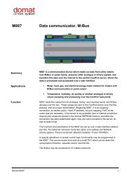
<strong>M090</strong><br />
<strong>Modbus</strong> <strong>TCP</strong> / <strong>DALI</strong> <strong>converter</strong><br />
Summary<br />
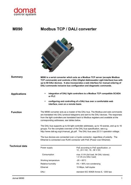
<strong>M090</strong> is a serial <strong>converter</strong> which acts as a <strong>Modbus</strong> <strong>TCP</strong> server (accepts <strong>Modbus</strong><br />
<strong>TCP</strong> commands) and controls a <strong>DALI</strong> (Digital Addressable Light Interface) bus with<br />
up to 60 <strong>DALI</strong> devices. It also incorporates a web interface for manual entering of<br />
<strong>DALI</strong> commands inclusive bus configuration and diagnostic commands.<br />
Applications<br />
<br />
<br />
integration of <strong>DALI</strong> light controllers to a <strong>Modbus</strong> <strong>TCP</strong> compatible SCADA<br />
or PLC<br />
configuring and controlling of a <strong>DALI</strong> bus over a comfortable web<br />
interface, even on a remote basis<br />
Function<br />
The <strong>M090</strong> <strong>converter</strong> acts as a master of the <strong>DALI</strong> bus. The <strong>Modbus</strong> and web commands<br />
are translated into <strong>DALI</strong> protocol telegrams and sent to the <strong>DALI</strong> devices. The responses<br />
from the light controllers are translated back to <strong>Modbus</strong> registers and available at the<br />
corresponding addresses, see tables below.<br />
The <strong>DALI</strong> bus supports up to 64 light controller addresses, up to 16 scenes, and up to 16<br />
groups. For the complete overview of the <strong>DALI</strong> bus specification, see e.g.<br />
http://www.dali-ag.org/c/manual_gb.pdf . The <strong>DALI</strong> bus uses 22.5 V operation voltage.<br />
The bus devices are connected over a 2-pole connector, regardless of polarity. The<br />
Ethernet is connected over RJ45 connector with PoE (Power over Ethernet).<br />
Technical data<br />
Power supply<br />
PoE according to PoE specification, or<br />
12...24 V AC, 16...36 V DC<br />
Consumption<br />
Working temperature -20 ÷ 65°C<br />
Relative humidity<br />
Ethernet<br />
max. 6 VA (full load, 64 <strong>DALI</strong> slaves)<br />
1.4 VA (no <strong>DALI</strong> load)<br />
5% ÷ 95% non-condensing<br />
10 Mbps, half-duplex<br />
<strong>DALI</strong><br />
standard IEC 60929 Annex E, 1200 bps<br />
domat <strong>M090</strong> 1
Galvanic separation<br />
Short circuit protection<br />
Overload sustainability<br />
LED<br />
Dimensions<br />
<strong>DALI</strong> bus is separated up to 1000 V<br />
electronic with automatic reset,<br />
short-circuit current I k = 250 mA<br />
Sustainable to unlimited bus short-circuit<br />
power (PWR) – green<br />
<strong>DALI</strong> bus receive RxD – green<br />
<strong>DALI</strong> bus transmit TxD (flashing) or overload /<br />
short-circuit (steadily on) - red<br />
see below<br />
The <strong>converter</strong> may be adjusted so as to provide maximum output current of 300 mA<br />
instead of 250 mA required by the <strong>DALI</strong> standard. This adaptation may help if the <strong>DALI</strong><br />
bus is of extreme length. Please specify <strong>M090</strong>/300mA when ordering. The readjusted<br />
<strong>converter</strong> is not suitable for standard installations! Please consult its application with a<br />
Domat Control System representative.<br />
Power supply<br />
Alternative power supply (G/G0 terminals vs. PoE):<br />
1. If the G/G0 power is applied first, the <strong>M090</strong> is powered from this G/G0 external<br />
source. At power dropout the power is switched over to PoE with a short dropout<br />
(device reset).<br />
2. If the PoE power is applied first, the <strong>M090</strong> is powered from the PoE. The switchover<br />
to G/G0 follows only if the G/G0 voltage is 27 V DC (19 V AC) and above.<br />
3. If both G/G0 and PoE are applied at the same time, the <strong>M090</strong> is powered from<br />
G/GO terminals. The device will not be damaged.<br />
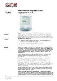
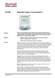
Terminals, LED<br />
1 2 ET HERNET PoE<br />
G, G0 power, any polarity<br />
ETH<br />
Ethernet, 8 pin RJ45 socket<br />
<strong>DALI</strong> + <strong>DALI</strong> bus, positive<br />
<strong>DALI</strong> - <strong>DALI</strong> bus, negative<br />
<strong>M090</strong><br />
TXD / ALR<br />
RXD<br />
PWR<br />
data transmit to <strong>DALI</strong> bus, (flashing)<br />
/ <strong>DALI</strong> bus overload (steadily on), red LED<br />
data receive from <strong>DALI</strong> bus, green LED<br />
power OK, green LED<br />
DA L I- DAL I+ INIT<br />
R XD<br />
TXD<br />
PW R<br />
INIT<br />
INIT switch (DIP switch 1) – when set on<br />
power on, the IP address is set to defaults<br />
(192.168.1.99, mask 255.255.255.0)<br />
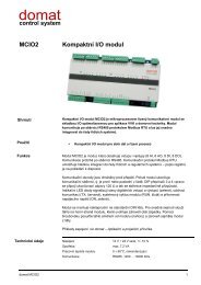
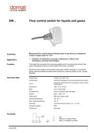
Dimensions<br />
45<br />
8,5<br />
8,5<br />
14<br />
14<br />
90<br />
36<br />
21,5<br />
53<br />
58<br />
10<br />
domat <strong>M090</strong> 2
Settings<br />
The network properties are set over the <strong>M090</strong>’s web interface. The default network<br />
settings are:<br />
IP address 192.168.1.99<br />
Network mask 255.255.255.0<br />
Default gateway 192.168.1.1<br />
All settings are stored in EEPROM.<br />
Bringing the device to default settings:<br />
1. Power off the <strong>M090</strong>.<br />
2. Set the DIP switch 1 (INIT) to ON.<br />
3. Apply power.<br />
4. Locate the device on its default IP address and configure it as necessary.<br />
5. Remove power.<br />
6. Set the INIT switch to OFF.<br />
7. Apply power again.<br />
8. The <strong>M090</strong> has the new settings.<br />
Web interface<br />
Over the web interface it is possible to set the <strong>M090</strong> up (Network config), upload new<br />
firmware if necessary (Administration), and diagnose the interface (Statistics). The <strong>DALI</strong><br />
Control menu is used to test if the <strong>DALI</strong> part is operating properly, to address the ballasts<br />
(Addressing), set the individual ballast parameters (ECG settings), see the states of the<br />
lamps at a glance (Lamp status), configure scenes and groups, and issue group<br />
commands (Ligthing).<br />
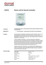
Lamp Status menu<br />
domat <strong>M090</strong> 3
ECG Settings menu<br />
The web interface is useful when commissioning the system: the <strong>DALI</strong> bus may be<br />
checked separately from the PLC program. As soon as the groups are configured and it<br />
is possible to control the <strong>DALI</strong> ballasts over the web interface, it is time to commission the<br />
PLC part.<br />
In the SoftPLC, there is a special driver for <strong>M090</strong> so that the integration is easy – it is not<br />
necessary to map the <strong>Modbus</strong> registers via a generic <strong>Modbus</strong> driver, there are dedicated<br />
variables to control central commands, groups, scenes, as well as individual ballasts.<br />
Related products<br />
IPLC510<br />
IPCT.1<br />
IPCB.1<br />
RC-Vision<br />
process station MiniPLC - Linux<br />
process station with touch screen display<br />
process station without display<br />
SCADA software<br />
<strong>Modbus</strong> <strong>TCP</strong><br />
communication<br />
The address space is accessible wordwise (16 bit words). See table below.<br />
domat <strong>M090</strong> 4
Tab. 1: <strong>Modbus</strong> table<br />
The supported <strong>Modbus</strong> functions are:<br />
01 Read Coil Status – read bits<br />
03 Read Holding Registers – read words<br />
15 Force Multiple Coils – write bits<br />
16 Force Multiple Registers – write words<br />
Name Address Type Description Note<br />
modul LSB 1 LSB R module ID lower byte 0x0090 hex<br />
modul MSB 1 MSB R module ID upper byte<br />
firmware LSB 2 LSB R firmware version lower byte<br />
firmware MSB 2 MSB R firmware version upper byte<br />
3 LSB R reserved<br />
status MSB 3 MSB R module status upper byte<br />
bit 0 - 0 normal mode<br />
- 1 init mode<br />
bit 1 - 0<br />
bit 2 - 0<br />
bit 3 - 0<br />
bit 4 - 0<br />
bit 5 - 1<br />
bit 6 - 0<br />
bit 7 - 1<br />
reserved 4 LSB R RAM<br />
reserved 4 MSB R RAM<br />
command mask 5 LSB R,W RAM bit 0 = block 0<br />
bit 1 = block 1<br />
bit 2 = block 2<br />
bit 3 = block 3<br />
bit 4 = block 4<br />
bit 5 = block 5<br />
bit 6 = block 6<br />
bit 7 = block 7<br />
command<br />
executed<br />
<strong>DALI</strong> command<br />
block 0<br />
<strong>DALI</strong> address<br />
block 0<br />
By setting the bit, executing<br />
of the corresponding block is<br />
enabled. The module<br />
executes the enabled blocks<br />
one after another from bit 7<br />
to bit 0<br />
5 MSB R RAM The set bit indicates the<br />
executed block, bit 0 = block<br />
0 etc.<br />
6 LSB R,W RAM <strong>DALI</strong> command for block 0<br />
according to the tables<br />
6 MSB R,W RAM <strong>DALI</strong> address for block 0<br />
D0 block 0 7 LSB R,W RAM if the request is performed by a single<br />
<strong>DALI</strong> command which contains<br />
answer, the answer is in this block<br />
additional data 0 for block 0<br />
-> tables<br />
domat <strong>M090</strong> 5
D1 block 0 7 MSB R,W RAM If the request is performed by a single<br />
<strong>DALI</strong> command, then:<br />
0x00 – no reply returned<br />
0x55 – valid <strong>DALI</strong> reply returned, and<br />
stored in register 7LSB<br />
0x02 – bus error, bus permanently<br />
short-circuited<br />
0x03 – <strong>DALI</strong> reply returned but<br />
damaged (unrecognized)<br />
additional data 1 for block 0<br />
-> tables<br />
D2 block 0 8 LSB R,W RAM additional data 2 for block 0<br />
-> tables<br />
8 MSB reserved<br />
<strong>DALI</strong> command 9 LSB R,W RAM<br />
block 1<br />
<strong>DALI</strong> address 9 MSB R,W RAM<br />
block 1<br />
D0 block 1 10 LSB R,W RAM<br />
D1 block 1 10 MSB R,W RAM<br />
D2 block 1 11 LSB R,W RAM<br />
11 MSB reserved<br />
<strong>DALI</strong> command 12 LSB R,W RAM<br />
block 2<br />
<strong>DALI</strong> address 12 MSB R,W RAM<br />
block 2<br />
D0 block 2 13 LSB R,W RAM<br />
D1 block 2 13 MSB R,W RAM<br />
D2 block 2 14 LSB R,W RAM<br />
14 MSB reserved<br />
<strong>DALI</strong> command 15 LSB R,W RAM<br />
block 3<br />
<strong>DALI</strong> address 15 MSB R,W RAM<br />
block 3<br />
D0 block 3 16 LSB R,W RAM<br />
D1 block 3 16 MSB R,W RAM<br />
D2 block 3 17 LSB R,W RAM<br />
17 MSB<br />
<strong>DALI</strong> command 18 LSB R,W RAM<br />
block 4<br />
<strong>DALI</strong> address 18 MSB R,W RAM<br />
block 4<br />
D0 block 4 19 LSB R,W RAM<br />
D1 block 4 19 MSB R,W RAM<br />
D2 block 4 20 LSB R,W RAM<br />
20 MSB reserved<br />
<strong>DALI</strong> command 21 LSB R,W RAM<br />
block 5<br />
<strong>DALI</strong> address 21 MSB R,W RAM<br />
block 5<br />
D0 block 5 22 LSB R,W RAM<br />
D1 block 5 22 MSB R,W RAM<br />
D2 block 5 23 LSB R,W RAM<br />
23 MSB reserved<br />
<strong>DALI</strong> command 24 LSB R,W RAM<br />
block 6<br />
<strong>DALI</strong> address<br />
block 6<br />
24 MSB R,W RAM<br />
domat <strong>M090</strong> 6
D0 block 6 25 LSB R,W RAM<br />
D1 block 6 25 MSB R,W RAM<br />
D2 block 6 26 LSB R,W RAM<br />
26 MSB reserved<br />
<strong>DALI</strong> command 27 LSB R,W RAM<br />
block 7<br />
<strong>DALI</strong> address 27 MSB R,W RAM<br />
block 7<br />
D0 block 7 28 LSB R,W RAM<br />
D1 block 7 28 MSB R,W RAM<br />
D2 block 7 29 LSB R,W RAM<br />
29 MSB reserved<br />
Tab. 2: Standard <strong>DALI</strong> commands<br />
No. <strong>DALI</strong> command <strong>DALI</strong> address D0 D1 D2 Function<br />
(bin)<br />
0 0000 0000 YAAA AAA 1 0 0 0 Extinguish the lamp without fading (Off)<br />
1 0000 0001 YAAA AAA 1 0 0 0 Set to MAX LEVEL using FADE RATE<br />
2 0000 0010 YAAA AAA 1 0 0 0 Set to MIN LEVEL using FADE RATE<br />
3 0000 0011 YAAA AAA 1 0 0 0 One step higher without fading<br />
4 0000 0100 YAAA AAA 1 0 0 0 One step lower without fading<br />
5 0000 0101 YAAA AAA 1 0 0 0 Set to MAX LEVEL (On)<br />
6 0000 0110 YAAA AAA 1 0 0 0 Set to MIN LEVEL (Dim)<br />
7 0000 0111 YAAA AAA 1 0 0 0 One step lower, if the light is at MIN LEVEL it<br />
goes to Off<br />
8 0000 1000 YAAA AAA 1 0 0 0 One step higher, if the light is Off it goes to<br />
MIN LEVEL<br />
.9-15 0000 1XXX Not used<br />
16-31 0001 XXXX YAAA AAA 1 0 0 0 Set the light value to the scene XXXX<br />
32 0010 0000 YAAA AAA 1 0 0 0 Reset the ballast to default settings<br />
33 0010 0001 YAAA AAA 1 0 0 0 Save actual value to DTR<br />
34-41 0010 XXXX Not used<br />
42 0010 1010 YAAA AAA 1 0 0 0 Save DTR as MAX LEVEL<br />
43 0010 1011 YAAA AAA 1 0 0 0 Save DTR as MIN LEVEL<br />
44 0010 1100 YAAA AAA 1 0 0 0 Save DTR as SYSTEM FAILURE LEVEL<br />
45 0010 1101 YAAA AAA 1 0 0 0 Save DTR as POWER ON LEVEL<br />
46 0010 1110 YAAA AAA 1 0 0 0 Save DTR as FADE TIME<br />
47 0010 1111 YAAA AAA 1 0 0 0 Save DTR as FADE RATE<br />
48-63 0011 XXXX Not used<br />
64-79 0100 XXXX YAAA AAA 1 0 0 0 Save DTR as new value for scene 0-15<br />
80-95 0101 XXXX YAAA AAA 1 0 0 0 Remove ballast from scene 0-15,<br />
i.e. set 0xFF to the Scene register XXXX<br />
96-111 0110 XXXX YAAA AAA 1 0 0 0 Add ballast to group 0-15<br />
112-127 0111 XXXX YAAA AAA 1 0 0 0 Remove ballast from group 0-15<br />
128 1000 0000 YAAA AAA 1 0 0 0 Save DTR as short address<br />
129-143 1000 XXXX Not used<br />
144 1001 0000 YAAA AAA 1 0 0 0 Ballast status request<br />
bit 0 – Ballast status; 0 = OK<br />
bit 1 – Lamp failure; 0 = OK<br />
bit 2 – Power on; 0 = OK<br />
bit 4 – Fading up/down; 0 = not active 1 =<br />
active<br />
bit 5 – Ballast in reset mode; 0 = is not 1 = is<br />
in reset mode<br />
bit 6 – Short ballast address missing; 0 = not<br />
missing<br />
bit 7 – POWER FAILURE; 0 = no Power<br />
Failure<br />
145 1001 0001 YAAA AAA 1 0 0 0 Ballast request; if ballast with this address is<br />
connected and communicative, it responds<br />
YES otherwise NO<br />
domat <strong>M090</strong> 7
146 1001 0010 YAAA AAA 1 0 0 0 Request if there is a problem with the lamp<br />
147 1001 0011 YAAA AAA 1 0 0 0 Request if the lamp connected to the ballast<br />
is working properly<br />
148 1001 0100 YAAA AAA 1 0 0 0 Request if the last command for writing<br />
actual level has been performed<br />
149 1001 0101 YAAA AAA 1 0 0 0 Request if ballast is in Reset mode<br />
150 1001 0110 YAAA AAA 1 0 0 0 Request if ballast is without short address<br />
151 1001 0111 YAAA AAA 1 0 0 0 Returns ballast version according to IEC<br />
standard<br />
152 1001 1000 YAAA AAA 1 0 0 0 Returns actual DTR value<br />
153 1001 1001 YAAA AAA 1 0 0 0 Returns device type, standard is 0<br />
154 1001 1010 YAAA AAA 1 0 0 0 Returns „PHYSICAL MINIMUM LEVEL“ value<br />
155 1001 1011 YAAA AAA 1 0 0 0 Returns the POWER FAILURE value<br />
156-159 1001 11XX Not used<br />
160 1010 0000 YAAA AAA 1 0 0 0 Returns the current light level<br />
161 1010 0001 YAAA AAA 1 0 0 0 Returns the MAX LEVEL value<br />
162 1010 0010 YAAA AAA 1 0 0 0 Returns the MIN LEVEL value<br />
163 1010 0011 YAAA AAA 1 0 0 0 Returns the POWER ON LEVEL value<br />
164 1010 0100 YAAA AAA 1 0 0 0 Returns the SYSTEM FAILURE LEVEL value<br />
165 1010 0101 YAAA AAA 1 0 0 0 Returns the FADE TIME/FADE RATE value<br />
Answer XXXXYYYY means: XXXX = FADE<br />
TIME, and YYYY = FADE RATE<br />
166-175 1010 XXXX Not used<br />
176-191 1011 XXXX YAAA AAA 1 0 0 0 Returns the light level for the selected scene<br />
0-15<br />
0000 – scene 0<br />
192 1100 0000 YAAA AAA 1 0 0 0 Returns the bit pattern indicating which<br />
groups the slave belongs to (0-7)<br />
bit 0 = group 0 etc.<br />
value 0 = ballast is not member of the group<br />
value 1 = ballast is member of the group<br />
193 1100 0001 YAAA AAA 1 0 0 0 Returns the bit pattern indicating which<br />
groups the slave belongs to (8-15), see above<br />
194 1100 0010 YAAA AAA 1 0 0 0 Returns the high bits of the random address<br />
H<br />
195 1100 0011 YAAA AAA 1 0 0 0 Returns the middle bits of the random<br />
address M<br />
196 1100 0100 YAAA AAA 1 0 0 0 Returns the low bits of the random address L<br />
197-223 110X XXXX Not used<br />
224-255 11XX XXXX YAAA AAA 1 0 0 0 Extended requests, free to interpret<br />
257 1010 0011 XXXX XXXX 0 0 0 Store value XXXX XXXX to DTR<br />
Tab. 3: Address types<br />
Short address 0-63 0AAAAAA1<br />
Group address 0-15 100AAAA1<br />
Broadcast 11111111<br />
Direct control 0-63 0AAAAAA0<br />
Tab. 4: Extended commands<br />
No. <strong>DALI</strong> <strong>DALI</strong> address D0 D1 D2 Function<br />
command<br />
(dec)<br />
258 258 YAAA AAA1 0100 XXXX Value 0x01 Store value as new parameter of<br />
259 259 1AAA AAA1 0110 XXXX<br />
0111 XXXX<br />
scene XXXX<br />
- 0x02 0110 XXXX = Add ballast to<br />
group XXXX<br />
0111 XXXX = Remove ballast<br />
from group XXXX<br />
260 260 YAAA AAA1 - Value 0x03 Store value as „FADE TIME“<br />
261 261 YAAA AAA1 - Value 0x04 Store value as „FADE RATE“<br />
262 262 YAAA AAA1 - Value 0x05 Store value as „MAX LEVEL“<br />
domat <strong>M090</strong> 8
263 263 YAAA AAA1 - Value 0x06 Store value as „MIN LEVEL“<br />
264 264 YAAA AAA1 - Value 0x07 Store value as „SYSTEM<br />
FAILURE LEVEL“<br />
265 265 YAAA AAA1 - Value 0x08 Store value as „POWER ON<br />
LEVEL“<br />
266 266 0x09 Completely new addressing<br />
267 267 Address to start 0AAA AAA1 0x0A New addressing of all ballasts<br />
with<br />
with given address<br />
268 268 Address to start<br />
with<br />
0x0B New addressing of ballasts<br />
without short address<br />
269 269 0AAA AAA1 - - 0x0C Deletes given short address of<br />
ballast<br />
270 270 YAAA AAA1 - YAAA AAA1 0x0D Changes current address to new<br />
(current address)<br />
(new address) address<br />
271 271 YAAA AAA1 number of<br />
winks [1-255]<br />
wink time in<br />
secs [1-255]<br />
0x0E winks the addressed ballast;<br />
wink values must not be 0!<br />
272 272 0x0F Short addresses request [0-31]<br />
273 273 0x10 Short addresses request [32-63]<br />
274 274 0x11 Ballast status request [0-31]<br />
275 275 0x12 Ballast status request [32-63]<br />
276 276 0x13 “Lamp failure“ request [0-31]<br />
277 277 0x14 “Lamp failure“ request [32-63]<br />
278 278 0x15 “Lamp power on“ request [0-31]<br />
279 279 0x16 “Lamp power on“ request [32-<br />
63]<br />
Tab. 5: Answers for extended commands<br />
No. <strong>DALI</strong> command <strong>DALI</strong> address D0 D1 D2 Function<br />
258 - - - -<br />
259 - - - - -<br />
260 - - - - -<br />
261 - - - - -<br />
262 - - - - -<br />
263 - - - - -<br />
264 - - - - -<br />
265 - - - - -<br />
266 - - Number of<br />
addressed<br />
ballasts [0-63]<br />
267 - - Number of<br />
addressed<br />
ballasts [0-63]<br />
268 - - Number of<br />
addressed<br />
- - Completely new<br />
addressing<br />
- - New addressing of all<br />
ballasts with given<br />
address<br />
- - New addressing of all<br />
ballasts without short<br />
address<br />
ballasts [0-63]<br />
269 - - - - -<br />
270 - - - - -<br />
271 - - - - -<br />
272 Addresses 8-15 Addresses 0-7 Addresses 23-31 Addresses 16-22 - 1 – Yes<br />
0 - No<br />
273 Addresses 40-47 Addresses 32-39 Addresses 56-63 Addresses 48-55 - 1 – Yes<br />
0 - No<br />
274 Addresses 8-15 Addresses 0-7 Addresses 23-31 Addresses 16-22 - 1 - Error<br />
0 - OK<br />
275 Addresses 40-47 Addresses 32-39 Addresses 56-63 Addresses 48-55 - 1 - Error<br />
0 - OK<br />
276 Addresses 8-15 Addresses 0-7 Addresses 23-31 Addresses 16-22 - 1 - Error<br />
0 - OK<br />
277 Addresses 40-47 Addresses 32-39 Addresses 56-63 Addresses 48-55 - 1 - Error<br />
0 - OK<br />
278 Addresses 8-15 Addresses 0-7 Addresses 23-31 Addresses 16-22 - 1 - On<br />
0 - Off<br />
279 Addresses 40-47 Addresses 32-39 Addresses 56-63 Addresses 48-55 - 1 - On<br />
0 - Off<br />
domat <strong>M090</strong> 9
Light level control<br />
It is possible to control the light level using two different ways. <strong>DALI</strong> recognizes direct and<br />
indirect light level control.<br />
Indirect light level control<br />
The command consists of 2 bytes.<br />
Byte 1 <strong>DALI</strong> address (short address / group address / broadcast)<br />
Byte 2 Standard or Extended <strong>DALI</strong> command – see tables above.<br />
Direct light level control<br />
The command consists of 2 bytes.<br />
Byte 1 <strong>DALI</strong> address; this is the <strong>DALI</strong> ballast short address, with the first bit of 0.<br />
Byte 2 Light level: a number in the range of 0...255 which specifies a value within MIN<br />
LEVEL and MAX LEVEL interval. Example: MIN = 100, MAX = 200: to set the light to 50<br />
%, a value of 150 must be sent.<br />
This is a way how to control the light level directly without using of groups, scenes etc.<br />
Example of a<br />
<strong>Modbus</strong> <strong>TCP</strong><br />
command<br />
There are 8 "blocks" - (0 to 7) – which represent positions for the <strong>DALI</strong> commands.<br />
To execute a command,<br />
- the block(s) must be filled with the data representing the command(s)<br />
- bit(s) in Register 5 LSB which corresponds to the block to be executed must be<br />
set.<br />
After executing of the command, the info bit in register 5 MSB is set so that the<br />
<strong>Modbus</strong> master can read that the execution was OK.<br />
If a command is generating a response, the response is stored in the D0..D2<br />
registers of the particular block.<br />
More blocks may be filled at the same time and executed all together by writing a<br />
corresponding bit pattern into register 5 LSB.<br />
Example:<br />
Tx: 00 07 00 00 00 0D 01 10 00 05 00 03 06 0B 05 00 00 00 00<br />
A <strong>Modbus</strong> <strong>TCP</strong> example telegram for ballast Adr 6: set to max (<strong>DALI</strong> function<br />
5). It is written in command block 0 (<strong>Modbus</strong> register 6, which is <strong>Modbus</strong> address<br />
5).<br />
00 07 00 00 00 0D 01 Details see <strong>Modbus</strong> <strong>TCP</strong> frame structure<br />
10 <strong>Modbus</strong> F16, write multiple registers<br />
00 05 <strong>Modbus</strong> address to be written to, address 5 = register 6<br />
00 03 Number of 16bit registers to be written<br />
06 Number of bytes to follow<br />
0B 05 00 00 00 00 The data is 0B 05 for command block 0, other command<br />
blocks 1 and 2 are empty (00 00 00 00) - (this is how the client software, with which<br />
the example was done, is communicating: it writes three blocks at a time; other<br />
clients may only send the first couple of bytes).<br />
The most important data is 0B 05.<br />
05: LSB = <strong>DALI</strong> command, see Tab 2 No.5<br />
0B: MSB = 0000 1011 - the structure of a standard <strong>DALI</strong> command - see Tab 2:<br />
Y AAA AAA 1, where<br />
domat <strong>M090</strong> 10
Y = 0 for Short address (see Tab 3), and<br />
AAA AAA = 000 101 = 5 = <strong>DALI</strong> address of the ballast.<br />
In a similar way more command blocks may be filled, and then activated at the same<br />
time.<br />
Another <strong>Modbus</strong> <strong>TCP</strong> telegram has to activate (execute) this command:<br />
Address 6: execute block 0 (write 1 into <strong>Modbus</strong> register 5, or <strong>Modbus</strong> address 4)<br />
00 08 00 00 00 09 01 Details see <strong>Modbus</strong> <strong>TCP</strong> frame structure<br />
10 <strong>Modbus</strong> F16, write multiple registers<br />
00 04 <strong>Modbus</strong> address to be written to, address 4 = register 5<br />
00 01 Number of 16bit registers to be written<br />
02 Number of bytes to follow<br />
00 01 1 at Bit 0 means Execute command block 1. At this time<br />
the commands from Block D0 are sent to the <strong>DALI</strong> bus.<br />
10/2012 Subject to technical changes.<br />
domat <strong>M090</strong> 11