Canister Design 2012 (pdf) (7.2 MB) - Posiva
Canister Design 2012 (pdf) (7.2 MB) - Posiva
Canister Design 2012 (pdf) (7.2 MB) - Posiva

You also want an ePaper? Increase the reach of your titles
YUMPU automatically turns print PDFs into web optimized ePapers that Google loves.
POSIVA <strong>2012</strong>-13<br />
<strong>Canister</strong> <strong>Design</strong> <strong>2012</strong><br />
Heikki Raiko<br />
VTT<br />
April 2013<br />
POSIVA OY<br />
Olkiluoto<br />
FI-27160 EURAJOKI, FINLAND<br />
Phone (02) 8372 31 (nat.), (+358-2-) 8372 31 (int.)<br />
Fax (02) 8372 3809 (nat.), (+358-2-) 8372 3809 (int.)
ISBN 978-951-652-194-0<br />
ISSN 1239-3096
<strong>Posiva</strong>-raportti – <strong>Posiva</strong> Report<br />
<strong>Posiva</strong> Oy<br />
Olkiluoto<br />
FI-27160 EURAJOKI, FINLAND<br />
Puh. 02-8372 (31) – Int. Tel. +358 2 8372 (31)<br />
Raportin tunnus – Report code<br />
POSIVA <strong>2012</strong>-13<br />
Julkaisuaika – Date<br />
December <strong>2012</strong><br />
Tekijä(t) – Author(s)<br />
Heikki Raiko, VTT<br />
Toimeksiantaja(t) – Commissioned by<br />
<strong>Posiva</strong> Oy<br />
Nimeke – Title<br />
CANISTER DESIGN <strong>2012</strong><br />
Tiivistelmä – Abstract<br />
This report summarises the design of the <strong>Posiva</strong> disposal canister for spent nuclear fuel. The report<br />
presents the design bases, the reference design, and summarises the performance analyses carried<br />
out for the design. The report mainly addresses the long-term properties of the canister, but<br />
operational safety aspects are also included because they may affect long-term safety.<br />
Report presents the detailed design of the reference canister (for BWR fuel) and in more general<br />
terms the variant designs for the other nuclear fuel types (VVER and EPR/PWR). The design<br />
report also describes the main features of the canister manufacture, encapsulation and handling.<br />
This report addresses aspects concerning the manufacture, quality control, mechanical strength,<br />
chemical resistance, nuclear engineering analyses, thermal dimensioning, canister handling and<br />
material ageing phenomena. Interaction of canister and other engineered barriers are included in<br />
the study. The evolution of repository and its main drivers are considered if they have an impact on<br />
the canister performance.<br />
This report fulfils the requirements of the preliminary safety analysis-report (PSAR) concerning<br />
the description of the disposal canister and of its performance qualification in the expected<br />
repository conditions during its long-term evolution.<br />
Avainsanat - Keywords<br />
Final disposal canister, canister design, performance assessment, spent fuel.<br />
ISBN<br />
ISBN 978-951-652-194-0<br />
Sivumäärä – Number of pages<br />
156<br />
ISSN<br />
Kieli – Language<br />
ISSN 1239-3096<br />
English
<strong>Posiva</strong>-raportti – <strong>Posiva</strong> Report<br />
<strong>Posiva</strong> Oy<br />
Olkiluoto<br />
FI-27160 EURAJOKI, FINLAND<br />
Puh. 02-8372 (31) – Int. Tel. +358 2 8372 (31)<br />
Raportin tunnus – Report code<br />
POSIVA <strong>2012</strong>-13<br />
Julkaisuaika – Date<br />
Joulukuu <strong>2012</strong><br />
Tekijä(t) – Author(s)<br />
Heikki Raiko, VTT<br />
Toimeksiantaja(t) – Commissioned by<br />
<strong>Posiva</strong> Oy<br />
Nimeke – Title<br />
KAPSELISUUNNITELMA <strong>2012</strong><br />
Tiivistelmä – Abstract<br />
Tämä raportti kokoaa yhteen <strong>Posiva</strong>n käytetyn ydinpolttoaineen loppusijoituskapselin suunnittelun.<br />
Raportti esittää suunnitteluperusteet ja referenssiratkaisun sekä vetää yhteen tulokset<br />
suunnitelman toimintakykyanalyysien tuloksista. Raportti käsittelee pääasiassa kapselin pitkäaikaisturvallisuuteen<br />
liittyviä kysymyksiä, mutta myös käytönaikaiseen turvallisuuteen liittyvät<br />
kysymykset on käsitelty, koska osalla niistä voi olla vuorovaikutusta pitkäaikaisturvallisuuteen.<br />
Raportti esittelee yksityiskohtaisesti referenssikapselin suunnitelman sekä yleisemmin sen<br />
variaationa olevat muiden ydinpolttoainetyyppien kapselit. Varsinaiset toimintakykyanalyysit on<br />
raportoitu pääreferensseinä esitellyissä raporteissa. Suunnitelmassa on käsitelty myös kapselin<br />
valmistuksen, kapseloinnin ja kapselin käsittelyn pääpiirteet.<br />
Tarkastelujen aihepiirit kattavat kapselin valmistuksen, laadunvalvonnan, mekaanisen lujuuden,<br />
kemiallisen kestävyyden, ydinteknisen suunnittelun, lämpöteknisen mitoituksen, kapselin<br />
käsittelyn sekä materiaalien ikääntymisilmiöt. Kapselin ja muiden päästöesteiden vuorovaikutus<br />
on myös tarkasteluissa mukana. Loppusijoitustilan evoluutiota ja siellä vaikuttavia prosesseja<br />
tarkastellaan niiltä osin kuin ne vaikuttavat kapselin toimintakykyyn.<br />
Raportti sisältää alustavan turvallisuusselosteen (PSAR) tasoisen kuvauksen loppusijoituskapselista<br />
ja sen vaatimuksenmukaisesta toimintakyvystä loppusijoitusolosuhteissa hyvin pitkällä<br />
aikavälillä.<br />
Avainsanat - Keywords<br />
Loppusijoituskapseli, kapselin suunnitelma, polttoaine, toimintakykyarvio.<br />
ISBN<br />
ISBN 978-951-652-194-0<br />
Sivumäärä – Number of pages<br />
156<br />
ISSN<br />
Kieli – Language<br />
ISSN 1239-3096<br />
Englanti
1<br />
TABLE OF CONTENTS<br />
ABSTRACT<br />
TIIVISTELMÄ<br />
DEFINITIONS AND ABBREVIATIONS .......................................................................... 5<br />
FOREWORD .................................................................................................................. 7<br />
1 INTRODUCTION ................................................................................................... 9<br />
2 CANISTER’S FUNCTION AS A PART OF ENGINEERED BARRIER SYSTEM<br />
OF THE KBS-3 CONCEPT ................................................................................. 13<br />
2.1 Safety functions .............................................................................................. 13<br />
2.2 Performance targets ....................................................................................... 14<br />
2.3 Safety functions, performance targets and safety-related guidance to design ...<br />
................................................................................................................. 15<br />
3 DESIGN BASES FOR CANISTER ...................................................................... 19<br />
3.1 Sub-system requirements – <strong>Canister</strong> ............................................................. 20<br />
3.2 <strong>Design</strong> requirements – <strong>Canister</strong> ..................................................................... 21<br />
3.2.1 <strong>Canister</strong> performance .............................................................................. 21<br />
3.2.2 Copper overpack requirements ............................................................... 22<br />
3.2.3 Cast iron insert requirements .................................................................. 22<br />
4 DESIGN LOADS ................................................................................................. 25<br />
4.1 Handling loads ................................................................................................ 25<br />
4.2 Incidents and accidents during encapsulation, transfer and disposal ............ 25<br />
4.3 Internal loads .................................................................................................. 26<br />
4.4 External mechanical loads ............................................................................. 28<br />
4.5 External chemical loads ................................................................................. 31<br />
4.6 Mechanical load combination ......................................................................... 31<br />
5 NUCLEAR SAFETY CLASSIFICATION OF THE CANISTER ............................ 35<br />
6 CANISTER SHAPE, DIMENSIONS AND SURFACE QUALITY ......................... 37<br />
7 MECHANICAL AND PHYSICAL PROPERTIES OF THE<br />
CANISTERCOMPONENT MATERIALS.............................................................. 49<br />
7.1 Material qualities involved .............................................................................. 49<br />
<strong>7.2</strong> Mechanical properties .................................................................................... 50<br />
7.3 Models for stress strain curves ....................................................................... 55<br />
7.3.1 Models for stress strain curves for iron and steels .................................. 55<br />
7.3.2 Model for stress strain curves of copper ................................................. 55<br />
7.3.3 Copper creep model ................................................................................ 56<br />
7.3.4 The copper creep model for multiaxial stress states ............................... 58<br />
7.3.5 Comparison to copper creep tests for notched specimens ..................... 59
2<br />
7.3.6 <strong>Posiva</strong>’s copper creep testing and canister evaluation ........................... 59<br />
7.4 Bentonite material model ................................................................................ 63<br />
7.5 Physical properties of canister materials ........................................................ 65<br />
8 VERIFICATION OF CANISTER DIMENSIONING .............................................. 67<br />
8.1 Mechanical failure processes ......................................................................... 67<br />
8.1.1 Copper overpack ..................................................................................... 67<br />
8.1.2 Insert ....................................................................................................... 67<br />
8.2 Mechanical failure criteria ............................................................................... 68<br />
8.2.1 Copper overpack ..................................................................................... 68<br />
8.2.2 Insert ....................................................................................................... 69<br />
8.2.3 Summary of mechanical failure criteria relevance .................................. 74<br />
8.3 Strength and damage tolerance ..................................................................... 74<br />
8.3.1 Plastic collapse criteria ............................................................................ 75<br />
8.3.2 Stress / strain criteria .............................................................................. 76<br />
8.3.3 Fracture resistance criteria / allowable defect sizes ................................ 81<br />
8.3.4 Essential design parameters ................................................................... 81<br />
8.3.5 Strength of variant canister designs ........................................................ 83<br />
8.4 Thermal behaviour ......................................................................................... 85<br />
8.4.1 Temperature inside canister .................................................................... 85<br />
8.4.2 Thermal expansion of canister components ........................................... 86<br />
8.4.3 Thermal evolution of the canister surface ............................................... 89<br />
8.4.4 <strong>Canister</strong> during permafrost ...................................................................... 91<br />
8.4.5 Thermal behaviour of the variant canister designs ................................. 92<br />
8.5 Cooling of the canister in all expected conditions .......................................... 92<br />
8.5.1 <strong>Canister</strong> in encapsulation plant ............................................................... 92<br />
8.5.2 <strong>Canister</strong> in transfer vehicle ...................................................................... 95<br />
8.5.3 Fire .......................................................................................................... 96<br />
8.5.4 <strong>Canister</strong> in repository .............................................................................. 97<br />
8.5.5 Cooling capacity of variant canister designs ........................................... 99<br />
8.6 Corrosion resistance ...................................................................................... 99<br />
8.6.1 Atmospheric corrosion in the encapsulation plant ................................... 99<br />
8.6.2 Corrosion during repository operation ................................................... 100<br />
8.6.3 Corrosion in the repository under unsaturated, oxic conditions ............ 100<br />
8.6.4 Corrosion in the repository under saturated as well as anoxic and<br />
reducing conditions ............................................................................... 102<br />
8.6.5 Stress corrosion cracking ...................................................................... 104<br />
8.6.6 Corrosion inside the canister ................................................................. 105<br />
8.6.7 Corrosion in the weld and grain boundaries .......................................... 106
3<br />
8.6.8 Conclusions about corrosion resistance ............................................... 107<br />
8.7 Radiation dose rates .................................................................................... 108<br />
8.8 Materials ageing due to radiation dose ........................................................ 111<br />
8.8.1 Conclusion about radiation induced ageing .......................................... 112<br />
8.9 Criticality safety ............................................................................................ 114<br />
9 RATIONALE FOR THE SELECTION OF MANUFACTURING MATERIALS AND<br />
THEIR SPECIFIED PROPERTIES ................................................................... 115<br />
9.1 Insert materials ............................................................................................. 115<br />
9.2 Overpack material ........................................................................................ 115<br />
10 MANUFACTURING OF THE CANISTER COMPONENTS ............................... 117<br />
10.1 Insert manufacturing ..................................................................................... 117<br />
10.2 Copper overpack manufacturing .................................................................. 117<br />
10.3 Component inspections ................................................................................ 118<br />
10.3.1 <strong>Canister</strong> insert inspections .................................................................... 118<br />
10.3.2 Copper overpack inspections ................................................................ 118<br />
11 ENCAPSULATION PROCESS.......................................................................... 121<br />
11.1 Fuel preparation ........................................................................................... 121<br />
11.2 Fuel handling and packaging into canister ................................................... 121<br />
11.3 <strong>Canister</strong> preparation before sealing ............................................................. 122<br />
11.4 Sealing weld of the copper overpack ........................................................... 122<br />
11.5 Final machining of welded surfaces ............................................................. 123<br />
11.6 Weld controls ................................................................................................ 123<br />
11.7 Final control .................................................................................................. 126<br />
12 CANISTER TRANSFER AND DEPOSITION .................................................... 127<br />
12.1 <strong>Canister</strong> handling and transfer ..................................................................... 127<br />
12.2 Control of handling and transfer damages ................................................... 128<br />
12.3 <strong>Canister</strong> deposition ....................................................................................... 128<br />
13 CANISTER INITIAL STATE .............................................................................. 129<br />
13.1 Fuel types ..................................................................................................... 129<br />
13.2 Average fuel burnup, number of fuel assemblies and activity inventory ...... 131<br />
13.3 Fillers and residual contents of canisters ..................................................... 132<br />
13.4 Decay heat ................................................................................................... 132<br />
13.5 <strong>Canister</strong> size, shape and material integrity .................................................. 133<br />
13.6 Adverse effects of manufacturing process on the materials ......................... 133<br />
13.6.1 Residual stresses in seal weld .............................................................. 133<br />
13.6.2 Residual stresses in cast iron insert ...................................................... 134<br />
13.6.3 Temper embrittlement in cast iron insert ............................................... 136
4<br />
14 ASSESSMENT OF CANISTER COMPLIANCE WITH DESIGN<br />
REQUIREMENTS ............................................................................................. 137<br />
14.1 <strong>Design</strong> analysis evidence against design requirements ............................... 137<br />
14.2 Continuing research work on performance assessment .............................. 139<br />
14.3 Uncertainty of analyses and assessments ................................................... 140<br />
15 SUMMARY ........................................................................................................ 143<br />
REFERENCES ........................................................................................................... 147
5<br />
DEFINITIONS AND ABBREVIATIONS<br />
Buffer<br />
Compacted bentonite blocks and pellets surrounding the copper canister in the deposition<br />
hole.<br />
BWR<br />
Boiling water reactor.<br />
<strong>Canister</strong><br />
Metal container used for spent nuclear fuel disposal in bedrock.<br />
<strong>Canister</strong> overpack<br />
Corrosion protection and leak-tight shell around canister insert. Made of oxygen-free<br />
copper.<br />
<strong>Canister</strong> insert<br />
Cast iron body of the disposal canister. Stands for mechanical loads, inhibits criticality,<br />
part of radiation protection shield, part of decay heat transfer chain.<br />
Deposition hole<br />
The vertical hole where the canister and the surrounding buffer are emplaced in KBS-<br />
3V concept.<br />
Deposition tunnel<br />
The tunnel, where the deposition holes are located in KBS-3V concept.<br />
EPR<br />
European pressurised water reactor.<br />
EBS<br />
Engineered Barrier System refers to the barrier system, which consists of host rock as a<br />
natural barrier, canister, clay buffer and backfill of the deposition tunnels. It includes<br />
also the backfill and plugs in other openings and the plugs of the deposition tunnels.<br />
Initial state<br />
The initial state is the state a given component has after it has been emplaced according<br />
to its design when the direct control over that specific part of the system ceases and only<br />
limited information can be made available on the subsequent development of conditions<br />
in that part of the system or its near-field.<br />
KBS<br />
(Kärnbränslesäkerhet). The method for implementing the spent nuclear fuel disposal<br />
concept based on multiple barriers.<br />
KBS-3V<br />
(Kärnbränslesäkerhet 3-Vertikal). The reference design alternative of the KBS-3<br />
method, in which the spent nuclear fuel canisters are emplaced in individual vertical<br />
deposition holes.
6<br />
LO1, LO2<br />
Loviisa nuclear reactor units 1 and 2. Type VVER 440.<br />
MCNP5, MCNP<br />
A General Monte Carlo N-Particle Transport Code, Version 5, Los Alamos National<br />
Laboratory.<br />
MX-80 bentonite<br />
High grade sodium bentonite, known by the commercial name MX-80, produced by<br />
American Colloid Company in Wyoming, USA and distributed by Askania. MX-80 is a<br />
blend of several natural sodium-dominated bentonite horizons, dried and milled to millimetre-sized<br />
grains. The reference buffer material for <strong>Posiva</strong> Oy.<br />
NDT<br />
Non-destructive testing.<br />
OL1, OL2, OL3, OL4<br />
Olkiluoto nuclear reactor units 1 - 4. OL1 and OL2 are BWR-reactors in operation, OL3<br />
is EPR-type (in construction) and OL4 is so far only a decision-in-principle.<br />
PSAR<br />
Preliminary Safety Analysis Report.<br />
PWR reactor<br />
The pressurised water reactor.<br />
RSC<br />
Rock Suitability Criteria.<br />
SKB<br />
Svensk Kärnbränslehantering Ab (Swedish Nuclear Fuel and Waste Management Company).<br />
STUK<br />
Radiation and Nuclear Safety Authority, Finland.<br />
VAHA<br />
<strong>Posiva</strong>’s requirement management system.<br />
VTT<br />
Technical Research Centre of Finland<br />
VVER 440<br />
The Russian pressurised water reactor type used in Loviisa.<br />
Äspö HRL<br />
Hard Rock Laboratory in Äspö, Sweden.
7<br />
FOREWORD<br />
This report, “<strong>Canister</strong> design <strong>2012</strong>”, is a summary of the design bases, expected loads<br />
and design analyses of the disposal canister within the KBS-3 method for geologic disposal<br />
of spent nuclear fuel. The report summarises the requirements concerning the<br />
operational loads, mechanical strength, creep and fracture resistance, radiation shielding,<br />
sub-criticality and corrosion resistance that affect the design and assesses the compliance<br />
of the proposed design with these design requirements. Most of the analyses<br />
have been performed and reported earlier during the long-standing evolution of the canister<br />
design. The so-called reference canister (for BWR-type spent fuel) is analysed<br />
thoroughly and its design variants (for VVER-440 fuel and for EPR/PWR reactor fuel)<br />
are discussed only in the context of the features deviating from the reference design.<br />
The writer and principal compiler of this report is Heikki Raiko (VTT). Many specific<br />
areas are either written by subject-matter experts or their original reports are quoted.<br />
Mechanical material properties are based mainly on material samples from SKB tests on<br />
the serial production of the canisters. Mechanical strength, creep and fracture resistance<br />
analyses are based mainly on activities carried out within the SKB-<strong>Posiva</strong> cooperation<br />
or within SKB, which are in (Raiko et al. 2010). Some updated data of copper creeping<br />
and cast iron fracture resistance is produced and published lately by <strong>Posiva</strong>.<br />
The constitutive material modelling for copper behaviour in elastic, plastic and creep<br />
condition is based on the work of Professor Rolf Sandström (KTH Royal Institute of<br />
Technology, Sweden) and his colleagues. Modelling is originally reported in (Raiko et<br />
al. 2010) and references therein. Additional copper creeping data, model for creeping<br />
and finite element simulation of creeping of the canister overpack are produced by VTT<br />
and published in <strong>2012</strong> by <strong>Posiva</strong>, too. Bentonite material modelling is based on work of<br />
Dr Lennart Börgesson (Clay Technology) and his colleagues. The rock shear analyses<br />
are made by Jan Hernelind (5T Engineering) and both the fracture resistance and the<br />
canister buckling analyses are made by Peter Dillström (Inspecta Technology) and his<br />
colleagues. These analyses and models are summarised in (Raiko et al. 2010) with<br />
references to the original reports.<br />
The thermal dimensioning of the repository and the cooling process inside the canisters<br />
are analysed by Dr Kari Ikonen (VTT) and discussed in referenced reports (Ikonen &<br />
Raiko <strong>2012</strong>; Ikonen 2006). The basic mechanical analyses for the external pressure<br />
loads for reference (BWR) canister and for its variant designs (VVER-440 and<br />
EPR/PWR) are analysed by Kari Ikonen and reported in (Ikonen 2005).<br />
The radiation-related design analyses (decay heat, radiation shielding, criticality safety,<br />
neutron and gamma radiation dose on the insert material) are based on reports of<br />
Markku Anttila and Anssu Ranta-aho (VTT).<br />
The corrosion resistance of the canister is based mainly on Dr Fraser King’s work<br />
published in (King et al. 2011b) and summarised in this report by Dr Barbara Pastina<br />
(Saanio & Riekkola Oy) and Marjut Vähänen (<strong>Posiva</strong> Oy).<br />
All experts are gratefully acknowledged.
9<br />
1 INTRODUCTION<br />
The aim of this design report of the disposal canister for spent nuclear fuel is to present<br />
the reference canister design (and its variants) and to assess its compliance with the design<br />
requirements.<br />
In a KBS-3 type disposal system, the canister is the principal engineered barrier between<br />
the spent fuel and the environment. All the other barriers are, on one hand, supporting<br />
and shielding systems for the containment function of the canister and, on the<br />
other hand, a redundant barrier system that becomes in active use in case canister barrier<br />
is unexpectedly damaged. This means that the neighbouring barriers both interact with<br />
each other and act also independently as containment or a delay element for the releases<br />
from the fuel. This is how bentonite buffer shields chemically, mechanically and biologically<br />
and supports mechanically the canister and the surrounding bedrock shields<br />
and supports the buffer and both of them act as reserve barrier to releases from canister<br />
in case canister is damaged.<br />
According to the regulations, the safety approach for disposal of spent fuel shall be that<br />
the safety functions provided by the engineered barriers will limit effectively the release<br />
of radioactive substances into bedrock for at least 10000 years (YVL D.5, Section 408).<br />
Therefore, the canister safety function should be fulfilled with high reliability for at<br />
least the time period referred to in the regulations.<br />
Additional principles in the development of the canister structure are that the long life<br />
expectation is based on natural materials that have verified the long life through natural<br />
analogies and that the manufacturing methods of the canister components should be in<br />
wide practical utilisation today and no further development of the manufacturing processes<br />
can be postponed to future. However, the general development of the industrial<br />
manufacturing processes during the utilisation era of the disposal canisters, some 100<br />
years, can be utilised in due course, if seen beneficial.<br />
The canister structure consists of a massive cast iron insert covered by a 49 mm-thick<br />
copper overpack. Copper has been chosen as the shell material because of its wellknown<br />
properties, its good thermal and mechanical properties and for its resistance to<br />
corrosion in reducing environments. Cast iron has been chosen for the insert to provide<br />
mechanical strength, radiation shielding and to maintain the fuel assemblies in the required<br />
configuration. The copper canister lid is welded to the rest of the canister using<br />
the electron beam welding (EBW) method. Friction stir welding (FSW) is the alternative<br />
welding method considered. A detailed description of the canister design is given in<br />
Chapter 6. The overall shape of the <strong>Posiva</strong>’s canister variants are shown in Figure 1.<br />
The canister design and manufacture processes have been under development in Sweden<br />
and Finland already for more than two decades. The reference design has changed<br />
in small steps year after year. The current reference design is a product of a long chain<br />
of scientific investigation, design analyses, process development, trial manufacturing,<br />
testing and examination.
10<br />
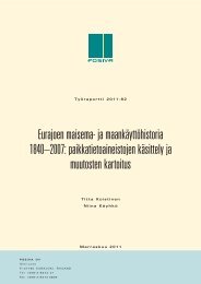
Figure 1. Copper-iron canisters for the spent fuel from the Loviisa 1-2 (VVER-440),<br />
Olkiluoto 1-2 (BWR) and Olkiluoto-3 (EPR/PWR) reactors from left to right. All variants<br />
of the canister have the same outer diameter of 1.05 m. The height of the canister<br />
ranges from 3.55 to 5.22 m. Illustration by <strong>Posiva</strong> Oy.<br />
The main documentation of the canister design in <strong>Posiva</strong> will consist of the following<br />
principal documents that will be the base for preliminary safety analysis reporting<br />
(PSAR) and the base for safety case of the long term safety to the extent that concerns<br />
that engineered barrier system (EBS) canister. See Figure 2.
11<br />
<strong>Canister</strong> production line <strong>2012</strong><br />
POSIVA <strong>2012</strong>-16<br />
<strong>Canister</strong> design <strong>2012</strong><br />
POSIVA <strong>2012</strong>-13<br />
<strong>Canister</strong> manufacture<br />
POSIVA 2009-03<br />
<strong>Canister</strong> sealing<br />
POSIVA 2010-05<br />
<strong>Canister</strong> strength<br />
SKB TR-10-28<br />
Component inspection<br />
POSIVA <strong>2012</strong>-35<br />
Weld inspection<br />
POSIVA 2010-04<br />
Corrosion resistance<br />
POSIVA 2011-01<br />
Background information on:<br />
• Material properties (SKB TR-10-28), (SKB TR-09-32), (SKBDoc 1207576),<br />
(SKB R-09-14), (SKB R-10-64)<br />
• Material models (SKB TR-10-28), (SKB TR-10-31), (SKB TR-09-32), (SKB R-09-14)<br />
• Mechanical strength (SKBDoc 1206894), (SKB R-10-11), (WR 2005-12),<br />
(SKB TR-05-18), (SKBDoc 1177857), (SKBDoc 1207429), (SKB TR-09-32)<br />
• Fracture resistance (SKBdoc 1203550), (SKBDoc 1187725), (SKBDoc 1089758),<br />
(SKB TR-10-29), (SKB R-10-11), SKBDoc 1206868<br />
• Sub-criticality (WR 2005-13)<br />
• Radiation dose rates (WR 2008-63)<br />
• Decay heat (WR 2005-71)<br />
• Thermal analyses (WR <strong>2012</strong>-56), (WR 2006-19)<br />
• Welding demonstrations (WR 2009-126)<br />
Figure 2. The principal documents that specify and qualify the canister as a component<br />
of the engineered barrier system. The main references of the principal reports are listed<br />
in the lower part of the graph and they contain the main technical information of the<br />
data and analyses.<br />
This report is also properly connected to <strong>Design</strong> Basis and Performance Assessment<br />
reports.
13<br />
2 CANISTER’S FUNCTION AS A PART OF ENGINEERED BARRIER<br />
SYSTEM OF THE KBS-3 CONCEPT<br />
The disposal system consists of the spent nuclear fuel, the canisters, the buffer, the tunnel<br />
backfill and tunnel plugs, the auxiliary components, the geosphere and the biosphere<br />
in the vicinity of the repository. According to the reference repository design, the spent<br />
fuel canisters are disposed of vertically in deposition holes in a one-storey underground<br />
facility with deposition tunnels at a depth of 400-450 m below ground (Saanio et al.<br />
<strong>2012</strong>).<br />
The safety concept for a KBS-3 repository according to <strong>Design</strong> Bases report is based on<br />
the long-term isolation and containment of the spent fuel assemblies in the canisters and<br />
on the retardation features of the disposal features in case of a release.<br />
2.1 Safety functions<br />
In accordance with the safety concept for a KBS-3 repository, safety functions are assigned<br />
to the EBS and the host rock.<br />
In <strong>Posiva</strong>'s repository concept the safety functions of the EBS components according to<br />
<strong>Design</strong> Bases report are described as follows:<br />
1) The safety function of the canister is to:<br />
Ensure a prolonged period of containment of the spent fuel. This safety function<br />
rests first and foremost on the mechanical strength of the canister’s cast<br />
iron insert and the corrosion resistance of the copper surrounding it.<br />
2) The safety functions of the buffer are to:<br />
contribute to mechanical, geochemical and hydrogeological conditions that<br />
are predictable and favourable to the canister, and to protect canisters from<br />
external processes that could compromise the safety function of containment<br />
of the spent fuel and associated radionuclides, and<br />
limit and retard radionuclide releases in the event of canister failure.<br />
3) The safety functions of the deposition tunnel backfill and plug are to:<br />
contribute to favourable and predictable mechanical, geochemical and hydrogeological<br />
conditions for the buffer and canisters,<br />
limit and retard radionuclide releases in the possible event of canister failure,<br />
and<br />
contribute to the mechanical stability of the rock adjacent to the deposition<br />
tunnels.<br />
4) The safety functions of the closure systems (backfill of underground openings<br />
other than the deposition tunnels; various plugs and seals of shafts and tunnels)<br />
are to:
14<br />
<br />
<br />
<br />
prevent the underground openings from compromising the long-term isolation<br />
of the repository from the surface environment and normal habitats for<br />
humans and other biota,<br />
contribute to favourable and predictable geochemical and hydrogeological<br />
conditions for the other engineered barriers by preventing the formation of<br />
significant water conductive flow paths through the openings, and<br />
limit and retard inflow to and release of harmful substances from the repository.<br />
According to YVL D.5 the natural barriers and their safety functions may consist of:<br />
"stable and intact rock with low groundwater flow rate around disposal canisters<br />
rock around waste emplacement rooms where low groundwater flow, reducing<br />
and also otherwise favourable groundwater chemistry and retardation of<br />
dissolved substances in rock limit the mobility of radionuclides<br />
protection provided by the host rock against natural phenomena and human<br />
actions."<br />
The surface environment is not given any safety functions; instead it is considered as<br />
the object of the protection provided by the repository system.<br />
2.2 Performance targets<br />
Performance targets are specified for the safety functions of the EBS and target properties<br />
are defined for the safety functions of the host rock. These targets indicate the extent<br />
to which a safety function is fulfilled at various times during the repository evolution.<br />
The actual performance targets for the disposal system are defined on the basis of such<br />
properties that can be derived from measurable or otherwise observable properties -for<br />
instance, with the aid of modelling.<br />
In the case of the host rock, the term "target properties" is used in place of "performance<br />
targets", since the properties of the rock are set by the natural features of the selected<br />
site and the deposition hole location. On the other hand, the repository has to be adapted<br />
to the local site conditions.<br />
The performance targets for the canister are given in Table 1, along with a summary of<br />
their rationales (for a more extensive discussion, see Performance Assessment report).
15<br />
Table 1. Performance targets for the canister, main rationale and the related design<br />
requirements according to Performance Assessment report, Table 2-1.<br />
Performance target<br />
<strong>Canister</strong> shall initially be intact<br />
when leaving the encapsulation<br />
plant for disposal except for<br />
incidental deviations.<br />
In the expected repository conditions<br />
the canister shall remain<br />
intact for hundreds of thousands<br />
of years except for incidental<br />
deviations.<br />
<strong>Canister</strong> shall withstand corrosion<br />
in the expected repository<br />
conditions.<br />
<strong>Canister</strong> shall withstand the<br />
expected mechanical loads in<br />
repository.<br />
<strong>Canister</strong> shall not impair the<br />
safety functions of other barriers.<br />
<strong>Canister</strong> shall be subcritical in<br />
all postulated operational and<br />
repository conditions including<br />
intrusion of water through<br />
damaged canister wall.<br />
The canisters shall be stored,<br />
transferred and emplaced in a<br />
way that the copper shell is not<br />
damaged.<br />
<strong>Design</strong> of the canister shall<br />
facilitate the retrievability of<br />
spent fuel assemblies from the<br />
repository.<br />
Main rationale<br />
The main safety function of the canister is containment. The<br />
performance of the welding method and NDT should be such<br />
that containment is ensured at the initial state and for as long<br />
as possible. After a period of a few hundreds of thousands of<br />
years the radiological hazard of spent fuel will be similar to<br />
the one posed by the uranium it was originally made of.<br />
Corrosion is a potential mode of canister failure.<br />
Mechanical loading is a potential cause of canister failure.<br />
Spent fuel emits heat and radiation that are potentially detrimental<br />
to the other barriers if the canister does not provide<br />
adequate shielding. Furthermore, the canister itself will inevitably<br />
undergo some chemical changes over time, the products<br />
of which should not be detrimental to the other barriers.<br />
If criticality is reached a large amount of energy is generated<br />
causing damage to the canister and other barriers and widespread<br />
release of radionuclides.<br />
If the canister is damaged the containment is endangered.<br />
As required in Decision in Principle 2000 and 2010.<br />
(M 3/2010 vp, 6.5.2010)<br />
2.3 Safety functions, performance targets and safety-related guidance to<br />
design<br />
The assessment of long-term safety is based on an understanding of the events and<br />
processes that have the potential to impair the safety functions of the disposal system.<br />
The starting point for the assessment of long-term safety is the initial state, which is<br />
defined for each canister as the conditions prevailing in the near-field when the buffer<br />
and backfill are installed (in other words, at the point when the direct influence and
16<br />
monitoring possibilities of the disposed canister and buffer has come to an end). The<br />
system is designed so that it evolves from the initial state through an early, transient<br />
phase to a long-term evolution phase, during which changes are much slower. However,<br />
during the entire regulatory compliance period, the slow changes and rare events with<br />
related uncertainties need to be taken into account.<br />
The safety assessment describes the performance and evolution of the repository over<br />
time, taking into account all known phenomena and uncertainties that affect safety. The<br />
way in which the system evolves, however, depends on its initial state, including uncertainties<br />
and potential deviations, which in turn depend on decisions taken on repository<br />
design and the implementation of such design. These decisions will be constrained by<br />
design requirements, based in part on guidance from previous performance and safety<br />
assessments. The development of the disposal system can, thereby, be considered as<br />
continuous iteration between performance assessments and design bases, as shown in<br />
Figure 3.<br />
The long-term safety assessors provide feedback and guidance to the system design<br />
concerning:<br />
<br />
<br />
indications of the need for improved engineered robustness; these may be used<br />
to increase confidence in the safety assessments; and<br />
specifications of the uncertainties and deviations that can be tolerated such that a<br />
target state is still achieved.<br />
The iteration between the design and performance assessors is to ensure, as far as possible:<br />
mutual compatibility of the engineered barriers with each other and with the<br />
bed-rock, taking into account their respective safety functions;<br />
resistance of the engineered barriers to the main thermal, hydraulic, mechanical<br />
and chemical loads to which they will be subjected during evolution of the system;<br />
and<br />
robustness with respect to slow processes and unlikely events that may occur<br />
over the regulatory compliance period.<br />
The design bases presented in Chapter 3 are based on these principles.
17<br />
Safety functions<br />
Identify the external<br />
loads/stresses<br />
<strong>Design</strong> bases<br />
<strong>Design</strong> base cases<br />
Assumption of the<br />
state of other barriers<br />
<strong>Design</strong> criteria<br />
Reference design<br />
Assumption of the<br />
design base cases of<br />
other barriers<br />
Quantitative<br />
analysis of how the<br />
loads affect on the<br />
design<br />
Sufficiency of<br />
chosen set of<br />
properties<br />
Production line<br />
reports<br />
Figure 3. The iteration process between the mechanical design development of a component<br />
and the safety assessment of the system.
19<br />
3 DESIGN BASES FOR CANISTER<br />
According to <strong>Design</strong> Bases report the system design premises comprise the objectives<br />
set for the whole system, the limitations set by the environment, technology and knowledge<br />
and the existing operating environment (regulations, responsibilities, organisations,<br />
resources). These form the starting point for the definition of the design basis of<br />
disposal operations.<br />
The design basis refers to the current and future environmentally induced loads and<br />
interactions that are taken into account in the design of the disposal system, and, ultimately,<br />
to the requirements that the planned disposal system must fulfil in order to<br />
achieve the objectives set for safety (i.e. the design premises).<br />
In defining the design basis, <strong>Posiva</strong> shall, by regulation, on the one hand, assess the<br />
likelihood of different scenarios and, on the other hand identify those deemed reasonable,<br />
and assess those that may be possible but are considered highly unlikely. Although<br />
only scenarios deemed reasonable are used as design basis scenarios, scenarios that are<br />
deemed unlikely also need to be assessed in the safety case.<br />
According to regulations (YVL D.5, paragraph 407), targets shall be specified for the<br />
performance of each safety function. Safety functions are the main roles for each barrier,<br />
from which performance targets for the engineered barriers and target properties for<br />
the host rock are defined considering their respective safety functions. Individual performance<br />
targets or target properties must be defined for each main component of the<br />
repository system (canister, buffer, filling material, repository host rock).<br />
The actual design requirements and design specifications are ultimately defined so as to<br />
enable the achievement of the performance targets in the expected scenarios. The performance<br />
targets have been set so that individual deviations or deficiencies will not endanger<br />
the long-term safety of the whole disposal system. The performance targets form<br />
the basis for the definition and implementation of the design requirements. The initial<br />
state of the disposal system can be affected through the design requirements and system<br />
implementation methods (up to the closing and sealing of each deposition hole or tunnel);<br />
the degree to which the performance targets are met and the capability of the system<br />
as whole to effectively isolate the radionuclides from the living environment is<br />
evaluated through the assessment of the design basis scenarios of the evolution of the<br />
disposal system.<br />
Together with a number of issues determined by operational safety, environmental factors,<br />
operational efficiency and quality assurance, it is the safety functions and performance<br />
targets that govern the design bases of the canister. From these, the design and<br />
implementation requirements and specifications have then been deducted on the basis of<br />
development work and research data. The canister shall be designed in such a manner<br />
that it meets the specified design requirements and manufactured in such a manner that<br />
it fulfils the respective design specifications. The design base requirements are compiled<br />
from the statements given in (YVL D.5; YVL D.3) and the retrievability is stated in the<br />
Finnish Government Decision 478/1999.
20<br />
These design bases lead furthermore to some design requirements of the canister design,<br />
dimensions, material selection, metallurgical properties and chemical contents. The<br />
bases also lead to some design requirements of the internal atmosphere, chemical<br />
content and temperature of the canister void and internals. These are discussed later in<br />
chapter 14 where the compliance with the requirements is assessed.<br />
The quantitative canister design specifications derived from design requirements are the<br />
principal target and output of this design report.<br />
3.1 Sub-system requirements – <strong>Canister</strong><br />
Definition and objectives<br />
<strong>Canister</strong> is a container with a water and gas tight shell and a mechanical loadbearing<br />
insert in which the spent nuclear fuel is placed for final disposal in the repository. The<br />
canister shall contain the spent fuel and prevent, and in the case of a leak, limit the<br />
spreading of radioactive substances into the environment.<br />
Containment<br />
<strong>Canister</strong> shall initially be intact when leaving the encapsulation plant for disposal except<br />
for incidental deviations.<br />
In the expected repository conditions the canister shall remain intact for hundreds of<br />
thousands of years except for incidental deviations.<br />
Chemically resistant<br />
<strong>Canister</strong> shall withstand corrosion in the expected repository conditions.<br />
Mechanically resistant<br />
The canister shall withstand the expected mechanical loads in repository.<br />
Compatibility with the EBS and host-rock performance<br />
The canister shall not impair the safety functions of other barriers.<br />
Sub-criticality<br />
The canister shall be sub-critical in all postulated operational and repository conditions<br />
including intrusion of water through damaged canister wall.<br />
Handling before disposal<br />
The canisters shall be stored, transferred and emplaced in a way that the copper shell is<br />
not damaged.
21<br />
Retrievability<br />
<strong>Design</strong> of the canister shall facilitate the retrievability of spent fuel assemblies from the<br />
repository.<br />
Safeguards<br />
Encapsulation and disposal of the spent fuel shall be organised in a way that makes the<br />
safeguards control of the nuclear material possible according to requirements of (YVL<br />
D.5, Section 5.4).<br />
3.2 <strong>Design</strong> requirements – <strong>Canister</strong><br />
Definition<br />
The canister is composed of a leak-tight copper shell and of a load-bearing nodular cast<br />
iron insert.<br />
3.2.1 <strong>Canister</strong> performance<br />
Chemically resistant<br />
The copper overpack shall provide the corrosion resistance required in the postulated<br />
repository.<br />
Mechanical strength<br />
The iron insert shall provide the mechanical strength required.<br />
Sub-criticality<br />
To ensure sub-criticality, the properties (e.g., enrichment, burnup) of the fuel inside the<br />
canisters, as well as the internal geometry of the insert, shall be known precisely enough<br />
to reach a high degree of confidence in criticality safety.<br />
Limitation of radiation level<br />
The shielding provided by the canister shall limit the dose rate to minimise radiolysis of<br />
water outside the canister.<br />
The fuel elements for encapsulation shall be selected in a pre-planned, controlled and<br />
documented way to limit the radiation dose on the canister surface.<br />
Limitation of heat generation<br />
The heat generation inside the canister shall be limited in a way that the performance of<br />
the other barriers is not impaired.
22<br />
The fuel elements for encapsulation shall be selected in a pre-planned, controlled and<br />
documented way to meet the decay heat limit set for each canister type.<br />
Thermal conductivity<br />
The canister materials shall have sufficient thermal conductivity so that the heat from<br />
the spent nuclear fuel is effectively dissipated.<br />
<strong>Canister</strong> geometry<br />
The copper overpack and insert shall be dimensioned to that the insert can be installed<br />
into the copper overpack.<br />
3.2.2 Copper overpack requirements<br />
Copper overpack is composed of a copper lid and a bottom welded into a copper tube or<br />
of a copper lid welded into a copper tube with an integrated bottom.<br />
Properties of the weld shall fulfil the same performance requirements as the rest of the<br />
copper shell.<br />
Corrosion resistance<br />
The design, manufacturing and any further processing and handling of the canister shall<br />
aim at limiting the risk for stress corrosion cracking in repository conditions.<br />
Lifting and transfer<br />
The copper overpack shall be designed to bear the load from canister handling and<br />
transfer.<br />
Dent marks and scratches on the copper surface shall be minimised during canister handling<br />
and transport.<br />
Copper overpack ductility<br />
The canister copper overpack shall be designed to withstand the plastic deformation and<br />
creep caused by any postulated mechanical or thermal load.<br />
3.2.3 Cast iron insert requirements<br />
Sub-criticality<br />
The insert geometry and acceptance criteria for soundness shall be set so that subcriticality<br />
is guaranteed.<br />
Mechanical strength<br />
The canister insert shall be designed to bear the hydrostatic pressure from groundwater<br />
and from swelling of bentonite.
23<br />
The canister insert shall be designed to bear the hydrostatic load caused by glaciation.<br />
The canister insert shall be designed to bear unevenly distributed swelling loads.<br />
The canister insert shall be designed to bear the loads from the postulated rock shear<br />
displacements in the deposition hole.
25<br />
4 DESIGN LOADS<br />
<strong>Design</strong> loads for the canister structure are mechanical loads (pressure, local forces or<br />
forced displacements), thermal loads (varying temperature in time or position), chemical<br />
loads (chemical around the canister environment, including bacteria-induced chemical<br />
loads) and radiation load (radiation embrittlement).<br />
4.1 Handling loads<br />
The lifting equipment and the shoulder in the copper lid collar and the whole of copper<br />
overpack shall be dimensioned for the gravity load of the loaded canister weight multiplied<br />
by the dynamic factor of lifting loads and required safety factor. During the encapsulation<br />
process the canister is supported from the bottom lid until the point, where canister is transferred<br />
from the encapsulation line trolley cradle onto the automatic guided crawler. At that<br />
time and when the canister is loaded into the canister installation vehicle and installed into<br />
the deposition hole, the canister is gripped and lifted from the lifting collar in the copper<br />
lid. In these three cases all the canister weight is hinged on the copper lid collar only.<br />
Description of canister handling in encapsulation plant is given in (Kukkola <strong>2012</strong>, chapter<br />
2). Basic dimensioning of the lifting shoulder is analysed in Section 8.3.2. The masses of<br />
all variant canisters are given in Table 6, in Section 6 of this report. <strong>Canister</strong> lid lifting<br />
shoulder strength including the effect of postulated cracks is assessed in the strength analysis<br />
reports (Raiko et al. 2010) and originally in (Bolinder 2009).<br />
<strong>Canister</strong> lifting from the lid collar is also necessary if the retrieval of the canister out of the<br />
deposition hole becomes necessary. In such a case, the saturated and swollen bentonite is<br />
first dissolved with high saline water and the canister is lifted up with normal type gripper<br />
from the top lid collar. In this case the lifting load is not higher than during encapsulation,<br />
vice versa, the buoyancy caused by the dissolving water makes the canister about 4 tons<br />
lighter than as it is submerged. The retrieval of a disposed canister has been planned in<br />
principle several years ago (Saanio & Raiko 1999). The important international test for<br />
<strong>Posiva</strong>’s demonstration on this topic has been the canister retrieval test made by SKB at<br />
Äspö in 2006. As a main conclusion the freeing trial showed that the tested method<br />
works. The retrieval operations in various phases of disposal are described in (Saanio et<br />
al. <strong>2012</strong>, Section 5.4).<br />
4.2 Incidents and accidents during encapsulation, transfer and disposal<br />
The leading principle in encapsulation and disposal of spent fuel is that in case of incidents<br />
or accidents that faces the canister the disposal process is halted for assessment of<br />
possible damages caused on the canister. In case effective damages are detected or assessed,<br />
the canister will be reversed in the process chain back to encapsulation station,<br />
the outer lid will be machined loose and decoupled, and the canister will be docked to<br />
the fuel handling chamber. After that the inner steel lid can be opened and removed with<br />
the normal handling equipment in the chamber. After opening the canister, the fuel assemblies<br />
are moved one by one from the canister into a temporary store in a drying vessel<br />
inside the fuel handling chamber. Then the empty canister is loosened from the<br />
docking station, transferred backwards below the receiving hall, wrapped in a contami-
26<br />
nation protection foil and lifted up with a canister transport cradle into the receiving hall<br />
for further repair or scrapping process. For details, see (Kukkola <strong>2012</strong>, Sections 2.5.3<br />
and 2.5.4).<br />
The encapsulation and canister transfer process is planned in a way that canister cannot<br />
fall or be dropped from a remarkable height as a result of single failure of an active<br />
member or device of the canister lifting or transferring systems. <strong>Canister</strong> lifts are single<br />
failure secured (reduplicated) for active components and the static components are accurately<br />
designed and dimensioned against all postulated loads, thus the probability of<br />
canister falling accident is very low.<br />
The canister behaviour during a transport vehicle fire is analysed in (Lautkaski et al.<br />
2003). In the case of vehicle fire, the temperature is not high enough to damage the canister<br />
or fuel inside the canister, when the canister is inside the radiation shield cylinder<br />
of the canister transfer vehicle. The analysis was made assuming the vehicle with heavy<br />
rubber tires, but the vehicle fire load can be decreased using a crawler-type vehicle<br />
equipped with tracks instead of rubber wheels. Thus the actual fire safety can be even<br />
better if no rubber wheels are used.<br />
Overall operational safety in encapsulation plant and in repository is analysed and<br />
shown to fulfil the national nuclear safety regulation in (Rossi & Suolanen <strong>2012</strong>).<br />
In the worst accident cases the canister is assumed to break and all the fuel inside the<br />
canister is assumed to be damaged. Even in the worst case, the radioactive releases outside<br />
the plant do not exceed the safety limits of the regulation. Thus the operational<br />
safety does not set any special or definite conditions for canister strength.<br />
The leading design principle in canister handling accidents is as follows. The disposal<br />
canister is not designed to maintain its long term properties after a major handling or<br />
transport incident or accident in operation phase. If such accident happens, the canister<br />
will be returned to the encapsulation plant, opened and unloaded, and the fuel will be reencapsulated<br />
into an intact canister.<br />
4.3 Internal loads<br />
The spent fuel itself produces He-gas as a result of radioactive decay. The pressure generated<br />
from this process in long-term is, however, lower than the external hydrostatic<br />
pressure according to (Miller & Marcos 2007, Section 3.2.9), thus this process can be<br />
ignored as a mechanical load.<br />
Corrosion of the insert can generate H 2 -gas inside the canister, but this is possible only<br />
after the canister has been breached and the water is filling the void inside canister according<br />
to (Miller & Marcos 2007). Gas generation inside a leaking canister is not causing<br />
any additional pressure load, because, due to leak, all pressure difference loads are<br />
vanished.<br />
The residual water trapped inside the canister during encapsulation might form nitrogen<br />
acids with help of possible N 2 -gas and the radiation. These acids might cause anaerobic<br />
corrosion inside a closed canister according to (Miller & Marcos 2007). To avoid this
27<br />
risk, the canister inside atmosphere is changed from air to inert argon-gas (Ar) during<br />
encapsulation and the amount of existing residual water in the fuel assemblies is minimised<br />
through drying process during encapsulation. Thus even this type of corrosion<br />
and gas production in such amount that could cause remarkable internal pressure load<br />
can be ignored. The encapsulation process is generally described in (Kukkola <strong>2012</strong>).<br />
The insert with flat lids will be pressurised up to an internal overpressure of 0.1 MPa. This<br />
is the load case during the encapsulation process when the normal atmospheric pressure of<br />
inert gas is prevailing inside the insert and the canister is in a vacuum chamber for the<br />
EBW of the copper lid. This load case is not applicable in case of the alternative welding<br />
method FSW. FSW is made in normal atmospheric pressure. The flat lids are primarily<br />
dimensioned for external pressure of 45 MPa. The only detail that needs to be examined<br />
for this internal pressure load case during EBW welding is the top lid central screw and the<br />
gaskets. During welding, all the pressure of the inside inert gas is loading the central screw<br />
of M30 mm. M30 stands for a metric ISO standard screw thread and it is designated by<br />
the letter M followed by the value of the nominal diameter in millimetres. The screw<br />
calculation is given in Section 8.3.2.<br />
The decay heat generation in canisters will depend on the amount, burnup, operational<br />
history and cooling time of the fuel. The initial decay heat load in a canister is limited in<br />
safety case assumptions to 1700 W (SKB 2009) in reference case for BWR canister. Accordingly,<br />
the power limits are set for VVER-440 and EPR/PWR canisters as 1370 W and<br />
1830 W, respectively. These numbers are derived from the reference design by weighting<br />
with the respective canister’s cooling surface area; see Table 6 for surface areas. The thermal<br />
conductivity of the copper body of the canister is two orders of magnitude higher than<br />
the conductivity of the surrounding bentonite and rock in the repository. Therefore the<br />
metallic canister surface will be practically at a uniform temperature and most of the thermal<br />
gradient will exist in the bentonite and rock around the canister and in possible air<br />
gaps between the solid material interfaces.<br />
High neutron and gamma-radiation dose may cause embrittlement in the insert material.<br />
Secondly, a too high gamma radiation dose rate outside canister may cause radiolysis in<br />
the surrounding water, which may lead to increasing corrosion on the outer surface of the<br />
canister or make changes in bentonite buffer. That is why the allowable dose rate on canister<br />
surface is limited to 1 Gy/h to avoid excessive radiolysis of water outside canister.<br />
These phenomena will be discussed more in Section 8.8 of this report.<br />
The maximum fuel rod temperature inside the canister is estimated with numerical analyses<br />
in (Ikonen 2006) to be about +230 °C. This is calculated assuming radiation heat transfer<br />
and conduction through the Ar-gas between the fuel rods and the canister insert, when<br />
the canister surface temperature is conservatively +100 °C. The 1.5 mm gap between the<br />
insert and the copper overpack is also assumed to act as an isolator over which gap the<br />
thermal flow is transferred by radiation only, because the gap may be in vacuum after the<br />
EB-weld process for a while. The thermal expansion of various canister components will<br />
be discussed later in Section 8.4.3 in this report.<br />
If FSW sealing method is used instead of EBW, then the gap between insert and shell is air<br />
filled with normal atmospheric pressure and the conductivity over the gap is initially re-
28<br />
markably better and leads to lower maximum temperature in the insert and fuel. Thermal<br />
conduction phenomena inside a canister are analysed and discussed in (Ikonen 2006). It is<br />
worth noting that this particular analysis is made to ensure the fuel integrity after encapsulation<br />
and it may be overly conservative in respect of insert temperature. In Section 8.4.2<br />
there is made a more realistic comparison calculation of insert temperature between FSW<br />
and EBW sealed canisters.<br />
Excessive heat flow might lead to too high temperature in the canister components, which<br />
may lead to unwanted chemical processes, excessive thermal deformations, strains and<br />
stresses and change of material properties. The thermal properties of all the cooling chain<br />
from fuel rods inside the insert up to ground surface above the repository govern the<br />
maximum allowable decay power that can be accepted without of risk for local overheating.<br />
The cooling chain is described in details for ex. in (Miller & Marcos 2007). The cooling<br />
analyses of disposed canisters including the definition of minimum distances between<br />
the canisters in repository are made and reported in (Ikonen & Raiko <strong>2012</strong>).<br />
4.4 External mechanical loads<br />
Mechanical external loads come from the natural environment and from the behaviour<br />
of the surrounding bentonite buffer. The depth of the Olkiluoto repository is defined to<br />
be 400 - 450 m and the nominal depth is 420 m. Thus the maximum groundwater hydrostatic<br />
pressure is 4.1 MPa. The maximum postulated 2.5 km ice layer during glaciation<br />
at Olkiluoto area according to (Pimenoff et al. 2011). This 2.5 km ice sheet may<br />
create an additional pressure of about 25 MPa to the groundwater pressure, if the effect<br />
of ice layer is conservatively added to the hydrostatic pressure of the groundwater. The<br />
bentonite buffer swells, when the bentonite is getting water-saturated. The wetting of<br />
the bentonite buffer is expected to take place gradually after the deposition tunnel backfilling<br />
and closing within some months or years depending on water inflow rate into the<br />
tunnel and deposition holes. The bentonite swelling pressure is strongly dependent on<br />
the final density of the buffer. The salinity of the absorbed water also affects swelling.<br />
The specified final density for the buffer is 1950-2050 kg/m 3 (<strong>Design</strong> Bases, Section<br />
5.5). This leads to a swelling pressure of 2-10 MPa, respectively, according to (Börgesson<br />
et al. 2009). The maximum swelling pressure of bentonite depends on the density<br />
and the chemical contents of the bentonite. In long term, the chemical contents of the<br />
Na-bentonite may change. The Na-ion may be changed to Ca-ion. Ca-bentonite has a<br />
remarkably higher swelling pressure than the Na-bentonite, up to 15 MPa in the high<br />
density region, e.g. at a montmorillonite content of 0.83 and a saturated density of 2050<br />
kg/m 3 (Karnland 2010, page 27). As a summary, the enveloping maximum sum of<br />
isostatic pressure load for a canister at Olkiluoto site is about 44 MPa.<br />
In Forsmark, Sweden, the design pressure for the canister has been taken as 45 MPa by<br />
SKB. It is slightly higher than the calculated design pressure load at Olkiluoto area,<br />
thus, when referring to the respective SKB strength analyses, Olkiluoto has some additional<br />
safety margin in the assessment of the loads. All the referenced SKB strength<br />
analyses are made using 45 MPa as the design pressure.<br />
The bentonite swelling pressure can be somewhat unevenly developed and distributed,<br />
especially during the water uptake in the early evolution but also in saturated condition,
29<br />
if the dimensional tolerances of the deposition hole and the density of the bentonite are<br />
remarkably variable. In earlier load specifications, (Raiko 2005) and (SKB 2006a), the<br />
unevenly distributed swelling loads have been overly conservative assumptions. The<br />
absolutely rigid supports and restraints assumed in the load specifications are mechanically<br />
unfeasible in reality. It is essential to note that the swelling pressure of the bentonite<br />
induces the strength of bentonite, but the strength is less than the pressure, see<br />
material model for bentonite in Chapter 7.4.<br />
The bentonite buffer applies a load on the canister and supports it inside the deposition<br />
hole. The bentonite buffer has the same swelling properties on the locations of the postulated<br />
load and on the location of the postulated support or reaction force; thus, the<br />
maximum pressure acting on the canister surface inside bentonite buffer is limited to the<br />
sum of hydrostatic pressure and the swelling pressure and, furthermore, the vectorial<br />
sum of loads and supporting reaction forces have to be statically in balance. These<br />
specifications lead to the following type of unevenly distributed load schemes for the<br />
canister, which causes the maximum bending load on the canister, see Figure 4. The<br />
derivation of the determining load cases in bentonite buffer wetting phase and during<br />
saturated period are given in (Börgesson et al. 2009). The stressing effects due to the<br />
maximum load cases are also preliminarily assessed in the same report.<br />
Area 1 p<br />
Area 3<br />
p<br />
L/4<br />
L/8<br />
Area 2<br />
L·(½-⅛)<br />
L/4<br />
Figure 4. The most unfavourable swelling pressure distribution causing bending (Börgesson<br />
et al. 2009).<br />
The same report (Börgesson et al. 2009) also gives a heaviest load case expected from<br />
the unevenly distributed swelling pressure for the copper overpack. This is the case,<br />
where swelling pressure is different on top and bottom end of the canister and the shear<br />
force from the radial swelling pressure will balance the canister loading. This load type<br />
is shown in Figure 5.
30<br />
MPa<br />
<br />
<br />
2 = 573 kPa<br />
m<br />
<br />
<br />
1 =2550 kPa<br />
MPa<br />
Figure 5. The most unfavourable buffer swelling pressure distribution that causes shear<br />
(Börgesson et al. 2009).<br />
Figure 6. Rock shear load case variations for the canister according to the analysed<br />
cases of (Hernelind 2010). Rock shear is a rare upset loading condition that may ask<br />
for the most demanding deformation capability.
31<br />
The integrity of the canister can be damaged due to shear-type rock movements if the<br />
shear plane accidentally intersects the deposition hole and the shear amplitude is large<br />
enough (see Figure 6 for load case variations). If the bentonite buffer (assumed to have<br />
been transformed to Ca-bentonite) around the canister is 350 mm thick it is required to<br />
withstand a rock shear of 5 cm with a velocity of 1 m/s according to (SKB 2009, Section<br />
3.1.2). The bentonite material properties and swelling pressure is described in<br />
(Börgesson et al. 2010). The risk caused by even larger rock movements, which may<br />
occur during the melting phase of a major continental glacier, is minimised to allowable<br />
level by locating the disposal gallery within justified respect distances outside major<br />
fracture zones in the bedrock and by locating the deposition holes in such a way that is<br />
not intersected by fractures with potential to undergo damaging shear movements (Hellä<br />
et al. 2009). When the actual canister deposition hole positions are selected outside the<br />
existing major fracture zones, the canisters will be exposed only to possible secondary<br />
(new) fractures generated during future shear movement.<br />
The possible presence of permafrost at repository depth is considered in the formulation<br />
of scenarios (Marcos et al. 2011). For canister design assessment purposes, permafrost is<br />
assumed to extend down to the repository level. The lowest temperature is assumed to be<br />
-5 °C, at lowest. The low temperature of bentonite and water in it may lead to changes in<br />
swelling pressure. This exceptional load phenomenon is assessed in Section 8.4.4.<br />
4.5 External chemical loads<br />
Chemical loads (corrosion) and effect of bacteria may cause some degradation of the leaktight<br />
copper overpack structure in the long period perspective of time. The degradation<br />
processes are assessed in postulated environmental evolution conditions. The chemical<br />
corrosion resistance of the copper canister is discussed in this report in Section 8.9.<br />
4.6 Mechanical load combination<br />
The mechanical loads described above can be grouped as follows. The typical time of<br />
occurrence is noted at the end of each type of load category.<br />
1 Isostatic or asymmetric swelling pressure loads due to incomplete even or uneven<br />
water saturation in Na-bentonite (effective local swelling pressure ~7.8<br />
MPa), possible time of occurrence (0-100 y)<br />
2 Asymmetric loads in saturated Ca-transformed-bentonite due to manufacturing<br />
tolerances of deposition hole and of buffer density (swelling pressure difference<br />
~7.8 MPa) (100 y - glaciation)<br />
3 Groundwater pressure at the depth of repository (4.1 MPa) (100 y - glaciation)<br />
4 Glacial pressure from 2.5 km thick glacier (25 MPa) (glaciation period)<br />
5 Shear load due to rock displacement (5 cm, v=1 m/s) (permafrost and glaciation<br />
period or later)<br />
6 Combination of 2 + 3 (100 y - glaciation)<br />
7 Combination of 2 + 4 (glaciation period)
32<br />
8 Combination of 3 + 5 (before or after glaciation period)<br />
9 Combination of 4 + 5 (glaciation period)<br />
10 Lifting loads in operation phase (canister weight + dynamic extras)<br />
11 Buffer swelling at lowest temperature -5 °C (glaciation period).<br />
The temperature of the canister copper overpack will stay above room temperature<br />
about 10000 years after deposition and then the temperature will slowly go down to<br />
natural temperature of the Olkiluoto rock (10-11°C) within a few thousand years.<br />
Around glaciation, before or after, the canister temperature may be lowered to close to 0<br />
°C, if the cold period is long enough and there is not protecting glaciation or snow on<br />
the ground. As a design assessment exercise, the repository level temperature is assumed<br />
to go down to -5 °C. More details of the temperature evolution of the canister are<br />
given in (Pastina & Hellä 2006, chapter 6.1). A detailed graph of calculated canister<br />
surface temperature is given also in Figure 28 in Section 8.4.3 of this report. It clearly<br />
shows the effect of bentonite buffer saturation rate in early years of the evolution in the<br />
repository. This graph does not include the possible permafrost effects but assumes the<br />
ground surface conditions to be unchanged. In safety case, the onset of the first cold<br />
period is expected at about 50000 years with temperature and precipitation changes<br />
leading to first permafrost development and later on to ice-sheet growth and advance<br />
(Pimenoff et al. 2011).<br />
Load types of 10 and 11 (above) are handled separately without any combinations. The<br />
exceptionally low temperature of the bentonite buffer is lowering the swelling pressure,<br />
thus there is no reason to recalculate any load combinations, for assessment see Section<br />
8.4.4. The appearance and combination of various basic load cases and respective temperature<br />
range are described in Table 2.<br />
The saturation time of the bentonite buffer depends locally on wetting conditions. The<br />
time for full saturation may vary considerably. The expected reference scenario for climate<br />
evolution is given in detail in Chapter 4 of Performance Assessment report.<br />
The maximum insert temperature of the canister may vary a bit depending on the canister<br />
sealing method. If EBW is used, the gap between insert and the copper overpack<br />
may stay in vacuum for some time after welding. The vacuum causes lower heat conductivity<br />
over the gap. If FSW is used, the gap stays is atmospheric gas pressure all<br />
time. In long perspective the conditions will be equal in both canister seal variations due<br />
to gas diffusion through the insert lid gasket. The copper overpack temperature is not<br />
depending on the conditions inside canister, because the very high thermal conductivity<br />
of copper makes the temperature field even in thick copper shell.
33<br />
Table 2. The canister loads extracted from postulated repository evolution. Loads that may act simultaneously shall be combined. Coloured<br />
boxes correspond to the possible periods for appearance of the load case (1…5) in question.<br />
Repository evolution phase<br />
The reference scenario for climate evolution is referenced<br />
in the text in this Section<br />
Water saturation<br />
0 a. – 100 a.<br />
<strong>Canister</strong> temperature (°C) (EBW-sealed) < 140/100<br />
Load case number Deformation rate (Fe/Cu parts)<br />
1) Asymmetric loads due to uneven<br />
water saturation and imperfections<br />
in deposition hole geometry. No<br />
simultaneous hydrostatic pressure.<br />
Uneven water saturation effects<br />
will decay later and be replaced by<br />
permanent loads 2) and 3) acting in<br />
saturated condition.<br />
2) Permanent asymmetric loads due<br />
to uneven bentonite density and<br />
imperfections in deposition hole<br />
geometry.<br />
3) Groundwater hydrostatic pressure<br />
+ even isostatic swelling pressure<br />
of bentonite.<br />
4) Glacial pressure (additional isostatic<br />
pressure, only during glacial<br />
period).<br />
5) A shear displacement exceeding<br />
5 cm at shear velocity higher than 1<br />
m/s in fractures intersecting a canister.<br />
Insert<br />
Static<br />
Copper overpack<br />
Creep or static<br />
Insert<br />
Static<br />
Copper overpack<br />
Creep or static<br />
Insert<br />
Static<br />
Copper overpack<br />
Creep or static<br />
Insert<br />
Short-time forced<br />
displacement<br />
Copper overpack<br />
Short-time forced<br />
displacement<br />
Water saturation effects<br />
are assumed to reach<br />
their maximum.<br />
Load 1) can create<br />
bending loads<br />
Load 1) can create<br />
compressive loads<br />
Temperate<br />
100 a. – 50 ka.<br />
Permafrost Glacial Subsequent<br />
permafrost and<br />
glacial periods<br />
100/70 > T > 15 15 > T > 0* 15 > T > 0 15 > T > 0<br />
*Disturbance, -5 o<br />
Bending loads from<br />
load 2) and compressive<br />
isostatic loads<br />
from load 3)<br />
Uneven pressure loads<br />
from load 2) and<br />
isostatic loads from<br />
load 3)<br />
Loads 2) and 3)<br />
are expected to<br />
act throughout the<br />
analysis period<br />
Loads 2) and 3)<br />
are expected to<br />
act throughout the<br />
analysis period<br />
Load 4) will<br />
cause additional<br />
isostatic pressure<br />
on insert<br />
Load 4) will<br />
cause additional<br />
isostatic pressure<br />
on shell<br />
Load 5) is of<br />
most concern in<br />
end-glacial<br />
periods<br />
Permafrost and<br />
glacial conditions<br />
are to reappear
35<br />
5 NUCLEAR SAFETY CLASSIFICATION OF THE CANISTER<br />
Systems, structures and components important to safety shall be designed, manufactured,<br />
installed and operated in such a way that their quality level and the inspections and tests<br />
needed to verify their quality level are commensurate with the importance to safety of each<br />
item.<br />
According to the YVL-guide B.2 components shall be assigned to safety class 2, if their<br />
failure to operate would cause a considerable risk of uncontrolled criticality. On the other<br />
hand, components shall be assigned to safety class 3, if their fault or failure would prevent<br />
decay heat removal from spent fuel, or cause the dispersal of radioactive material.<br />
The appendix of the YVL-guide B.2 gives an example that the storage racks for fresh and<br />
spent fuel are assigned to safety class 2 and the storage of spent fuel and liquid wastes,<br />
including pools and tanks, are assigned to safety class 3.<br />
Basing on the rules and examples given in the YVL-guides B.2 and D.3 it can be concluded<br />
that the canister as a whole system shall be classified as safety class 2. The canister<br />
insert as a component shall be classified in safety class 2, because it has a prominent role in<br />
criticality safety. The canister overpack could be classified according the rules in safety<br />
class 3 as a barrier against dispersal of radioactive material. However, the especially long<br />
postulated lifetime of the copper overpack is responded according to requirements of YVL<br />
D.3 by increasing the safety classification up to class 2. The overpack consists of copper<br />
overpack components and the sealing weld.<br />
The steel lid of the insert is also classified in the safety class 2 like the insert body. The lids<br />
are active mechanical load bearing members of the system. However, the fixing screw of<br />
the insert lid is not safety related component and the gaskets of the lid have no requirements<br />
in long term tightness or sub-criticality. These auxiliary components are classified as<br />
safety class 3.<br />
In practice, the safety classification governs the scope of design analyses and the quality<br />
controls of the canister component manufacture.
37<br />
6 CANISTER SHAPE, DIMENSIONS AND SURFACE QUALITY<br />
The canisters size and shape have been derived on one hand from the space needed for<br />
the actual spent fuel assemblies, and on the other hand from the mechanical strength,<br />
radiation shielding and cooling capability. Economic optimisation has led to maximise<br />
the number of the positions for assemblies in the canister and to minimise the size (or<br />
weight) of the canister. Striving for these goals, the canister design has evolved over<br />
several stages to result in the current reference canister design. In the following, the<br />
detailed dimensions of the BWR canister are given in Figures 7 to 9 and Tables 3 to 5.<br />
The dimensioning of the reference design fulfils the design bases given in chapter 3 of<br />
this report. The design of the insert steel lid is still under consideration. The originally<br />
planned gasket construction, a rubber O-ring, see Figure 8, is not acceptable as an organic<br />
material inside canister. The new insert lid proposal is given in Figure 16, but the<br />
non-organic gasket material has not yet been decided.<br />
In Finland, there are three variants of the canister, one for each spent fuel type: BWR,<br />
VVER-440 and EPR/PWR (Figure 1). The spent fuel is sealed in the canisters as whole<br />
fuel assemblies including the fuel channel outside the VVER-440 and BWR fuel elements.<br />
The copper overpack is identical for all three variants with the exception of<br />
length. The cast iron insert for different variants has, accordingly, different length depending<br />
on the actual length of the fuel elements in question. In addition, the fuel elements<br />
have various size and shapes in cross section, too. Thus the various inserts have<br />
different shapes and size openings for the fuel elements. The dimensions of various fuel<br />
element types are given in Section 13.1. The canister variants are shown in Figures 10<br />
to 13 and the main dimensions and masses are given in Table 6.<br />
The sealing method of the copper canister has not yet been decided. The reference solution<br />
is the EB welding and the alternative method is the FS welding. Figure 15 shows<br />
the dimensions of the EB weld and Table 5 gives geometric dimensions for both alternatives.<br />
Also, there are two possible alternatives for the copper overpack manufacture, namely<br />
cylinder with an integral (flat) bottom, or a tube with a welded bottom end. The latter is<br />
made by welding the bottom end likely with FSW method. In this case the bottom lid<br />
will have additional extension on edge area like the top end lid. This makes the weldedbottom-lid<br />
canister variant 75 mm longer than the integrated flat bottom variant. The<br />
main dimensions for both variants are given in Tables 5 and 6.<br />
The <strong>Posiva</strong> reference design for the canister is the BWR-type canister. The reference<br />
design has an integrated bottom in the insert and in the copper overpack. However, there<br />
are alternative options for manufacture, such as welded bottom for the copper overpack<br />
and three optional manufacturing methods for the hot deformation of the copper tube.<br />
The alternative to the reference sealing method for the copper overpack, the EBW<br />
method, is the FSW method. Furthermore, the reference disposal method, KBS3-V, has<br />
an alternative option of the horizontal deposition, KBS3-H, but this possible option has<br />
no practical effects on canister design or load processes. KBS3-H is generally described<br />
in (<strong>Posiva</strong> 2008, pages 6-7).
38<br />
The identification of sealed canisters for bookkeeping, quality control and safeguards<br />
purposes will be implemented by visible identification label (serial number) that will be<br />
engraved in clear characters on the frontal surface of the lift shoulder. The size of the<br />
characters will be about 10 mm. The location of the identification label is defined so<br />
that it is easy to detect with cameras and, on the other hand, the engraving does not degrade<br />
the corrosion resistance of the canister. The identification string location is<br />
marked in Figure 15.<br />
Figure 7. <strong>Canister</strong> insert dimensions. SKB illustration from (Raiko et al. 2010)
39<br />
Table 3. Functional dimensions of BWR, VVER 440 and EPR/PWR canister insert with<br />
tolerances. The dimensions refer as for BWR insert to Figure 7.<br />
Dimension Description Nominal value Tolerance Reason<br />
A<br />
total length with<br />
steel lid<br />
4565 mm<br />
3365 mm<br />
5035 mm<br />
B bottom thickness 60 mm*<br />
70 mm*<br />
85 mm*<br />
C inside length 4450 mm<br />
3245 mm<br />
4900 mm<br />
+0/-0.5 mm<br />
+0/-0.5 mm<br />
+0/-0.5 mm<br />
+10.1/-5.6 mm<br />
+10.1/-5.6 mm<br />
+10.1/-5.6 mm<br />
+5/-10 mm<br />
+5/-10 mm<br />
+5/-10 mm<br />
gap for thermal<br />
expansion<br />
strength<br />
fuel geometry<br />
D outer diameter 949 mm +0.5/-0 mm strength, thermal<br />
expansion<br />
H neck thickness 33.3 mm<br />
45.6 mm<br />
50 mm<br />
I outer radius 20 mm<br />
(D193.7 mm)<br />
25 mm<br />
J<br />
calculated distance<br />
210 mm<br />
210 mm<br />
360 mm<br />
K thickness 30 mm<br />
16.2 mm<br />
100 mm<br />
L inner width**** 160 x 160 mm<br />
D173.7 mm<br />
235 x 235 mm<br />
M profile thickness 10 mm<br />
10 mm<br />
12.5 mm<br />
+10/-10 mm**<br />
+10/-10 mm**<br />
+10/-10 mm**<br />
+5/-5 mm<br />
-<br />
+5/-5 mm<br />
+1/-4 mm<br />
+1/-4 mm<br />
+3.6/-3.6 mm<br />
+2.7/-4.6 mm<br />
+2.7/-4.6 mm<br />
+5/-5 mm<br />
+3.8/-3.8 mm<br />
gauge D168 mm<br />
+5.1/-5.1 mm<br />
+1/-1 mm<br />
+1/-1 mm<br />
+1.25/-1.25 mm<br />
strength<br />
strength<br />
sub-criticality<br />
strength, subcriticality<br />
fuel geometry<br />
stiffness<br />
N lifting eye hole M48*** - 2 lifting eyes<br />
*) The total bottom thickness is the sum of cast iron thickness and the steel cassette bottom<br />
plate thickness.<br />
**) Local tolerance. The eccentricity (variation between opposite neck average thicknesses) of<br />
the structure may be +5/-5 mm.<br />
***) Threaded lifting eye hole (the size is metric thread with diameter 48 mm).<br />
****) The width and straightness of the openings are gauged, respectively, with 152 mm,<br />
Ø168 mm and 224 mm full length gauge.
40<br />
Figure 8. Principal scheme of the steel lid of the insert and the dimensions. This is a<br />
SKB illustration from (Raiko et al. 2010). The lid and gasket system is under reconsideration.<br />
See Figure 16 for a <strong>Posiva</strong> design draft.<br />
Table 4. Functional dimensions of canister insert lid with tolerances. The insert lid gasket<br />
system is still under re-consideration.<br />
Dimension Description Nominal value Tolerance Reason<br />
E diameter 910 mm +0/-0.09 mm assembly<br />
F thickness 50 mm +0.1/-0.1 mm strength<br />
G bevel angle 5° - assembly
41<br />
Figure 9. The copper overpack of the canister. SKB illustration from (Raiko et al.<br />
2010). Manufacturing and functional dimensions of the FSW variant of copper overpack.<br />
The dimensions of EBW version are the same, but the weld orientation differs.<br />
Table 5. Functional dimensions of the canister overpack with tolerances. The dimensions<br />
refer to Figure 9. Dimensions are given for BWR, VVER 440 and EPR/PWR variants,<br />
respectively, if they are not identical. Dimensions for FSW variation are given,<br />
too.<br />
Dimension Description Nominal value Tolerance Reason<br />
A total length 4752 mm<br />
3552 mm<br />
5223 mm<br />
+3.25/-2.75 mm<br />
+3.25/-2.75 mm<br />
+3/-3 mm<br />
welded bottom<br />
variant is 75 mm<br />
longer<br />
t wall thickness 49 mm +0.85/-0.85 mm corrosion<br />
B outer diameter 1050 mm +1.2/-1.2 mm strength<br />
C FSW inner diameter 850 mm +0.8/-0.8 mm FSW welded<br />
bottom only<br />
E inner diameter 952 mm +0.5/-0.5 mm strength<br />
F inner diameter 821 mm +0/-0.5 mm strength<br />
G inner diameter 850 mm +0.8/-0.8 mm strength<br />
H EBW (lid/pipe) diameter 960 mm +0.3/0, +0.4/0.1 clearance fit<br />
H FSW (lid/pipe) diameter 953 mm d8/H8 clearance fit<br />
I corner radius 10 mm - stress<br />
K dimension 35 mm +0.5/-0.5 mm strength<br />
L dimension 50 mm +0.2/-0.2 mm gripper space
43<br />
Table 5. Continued from preceding page.<br />
Dimension Description Nominal value Tolerance Reason<br />
M thickness 50 mm +0.6/-0.6 mm corrosion<br />
N FSW FSW position 60 mm - FSW variant<br />
N EBW EBW shoulder 50 mm - EBW variant<br />
calculated inner free length 4567 mm<br />
3367 mm<br />
4900 mm<br />
+0.6/-0.1 mm<br />
+0.6/-0.1 mm<br />
+0.6/-0.1 mm<br />
fuel geometry<br />
calculated<br />
calculated<br />
axial gap between<br />
lids<br />
radial gap between<br />
cylinders<br />
2 mm<br />
2 mm<br />
2.5 mm<br />
1.5 mm<br />
1.5 mm<br />
1.5 mm<br />
+1.1/-0.1mm<br />
+1.1/-0.1mm<br />
+1.1/-0.1mm<br />
+0.25/-0.5 mm<br />
+0.25/-0.5 mm<br />
+0.25/-0.5 mm<br />
thermal expansion<br />
allowance<br />
installation,<br />
thermal expansion<br />
allowance<br />
Table 6. Main dimensions and masses of canisters for different types of spent fuel.<br />
Loviisa 1-2<br />
(VVER-440)<br />
Olkiluoto 1-2<br />
(BWR)<br />
Olkiluoto 3<br />
(EPR/PWR)<br />
Outer diameter (m) 1.05 1.05 1.05<br />
Height with flat bottom end* (m) 3.552 4.752 5.223<br />
Thickness of copper cylinder, nominal, (mm) 49 49 49<br />
Thickness of copper lid and bottom, nominal, (mm) 50 50 50<br />
Thickness of iron insert bottom**, nominal, (mm) 70 60 85<br />
Total volume of canister* (m 3 ) 3.03 4.07 4.47<br />
Total area of canister outside surface *) (m 2 ) 13.67 17.63 19.18<br />
Void space with fuel assemblies (m 3 ) 0.61 0.95 0.67<br />
Number of fuel assemblies 12 12 4<br />
Amount of spent fuel (tU) 1.4 2.2 2.1<br />
Mass of fuel assemblies (ton) 2.6 3.6 3.2<br />
Mass of iron (ton) 8.6 10.6 15.8<br />
Mass of steel (ton) 2.0 3.0 2.1<br />
Mass of copper* (ton) 5.6 7.3 8.0<br />
Total canister mass *) , gross, (ton) 18.8 24.5 29.0***<br />
*) If the welded bottom lid alternative is used for the copper overpack, then the total length<br />
increases +75 mm, the total canister volume +0.024 m 3 , the total surface area +0.45 m 2 , and<br />
the copper mass and the total canister mass +0.21 ton.<br />
**) The total bottom thickness is the sum of cast iron thickness and the steel cassette bottom<br />
plate thickness.<br />
***) The possible effect of control rod absorbers (about 55 kg per element) is not included.
44<br />
The surface roughness requirement for the weld preparation of EBW between the copper<br />
lid and the cylinder is Ra = 3.2 m. All other machined outside surfaces of the copper<br />
overpack have the surface requirement Ra = 6.3 m and inside surfaces 12.5 m. The<br />
surface requirement for the alternative sealing method FSW surfaces is the same, Ra =<br />
3.2 µm.<br />
The machined surfaces of the cast iron insert are generally the same Ra = 6.3 m, with<br />
the exception that the gasket surfaces of the steel lid gasket at the top part of the insert<br />
and at the edge of the steel lid shall be of better surface quality. The required higher<br />
surface quality of the cast iron insert in the gasket surface may be achieved by local<br />
surface plating. The gasket design is still going on.<br />
The insert is made of nodular graphite cast iron in one piece. The positions for fuel assemblies<br />
are holes, which are dimensioned and formed either for BWR, VVER-440, or<br />
EPR/PWR fuel assemblies. The inserts have an integral flat bottom of 60 mm cast iron for<br />
BWR and VVER-440 type and 85 mm for the EPR/PWR type. Bottom thickness is higher<br />
in EPR/PWR insert because of the need for increased strength for wider openings. The<br />
total bottom thickness is the sum of cast iron thickness and the steel rack bottom plate<br />
thickness.<br />
All insert types have loose flat lids made of 50 mm steel plate on top ends. The top lids are<br />
fixed centrally with 1 screw (size M30). Gaskets tighten the gaps between the lid edge and<br />
the insert body and around the central screw. The gasket is proposed to be made of some<br />
soft metallic material, such as indium. The purpose for the gasket is to keep the inert gas<br />
inside the insert during the electron beam welding of the copper lid. The EB-weld is made<br />
in vacuum. A manufactured demonstration canister is shown in Figure 10. The sections of<br />
the insert types for various fuel assemblies are shown in Figures 11, 12 and 13. The canister<br />
assembly, EB welded lid and the insert lid arrangement are shown in Figures 14 to 16.<br />
Figure 10. A full-scale demonstration of a BWR canister (<strong>Posiva</strong> Oy/Jussi Partanen).
45<br />
~ 33<br />
160<br />
160<br />
210<br />
949<br />
A<br />
210<br />
50<br />
A<br />
Profiles: square tube 180x180x10<br />
BWR-type<br />
Figure 11. The section of the insert for BWR fuel assemblies.<br />
~ 46<br />
D174<br />
210<br />
949<br />
A<br />
210<br />
36<br />
A<br />
Profiles: round tube 193.7x10<br />
VVER 440-type<br />
Figure 12. The section of the insert for VVER-440 fuel assemblies.
46<br />
~ 50<br />
949<br />
A<br />
235<br />
360<br />
125<br />
A<br />
235<br />
360<br />
Profiles: square tube 260x260x12.5<br />
EPR-type<br />
Figure 13. The section of the insert for EPR/PWR fuel assemblies. The sectional dimensions<br />
are not identical with the SKB PWR insert section.<br />
Figure 14. An exploded view of the BWR-canister main components from left; copper<br />
overpack, cast iron insert, steel lid and copper lid. Illustration by Afore Oy.
47<br />
D830<br />
EBW<br />
Chamfering 20 deg<br />
D1050<br />
Engraved label<br />
D821<br />
85<br />
50<br />
R3<br />
D850<br />
R10<br />
Figure 15. <strong>Canister</strong> variant with EB welded copper lid. The dimensions reflect the geometry<br />
before welding deformations. Also the location of the engraved identification<br />
label is shown in the figure.<br />
Figure 16. Detail of canister with EB weld sealed lid and metal gasket in the insert lid.<br />
This is a draft drawing of new proposed gasket design by Optimik Oy. Fitting dimension<br />
between copper lid and cylinder is the installation-time dimension; the shrinkage of<br />
EBW will close the gap between cylinder and lid during welding. The axial gap<br />
dimension is 2.4-3.6 mm for EPR/PWR type canister.
49<br />
7 MECHANICAL AND PHYSICAL PROPERTIES OF<br />
THE CANISTERCOMPONENT MATERIALS<br />
7.1 Material qualities involved<br />
Disposal canisters consist of two main components: the outer shell, made of oxygenfree<br />
copper and the insert, mainly made of nodular graphite cast iron. The insert also<br />
contains some steel parts like the cassette tubes, the lid and the lid fixing screw.<br />
The canister materials and the manufacturing processes are being developed to produce<br />
a canister that can fulfil the design bases given in chapter 3. The material of the copper<br />
overpack is oxygen-free high conductivity copper (Cu-OF) with an addition of 30-100<br />
ppm of phosphorus. The micro-alloying improves the creep strain properties of Cu-OF<br />
especially in high temperature (200 to 300 C). Concurrently the alloying lowers the<br />
risk of cracking during hot-deformation process.<br />
The copper specification is given in specification KTS001 (Nolvi 2009) and the main<br />
features are as follows: the material for copper canisters shall fulfil the specification in<br />
EN 1976:1998 for the grades Cu-OFE or Cu-OF1 with the following additional requirements:<br />
O
50<br />
(with longitudinal weld) or hot-formed steel (seamless tubes). The material for the hotformed<br />
rectangular hollow sections (RHS) fulfils the requirements in EN 10210-1 grade<br />
S355J2H concerning chemical composition and mechanical properties (R eL , R m , A 5 ).<br />
The material for the alternative cold-formed RHS sections fulfils the requirements in<br />
EN 10219-1 grade S355J2H concerning chemical composition and mechanical properties<br />
(R eL , R m , A 5 ). The material for steel plates and flat bars of the cassette assembly<br />
shall fulfil the requirements in EN 10025 grade S235J2 or similar. The steel qualities<br />
and properties in cassette are provided formally in the specification KTS022. The specifications<br />
mentioned above are described in the manufacturing report of (Nolvi 2009).<br />
The specifications are updated continuously to better reflect the requirements. The applicability<br />
of the material standards referenced is limited to the current version. If the<br />
standards are changed in future, the applicability shall be re-assessed.<br />
<strong>7.2</strong> Mechanical properties<br />
The mechanical properties of the structural materials to be used in the design analyses<br />
are based on a large amount of data from demonstration-manufacture tests. Thus the set<br />
values reflect the actual material properties more than standard values. To handle the<br />
scatter in data, basic statistical measures have been used. The lower 90 % confidence<br />
value is used as a reference value, when appropriate. This ensures that material properties<br />
are realistic and can be attained during production. However, for the stress-strain<br />
relationship of cast iron, the average values taken from the test data are used for consistency.<br />
In different type of loading analyses, the conservative stress-strain relationship<br />
may be either the higher or the lower curve. A better strategy is to use the average value<br />
and add the required safety margin in the final results, as opposed to adding it to all of<br />
the input data in the calculations.<br />
It should be pointed out that values used in the calculations may differ from what is<br />
stated in the materials specifications. For instance, the critical fracture parameter for the<br />
postulated defect is not specified at all and the elongation values are higher. The values<br />
used in the analysis are not the lowest values defined in the specifications but the statistical<br />
values achieved in the series of test manufacturing. The full background of the<br />
used data is given in (Raiko et al. 2010).<br />
The design basis mechanical load cases, glacial isostatic pressure and/or rock slide shear<br />
deformation take place at temperatures that may be between 0 °C and +20 °C. Operational<br />
handling or transfer loads and asymmetric bentonite swelling loads take place at<br />
ambient temperature range, from +20 °C to +100 °C that will be typically also the copper<br />
overpack temperature. During the early years after disposal the canister insert may<br />
be, at maximum, at some 45 °C higher temperature than the copper overpack, in other<br />
words, at +140 °C, for estimation, see Section 8.4.2. If FSW sealing is used instead of<br />
EBW, the maximum insert temperature will be lower, some 100 °C according to calculation<br />
given in (Ikonen 2006, figures 15 and 23). After water saturation of the bentonite<br />
buffer, the canister temperature will decrease markedly (about 15 °C) from the calculated<br />
maximum temperature due to the improved heat transfer between the canister surface<br />
and the rock.
51<br />
The mechanical properties of the structural materials of the insert are given in Tables 7<br />
to 10 for cast iron, steel in the lid, as well as cold formed and hot formed steel for the<br />
cassette hollow sections. Standard values for yield strength and ultimate strength are<br />
taken to mean the minimum required material test values based on standard-type uniaxial<br />
tension tests (EN 10002-1) with round samples and low strain rate tension tests.<br />
From the mechanical point of view, the most demanding load cases are the isostatic<br />
pressure under glacial period and the rock shear deformation. The strength values referenced<br />
in the tables below are mainly based on either tension or compression tests depending<br />
on load case type. The ultimate strength or the given stress/strain relationship<br />
is converted from uniaxial test result to a true-strain/true stress relation. The test result<br />
details are published in (Claesson 2009; Öberg & Öberg 2009b; Minnebo & Mendes<br />
2004; Öberg & Öberg 2009a) and they provide the bases of the given design values of<br />
the material properties.<br />
Cast iron was widely investigated in conjunction with a probabilistic pressure test programme<br />
(Nilsson et al. 2005; Martin et al. 2009; Ikonen 2005). A representative stressstrain<br />
curve was then selected based on compressive testing. The curve and its origin are<br />
given in (Raiko et al. 2010). For consistency, in the analyses the same compression data<br />
set is used in all reports using compression data for the cast iron.<br />
However, as concluded in (Raiko et al. 2010) this is a pessimistic approach since more<br />
recent data from manufactured inserts have shown better values both in strength and<br />
ductility. The selected curve is used anyway to model the strength of the insert material.<br />
Tension data used in the analyses, mainly in rock shear analyses, are represented by the<br />
stress-strain data from series of stress-strain tests made both in +21 °C and in 0 °C using<br />
standard and elevated strain rate. The used data are taken from the strain-rate-dependent<br />
testing of cast iron. The rock shear analysis used a strain-rate dependent material model,<br />
so the material stress-strain curve was presented for static and for strain rate 0.5 s -1 case.<br />
The base for selection of the strain rate 0.5 s -1 comes from the fact that the rock shear of<br />
5 cm takes 0.05 s at 1 m/s shear velocity and the maximum strain appears to be some<br />
2 % in cast iron. Thus the average maximum strain rate is 0.02/0.05 s = 0.4 s -1 . In rock<br />
shear analysis, the instantaneous strain rate is then used for linear interpolation between<br />
the static and dynamic strength.<br />
Comparison to the data from the serial manufacturing tests shows good agreement between<br />
the representation and actual measured values. This comparison is reported in<br />
(Raiko et al. 2010), Section 4.1.1, and in its references.<br />
Based on results from standard type testing of material from top sections of SKB inserts<br />
I53-I57 the elongation at fracture for BWR-inserts can be evaluated and the 90 % confidence<br />
interval calculated according to the methodology in summary report of materials<br />
testing data for insert iron, (Dillström & Bolinder 2010b). This gives elongation at rupture<br />
12.6 % < A5 < 14.8 % with 90 % confidence. The engineering stresses are converted<br />
to true stresses thus they can be used directly as a material model for largedeformation<br />
and large-strains analyses made by FE-methods. All stress-strain model<br />
curves used for cast iron are given in Table 7.
52<br />
The fracture toughness data measured for cast iron at 0 °C are 88.1 kN/m ≤ J 2 mm ≤ 93.5<br />
kN/m, when expressed as a J-integral value. The J-integral is used to calculate the fracture<br />
parameter of a postulated defect and then the parameter value is compared to the<br />
measured fracture resistance. The J 2 mm means the J integral value corresponding crack<br />
growth of 2 mm in the fracture resistance curve of the material. The number used for the<br />
damage tolerance analyses (88 kN/m) for the rock shear case is taken from the measured<br />
data with 90 % confidence. See reference (Dillström & Bolinder 2010b) for further information<br />
about the evaluation of fracture toughness data measured for cast iron. The<br />
measured fracture toughness data are in more detail presented in fracture mechanics<br />
testing report (Öberg & Öberg 2009b). Recent fracture resistance measurements for cast<br />
iron at 0 °C temperature made at VTT gave considerably higher results for J 2 mm . Now<br />
the test samples were taken from the critical location, the insert cylindrical surface, the<br />
test sample was larger, a 25 mm thick CT-specimen, and the sample orientation was<br />
longitudinal and the initial crack was radially oriented from the cylindrical surface of<br />
the insert. Typical J 2 mm -values measured were between 130 to 150 kN/m (Planman<br />
<strong>2012</strong>). Using these thicker test samples, the actual fracture resistance could actually be<br />
measured up to more than 2 mm crack growth.<br />
In the case of the external pressure load, when the load controls the stresses and causes<br />
primary stresses, the damage tolerance analysis is made using K Ic data that are based on<br />
crack initiation, not for limited crack growth like J 2 mm . The fracture toughness K Ic data<br />
measured for cast iron at 0 °C are 78.0 MPa√m with 90 % confidence, when declared as<br />
stress intensity factor K Ic value. K Ic = 78 MPa√m is equivalent to J c = 33 kN/m.<br />
Iron is being investigated by SKB under long-term loading conditions up to +125 °C<br />
and preliminary tests only show a creep behaviour that is logarithmic in nature. The<br />
preliminary tests show that the creep strain after long times, even at stress levels close<br />
to the yield of the material, is likely to be small or negligible at all tested temperatures.<br />
This is why the creep phenomenon in cast iron in repository condition is omitted in the<br />
following mechanical analyses. Reporting of creep testing for cast iron has been published<br />
(Martinsson et al. 2010). It is essential to notice that the higher temperature in<br />
insert in the beginning of evolution is possible only in dry conditions of the buffer,<br />
which means that the mechanical loads are not loading the canister at the time.<br />
According to the specification given in SKB design premises report (SKB 2009), Section<br />
3.1.5, the P content should be in the interval 30 to 100 ppm to ensure sufficient<br />
creep ductility. The typical values for mechanical properties that are given are 69 MPa<br />
for the yield strength and 220 MPa for the tensile strength in soft condition, for the<br />
product form tube 25×1.7 mm and a grain size of 50 m. Since the canister material<br />
will have a coarser grain size, its mechanical properties can be expected to have somewhat<br />
lower values. In the canister production tests, yield strength values from 40 to 75<br />
MPa have been obtained at normal strain rates for tensile testing (Sandström et al.<br />
2009).<br />
In the FEM-computations, model values for stress/strain curves have been used. The<br />
model is described in Section 7.3. The elastic modulus used in these investigations is<br />
120 GPa, which is an average value for pure copper, whose elastic modulus can vary<br />
between 115 to 128 GPa (Metals Handbook 1990). The Poisson's ratio used was 0.308<br />
according to (Metals Handbook 1990).
53<br />
Table 7. Mechanical properties of the cast iron EN-GJS-400-15U (Raiko et al. 2010).<br />
Property<br />
Yield strength in tension<br />
[MPa]<br />
Yield strength in compression<br />
[MPa]<br />
Standard value<br />
(EN 1563:2010)<br />
Values in static<br />
analyses<br />
≥240 True stress [MPa] /<br />
true strain [%]<br />
0/0<br />
267/0.1608<br />
330/1.998<br />
366/4.000<br />
392/6.000<br />
427/9.998<br />
456/15.005<br />
480/49.990<br />
≥240 True stress [MPa] /<br />
true strain [%]<br />
0/0<br />
270/0.1627<br />
333/2<br />
394/4<br />
429/6<br />
482/10<br />
534/20<br />
550/50<br />
550/100<br />
Values in dynamic shear<br />
case at 0 °C and at strain<br />
rate 0/s*<br />
True stress [MPa] / plastic<br />
strain [%]<br />
293/0<br />
324/1<br />
349/2<br />
370/3<br />
389/4<br />
404/5<br />
418/6<br />
428/7<br />
438/8<br />
-<br />
447/9<br />
456/10<br />
465/11<br />
472/12<br />
478/13<br />
484/14<br />
488/15<br />
491/16<br />
Ultimate strength<br />
[MPa] (in tension /<br />
compression)<br />
Elongation at failure<br />
[%]<br />
Fracture toughness, J-<br />
integral J c [kN/m]<br />
Fracture toughness, J-<br />
integral J 2 mm [kN/m]<br />
≥370 456/534 456/534<br />
11 % (from samples<br />
on casting)<br />
12.6
54<br />
Table 8. Mechanical properties for the lid steel EN 10025 S355J2 (t= 40-63 mm).<br />
Property<br />
Standard value<br />
(EN 10025:2004)<br />
Engineering stress*<br />
[MPa] / strain [%]<br />
Yield strength [MPa] ≥335 0/0<br />
335/0.1595<br />
470/15<br />
470/20<br />
Ultimate strength<br />
[MPa]<br />
Elongation at failure 19<br />
[%]<br />
Young’s modulus E<br />
[GPa]<br />
Poisson’s ratio ν<br />
[-]<br />
490-630 470 564<br />
210 210 210<br />
0.3 0.3 0.3<br />
True stress* [MPa] /<br />
logarithmic strain<br />
[%]<br />
0/0<br />
335/0.1593<br />
540/13.98<br />
564/18.2<br />
*) Engineering stress assumes that the area a force is acting upon remains constant, true stress<br />
takes into account the variation in the cross sectional area as a result of the stress induced deformation<br />
(strain) of a material. Stress-strain results from 1-D measurements are usually reported<br />
as engineering stress whereas the true stress relation is used for the 3-D finite element<br />
calculations.<br />
Table 9. Mechanical properties for the cold-formed tube steel EN 10219-1 S355J2H<br />
(thickness t=
55<br />
Table 10. Mechanical properties for the hot-formed * tube steel EN 10210-1 S355J2H<br />
(thickness t=
56<br />
Figure 17. Slow rate tensile tests for cold worked Cu-OFP at 75ºC, strain rate 0.0001<br />
s -1 , and at 20ºC, 0.001 s -1 . Note different scales (Yao & Sandström 2000).<br />
The numerical modelling of copper stress-strain behaviour has been presented thoroughly<br />
in (Sandström et al. 2009) and summarised in (Raiko et al. 2010). The temperature<br />
dependency and the deformation rate dependency are included in the modelling.<br />
7.3.3 Copper creep model<br />
In the computations of creep deformation in the canister, models for the stationary and<br />
non-stationary creep rate have been used (Sandström & Andersson 2008; Sandström &<br />
Andersson 2007). These models are described in the present Section. At high temperatures<br />
above half of its melting point Tm, climb is believed to control the deformation in<br />
many types of metals including copper. For copper the half melting temperature (T m /2)<br />
is about 400 ºC.<br />
It is believed that the deformation is glide controlled at lower temperatures. A difficulty<br />
with expressions for glide controlled deformation is that the values of the constants are<br />
not known. However, there are similarities between the equations for climb and glide<br />
control and such equations were combined into a unified model<br />
3<br />
3<br />
b<br />
<br />
Q<br />
RT<br />
<br />
1<br />
(<br />
2bc<br />
D 0b<br />
<br />
<br />
<br />
L s L<br />
k<br />
max <br />
e BT<br />
e<br />
i<br />
OFP<br />
/ fP<br />
h(<br />
)<br />
(1)<br />
m k T Gb<br />
<br />
B<br />
<br />
2 <br />
) <br />
The interpretation and values of the parameters in eq. (1) are given in Table 11.
57<br />
Table 11. Values of constants used in the model in equation (1).<br />
Parameter description Parameter Value<br />
Burgers vector b 2.56·10 -10 m<br />
Taylor factor m 3.06<br />
Boltzmann’s constant k B 1.381·10 -23 J/grad<br />
Shear modulus G G 4.75 10<br />
4 17 T MPa, T in K<br />
Dislocation line tension L 7.94·10 -16 MN at RT<br />
Coefficient for self-diffusion D s0 1.31·10 -5 m 2 /s<br />
Activation energy for self-diffusion Q 198000 J/mol<br />
Strain hardening constant c L<br />
57<br />
Constant 0.19<br />
Max back stress imax 257 MPa<br />
Influence of phosphorus f P<br />
3000 for T < 125ºC<br />
Time at the start of primary creep t init 1 h<br />
Time at minimum creep rate t min t R<br />
/3, where t R<br />
is the rupture time<br />
Parameter in g rate 2<br />
13.26 0.022T<br />
, T in K<br />
Omega c 0.45<br />
Ratio between initial and stationary creep<br />
rate<br />
grate 2<br />
/(12<br />
)<br />
( t min / tinit<br />
)<br />
Equation (1) is compared to experimental data in Figure 18.<br />
In general an acceptable agreement is obtained between the model and the observation.<br />
The difficulty is in the transition between 175 and 215 ºC, where the experiments show<br />
a sharp transition in slope whereas the model transition is more gradual.<br />
The numerical modelling of copper creep behaviour has been presented thoroughly in<br />
(Andersson-Östling & Sandström 2009) and summarised in (Raiko et al. 2010).
58<br />
Figure 18. Comparison of eq. (1) to creep data and slow strain rate (SSRTT) data Cu-<br />
OFP (Andersson-Östling & Sandström 2009).<br />
7.3.4 The copper creep model for multiaxial stress states<br />
The traditional way to transform a uniaxial creep model to multiaxial stress state is described<br />
in (Sandström & Andersson 2008). When this way was used in FEMcomputations<br />
some difficulties appeared. As a consequence three new approaches were<br />
developed and used (Jin & Sandström 2009) and (Sandström & Jin 2009). A summary<br />
is given in (Andersson-Östling & Sandström 2009) and in (Raiko et al. 2010). The three<br />
approaches give essentially the same results. According to one of the approaches the<br />
starting equation is<br />
p<br />
deff<br />
dt<br />
<br />
h((<br />
e<br />
i)<br />
e<br />
p<br />
eff<br />
<br />
) grate<br />
h(<br />
ee<br />
p<br />
where eff<br />
is the effective strain and e the effective stress. With the help of Odqvist's<br />
equation, the individual components of the creep rate are obtained.<br />
p<br />
dε<br />
dt<br />
<br />
3<br />
2<br />
p<br />
eff<br />
d<br />
dt<br />
σ'<br />
<br />
e<br />
' is the deviatoric part of the stress tensor . The back stress is now a scalar. It can be<br />
derived from the following equation, identifying the analogue with the uniaxial case<br />
<br />
i<br />
<br />
p<br />
p<br />
eff<br />
c<br />
(1 eff<br />
i max e )<br />
(4)<br />
)<br />
(2)<br />
(3)
59<br />
7.3.5 Comparison to copper creep tests for notched specimens<br />
The creep lifetime under multiaxial stresses for notched round bars has proven to be<br />
much longer than that for uniaxial specimens (Wu et al. 2009). This demonstrates notch<br />
strengthening for the Cu-OFP material. If the rupture curves are extrapolated, the notch<br />
strengthening factor in time is greater than 100. Metallographic examination has shown<br />
that only limited number of pores and cavities are observed in ruptured specimens. This<br />
demonstrates that the local creep ductility is high.<br />
Comparison to finite element modelling is illustrated in Figure 19. The -model in eq.<br />
(2) and the basic model for primary creep are used.<br />
Using the basic model, the observed strain is somewhat overestimated. In particular the<br />
initial strain is overestimated. With the model, eq. (2), on the other hand the strains<br />
are underestimated by a factor of three. Considering that the time difference to the uniaxial<br />
test results is more than a factor of 100, the comparison between the experiments<br />
and the simulation must be considered as satisfactory. These results give some validation<br />
of the multiaxial model formulation.<br />
Later additional results for copper creep cracking and multiaxial phenomenon have been<br />
reported in (Wu et al. 2011). This discusses about the big difference in copper creep<br />
behaviour between the canister operational temperature (20 to 75 °C) and the elevated<br />
creep test temperature (175 to 225 °C).<br />
Figure 19. Comparison between experimental data and FEM results for a notched creep specimen<br />
under a net section stress a) 215 MPa and b) 200 MPa. For the model marked SSR creep,<br />
the basic model was used for primary and secondary creep. For the curves marked -model,<br />
eq. (2) was used. The initial strain on loading is included in the experimental data (Andersson-<br />
Östling & Sandström 2009).<br />
7.3.6 <strong>Posiva</strong>’s copper creep testing and canister evaluation<br />
<strong>Posiva</strong> has had copper creep investigations and creep tests at VTT for both base material<br />
and for EB-welds in copper. These studies are mainly made to complete the test pro-
60<br />
gramme executed in Sweden by SKB. The supplement testing has focused on EB-weld<br />
material, as SKB has, instead, concentrated on testing FS-weld.<br />
EB-weld material differs from hot-deformed copper base material as for grain size,<br />
yield strength and creep properties. EB-weld material is in cast condition, the grains are<br />
of millimetre size, but the chemical material contents are the same as in base material.<br />
In EB-welding, no filler or any other additive material is used and the melting during<br />
welding is made in inert condition, high vacuum.<br />
Creep testing of the copper EB-welds has continued for years. Some preliminary results<br />
are presented in (Holmström et al. <strong>2012</strong>a). These creep tests have been accelerated by<br />
elevated temperature. The test temperature has been usually 125 or 175 °C. So far all<br />
the results (loading stress and resulting strain) has been presented only in engineering<br />
measures, as A 5 strains and nominal stress.<br />
If the results are converted to true stress and true (and local) strain, then the numbers<br />
and models are changed drastically better. The reason of the misleading results of engineering<br />
(standard) results is that for ex. specimens containing an EB-weld that is 5 to 8<br />
mm wide is measured typically from points that are 50 mm apart and thus we get an<br />
average strain for 50 mm length even if the most deformation takes place in the weld<br />
that is only roughly one tenth of the measuring length. Another reason for misleading<br />
result is the high ductility of copper. The standard type measurement of A 5 elongation in<br />
several tensile tests has given 26 to 30 % elongation for the weld (see table 4 in Holmström<br />
et al. <strong>2012</strong>a), but when the local true strain is calculated from respective registered<br />
reduction of area Z, 80 to 85 %, the true strain at rupture is true = ln (1/(1-Z)) =<br />
160 to 190 %, respectively. True stresses are calculated from nominal stress by dividing<br />
with relative necking area σ true = σ nominal /(1-Z). Thus, in this typical case the measured<br />
engineering measures differ from the theoretically more exact measures by factor 6.<br />
This is why the creep test result presentation and creep modelling should be made in<br />
true-stress/true-strain space.<br />
The creep test results that have yielded to rupture so far according to table 5 of (Holmström<br />
et al. <strong>2012</strong>a) are as follows in Table 12. The true stress and strain values at rupture<br />
are calculated from reduction of area and engineering measures and added into the<br />
table. Additional tests are going on with lower temperature and stress levels.<br />
The canister structure is usually analysed for creep with finite element method using<br />
large-deformation and large-strain modelling, which procedure leads to true strain and<br />
true stress results. Thus it is essential that the respective material testing results are presented<br />
and material modelling is made in true-stress and true-strain system to allow reasonable<br />
comparison between them.
61<br />
Table 12. Preliminary creep test results from the EB-weld in copper. True stresses and<br />
strains are calculated at rupture from area reduction Z and engineering measures.<br />
Specimen<br />
ident<br />
Nominal<br />
stress σ<br />
Time<br />
Temperature<br />
T<br />
Engineering<br />
strain f<br />
Area<br />
reduction<br />
Z<br />
True<br />
stress<br />
σ true<br />
True<br />
strain<br />
e true<br />
(°C) (MPa) (h) (%) (%) (MPa) (%)<br />
8J 175 125 194 23 67 379 111<br />
9J 175 120 471 25 59 305 89<br />
9N 175 115 844 20 55 256 80<br />
8N 175 100 4405 15 52 208 73<br />
8I 175 100 4656 16 44 179 58<br />
8C 225 95 210 10 34 144 42<br />
If the external pressure load and the ambient temperature are high enough, a plastic deformation<br />
will then take place in the copper overpack and the gap between the canister<br />
and the insert will gradually be closed. In the beginning, creeping starts in the locations<br />
where the existing stresses are higher due to geometric concentrations in structural discontinuities<br />
or due to residual stresses. Both of these are typical secondary stresses and<br />
the peak stresses are relaxed first. When the gap between the shell and the insert is<br />
closed due to plastic or primary creep deformation, the deformation and strains stop to<br />
grow and the remaining stresses continue to relax until they reach equilibrium without<br />
causing additional strain. The creeping analyses are usually made with the most conservative<br />
assumption on both temperature and load, in other words T=75 °C and p=15 MPa<br />
are used. If one or the other of them is lower, then the creeping is consequently much<br />
slower than the modelled condition.<br />
Several creep analyses for the canister construction have been recently published. The<br />
creeping time until the overpack contact against canister insert may vary many orders of<br />
magnitude depending on assumed temperature, load level and creep model. However,<br />
the maximum creep strain is always close to a constant number that only depends on<br />
shape of geometric concentrations and size of the structural gaps. One of the latest<br />
analyses of the structural creeping of the canister is discussed in (Sandström & Jin<br />
2009). The analysis assumed 75 °C temperature and 15 MPa external pressure load. The<br />
result was that the gap is closed in 10 years and that the highest creep strain (including<br />
primary creep) was 10.6 % in a geometric concentration of a rounding in the copper lid<br />
fillet, see Figure 20. The creep strain was
62<br />
Figure 20. A sketch of the deformed shape of the canister overpack lid area during the<br />
external pressure induced deformation and the location of the lid fillet (R10 mm), where<br />
the highest peak stresses and strains exist. Another hot spot area is the EB-weld root<br />
that is notch-like.<br />
Updated creep analysis with updated geometric constraints has been made lately, and<br />
continuation of creep analyses is included in <strong>Posiva</strong>’s further examinations’ programme.<br />
This analysis, using new copper creep data and VTT’s creep model for copper is made for<br />
canister overpack creep deformation and strain simulation and it is reported in (Holmström<br />
et al. <strong>2012</strong>b). The essential result is that the primary creep deformation takes place immediately<br />
after the pressure load is applied and the essential gaps between copper overpack<br />
and iron insert become into contact. The primary creep strains are generally
63<br />
means that the effect of initial eccentricity of insert is negligible in comparison to the<br />
forces causing plastic deformation in the copper overpack. In practise, the symmetric<br />
plastic deformation (hourglass shape) has been observed in the retrieval test in Äspö,<br />
where a real size canister was disposed in simulated repository conditions for several<br />
years before retrieval.<br />
The external pressure load may later in the canister evolution become even higher, but<br />
because of the contact between copper overpack and the solid cast iron insert, the creep<br />
deformation of the copper overpack cannot proceed farther.<br />
Creeping of copper overpack of the disposal canister is limited to certain maximum by<br />
the geometric constraints of the canister design. The increased rounding radius lowers<br />
the peak stress/strain concentration in the corner of the lid and the controlled gap dimensions<br />
between the insert and overpack lower the global deformation of the overpack<br />
in a way that the maximum primary plus secondary creep strain in the overpack will be<br />
limited to a few per cent. This amount of strain is assessed to be acceptable with respect<br />
to the measured creep strength in respective conditions.<br />
The FEA simulation (Holmström et al. <strong>2012</strong>b) on canister overpack creeping includes<br />
also cases, where residual stresses were modelled in the EB-weld area. The residual<br />
stresses had no practical effect on the results. Additional analyses and research on copper<br />
creep are still going on. The dependence of the gap dimension on the actual temperature<br />
will be included into the FEA model, and the bimetallic behaviour of the ironcopper<br />
structure, as well, when the plastically deformed structure is cooling down to<br />
environmental temperature in long run.<br />
In case of rock shear, an analysis is made on how high the creep can be in the copper<br />
overpack after a rock shear due to residual load of the buffer. The analysis showed that<br />
the additional creep strain after the instantaneous plastic deformation could be only<br />
about 2 % and thus acceptable. See details of the analysis result in Hernelind (2010) in<br />
Figure 9-18 on page 56.<br />
7.4 Bentonite material model<br />
As all external mechanical loads are transferred through the bentonite buffer to the canister,<br />
the material properties of bentonite define important conditions for the design<br />
analysis of the canister. Table 13 gives an overview of which are the dominating bentonite<br />
properties in different load cases. For more information about bentonite data used<br />
in the analyses see (Börgesson et al. 2010).<br />
For FEM-analyses with the code ABAQUS the bentonite buffer is modelled with an<br />
elastic-plastic material model. The swelling pressure and the yield strength of the saturated<br />
bentonite strongly depend on the density of the bentonite. There are also different<br />
strength and swelling pressure estimates for Na and Ca bentonites.<br />
The bentonite material model is based on laboratory testing and it is essentially different<br />
from material models for metals, because the stiffness and strength of bentonite depends<br />
strongly on the swelling pressure, which in turn depends on the density. Bentonite has
64<br />
two roles; it is a swelling pressure load generating media and, on the other hand, it is a<br />
supporting and flexible material that mitigates the effect of rock shear on canister.<br />
The resulting stress-strain relations are shown in Figure 21. The design basis material<br />
model that is used in the calculations in (Hernelind 2010) is the model of calcium converted<br />
MX-80 at water saturation and at the density ρ m =2050 kg/m 3 . The shear strength<br />
of bentonite is also rate dependent.<br />
The FE-model for the canister rock-shear case uses the elastic-plastic bentonite material<br />
model only on compression state. This is secured by using contact elements between the<br />
bentonite and canister interface. The contact at the material interface is opened, when<br />
the stress component perpendicular to the interface becomes in tension.<br />
Figure 21. <strong>Design</strong> basis strain-rate dependent stress-strain relation for the calcium<br />
converted MX-80 buffer material with maximum density (Hernelind 2010).
65<br />
Table 13. Overview of dominating bentonite properties for different load cases.<br />
Loads<br />
1. Asymmetric loads due to uneven water saturation and imperfections<br />
in deposition hole geometry. No simultaneous<br />
hydrostatic pressure. Uneven water saturation effects will<br />
decay later and be replaced by permanent loads 2) and 3)<br />
acting in saturated condition.<br />
2. Permanent asymmetric loads due to uneven bentonite density<br />
and imperfections in deposition hole geometry.<br />
4. Glacial pressure (additional isostatic pressure, only during<br />
glacial period).<br />
5. Shear load due to rock displacement. Amplitude is 5 cm,<br />
shear velocity 1 m/s.<br />
Dominating property of<br />
bentonite<br />
Dry density, water absorption<br />
rate, degree of water<br />
saturation, swelling pressure.<br />
Dry density, swelling pressure,<br />
pore water pressure.<br />
Dry density, swelling pressure,<br />
pore water pressure.<br />
Young’s modulus, strainrate<br />
dependent material<br />
model, von Mises stress at<br />
failure.<br />
7.5 Physical properties of canister materials<br />
Physical properties for canister materials are used in thermal conduction analyses (stationary<br />
or transient temperature), thermal-mechanical analyses (thermal deformation),<br />
mechanical stress and thermal stress analyses. Data in Table 14 are typical for ductile<br />
iron, structural steel and high-conductivity oxygen-free copper in room temperature.<br />
They are from a steel product guide (Rautaruukki 1996, page 258), and from Copper<br />
Development Association and Ductile Iron Society data sheets that are available on<br />
internet. However, Young’s moduli in Table 14 are based on material testing results of<br />
actual SKB canister materials.<br />
Material properties are, at least in principle, functions of temperature. In canister design<br />
calculations, however, the operating temperature range is narrow (roughly from 0 to 100<br />
°C) and in long term the temperature is close to room temperature, so no temperature<br />
dependency is modelled. The material properties are selected, however, conservatively,<br />
as for temperature. In thermal expansion and creep analyses the actual temperature is, of<br />
course, modelled as in reality.
66<br />
Table 14. Physical properties of canister materials.<br />
Material<br />
Young’s<br />
modulus<br />
[GPa]<br />
Cast iron 166*<br />
(162-<br />
170)<br />
Structural<br />
steel<br />
210*<br />
(206)<br />
Copper 114*<br />
(117)<br />
Poisson’s<br />
ratio<br />
[-]<br />
0.32*<br />
(0.275)<br />
Density<br />
[kg/m 3 ]<br />
7200****<br />
(7100)<br />
Thermal<br />
conductivity<br />
[W/mK]<br />
Specific<br />
heat<br />
[J/kgK]<br />
Thermal<br />
expansion<br />
[10 -6 K -1 ]<br />
Reference<br />
36 461 11.5 Rio<br />
Tinto**<br />
0.3 7850 52…63 500 12 (Rautaruukki<br />
1996)<br />
0.308* 8940 391 394 16.9 CDA***<br />
(0.35)<br />
*) Values used and rationalized in (Claesson 2009) and (Sandström & Andersson 2009).<br />
**) Ductile iron data for design engineers. 1990. Rio Tinto Iron & Titanium Inc. Montreal,<br />
Canada.<br />
***) Copper data according to oxygen-free copper quality C10100 properties in Copper Development<br />
Association data.<br />
****) Information from abated SFS 3345 standard.
67<br />
8 VERIFICATION OF CANISTER DIMENSIONING<br />
8.1 Mechanical failure processes<br />
8.1.1 Copper overpack<br />
The following mechanical failure modes of the copper and should be considered under<br />
the conditions given in Table 2:<br />
• Fracture due to excessive plastic deformation.<br />
• Rupture due to creep deformation.<br />
The following potential failure processes are excluded:<br />
• Brittle failure.<br />
Cu-OFP is so ductile that unstable crack growth is not relevant at repository temperatures.<br />
The fracture mechanics tests made on oxygen-free copper showed that the cracks<br />
in the test specimen are blunted but not growing (Wells 2008). Unstable crack growth is<br />
consequently not to be considered in the design.<br />
• Plastic instability (buckling) due to excessive plastic deformation requires special<br />
load cases that do not exist for the copper overpack. As far as the insert is supporting<br />
the copper overpack, the shell cannot collapse inwards.<br />
• Creep crack growth.<br />
Creep tests on notched specimens at 20 and 75ºC show that initially sharp notches are<br />
blunted due to the high ductility of Cu-OFP and creep crack growth cannot take place<br />
(Andersson-Östling & Sandström 2009).<br />
8.1.2 Insert<br />
The following mechanical failure modes of the cast iron insert under the conditions<br />
given in Table 2:<br />
• Plastic collapse (buckling).<br />
In compressive stress conditions, loss of stability may be involved. Effects that may<br />
contribute to buckling tendency are low yield strength, geometric inaccuracy, nonsymmetry<br />
of the structure or load.<br />
• Crack initiation or stable crack growth.<br />
• Ultimate tensile strength is exceeded.<br />
The following potential failure mode is excluded:<br />
• Brittle fracture.<br />
Brittle fracture is possible only for brittle materials at low temperature. The tendency for<br />
brittle fracture depends on material quality, the amount of some foreign elements in the<br />
material and the ambient temperature. The fracture mechanics testing of the insert mate-
68<br />
rial at 0 °C temperature showed that all the test samples had a ductile behaviour during<br />
the testing conditions (Claesson 2009). In addition, a series of high loading rate tests<br />
were conducted and the results showed that the static fracture resistance curves are representative<br />
even for dynamic loads, and the higher loading rate does not lower the fracture<br />
resistance of this insert material at this temperature according to measurements reported<br />
in (Öberg & Öberg 2009b). Therefore, brittle fracture of the insert is not considered<br />
to be an issue in repository conditions.<br />
8.2 Mechanical failure criteria<br />
8.2.1 Copper overpack<br />
Relevance and criteria for potential failure mechanisms in the copper overpack:<br />
• Fracture due to excessive plastic deformation.<br />
This failure mode can best be represented by the reduction in area, which is 80 to 90 %<br />
for Cu-OFP and FSW welds in the material (Andersson-Östling & Sandström 2009).<br />
Very large deformations of the order of the reduction in area are needed to initiate this<br />
type of failure. The design criterion is that the effective strain should not exceed 80 %.<br />
This is derived from the fact that the reduction of area 80 to 90 % in uniaxial test<br />
specimen corresponds to 160 to 230 % of true strain. And half of that is taken as allowable<br />
strain in design. This allowable strain (40 %) is given as a design parameter in Table<br />
16. Figure 22 shows the copper stress/strain models for static and dynamic load<br />
conditions.<br />
Figure 22. Copper stress/strain models for static and dynamic load conditions. Remark<br />
the difference between engineering stress and true stress.
69<br />
• Rupture due to creep deformation.<br />
Creep tests defect free material of parent copper metal and friction stir welds of Cu-OFP<br />
have given a creep elongation of 30 % or more in the temperature interval 75 to 175 ºC.<br />
Multiaxial creep tests that have been performed at 75 ºC demonstrate that Cu-OFP is not<br />
notch sensitive and that the creep rupture time can be estimated to be 100 times longer<br />
than in uniaxial tests for the same net section stress. Local strains of 30 % can appear<br />
without crack initiation (Andersson-Östling & Sandström 2009). The creep rate is essentially<br />
controlled by the effective stress since the creep exponent is a high as 65. The<br />
factor with the deviatoric stress plays only a secondary role since it enters the creep rate<br />
only to the first order. If creep rupture would occur during the conditions in the repository<br />
it would show a ductile behaviour.<br />
To initiate creep rupture a spatially constant stationary effective stress must have been<br />
established across a section of the canister. The design criterion is that such a stationary<br />
stress should not exceed the uniaxial rupture stress. The safety factor is chosen to be 1.2<br />
after considering the flatness of the rupture curve. This rule is converted to design parameter<br />
in Table 16 as follows. As the creep elongation in temperature interval between<br />
75 and 175 °C has been 30 % or more, and half of that has been taken as an allowable<br />
creep strain in design. Thus the allowable creep strain as design parameter in Table 16 is<br />
set as 15 %.<br />
8.2.2 Insert<br />
The failure criteria for the cast iron insert are classified as follows:<br />
• Plastic collapse (buckling).<br />
This criterion is used for external pressure loading cases of the insert.<br />
Plastic collapse is the first and most common failure mode for an externally pressureloaded<br />
thick wall shell supported by bulkheads. This phenomenon can be accounted for<br />
in the analyses by using large deformation theory in the numerical models, when the<br />
external pressure load cases are analysed. It can be analysed and assessed according to<br />
the plastic collapse method described in ASME Code, Section III, Divisions 1 and 2.<br />
(ASME III 2008). The Code requires that the operational load shall be less than 2/3 of<br />
the limit load, which means, in other words, that the required safety factor against<br />
(global) collapse load is 1.5. This criterion is used for load controlled cases, in other<br />
words, for external pressure load cases.<br />
The interpretation of this criterion is given so that, for basic dimensioning, the plastic<br />
collapse load is determined for the load case through isostatic pressure, say p L , and then<br />
the maximum allowable isostatic pressure in the design is taken to be 2p L /3. In other<br />
words, a safety factor 1.5 is used for collapse load analyses for design pressure load.<br />
In analysis of components used in the nuclear industry, acceptance criteria are usually<br />
adopted from the code (ASME III 2008). In the design analysis report the criteria for<br />
plastic analysis described in (ASME III, Div. 1, NB-3228.3) is used.
70<br />
The purpose with the method described in NB-3228.3 is to show that the applied load<br />
does not exceed 2/3 of the calculated plastic analysis collapse load and if this can be<br />
shown then the limits of General Membrane Stress Intensity (NB-3221.1), Local Membrane<br />
Stress Intensity (NB-3221.2), and Primary Membrane Plus Primary Bending<br />
Stress Intensity (NB-3221.3) need not be satisfied at a specific location (ASME III<br />
2008).<br />
In (ASME III 2008, Div. 1, NB-3213.25), the definition of a plastic analysis collapse<br />
load can be found. The following criterion for determination of the collapse load shall<br />
be used. A load–deflection or load–strain curve is plotted with load as the ordinate and<br />
deflection or strain as the abscissa. The angle that the linear part of the load–deflection<br />
or load–strain curve makes with the ordinate is called . A second straight line, hereafter<br />
called the collapse limit line, is drawn through the origin so that it makes an angle =<br />
tan −1 (2 tan ) with the ordinate. The collapse load is the load at the intersection of the<br />
load–deflection or load–strain curve and the collapse limit line. This is also, more<br />
clearly, shown in (ASME VIII 2004, Div. 2, 6-153) using Figure 6-153, which shows<br />
how to determine this collapse load (please, note that this is given in ASME version<br />
2004).<br />
• Crack initiation or stable crack growth.<br />
This criterion is used for all types of loading of the insert.<br />
In the case of the external pressure load case, when the load controls the stresses and<br />
causes primary stresses, the damage tolerance analysis is made using K Ic -data that are<br />
based on crack initiation, not for limited stable crack growth like J 2 mm . The safety factor<br />
used for K I -parameter is √10 = 3.16, which is the ASME Code requirement for normal<br />
operational loads. This means that crack initiation is not allowed during pressure type of<br />
loading.<br />
When doing a damage tolerance analysis of components with cracks, different approaches<br />
may be used concerning method of analysis and decision of safety factors in<br />
the assessment. In Sweden, the Swedish Radiation Safety Authority (SSM) published a<br />
handbook (Dillström et al. 2008) which describes a procedure that can be used both for<br />
assessment of detected cracks or crack-like defects and for defect tolerance analysis.<br />
The method utilized in this procedure is based on the R6-method. This is also the<br />
method chosen for the damage tolerance analysis of the insert in the case of an external<br />
pressure load case (R6, option 1 failure assessment curve).<br />
In the case of a displacement controlled load, i.e. a rock shear load, the damage tolerance<br />
analysis is based on a J-integral analysis. The integrity assessments are partly<br />
made from the stress and strain results using global models and partly from fracture<br />
resistance analyses using the sub-modelling technique. The sub-model analyses utilize<br />
the deformations from the global analyses as constraints on the sub-model boundaries<br />
and more detailed finite-element meshes are defined with defects included in the models<br />
together with elastic-plastic material models. The J-integral is used as the fracture parameter<br />
for the postulated defects. The allowable defect sizes are determined using the
71<br />
measured fracture resistance curves of the insert iron as a reference with respective<br />
safety factors according to the ASME Pressure Vessel Code requirements.<br />
Within the SSM reported procedure, a deterministic safety evaluation system is defined<br />
(which is not present in the original version of the R6-method). When choosing safety<br />
factors for nuclear applications, the objective has been to retain the safety margins expressed<br />
in (ASME III 2008), and (ASME XI 2008). For ferritic steel components SF K =<br />
3.16 (normal/upset load event) and SF K = 1.41 (emergency/faulted load event) as defined<br />
in the SSM-handbook (when using a J-integral analysis, SF J should be used,<br />
where SF J = (SF K ) 2 ).<br />
These safety factors are taken from (ASME XI 2008, Div. 1, IWB-3612); acceptance<br />
criteria based on applied stress intensity factor.<br />
Doing a damage tolerance analysis, using these safety factors, does not imply that one<br />
needs to fulfil other code requirements within the ASME code (regarding inspection,<br />
fabrication etc.). The only purpose is to use established safety factors for nuclear applications<br />
when doing a damage tolerance analysis.<br />
The aspect ratio chosen for postulated (initial) defects is mainly related to the assumed<br />
damage mechanism. When no damage mechanism is known, an aspect ratio<br />
(length/depth) of 6 could be used for surface defects. In the damage tolerance analysis<br />
for the insert, different assumptions regarding the aspect ratio has been used (both for<br />
surface and subsurface defects). The purpose has been to show that it is possible to introduce<br />
reasonable sized defects without jeopardising the integrity of the reference canister.<br />
Regarding annual frequency of occurrence of the loading conditions and implicit conditional<br />
probability of failure in the event of the service loading, it is believed that this is<br />
fulfilled and also conservative.<br />
Initiation of crack growth can be allowed for special load cases, but reasonable safety<br />
margin shall be applied for stable crack growth. This means for ex. that the calculated<br />
fracture parameter J may be higher than the J c that corresponds to the initiation of crack<br />
growth but the design basis value could be J 2 mm that corresponds to the stable crack<br />
growth of 2 mm, which is very moderate in a massive iron structure of typical dimension<br />
of 1m. Reasonable small crack growth can be allowed, because limited local crack<br />
growth does not lead to global rupture.<br />
In the case of a displacement controlled load, like the rock shear, the influenced stresses<br />
are secondary in character. The stable crack growth criterion is then taken as<br />
J(a)
72<br />
A safety factor of 2 for J-integral is equivalent to a safety factor √2=1.41 for K I -<br />
parameter, which is the parameter that is primarily used in ASME Code. This discrepancy<br />
in safety factors comes from the relation between J and K I as follows: (K I ) 2 =<br />
J*E/(1-ν 2 ), where E is Young’s modulus and ν is Poisson’s ratio. This relation means<br />
that J ~ K I 2 . The justification for classification of the shear load case as a low probability<br />
case is based on reasoning in Section 2.3 of (SKB 2009), where it is calculated that 4<br />
canisters out of 6000 may be subjected to shearing of magnitude of 5 cm or more. This<br />
gives a probability of
73<br />
Thus we can set an engineering type stress criterion for displacement controlled secondary<br />
stresses that the effective stress may be, at maximum, the stress corresponding half<br />
of the strain at the lower limit of the ultimate elongation (A 5 ) in uniaxial tensile testing<br />
with 90 % reliability (12.6 %, see Section 4.1.1). Later (in Section 8.3.2) we will see<br />
that much less (about 2 %) would be much enough. Thus the actual safety factor against<br />
elongation at rupture is about 12.6/2 = 6.<br />
The stress in the actual stress-strain curve of the insert iron corresponding a half of the<br />
12.6 % elongation is 395 MPa. Figure 23 shows the relation of the allowable effective<br />
stress in comparison to ultimate tensile stress (UTS). The stress-strain curve is the<br />
multi-linear elastic-plastic relation used in the FEM-analyses. We can see that the strain<br />
energy utilised at allowable stress level is less than a half of that at failure. This means,<br />
in other words, that we set a requirement of a safety factor of 2 against the ultimate<br />
strain for the effective stress. The rock shear case in ASME Service Conditions (load<br />
classification) is Level C or D condition, for which the Code does not set any direct<br />
requirements for the secondary stresses, according to (ASME III 2008, Figure NB-<br />
3224-1). The selected engineering type stress criteria are clearly stricter in this case than<br />
the ASME practise.<br />
500<br />
Uniaxial true stress/strain relation for insert iron<br />
400<br />
Stress (MPa)<br />
300<br />
200<br />
100<br />
0<br />
0 2 4 6 8 10 12 14<br />
Strain (%)<br />
Figure 23. The ultimate strength is 456 MPa (red lines) and the corresponding strain is<br />
12.6 % with the reliability of 90 % according the material testing. The maximum allowable<br />
effective (von Mises) stress (green lines) is set in a way that the respective strain is<br />
half of the strain (A 5 ) corresponding the ultimate tensile strength (UTS=456 MPa). The<br />
green lines are at 6.3 % and 395 MPa. The basic curve is the average tension test results<br />
(true stress) in 20 °C with standard test (no strain-rated). The maximum actual<br />
plastic strain in rock shear case is about 2 %, thus the safety factor in strain is about 6.
74<br />
Uniaxial uniform elongations for the insert material are 12.6 % < A5 < 14.8 % using<br />
90 % confidence in test data. Elongation measured in the uniaxial tensile tests could be<br />
used as a measure for maximum allowable strain, but multi-dimensional strain condition<br />
should be taken into account. However, such a criterion for strains with a general acceptance<br />
is not available. Thus we use the effective stress criteria (von Mises), as given<br />
above, instead of equivalent plastic strain (PEEQ in ABAQUS terms).<br />
8.2.3 Summary of mechanical failure criteria relevance<br />
The failure criteria relevance for iron and copper are summarised in Table 15. Brittle<br />
fracture in actual operating temperatures can be neglected because of the adequate fracture<br />
resistance properties of the both materials. Iron and copper are very dissimilar metals,<br />
thus different type of failure criteria are needed.<br />
Table 15. Summary of the relevance of failure criteria.<br />
Failure criteria<br />
Relevance to cast iron insert<br />
Plastic collapse (buckling) Yes (for primary stresses) -<br />
Crack initiation or stable crack growth Yes (for all load types) -<br />
Ultimate tensile strength is exceeded Yes (for secondary stresses) -<br />
Fracture due to excessive plastic deformation - Yes<br />
Creep - Yes<br />
Brittle fracture (at relevant temperature) - -<br />
Relevance to<br />
copper overpack<br />
8.3 Strength and damage tolerance<br />
The basic design verification of the canister as a load carrying component has been conducted<br />
according to mechanical design codes where applicable. As an example, the<br />
ASME Boiler and Pressure Vessel Code, (ASME Section III 2008; ASME Section VIII<br />
2004; ASME Section XI 2008), gives methods and application rules for design verification<br />
of reactor pressure vessels. The code gives practical guidance to make the integrity<br />
assessment. The only problematic area in the design verification and strength verification<br />
is that the engineering materials of the canister are non-typical for customary vessels<br />
and shells. Thus the examination of the properties of the construction material (cast<br />
iron and oxygen-free copper) has been emphasized. The material testing and analysis of<br />
test data that have been carried out are very comprehensive and extensive, and the experimentally<br />
determined properties used in the design verification analyses are considered<br />
very reliable.<br />
As for acceptability of the calculated results, the failure criteria defined in Section 8.2<br />
are used as a reference. All the set criteria are assessed separately in the following subsections.
75<br />
8.3.1 Plastic collapse criteria<br />
The basic design verification of the canister against the external pressure of 45 MPa has<br />
been conducted according to the ASME Code guidance utilising the limit load method.<br />
The canister is modelled using both 2 and 3-dimensional finite-elements, where all the<br />
components, gaps, tolerances and materials are modelled as realistically as possible and<br />
the limit load is estimated. The stress acceptance criterion is that the design load shall<br />
not exceed 2/3 of the limit load. Separate analyses were made for insert cylinder, insert<br />
bottom and the steel lid on the top end of the insert (Dillström et al. 2010a; Alverlind<br />
2009a; Alverlind 2009b). All these analyses fulfilled the design criteria. Some other<br />
analyses were made earlier on pressure resistance of the canister with similar results<br />
(Ikonen 2005; Martin et al 2009).<br />
In addition to basic design verification analyses, the strength was also investigated with<br />
modelled deviations in nominal geometry, tolerances, lack of material or inclusions in<br />
the cast, eccentric installation of steel cassette and rounding radii of the corners of the<br />
square tubes. The canister strength was shown to be insensitive to these types of imperfections<br />
(Dillström et al. 2010a).<br />
The analyses of the cast iron insert and the steel lid show that the design is very rigid to<br />
an external isostatic load of 45 MPa. Analysis of the damage tolerance of the cylindrical<br />
part of the insert shows that large defects can be tolerated without jeopardising the canister<br />
integrity. A defect size of a maximum of 20 mm can be accepted for both hole-type<br />
and crack-like defects and a 10 mm off-set of the steel tube cassette can be accepted. An<br />
off-set of 10 mm means that the edge distance, measure H in Figure 7, is accepted to be<br />
reduced by 10 mm. The presented results are based on material data from inserts manufactured<br />
some years ago. As stated in (Dillström et al. 2010a) data from more recently<br />
manufactured inserts show that the performed analyses are pessimistic.<br />
The analyses for the insert bottom and steel lid show that even when including the least<br />
favourable combination of geometrical tolerances the margin to the collapse limit load<br />
is high.<br />
The values of the important design parameters for the insert with regard to an isostatic<br />
load shall be:<br />
• compression yield strength ≥ 270 MPa, the insert stands for the load elastically,<br />
• fracture toughness K Ic > 78 MPa(m) ½ (90 % lower confidence) at 0°C to<br />
withstand brittle fracture, and<br />
• tensile yield strength of the steel lid material ≥ 335 MPa.<br />
The pressure load capacity of the canister was demonstrated earlier by two model tests,<br />
when 700 mm long sections of actual canisters were pressure tested up to the limit load.<br />
The pressure tests showed that the collapse pressure was in both cases between 130 and<br />
140 MPa (Nilsson et al. 2005); that is roughly 3 times the design pressure. The pressure<br />
tests have been used also for calculation method’s validation. The aim of the programme<br />
was to verify that the probability of a canister breakage in deep repository condition<br />
is acceptably low (
76<br />
robust and clear results in that the risk for global collapse is vanishingly small (10 -50 )<br />
according to the probabilistic assessment of (Dillström 2009).<br />
In general, the observed material properties are better than the minimum specified properties.<br />
Thus the actual collapse pressure is expected to be higher than the lowest predicted<br />
limit value from the numerical strength analyses, even if the test pieces contained<br />
material faults and geometric imperfections. The damage mode of the canister collapsed<br />
under external pressure is shown in Figure 24, for more details see (Nilsson et al. 2005).<br />
Figure 24. Result of destructive pressure testing of a BWR type canister. Collapse pressure<br />
load was 138 MPa. Photograph shows the second pressure test result (Nilsson et<br />
al. 2005). The collapse mode of the insert is buckling of the wall between open positions<br />
for fuel elements and then the shell rupture takes place through shearing of the copper<br />
overpack along the insert lid.<br />
8.3.2 Stress / strain criteria<br />
The operational loads for the copper overpack have been analysed. The strength is<br />
adequate in all the analysed cases.<br />
An important fact when assessing the allowable stresses and strains is that in case of the<br />
canister, the loads are not variable or cyclic in nature, but very stable and unique in<br />
character, and thus there is no need for fatigue or cyclic crack-growth studies.
77<br />
Cast iron insert<br />
During encapsulation the insert lid and central screw are loaded by the 1 bar overpressure<br />
of the inside inert gas. The loaded surface area of the lid is 0.949 2 *π/4 = 0.707 m 2<br />
and the net section of the M30 mm central screw is 561E-6 m 2 . The stress caused by the<br />
1 bar pressure load on the lid causes a tension stress of 0.707/561E-6*0.1 MPa = 126<br />
MPa in the screw net section. The yield strength of an ISO 898 grade 8.8 screw is 80 %<br />
of the ultimate strength 800 MPa that is 640 MPa. This means that the safety factor between<br />
existing stress and yield stress is 5, which is much more than required.<br />
For cases involving an external pressure load and design conditions the strains and<br />
stresses are low. The bending effect of the postulated uneven bentonite pressure load<br />
also does not lead to any risk of excessive stress or strain values in the insert. For the<br />
strength analyses of the insert, the plastic collapse load method, with a safety factor 1.5,<br />
was applied according to (ASME VIII 2004).<br />
The only load case that may locally lead to significant yielding and plasticity of the insert<br />
is the rock shear case. Rock shear is, however, a “displacement-controlled load” that<br />
causes secondary stresses only according ASME nomenclature. If the load is secondary,<br />
the possible local yielding or cracking leads to decreasing stiffness and increasing deformation<br />
in the structure and, consequently, the load would decrease. That is why additional<br />
safety factors are not needed in displacement-controlled load cases. However, the analysis<br />
results for rock shear case show, that in case of 5 cm shear the plastic deformations and<br />
strains in the canister insert are low (1-2 %), see (Raiko et al. 2010, Table 6-3) and material<br />
rupture is not expected to take place. For the square steel tubes the stresses are higher than<br />
for the cast iron part, but the steel has higher ductility and higher ultimate strength, so both<br />
of insert materials fulfil the criteria.<br />
The measured ductility (Claesson 2009; Öberg & Öberg 2009b) from manufactured inserts<br />
is clearly sufficient for the insert in the postulated 5 cm rock shear case, as far as the<br />
allowable size of existing cracks is concerned, (Dillström & Bolinder 2010b). The applied<br />
metric was allowable equivalent stress according to von Mises. What most evidently justifies<br />
the analysis as a whole is that if the effective plastic strain exceeds the ductility<br />
limit, a crack can be expected to initiate. Both linear and non-linear fracture mechanics<br />
analyses do however show that the integrity of the insert structure is not at jeopardy in<br />
postulated load cases, even if very large cracks are postulated in critical locations and<br />
orientations.<br />
Copper overpack<br />
The behaviour of the copper overpack during design bases load cases is described in<br />
(Raiko et al. 2010, Section 6.2). High strains are observed only at geometric discontinuities.<br />
These do not threaten the global integrity or leak tightness of the copper overpack.<br />
Extensive copper creep is limited either by the supporting effect of the insert in the pressure<br />
load cases or by the relaxation of the applied displacement boundary condition in the<br />
bentonite buffer in the rock shear case. The results are shown to be acceptable for all postulated<br />
load conditions and combinations.
78<br />
The basic operational load condition for the copper overpack is the lifting of the loaded<br />
canister during handling from the copper lid lift shoulder. The canister is handled either by<br />
supporting through the bottom end or by hanging from the top end shoulder in the copper<br />
lid. In the following the strength of the lid shoulder is verified. The shoulder is calculated<br />
as a cantilever beam, whose length is 14.5 mm and height is 35 mm, the load bearing<br />
width (the total width of the gripper jaws) is assumed to be 75 % of the total circumference.<br />
The total circumference of the shoulder is 2.67 m. Thus the grip is assumed to load<br />
the length 75 %2.67 = 2.00 m of the circumference. The shape of the shoulder is shown in<br />
Figure 15.<br />
The maximum shear mode and bending mode stresses are calculated at the root of the cantilever.<br />
The shear stress is calculated according to the formula (6)<br />
<br />
F<br />
f<br />
A<br />
<br />
F<br />
f<br />
b<br />
h , (6)<br />
where F is the maximum weight of the canister, EPR type (285 kN),<br />
f is the additional dynamic load factor (1.3)<br />
A is the sectional area of the loaded part of the shoulder,<br />
b is the load bearing width of the shoulder circumference (2.00 m), and<br />
h is the section height at the butt of the shoulder (0.035 m).<br />
The resulting shearing stress in the lifting shoulder is = 5.3 MPa.<br />
The maximum bending stress is calculated assuming that the entire dead weight load is<br />
concentrated onto the inner edge of the shoulder, see Figure 15. The bending stress component<br />
is calculated according to the formula (7) for cantilever beam:<br />
b<br />
<br />
M<br />
W<br />
<br />
F<br />
f l<br />
2<br />
, (7)<br />
b<br />
h<br />
6<br />
where M is the bending moment in the section,<br />
W is the section modulus,<br />
F is the maximum weight of the canister (285 kN),<br />
f is the additional dynamic load factor (1.3),<br />
l is the distance of the acting force from the section (0.0145 m),<br />
b is the load bearing width of the shoulder circumference (2.00 m), and<br />
h is the height of the shoulder section (0.035 m).<br />
The resulting maximum bending stress in the lifting shoulder is b = 13.2 MPa.<br />
The typical minimum yield stress of annealed copper is 50 MPa in room temperature and<br />
45 MPa in the design temperature of +100 °C. The reduced stress is calculated combining<br />
the bending and shearing stress components as follows (8):
79<br />
1 1 2 2<br />
<br />
red<br />
2 2 4<br />
<br />
(8)<br />
We get the reduced stress of 15.1 MPa. Thus the actual safety factor against yielding in<br />
design temperature is 3, which is generously acceptable.<br />
No standards give minimum yield strength for hot deformed oxygen free copper, only<br />
typical strength values are given. Now, as the copper overpack is used as a structural<br />
member, when lifting the canister, the minimum yield strength shall be defined. Referring<br />
to the strength calculation above, the yield strength of 40 MPa in room temperature for the<br />
base copper material of the canister lid is adequate. This leads to safety factor 2.6 in canister<br />
lift condition.<br />
When the whole canister is lifted from the top lid corner the gravity load causes an average<br />
axial membrane stress of 1.8 MPa to the copper cylinder of thickness 49 mm and an average<br />
shear stress of 1.9 MPa to the weld between the lid and the cylinder. These stresses are<br />
insignificantly low when compared to minimum copper yield strength specified above as<br />
40 MPa.<br />
In case of analysed pressure case (45 MPa); plastic and creep deformation levels in the<br />
copper overpack are generally very low, below 1 %. In some parts, at the lid and base,<br />
areas can be found where the creep strain approaches 12 %, see (Raiko et al. 2010, Section<br />
6.2.1). In very local areas at the slits between the copper cylinder and the lid or base<br />
plastic deformations of 30 % can be found (in FSW geometry), see (Raiko et al. 2010,<br />
Section 6.2.3). However, creep rupture cannot be initiated because of this since a section<br />
through the canister would then have to creep simultaneously, and this does not<br />
take place because of the very local distributions. All together the results of the performed<br />
analyses show that an isostatic load case of 45 MPa external pressure load will<br />
not cause any rupture of the copper overpack within design lifetime if the design parameters<br />
are fulfilled. The more detailed discussion of the item is given in (Raiko et al.<br />
2010, Section 6.2).<br />
The effects of uneven swelling pressure on copper overpack are analysed in (Andersson-Östling<br />
& Sandström 2009), in Section 11.4. The plastic strain in copper in there<br />
load cases is very low and the possibility of creep is very limited.<br />
In rock shear case, the strain and stress levels in the copper overpack have been evaluated<br />
using the global model (Hernelind 2010). Evaluations have been done including<br />
short-term analyses to assess the plastic strains that the copper is exposed to during the<br />
shear movement. Complementary analyses including assessing the creep in the copper<br />
overpack after the shear movement have also been done to determine the levels of creep<br />
strains that can be expected after a rock shear (long-term shear analyses). The creep<br />
analyses have been done by incorporating the copper creep model described in (Raiko et<br />
al. 2010; Andersson-Östling & Sandström 2009) into the global model described in<br />
(Hernelind 2010).<br />
The rock shear analysis is currently (<strong>2012</strong>-2013) updated. The parameters are varied in<br />
a large number of analyses to get an idea of the probabilistic nature of the case. More
80<br />
rock slice locations are calculated. Also the effect of the possible weak joint between<br />
the steel cassette tubes and the cast iron of the insert are examined.<br />
The short-term analyses showed that, for the case of rock shear perpendicular to the axis<br />
of the canister, the maximum plastic strain in the copper overpack, in cylinder part outside<br />
geometric disturbances, is generally less than 2 %. This is the same order of magnitude<br />
as for creep strain in the long-term analyses. This means that most of the copper<br />
strain is caused by the immediate plasticity during the rapid rock shear load case and the<br />
creep after the shear case will only relax the stresses in the bentonite-copper-iron construction.<br />
However, the highest local strains in copper overpack are localised to the radii in the lid<br />
or welded base, and the maximum is 9.3 % in the fillet and 21-23 % in the singularity of<br />
the slit between the cylinder and the lid, see (Raiko et al. 2010, Section 6.2.5 and table<br />
6-4). Figure 25 shows the local character of the high strain locations in case of 5 cm<br />
rock shear case.<br />
The copper ductility is much enough to tolerate even the peak strain values in the geometric<br />
notches, because the specified ultimate elongation of copper is ≥ 40 % in uniaxial<br />
tests, see Table 16. The copper overpack is sufficiently ductile to tolerate the strain<br />
values generated by the 5 cm rock shear case. Additional safety exists in plasticity and<br />
creeping analysis result assessment from the fact that all material test data is generally<br />
given in engineering units (stress and strain), whereas the FEA-simulation results are<br />
always in true-stress and true-strain units.<br />
Figure 25. Plastic strain of copper in canister lid area. The load case is 5 cm rock<br />
shear. Maximum strain is 21 % but it is very local. Only the very limited grey coloured<br />
volume has strain more than 2 %.
81<br />
8.3.3 Fracture resistance criteria / allowable defect sizes<br />
For the copper overpack, no kind of postulated crack, defect or cavity of postulated size<br />
has proven to be critical. The operational loads for the copper overpack have been analysed<br />
with postulated large circumferential cracks or with a lack of material. The copper<br />
overpack withstands the design loads with a good margin even with these large postulated<br />
defects. The material testing has shown that the copper cracks blunt under a tension<br />
load and no kind of crack growth is detected at applicable temperatures.<br />
The insert was analysed for postulated cracks and other types of material deficiencies.<br />
With design pressure load the allowable ASME-type reference defect became a 32 mm<br />
deep semi-elliptic crack in the BWR-insert and 31 mm in the PWR-insert, respectively.<br />
The safety factor used was 3.16 according to ASME-requirements for normal operation<br />
condition loads as expressed in stress intensity factor value K Ic , according to practice<br />
described in (ASME XI 2008). The crack sizes are however limited to a maximum 80 %<br />
of the material thickness and deeper cracks are thought to be possible without exceeding<br />
the allowed K Ic .<br />
The design basis load case with respect to allowable defect size proved to be the rock<br />
shear case. This load is a rare case that will occur only for very few canisters or none at<br />
all. The load will be very short lived and there is extremely low probability that the<br />
shear movement will occur more than once on the same single canister. The temperature<br />
is assumed conservatively be at 0 °C and a safety factor of 2 is used when defining the<br />
allowable J-parameter value from the fracture test results corresponding the stable crack<br />
growth of 2 mm at 0 °C. The rock shear is classified as a level D load case (emergency<br />
condition) according to ASME Code (ASME III 2008) practice and the safety factor is<br />
determined respectively.<br />
The maximum allowable surface defect size on the cylinder surface is a 4.5 mm deep<br />
and 27 mm long reference defect laying in a circumferential orientation. This damage<br />
tolerance analysis is the design basis load case for the canister insert for close-to-surface<br />
volumes. For more calculated results, see (Raiko et al. 2010, table 6-6). The resent results<br />
from cast iron fracture resistance testing of I68 (Planman <strong>2012</strong>) have given remarkably<br />
higher results. If the better trend in fracture resistance is later statistically verified,<br />
the allowable flaw size in the insert may be increased remarkably for the rock<br />
shear case. The rock shear case is currently (in <strong>2012</strong>) also re-analysed with probabilistic<br />
assessment of existing combination of properties and circumstances.<br />
The reference canister withstands the specified loads with an applicable safety margin<br />
even if the material has the allowable size defects mentioned above.<br />
8.3.4 Essential design parameters<br />
Table 16 summarizes the essential design parameters that have an influence on the canister<br />
integrity and have either an effect on the static strength or damage tolerance of the<br />
canister. Table 16 also contains the failure modes which are affected by the parameter,<br />
an estimate of the qualitative sensitivity and a reference to possible manufacturing<br />
specification values.
82<br />
Table 16. Essential mechanical design parameters.<br />
Parameter Effects on Sensitivity Value derived from<br />
the design analysis<br />
Yield strength of cast<br />
iron in compression<br />
Yield strength of cast<br />
iron in tension<br />
Ultimate elongation<br />
of cast iron<br />
Fracture toughness of<br />
cast iron<br />
Minimum ligament<br />
thickness of the insert<br />
wall around<br />
square openings (dimension<br />
H in Figure<br />
7)<br />
Yield strength of<br />
copper (design<br />
strength)<br />
Ultimate elongation<br />
of copper<br />
Creep ductility of<br />
copper<br />
Cold work of copper<br />
(strain hardening,<br />
hardness)<br />
Gap dimensions between<br />
insert and<br />
copper overpack<br />
Wall thickness of<br />
copper overpack<br />
Plastic deformation<br />
and strain<br />
Plastic deformation<br />
and strain<br />
Rupture<br />
Ductile fracture<br />
Strength and stability<br />
Lifting safety of the<br />
canister<br />
Rupture<br />
Important but adequate<br />
in practice<br />
Less important for<br />
any load case as far<br />
as the lower limit is<br />
satisfied<br />
Important but adequate<br />
in practice<br />
Important in lowtemperature-highload<br />
condition<br />
Collapse load is directly<br />
ruled by the<br />
weakest load carrying<br />
member of the<br />
insert<br />
Important but adequate<br />
in practice<br />
Important but adequate<br />
in practice<br />
≥ 270 MPa (statistical<br />
requirement)<br />
≥ 267 MPa, upper<br />
limit to be determined<br />
(shear load<br />
case)<br />
≥ 12.6 (As defined in<br />
Section <strong>7.2</strong>, statistical<br />
requirement)<br />
K 1c > 78 MPa (m) 1/2<br />
J 2 mm > 88.1 kN/m<br />
statistical requirement)<br />
< 10 mm deviation<br />
from nominal value<br />
≥ 40 MPa<br />
≥ 40 % in uniaxial<br />
tests<br />
Creep rupture Important > 15 % in uniaxial<br />
tests<br />
Reduce creep ductility<br />
Limit the plastic or<br />
creep deformation of<br />
the copper overpack<br />
Corrosion resistance<br />
Important<br />
Sensitive and important,<br />
but strictly set<br />
tolerances keep the<br />
effect within acceptable<br />
limits<br />
Non-dimensioning in<br />
the mechanical design<br />
analysis<br />
Further investigations<br />
are made<br />
Axial gap 1.9-3.1<br />
mm, radial 1.25-2.0<br />
mm<br />
Axial gap for EPR<br />
canister is 2.4-3.5<br />
mm<br />
Nominal 49 mm of<br />
which 35 mm without<br />
flaws
83<br />
8.3.5 Strength of variant canister designs<br />
The variant canister designs are those for the VVER-440 and the EPR/PWR fuel types.<br />
The collapse load case leads to limited plasticity and large deformation in the insert structure.<br />
In addition, in case of square tube openings, the steel tubes tend to be separated from<br />
the cast iron body due to weak interface strength between the steel tubes and the cast iron.<br />
The material behaviour is modelled in this ultimate case including the post-yield condition.<br />
The critical measures in this kind of analysis are the maximum strain and the maximum<br />
deformation.<br />
The limit load is the pressure load that induces plastic collapse of the insert structure. The<br />
limit load analysis for the canister structure (insert + copper overpack) was made with finite<br />
element method using non-linear (elastic-plastic) material modelling and large deformations<br />
(Ikonen 2005). In the dimensioning analyses the effect of copper overpack was<br />
conservatively omitted.<br />
The yielding and strain hardening material behaviour was modelled with bit-by-bit linear<br />
stress-strain relation based on the standard requirement for the yield (240 MPa at +20 °C)<br />
and ultimate strength (370 MPa) and respective typical measured behaviour of the cast<br />
material. The external pressure load acting on the model surface was incrementally increased.<br />
The non-linear analysis was continued in load increments as far as to the point<br />
that the structure became unstable due to exceeding large deformations caused by the external<br />
load. The stepwise balance iteration was used to put the system converge with all<br />
increments. The ratio between load and maximum displacement was very stable until<br />
about 90 MPa pressure and after that the displacements started to increase more rapidly.<br />
As long as the iteration converges, the strain state is stable and the load-carrying capacity<br />
is not exceeded.<br />
The results using standard strength values for cast iron showed that the pressure-load<br />
carrying capacity of the cast insert is at least about 90 MPa in case of BWR-type insert<br />
and far more with other type inserts. The mechanical dimensioning calculations of the<br />
canister design with three variants (for BWR, VVER-440, and EPR/PWR fuel) are documented<br />
in the report (Ikonen 2005). The mechanical strength of all variant design fulfils<br />
the requirements for isostatic pressure load with high margins of safety. The minimum<br />
collapse load with lowest standard material properties and with most unfavourable manufacturing<br />
tolerances due to external pressure is 90 – 150 MPa depending on the canister<br />
insert type. These analyses show that the VVER-440 and EPR/PWR variant designs of<br />
canister insert are more robust and resistant against pressure load than the reference design<br />
(BWR-type canister). The SKB analyses for their PWR type insert in (Raiko et al. 2010)<br />
support the assessment given in (Ikonen 2005) of the strength of variant canisters against<br />
pressure load.<br />
As for bending type loads, the VVER-440 and EPR/PWR variant inserts have higher flexural<br />
rigidity and, accordingly, higher sectional modulus than the BWR insert that has been<br />
analysed for all load cases more thoroughly. The values are shown in Table 17 that are<br />
scaled to the nominal geometry. Section modulus of VVER-440 insert is 4 % higher than<br />
that of BWR and EPR/PWR insert has a modulus of 19 % higher than that of BWR. This<br />
leads to the conclusion that the bending load resistance of the variant inserts is at least
84<br />
equal to that of the reference BWR insert, even if the bending load is weighted according<br />
to the square of the total length of the canister. The bending moment, and accordingly<br />
bending stresses of the unevenly distributed swelling pressure, is proportional to the square<br />
of the length according to (Börgesson et al. 2009, Section 2.2). The relative length between<br />
canister variants are (BWR):(VVER-440):(EPR/PWR) = (4.752):(3.552):(5.223)<br />
and the square of the ratios are after normalization 1 : 0.56 : 1.21. This simple comparison<br />
shows that the bending type load resistance of the VVER-440 canisters is higher than that<br />
of the reference canister and that the BWR and EPR/PWR variants are about the same.<br />
This comparison is valid for stresses, but in case of fracture resistance, equal fracture resistance<br />
is expected for all types of inserts. So far, the manufacturing demonstrations have<br />
showed acceptable fracture resistance only for BWR type of insert. Further development of<br />
casting process is needed for EPR/PWR type of insert, because of remarkably thicker wall<br />
sections that do not show satisfactory ductility.<br />
Table 17. Sectional properties of the cast insert for various types of insert. The numbers<br />
are based on nominal dimensions of the section geometry.<br />
Sectional area<br />
A (m 2 )<br />
Section modulus<br />
W (m 3 )<br />
Flexural rigidity<br />
I (m 4 )<br />
BWR -type insert 0.4001 0.05635 0.02674<br />
VVER-440 -type insert 0.4230 0.05855 0.02778<br />
EPR/PWR -type insert 0.4895 0.06689 0.03174<br />
As for copper overpack under various load cases and in case of variant canister types it<br />
can be concluded that the size and shape of the copper overpack is identical for all canister<br />
variants with the exception of total length that varies -25 % or +10 % when VVER-<br />
440 and EPR/PWR types, respectively, are compared to the reference canister type of<br />
BWR. It is evident that the shear type loads for identical copper canister lids are the<br />
same independently of the length of the canister and the bend type loads for shorter canister<br />
are lower than for longer one, when the diameter is the same. The design basis<br />
shear load is such that it is cutting the lid transversely off from the top of canister. Thus<br />
for VVER-440 canister shell there are no doubts of its lower loads when compared to<br />
the reference canister. For EPR/PWR canister the relative length is only 10 % more than<br />
that of reference canister, thus the load estimates differ very little from the reference<br />
canister, as shown in bending moment discussion for the swelling pressure load above.<br />
The design basis load case for the canister shell is the transverse shear at middle plane<br />
according to (Hernelind 2010). The maximum strains are located in the copper lid area;<br />
see (Raiko et al. 2010, figures 6-16 and 6-17).<br />
On the basis of these comparisons of the collapse load, section modulus and canister<br />
length it can be concluded that the analyses made for BWR type reference canister<br />
cover with adequate accuracy also the respective analysis needs for the canister variant<br />
designs (VVER-440 and EPR/PWR).
85<br />
8.4 Thermal behaviour<br />
8.4.1 Temperature inside canister<br />
Heat transfer between the cast iron insert and the copper overpack takes place by direct<br />
conduction through the metal surfaces that are in direct contact, e.g. the bottom lids.<br />
Moreover, heat is transferred by radiation over the gap between insert and shell. Conduction<br />
in the gap is possible if the gap is gas filled. If the electron beam welding technology<br />
is used to seal the lid, the gap will be in a vacuum but if the friction-stir welding<br />
technology is used, the gap will stay gas filled with air at atmospheric pressure.<br />
Temperature and heat fluxes in the fuel and canister cavities have been calculated by<br />
(Ikonen 2006). Uncertainties in the heat transfer between the different components of<br />
the canister exist. However, heat transfer among fuel rods and to the cast iron insert<br />
takes place mainly by radiation. Heat transfer by radiation is proportional to T e 4 where<br />
T e is the absolute temperature of the emissive surfaces. The maximum temperature in<br />
the fuel is, according to the analysis, about 230 °C, if the canister outer surface temperature<br />
is at typical 90 °C (Ikonen 2006). If FSW method is used to seal the canister lid<br />
instead of EBW method, the maximum temperature in the fuel rods will be considerably<br />
lower, about 150 °C (Ikonen 2006), Figure 15. This large difference in the maximum<br />
fuel temperatures is due the difference in the thermal conduction of the gap between the<br />
copper overpack and the insert. In EBW case, the gap is assumed to stay in absolute<br />
vacuum and only radiation heat transfer is possible. In the FSW case, the gap is airfilled<br />
at normal atmospheric pressure. The vacuum assumption in the gap between insert<br />
and the copper overpack is very conservative, especially in long-term safety assessment.<br />
Heat generation and increased temperature dominate other canister processes only for a<br />
relatively short time period, in the order of 1000 years.<br />
The thermal analyses of the canister inside temperature were partly repeated by using<br />
initial data that correspond better to the current understanding of the system evolution.<br />
The main goal of the analyses is to determine the temperature in the insert by using the<br />
following assumptions. The decay power of all the fuel inside a reference canister is<br />
1700 W. The canister outside surface is at 95 °C temperature. The conductivity of cast<br />
iron is 36 W/m 2 /K. The gap between insert and copper overpack is 1.5 mm wide. The<br />
emissivity of the gap surfaces are 0.22 and 0.6 for the copper and iron surfaces, respectively.<br />
These are typical tabulated values (see Table 18) for matte metal surfaces, i.e.<br />
unpolished surfaces. The insert is filled with argon at normal atmospheric pressure,<br />
whose conductivity is 0.018 W/m 2 /K. The gap between insert and copper overpack is in<br />
vacuum after the EB welding of the copper lid. Later, due to leakage through the insert<br />
lid gasket, the gap may be filled with argon. If FSW is used instead of EBW for canister<br />
sealing, then the gap remains filled with air in normal pressure. The conductivity of air<br />
is 0.030 W/m 2 /K.<br />
For completeness, the insert temperature is analysed in two cases; the vacuum gap between<br />
insert and overpack, and air in the gap. The results from the analyses are such that<br />
the maximum temperature in the insert (determined in the centre) is 139 °C, and 103 °C,<br />
when the gap between copper and insert is in vacuum, or contains air, respectively. The<br />
assumptions mentioned above give for the maximum temperature in the fuel 193 °C, or
86<br />
166 °C (intermediate gas between fuel rods is argon in all cases). We can conclude that<br />
the fuel temperature is well below the maximum allowable temperature of about 300<br />
°C. The allowable temperature for spent fuel in canister is estimated from reactor conditions<br />
for which the fuel is designed for. The reactor coolant temperature is about 300 °C<br />
and now in canisters we have the fuel rods in inert gas and the thermal power of the fuel<br />
is close to zero (only low decay is left). As a background, elevated temperature may<br />
cause immediate damage to fuel rod typically at temperature above 600-800 °C.<br />
From the results above we can conclude that the insert temperature is about 45 °C (139-<br />
95=44 °C) higher than the copper overpack at maximum. If the gap is air-filled (FSW<br />
case), the insert temperature is about 8 °C higher than the copper overpack. The analysis<br />
is conservative, because it is made in cylindrical symmetric condition and the thermal<br />
flux through the bottom and top end of the canister are ignored.<br />
8.4.2 Thermal expansion of canister components<br />
The canister insert is made of cast iron whose linear thermal expansion coefficient is<br />
11.5*10 -6 K -1 . In comparison, the copper overpack has an expansion coefficient of<br />
16.9*10 -6 K -1 . The expansion coefficients are given in Table 14 of this report. The<br />
nominal size of the gaps between the insert and the copper overpack are according to<br />
the dimensions in Table 5 of this report. Nominal dimensions refer to room temperature<br />
(20 °C).<br />
The internal gap (clearance) increases if the canister components are in constant elevated<br />
temperature, because the expansion coefficient of copper is higher than that of<br />
iron. However, when the insert is at higher temperature than the copper overpack, then<br />
the gap decreases. The following scoping calculation was made: the smallest gap dimensions<br />
(1.9 mm in axial and 1.0 mm in radial direction) were assumed and the temperature<br />
is then varied from the assemblage temperature (20 °C). If the copper overpack<br />
is assumed to be at highest temperature (100 °C), then the cast iron insert may be heated<br />
up roughly to 170 °C before the axial gap becomes in contact and roughly to 300 °C<br />
before the radial gap becomes in contact. See the red arrows in Figures 26 and 27. The<br />
horizontal red arrows show the temperature increase that correspond the contact in respective<br />
orientation.<br />
The actual calculated temperature difference between insert and copper overpack is, at<br />
maximum, 45 °C; see the analysis results in Section 8.4.1. This shows that even in this<br />
case we have a margin for contact even with the smallest axial gap dimension 1.9 mm.<br />
As discussed in Section 8.4.1, the calculated temperature difference 45 °C is kept conservative.
87<br />
Figure 26. The thermal expansion of the BWR canister components in axial direction.<br />
Red arrow shows the allowable temperature difference (~70 °C) between insert and<br />
overpack before the insert and the shell will have a contact. The gap is assumed to be<br />
the minimum (1.9 mm) at assemblage at room temperature.<br />
Figure 27. The gap and the thermal expansion in radial direction. Red arrow shows the<br />
allowable temperature difference before contact between the insert and the shell. This is<br />
valid for all canister variations. The gap is assumed to be the minimum (1.0 mm) at<br />
assemblage at room temperature.
88<br />
The canisters reach their maximum temperature in the repository within 10 to 15 years<br />
after disposal. A typical maximum temperature evolution is shown in Figure 28.<br />
The case of simultaneous maximum temperature of the copper overpack and maximum<br />
thermal deformation is also considered. In this case, the shell is also deformed due to plastic<br />
or creep deformation under the external pressure load. As a result of these deformations<br />
the radial and axial gaps between the overpack and insert are closed. The copper overpack<br />
will be deformed until full contact is reached on all the surfaces between the shell and<br />
the cast iron insert due to the slowly increasing external pressure load. When contact is<br />
reached, the copper overpack material is in compressive stress state and at the yield point.<br />
This kind of analysis will be simulated in conjunction of further canister creep analyses,<br />
see (Holmström et al. <strong>2012</strong>b).<br />
In the following, a simplified manual calculation of the stresses induced in the copper<br />
overpack during the long cooling period after the maximum creeping is given. Excessive<br />
tensile stresses may increase the risk for stress-corrosion cracking in the copper material.<br />
The temperature of this bimetallic structure is cooled within a few thousands of years from<br />
the conservative maximum of +80 °C to assembly temperature of +20 °C and later in very<br />
long term down to +10 °C that is roughly the natural ambient temperature in the rock at<br />
that depth. It is pessimistically assumed that the insert is extremely stiff when compared to<br />
the copper overpack and all the thermal deformation is concentrated into the copper overpack<br />
only. The temperature decrease will now decrease the compression stress state into a<br />
tensile stress in the copper overpack due to the fact that the copper is shrinking more than<br />
iron when the temperature is decreasing. This is due to different thermal expansion properties<br />
of copper and iron. The shrinking can be estimated conservatively by the formula (9)<br />
<br />
T , (9)<br />
where is the change of the strain due to temperature decrease,<br />
T is the temperature change of the system (10 - 80 = -70 °C), and<br />
is the difference of linear thermal expansion coefficients of the materials<br />
in the shell and canister insert (16.910 -6 - 11.510 -6 = 5.410 -6<br />
1/°C). Thermal expansion coefficients are given in Table 14 in Section<br />
7.5.<br />
From Equation (9) we get = 0.000378. If the residual stress level both in axial and<br />
circumferential direction after creeping is assumed to be as low as -50 MPa (compression)<br />
equalling yield stress of annealed copper, the compressive strain at the end of<br />
creeping at higher temperature is originally (using general Hooke´s law in two dimensional<br />
case) yield = = 1/114 GPa * [-50 MPa - 0.308 * (-50 MPa)] =<br />
-0.00030. After cool-down the strain of the copper overpack against the assumed rigid<br />
insert surface is increased from yield with leading to yield += -0.00030+0.000378 =<br />
+0.000078 = +0.0078 %. This tensile strain, by using the same Hooke’s law, corresponds<br />
to tension stress of 13 MPa that is only some 25 % of the yield stress of annealed<br />
copper. This is valid both for axial and circumferential stress component (the<br />
material physical properties are according to Table 14). The calculation shows that the<br />
afterward cooling of the canister releases the post-creeping stress state close to zero
89<br />
stresses. This level (13 MPa) of residual tension stress in copper (induced by bi-metallic<br />
effect in lowering temperature) is of no importance if assessed against the risk of stress<br />
corrosion cracking. Stress corrosion cracking is discussed more in Section 8.6.<br />
8.4.3 Thermal evolution of the canister surface<br />
The main process during the thermal evolution of the canister is heat transport to the<br />
surrounding buffer and rock. Heat is generated by the radioactive decay of some of the<br />
radionuclides in the spent fuel at a time-dependent rate depending on the characteristics<br />
of spent fuel, as shown in Section 13.3. Heat is generated in the fuel pellets and is transported<br />
in the fuel and cavity by conduction and radiation to the canister insert and then<br />
through the insert material to the canister shell, bentonite buffer and to the near and far<br />
field of the rock.<br />
The heat transport is governed by the thermal properties of the thermal transfer pathways.<br />
In solid materials, the heat is transferred by conduction and in gas-filled gaps<br />
(such as those between the canister and the buffer) by radiation, conduction and, in case<br />
of wider gaps, by convection.<br />
The maximum design temperature allowed in the bentonite buffer is +100 °C, but in<br />
design analysis there is used a 5-10 °C safety margin due to natural variations of thermal<br />
properties of rock and the uncertainty in decay heat estimate. Thus the calculated<br />
maximum operational temperature on the canister-bentonite-buffer interface in repository<br />
condition is nominally set to 95 °C. This design limit is set in order to ensure the<br />
chemical stability of the bentonite in the deposition hole. The thermal conductivity of<br />
copper is about 391 W/m/K and that of cast iron is about 36 W/m/K. The thermal conductivity<br />
of the copper body of the canister is two orders of magnitude higher than the<br />
conductivity of the surrounding bentonite (1 W/m/K) and rock (2.82 W/m/K) in the repository<br />
(for metal properties, see Table 14 in Section 7.5). Therefore, the copper canister<br />
surface will be practically at a uniform temperature and the entire thermal gradient<br />
will be transferred to the bentonite and rock around the canister and to possible air gaps<br />
between the material interfaces (Ikonen & Raiko <strong>2012</strong>).<br />
For dimensioning purposes, the bentonite buffer is assumed to be in initial condition<br />
and a 10 mm air-filled gap is assumed between the canister outer surface and the buffer<br />
inside surface. Figure 28 shows the effect between the initial condition buffer and the<br />
saturated buffer on the maximum temperature of the canister-buffer interface.<br />
If the gap between the canister and buffer is open and the buffer in initial condition, the<br />
temperature of the canister surface can be, at maximum temperature, 15-20 °C higher<br />
than in case of solid contact and saturated buffer. The rock temperature at the edge of<br />
the deposition hole does not depend on the heat transfer conditions between the canister<br />
and the buffer. The maximum temperature of the canister will be reached after 10 to 15<br />
years and that of the rock at the edge of the hole will be reached after about 60 years.<br />
After about 600 years, the canister temperature goes below 50 °C and the effect of<br />
buffer condition (dry or saturated) on canister temperature is only 3 °C.
90<br />
In summary, the thermal evolution in the repository can be estimated from the two separate<br />
analyses assuming different buffer conditions (see Figure 28): First, the temperature<br />
follows the red line as far as the groundwater starts to reach the buffer. When time goes<br />
forward, the saturation grade and conductivity of the bentonite buffer and the pellet slot<br />
will increase and the temperature starts to tend to the blue line. Simultaneously the<br />
ground water pressure starts to develop and reach finally the maximum 4.0 to 4.2 MPa.<br />
Parallel to bentonite saturation, the bentonite swelling pressure is developed and<br />
reached at full saturation the maximum, 2 to 10 MPa, depending on the final density of<br />
bentonite. Thereafter, the temperature of canister will follow the blue line, the rock edge<br />
of the deposition hole will follow the black line and the bentonite buffer temperature<br />
will be between them. The curves in Figure 28 are valid until the climate on the ground<br />
surface does not remarkably change. The onset of the first cold period is expected at<br />
about 50000 years with temperature and precipitation changes leading to first permafrost<br />
development and later on to ice-sheet growth and advance (Pimenoff et al. 2011).<br />
At that time, the residual temperature effects of the decay heat are less than 5 °C at the<br />
repository level.<br />
TEMPERATURE (C)<br />
100<br />
90<br />
80<br />
70<br />
60<br />
50<br />
40<br />
30<br />
20<br />
10<br />
0<br />
CANISTER/BUFFER INTERFACE TEMPERATURE<br />
Buffer in initial condition<br />
Saturated buffer<br />
Buffer/rock interface<br />
1 10 100 1000 10000 100000<br />
TIME (years)<br />
Figure 28. <strong>Canister</strong> surface temperature estimates in repository (central area) using<br />
the two extreme saturation degrees for the bentonite buffer. EPR canister, average burnup<br />
50 MWd/kgU, canister distances in repository 10.5 m / 25 m, buffer conductivity is<br />
1.0 W/m/K in initial condition and 1.3 W/m/K in saturated condition. In initial condition,<br />
there is a 10 mm air gap between the canister and the buffer, in saturated condition<br />
the gap is closed. The outer 50 mm gap between buffer and rock is assumed to be<br />
filled with bentonite pellets that have conductivity of 0.2 W/m/K in initial condition and<br />
0.6 W/m/K when saturated. The figure is according to results of (Ikonen & Raiko <strong>2012</strong>).
91<br />
8.4.4 <strong>Canister</strong> during permafrost<br />
As stated in Section 4.4, for canister design assessment purposes, permafrost is assumed<br />
to extend down to the repository level. The temperature is assumed to be -5 °C, at lowest.<br />
The freezing of bentonite and the water in it may lead to changes in swelling pressure load<br />
on the canister. The maximum compression capacity of freezing of water only is first considered<br />
according to the pressure-temperature (p-T) diagram of water. This assessment is<br />
made with very conservative assumptions:<br />
<br />
<br />
<br />
The rock is extremely rigid, strong and leak-tight<br />
The solid material proportion of the buffer is ignored<br />
The increase of iron yield strength from room temperature to freezing point is ignored<br />
(maybe 5 %).<br />
The p-T-diagram of pure water shows that the freezing point of water decreases as the<br />
pressure increases up to a pressure level of 200 MPa. At temperature -5 °C the respective<br />
freezing/melting pressure is 60 MPa. This is very pessimistic estimate for the<br />
maximum possible swelling pressure due to freezing at -5 °C, because it ignores the<br />
major effect of solid bentonite fraction in the buffer.<br />
Figure 29. The pressure along the melting and sublimation curve of ordinary water<br />
substance. The pressure at T = -5 °C is 60 MPa (Revised Release on the Pressure along<br />
the Melting and Sublimation Curves of Ordinary Water Substance 2008).<br />
There are laboratory tests made on bentonite freezing and the results show, however,<br />
that the actual swelling pressure from bentonite at -5 °C is remarkably lower than that of<br />
freezing of pure water. Laboratory tests results and theoretical considerations are given<br />
in (Schatz & Martikainen 2010; Birgersson et al. 2010). From a safety assessment point
92<br />
of view, the findings indicate that possible lowering of repository temperature down to<br />
-5 °C repository will not impose a problem. For a typical buffer swelling pressure of 7<br />
MPa, the present results show that the critical temperature at where the swelling pressure<br />
is lost is below -5 °C. Thus, actual freezing will not occur above -5 °C and no high<br />
pressures are expected. Swelling pressure will only be lowered when the surrounding<br />
rock is already frozen and advective transport mechanisms are deactivated. The swelling<br />
pressure will also be regained before the surrounding rock is thawed.<br />
The results of testing (Schatz & Martikainen 2010; Birgersson et al. 2010) show that the<br />
swelling pressure of bentonite loading the canister in repository is not increasing but<br />
decreasing, if the temperature goes down to -5 °C. In even lower temperature than -5 °C<br />
the ice formation and pressure increase is detected.<br />
8.4.5 Thermal behaviour of the variant canister designs<br />
The variant canister designs (VVER-440 and EPR/PWR) are analysed separately as<br />
individual cases with their actual geometry and decay heat for internal temperatures in<br />
(Ikonen 2006). The design value for the allowable decay heat is calibrated so that the<br />
allowable decay heat is linearly proportional to the relative cooling surface area of the<br />
variant canister, if the decay heat of 1700 W is defined for the reference canister in<br />
(SKB 2009). This analysis (Ikonen 2006) is primarily made to give a conservative assessment<br />
of the fuel temperature inside the canister in repository conditions. The result<br />
is that the fuel temperature is about 200 to 250 °C, at maximum, during the early decades<br />
of disposal. In longer perspective, the fuel temperature goes down as the decay<br />
power is decreased.<br />
8.5 Cooling of the canister in all expected conditions<br />
8.5.1 <strong>Canister</strong> in encapsulation plant<br />
The canister components are typically at room temperature during the spent fuel encapsulation.<br />
The thermal capacity of the canister is high, about 10 MJ/K (consisting of 13.6<br />
ton iron or steel + 7.3 ton copper + 3.6 ton of fuel elements). This means that the 1700<br />
W decay heat needs (10 MJ/K)/(1700 W) = 5880 s/K (=1.6 h/K) to warm up all the canister<br />
mass of 1°C if ignoring the heat losses of cooling. This means that the thermal response<br />
of the canister is slow in case of loss of cooling. In other words, the canister<br />
temperature increases only 15 °C per day and night even if the cooling is lost totally<br />
(i.e., in case of adiabatic insulation). The stationary cooling condition of a canister in<br />
natural convection condition in an air conditioned room is reached only after several<br />
days.<br />
In stationary cooling condition, in an air-conditioned environment, the cooling of a canister<br />
takes place through combined radiation and conduction of the natural circulation of<br />
air on the cylindrical surface of the canister and the horizontal plane of the top end. The<br />
bottom end is usually not in free contact with the air but covered by support structures<br />
and it is ignored as cooling surface in the following estimates.
93<br />
The cooling surface area of a reference canister is 15.7 m 2 from the cylinder and 1.1 m 2<br />
from the lid, totalling 16.8 m 2 . The average heat transfer coefficient (h) of an up-right<br />
cylinder surface due to natural convection of air in room temperature can be estimated<br />
according to (Incropera & DeWitt 1996, example 9.10 on page 519) as<br />
h(convection = ~1.4*{T/L} 0.25 (10)<br />
where L is the height of the cylinder (4.7 m) and T is the temperature difference between<br />
the surface and the surroundings. The area of bottom lid is ignored because the<br />
canister may stand on a structure that may decrease the cooling of the bottom. The additional<br />
part of the total heat transfer comes from radiation that can be estimated according<br />
to Stefan-Bolzmann law with small temperature differences from the formula (11)<br />
adapted from (Tekniikan käsikirja 1970), Vol. 5, formula (30) on page 396, and converting<br />
into SI-units,<br />
h(radiation) = ~ 4.6*10 -8 *T 3 (11)<br />
where T is the average temperature of the surface and the surroundings in Kelvin degrees.<br />
The emissivity of the copper surface is assumed to be 0.2 as reasoned in Section<br />
8.4.2 before. Typical surface emissivities are listed in Table 18. From these formulas we<br />
get the effective heat transfer coefficients as a sum and we can calculate easily the increase<br />
of surface temperature of the canister, when the stationary decay power is the<br />
maximum, 1700 W. The results are presented in Table 19. At stationary cooling condition<br />
the surface temperature will be 322 K (49 °C) and the thermal heat transfer coefficient<br />
is 2.20 W/m 2 K from natural convection and 1.34 W/m 2 K from radiation, totalling<br />
3.5 W/m 2 K.<br />
Table 18. Typical surface emissivities (Cole-Palmer Technical Library 2010).<br />
Surface Quality Emissivity<br />
Cast iron Oxidized 0.64<br />
Copper Matte 0.22<br />
Copper Black, oxidized 0.78<br />
Paints All colours 0.92 – 0.96<br />
Plastics Average 0.95<br />
Concrete Rough 0.94<br />
Rock Granite/Mica 0.45/0.75<br />
Sand - 0.76
94<br />
Table 19. The heat transfer coefficients of an up-right canister in natural convection<br />
added by radiation condition at room temperature environment. The stationary maximum<br />
decay heat power P = 1700 W is reached when interpolated from results to surface<br />
temperature increase of 29 °C that is equal to 49 °C, if the environment is typically<br />
in 20 °C. The emissivity of copper overpack surface is estimated to be 0.2.<br />
T<br />
(K)<br />
T<br />
(°C)<br />
T<br />
(K)<br />
h(conv)<br />
(W/m 2 K)<br />
h(rad)<br />
(W/m 2 K)<br />
h(total)<br />
(W/m 2 K)<br />
P(total)<br />
(W)<br />
303 30 10 1.69 1.22 2.91 489<br />
308 35 15 1.87 1.25 3.12 787<br />
313 40 20 2.01 1.28 3.29 1107<br />
318 45 25 2.13 1.32 3.44 1446<br />
323 50 30 2.23 1.35 3.57 1801<br />
328 55 35 2.31 1.38 3.69 2172<br />
333 60 40 2.39 1.42 3.81 2558<br />
338 65 45 2.46 1.45 3.91 2957<br />
343 70 50 2.53 1.48 4.01 3370<br />
This means that the surface temperature of a single canister will be typically about 50<br />
°C or less in all phases in encapsulation plant operations or in canister buffer storage.<br />
The canister buffer storage has a special air-conditioning (forced circulation and cooling)<br />
system that keeps the room temperature constant independently of the amount of<br />
decay heat of the variable number of stored canisters. However, in buffer storage a canister<br />
may be surrounded by other similar canisters thus the radiation cooling may be lost<br />
almost totally. In such a case, only the natural convection to cool the canister can be<br />
used. From the numbers in Table 19, above, the difference in temperature is T =<br />
42 °C, if all radiation cooling is ignored and thus thermal heat transfer coefficient is<br />
2.42 W/m 2 K. This means that the maximum surface temperature of a canister may be up<br />
to 42 + 20 = 62 °C in the buffer storage in case the canister is surrounded from all sides<br />
with equal canisters. This is a conservative assumption, because the top end of each<br />
canister can radiate in all cases and the surrounding canisters do not shield the innermost<br />
canisters completely.<br />
The canister surface temperature in encapsulation is therefore allowable up to 100 °C<br />
(as in repository) and there are good margins before the fuel temperature inside canister<br />
will become harmfully high. In reality, the canister buffer storage in encapsulation plant<br />
is air-conditioned with forced air circulation, thus the cooling is remarkably better than<br />
the calculated natural circulation case. <strong>Canister</strong> behaviour during loss of air conditioning<br />
in the canister storage will be analysed in the future air conditioning report for the<br />
plant.
95<br />
8.5.2 <strong>Canister</strong> in transfer vehicle<br />
When the canister is transferred in the repository level, the canister is on a vehicle and<br />
inside a heavy radiation shield cylinder made of iron or steel. The cylinder has wall<br />
thickness of 150 mm and the cylinder is lined on inside with a 50 mm polyethylene<br />
layer containing boron as neutron absorber. Between the canister and the inside of the<br />
plastic absorber there is an air gap of 10 mm in average varying between contact and 20<br />
mm. The thermal conductivities of the materials are selected conservatively according<br />
to Table 14 in Section 7.5. The emissivities of various surfaces are estimated according<br />
to values given by Cole-Palmer Technical Library, as quoted in Table 18. The cooling<br />
chain is described in Table 20.<br />
Table 20. Thermal conductivities and surface emissivities of the cooling chain in case of<br />
the canister inside the radiation shield of the canister transfer vehicle.<br />
Sequence of<br />
materials and<br />
interfaces<br />
Thermal conductivity<br />
(W/m 2 K)<br />
Surface heat<br />
transfer coefficient<br />
h (W/m 2 K)<br />
Emissivity<br />
(-)<br />
Thickness<br />
t (m)<br />
Copper<br />
overpack<br />
Air gap<br />
(average)<br />
Polyethene<br />
neutron<br />
absorber<br />
Cast iron<br />
shield<br />
cylinder<br />
Air (conditioned)<br />
386 0.030 0.3-0.4 36 0.030<br />
- - - Due to<br />
convection<br />
only<br />
- -<br />
Rock or<br />
concrete<br />
walls<br />
0.2 0.95 Painted<br />
0.45-0.94<br />
>0.9<br />
0.05 0.010 0.05 0.15 >1 -<br />
The effective thermal resistance R, the inverse of conductance, (R = {t/) for the<br />
cooling chain from the canister outer surface to the outer surface of the radiation shield<br />
is (using simple 1-dimensional calculation that is conservative in axisymmetric condition)<br />
as follows<br />
R = (t/) = (0.010/0.03 + 0.05/0.3 + 0.15/36) = 0.50417 mK/W (12)<br />
where means summation over consequent material layers;t and are the respective<br />
thickness and thermal conductivity of the material layer in question. The T from thermal<br />
flow balance in stationary condition (taking only conduction into account in the air<br />
gap estimation and omitting radiation and convection) can be calculated according to<br />
(Tekniikan käsikirja 1970, page 398, formula (38)), as follows<br />
P = A * T/R (13)
96<br />
where A is the gap area (cylinder + both ends) (17.6 m 2 ), R the thermal resistance<br />
(0.50417 mK/W) and P is the canister decay power (1700 W). Solving T from formula<br />
(13) above we get T = 1700/17.6*0.50417 = 49 K. This is the conservative temperature<br />
decrease from the canister outer surface to the outer surface of the radiation shield<br />
in stationary cooling condition.<br />
On radiation shield cylinder surface in the vehicle we can estimate that the heat transfer<br />
coefficient is at least 5 W/m 2 K according to the single canister calculations in Table 19<br />
above. In this case, the radiation component of the heat transfer is roughly 3-4 times<br />
higher, because of the painted iron surface of the vehicle has the emissivity of >0.9 and<br />
the surfaces of the surroundings (sand, rock or concrete) have also high emissivity of<br />
0.45-0.94, which leads to a total emissivity (Tekniikan käsikirja 1970, formula (26),<br />
page 396), of 0.43 to 0.86, as for the machined and slightly oxidised copper surface of<br />
the canister has the emissivity of 0.2 as mentioned in 8.5.1. The convective heat transfer<br />
of a horizontal cylinder with these dimensions is also a little better than that of a vertical.<br />
The outside surface area of the radiation shield (L=5 m, D=1.45 m) in the vehicle is<br />
about 26 m 2 . Then, using very conservative assumptions it can be calculated that that<br />
the temperature increase on the radiation shield cylinder surface is T = 1700 W / (5<br />
W/m 2 K * 26 m 2 ) = 13 K at stationary cooling condition, when the ultimate heat sink is<br />
the air cooled atmosphere and the rock or concrete walls of the repository, which are<br />
assumed to be in constant +20 °C temperature.<br />
Summing all the temperature increments from environmental (room) temperature in the<br />
repository up to the surface of the canister inside the radiation shield, we get 20 + 13 +<br />
49 = 82 °C. Even if this seems to be quite high number, the radiation heat transfer is<br />
increasing comparable to the T 4 , T being the absolute temperature, so the balance will<br />
be reached with very moderate differences, if there are some inaccuracies in the estimated<br />
properties.<br />
The allowable canister surface temperature (the calculated maximum is up to 82 °C in<br />
stationary condition) inside the radiation shield of the transfer vehicle is up to 100 °C, at<br />
least, as in repository. There are no such uncertainties that this limit will be met and,<br />
even then, there are good margins before the fuel temperature inside canister will become<br />
harmful. Now we have calculated all temperatures as a stationary condition, but in<br />
practise, the operational time during transfer and other encapsulation operation phases is<br />
so short that stationary thermal cooling condition is hardly ever achieved with the exception<br />
of canister buffer storage.<br />
8.5.3 Fire<br />
The canisters are transferred inside a heavy radiation shield cylinder in a rubber<br />
wheeled transfer vehicle in the technical area and tunnels of the repository. The fire<br />
resistance of the canister was analysed in (Lautkaski et al. 2003). According to this<br />
analysis, the spent fuel in transportation shield will endure a fire with a flame temperature<br />
of 1 000100 °C for 2.5 to 3 hours without any resulting damage of the fuel or canister<br />
itself. The fire resistance of the canister inside the radiation shield is remarkably<br />
more than the total available energy of a burning transfer vehicle can produce. A typical<br />
simulated fire temperature field around the vehicle that is burning in a repository tunnel<br />
is shown in Figure 30.
97<br />
Figure 30. Gas temperature around transfer vehicle at t=500 seconds after the ignition<br />
of the fire (Lautkaski et al. 2003).<br />
8.5.4 <strong>Canister</strong> in repository<br />
The thermal dimensioning of the repository is made in (Ikonen & Raiko <strong>2012</strong>). The<br />
report contains the temperature dimensioning of the KBS-3V type nuclear fuel repository<br />
in Olkiluoto for the BWR, VVER and EPR/PWR fuel canisters, which are disposed<br />
at vertical position in the horizontal tunnels in a rectangular geometry according to the<br />
preliminary <strong>Posiva</strong> plan. This report concerns only the temperature dimensioning of the<br />
repository and does not take into account the possible restrictions caused by the stresses<br />
induced in the rock.<br />
The far field rock acts as a temporary heat sink absorbing and storing the thermal energy<br />
for a few thousands of years. The ground surface acts as the ultimate heat sink,<br />
dispersing the excess heat by convection or by radiation to the atmosphere for a few<br />
thousand years. Figure 28 shows the temperature evolution of the hottest canister in the<br />
middle of a repository block assuming different buffer conditions. The decay heat in the<br />
canisters is halved in the beginning about every 40 to 50 years and, depending on the<br />
heat removal rate, the maximum temperature in fuel, canister and the near field is<br />
reached in 15-20 years after disposal. The maximum rock temperature in near-field<br />
around a canister is reached in about 50 to 60 years, see Figure 28. The thermal decay<br />
from the canisters will no longer have a remarkable impact on the repository system in<br />
approximately 10000 years after emplacement when the decay is some 13 W/tU. Some<br />
of the heat from the canister is stored in the rock even longer due to the relatively low<br />
thermal conductivity of the Olkiluoto rock.<br />
The maximum temperature on the canister-bentonite interface is limited to 100 °C in<br />
<strong>Design</strong> Basis report. However, due to uncertainties in some thermal analysis parameters
98<br />
(like scattering in rock conductivity or in predicted decay power) the nominal calculated<br />
maximum canister-bentonite-buffer interface temperature is set to 95 °C in (Ikonen &<br />
Raiko <strong>2012</strong>) giving a safety margin of 5 °C.<br />
The temperature on the canisters and in the repository is controlled by selecting the fuel<br />
elements for encapsulation in a way to control the heat generation inside the canister<br />
(decay heat) and adjusting the space between adjacent canisters, adjacent tunnels and<br />
the pre-cooling time affecting on power of the canisters. The temperature of canister<br />
surfaces can be determined by superposing analytic line heat source models much more<br />
efficiently than by numerical analysis, if the analytic model is first calibrated by numerical<br />
analysis (by control volume method). This was done by comparing the surface<br />
temperatures of a single canister calculated numerically and analytically.<br />
For the Olkiluoto repository, one dimensioning panel having 900 canisters of BWR,<br />
VVER or EPR/PWR spent fuel was analysed. The analyses were performed with an<br />
initial canister decay power of 1700 W, 1370 W and 1830 W, respectively. These decay<br />
heats are obtained when the pre-cooling times of the fuels are 32.9, 29.6 and 50.3 years<br />
(corresponding the burnup values 40, 40 and 50 MWd/kgU, respectively). The analyses<br />
gave as a result the canister spacing (6.0-10.5 m), when the tunnel spacing was 25 m, 30<br />
m or 40 m. The canister maximum temperature inside a repository panel is not<br />
depending on the size of the panel, if the panel is at least some hundreds of canisters.<br />
The minimum canister distances are presented for reference canister (BWR type) in<br />
Figure 31.<br />
At the farthest edges of the panel with constant canister spacing the temperatures of the<br />
canisters are somewhat lower than in the middle area of the repository. Thus it is possible<br />
to pack the canisters denser on the edge areas of the panel.<br />
Figure 31. Maximum BWR canister surface temperature as a function of canister spacing,<br />
when tunnel spacing is 25 m, 30 m or 40 m and burnup of the spent fuel is 40<br />
MWd/kgU. Initial decay power is 1700 W. Data are from (Ikonen & Raiko <strong>2012</strong>).
99<br />
8.5.5 Cooling capacity of variant canister designs<br />
The variant canister constructions are analysed separately as individual cases with their<br />
actual geometry and decay heat for repository conditions with their respective distances<br />
in deposition tunnels in (Ikonen & Raiko <strong>2012</strong>). The respective results are also summarised<br />
in Section 8.5.4.<br />
As for the cooling of variant canisters during encapsulation, buffer storage and transfer<br />
in the repository, the analyses given in 8.5.1 and 8.5.2 are valid as such, because the<br />
decay heat in each variant is directly proportional to the canister surface area, and respectively,<br />
the cooling is directly proportional to the canister surface area, too. Thus the<br />
thermal analyses are valid for all canister variants.<br />
As for the fire case reported in 8.5.3, the margins in the allowable fire duration are so<br />
large that the small variations in the canister thermal capacity per surface area –ratio<br />
(that is proportional to the heat response) do not affect the conclusions concerning the<br />
design acceptability. The ratio of canister’s cross mass/outside surface area is 4.6, 4.6<br />
and 5.1 t/m 2 for BWR, VVER-440 and EPR/PWR canisters, respectively. This means<br />
that the fire resistance time (estimated as the ratio between thermal capacities per surface<br />
area) of BWR and VVER-440 canisters is equal and that of EPR/PWR a little<br />
higher.<br />
8.6 Corrosion resistance<br />
The corrosion of the canister is a key process that needs to be understood for the canister<br />
safety function of containment. Much is known about the general corrosion behaviour<br />
of copper under repository conditions. Detailed thermodynamic analyses of possible<br />
corrosion reactions have been performed, particularly in the Swedish and Finnish<br />
programmes. In Canada, more emphasis has been placed on kinetic studies under wellcontrolled<br />
mass-transport conditions. Combined, these complementary approaches provide<br />
a detailed understanding of the general corrosion behaviour of copper canisters<br />
under the evolving conditions expected in a repository. The results of laboratory studies<br />
have been confirmed by the observations from long-term in situ tests under relevant<br />
conditions in underground research laboratories.<br />
Copper corrosion conditions vary during the various phases of the canister lifetime.<br />
These are described below and summarised in Section 8.6.8. Corrosion processes are<br />
described in detail in Features, Events and Processes report.<br />
8.6.1 Atmospheric corrosion in the encapsulation plant<br />
The atmospheric corrosion of the copper shell during the storage time before emplacement,<br />
estimated to be a couple of months at most, is negligible in spite of the elevated temperature<br />
of about 60-70 °C in the storage facility. A layer of copper oxide with a thickness of<br />
a few tens to a few hundreds of nanometres will form on the canister surface. Even if<br />
the storage time would extend up to 2 years, the total corrosion attack would be less that<br />
1 m (King et al. 2011b, Section 4.1.2).
100<br />
8.6.2 Corrosion during repository operation<br />
Damage of the canister surface caused by handling during emplacement is unlikely to<br />
significantly affect the corrosion behaviour. Scratches and other defects in the surface<br />
oxide caused by handling would rapidly oxidize when exposed to the repository environment<br />
until the protective oxide layer has been reformed. Neither would handling<br />
introduce stress raising defects of sufficient size to cause cracking in the absence of a<br />
suitable environment for stress corrosion cracking. Plastically deformed material is<br />
known to corrode more rapidly than unstrained material. However, this localized corrosion<br />
would stop once the deformed material had been consumed. Copper is not susceptible<br />
to galvanic corrosion due to embedded iron particles resulting from the use of steel<br />
handling equipment. In fact, iron particles would temporarily galvanically protect the<br />
canister surface (Gubner & Andersson 2007).<br />
8.6.3 Corrosion in the repository under unsaturated, oxic conditions<br />
Once the canister has been emplaced in the deposition hole there will be trapped atmospheric<br />
oxygen in the gaps and in the bentonite surrounding it. In the early evolution,<br />
trapped atmospheric O 2 is consumed by (i) corrosion of the canister, (ii) reaction with<br />
oxidisable mineral impurities and sulphide in the clay, and (iii) microbial activity.<br />
Therefore, the initial oxic conditions in the deposition hole will become progressively<br />
anoxic and reducing. As the initially trapped O 2 is consumed, the rate of corrosion will<br />
become limited by the diffusion of O 2 (or of Cu(II) formed by the homogeneous oxidation<br />
of Cu(I) by O 2 ) to the canister surface.<br />
The maximum possible corrosion attack from residual O 2 can be estimated from mass<br />
balance considerations. The total volume of buffer and backfill in the deposition tunnel<br />
and the deposition hole is assumed to be 150 m 3 per canister. The porosity in the bentonite<br />
and the backfill material can be conservatively estimated to be 40 %. If all of this<br />
porosity consisted of air, the amount of O 2 per canister would be 12.5 m 3 , or approximately<br />
560 moles. Assuming that Cu 2 O is formed as the corrosion product, 2240 mol<br />
of copper or 140 kg could be oxidised. This corresponds to a maximum depth of corrosion<br />
of 840 m evenly distributed over the canister surface (SKB 2006b, Section 3.5.4).<br />
In reality the corrosion will be considerably smaller since residual oxygen will also be<br />
consumed through reaction with accessory minerals in the buffer and backfill and<br />
through microbial activity (SKB 2010a; SKB 2010b).<br />
The uneven swelling of the bentonite buffer around the canister could lead to localised<br />
corrosion. Unless the bentonite is pre-wetted with an artificial supply of water before<br />
backfilling the tunnel, the natural wetting process will most probably result in uneven<br />
swelling of the buffer. As a consequence, the gap between the canister and the buffer<br />
may close in some areas while it remains open in others. Those sites where the bentonite<br />
first contacts the copper canisters are possible locations for the spatial separation<br />
of anodic and cathodic processes. However, since the gaps close gradually as the bentonite<br />
swells, the location of these sites will not be constant. Once the bentonite has<br />
reached full saturation, the whole canister surface will have been exposed to these conditions.<br />
The fact that some sites have been exposed to conditions that enable electrochemical<br />
corrosion longer than others may cause slightly uneven corrosion. Apart from
101<br />
that, the gradual closing of the gaps is not likely to result in any significant localised<br />
effects.<br />
Various experimental and modelling approaches have been developed to study the localized<br />
corrosion of copper. Although the extensive database on the pitting of copper<br />
water pipes provides some useful mechanistic information, the results of corrosion experiments<br />
under simulated repository conditions suggests that canisters will not undergo<br />
classical pitting, but rather a form of surface roughening, in which there is no permanent<br />
separation of anodic and cathodic sites. The current approach for the copper corrosion<br />
prediction model is to assume a certain degree of roughness (+/- 50 micrometres) representing<br />
localized corrosion which is then added to the predicted depth of general corrosion<br />
(SKB 2006b, Section 3.5.4).<br />
The mechanistic copper pitting studies indicate that an oxidant (either O 2 or Cu(II)) is a<br />
pre-requisite for pit propagation. Since the near-field environment in the repository will<br />
evolve from initially oxidising to ultimately anoxic and reducing, this implies that pitting<br />
will only be possible (if at all) in the early stages of the repository life. Pit propagation<br />
may also occur in waters with high sulphate concentrations, Sulphate is aggressive<br />
towards copper in a corrosion pit because it forms a complex with divalent copper. However,<br />
since classical pitting is not expected to occur even during the aerobic phase sulphate,<br />
sulphate will not propagate pitting and it is almost inert with respect to the general corrosion<br />
(King et al. 2011b, Section 5.3.3). Thus, the environment within the repository is<br />
evolving to one in which only general corrosion will occur. In addition, the difficult<br />
problem of predicting localised corrosion is made easier by the fact that predictions only<br />
have to be made for the early oxidising period.<br />
As the saline or brackish groundwater (the salinity at initial state in the repository is<br />
expected to be about 10-12 g/l and during the first thousands of years expected to decrease,<br />
e.g. Löfman et al. 2009 saturates the buffer, the pore-water Cl - concentration will<br />
gradually increase. Chloride ions are known to support general corrosion of copper. It is<br />
reasonable to assume that the copper chlorides/hydroxy chlorides may also form as an<br />
initial corrosion product in saline ground waters during the water saturation phase in<br />
compacted pure bentonite. Although localised corrosion may initiate, it is unlikely to<br />
propagate very deeply, mainly because the amount of O 2 trapped in the buffer material<br />
is limited. Furthermore, as the relative humidity increases the surface will become more<br />
uniformly wetted as less-deliquescent contaminants absorb moisture from the atmosphere.<br />
Eventually the entire surface will be wetted and the differential O 2 concentration<br />
cell that acted initially as the driving force for localised corrosion will disappear. At this<br />
stage the surface will take on a generally roughened appearance (King et al. 2011b),<br />
Section 5.<br />
King et al. (2011b) considered the effect on the localised corrosion of copper of an increase<br />
in pore-water pH due to an alkaline plume from cementitious material in the repository.<br />
If the pore-water pH increases prior to the establishment of anoxic conditions,<br />
the canister surface will passivate as the pore-water pH exceeds a value of ~pH 9. Passivation<br />
will result from the formation of a duplex Cu 2 O/Cu(OH) 2 film. The corrosion<br />
potential will be determined by the equilibrium potential for the Cu 2 O/Cu(OH) 2 couple<br />
under oxic conditions, or by the Cu/Cu 2 O redox couple under anoxic conditions (in the
102<br />
absence of sulphide). Pitting corrosion is only likely to occur early in the evolution of<br />
the repository environment, whilst the canister is still relatively cool (100 Gy/h) and temperatures. At dose rates in the range of 10-100<br />
Gy/h, the experimental data seem to indicate a lower corrosion rate in the presence of<br />
radiation. The maximum surface dose rate for the canister is set by design at 1 Gy/h<br />
(Chapter 3).<br />
8.6.4 Corrosion in the repository under saturated as well as anoxic and reducing<br />
conditions<br />
Eventually, conditions will become anoxic and reducing for copper. The available experimental<br />
evidence suggests that only general corrosion is expected under anoxic conditions<br />
(King et al. 2011b). The most important parameters controlling the rate of general<br />
corrosion are: the rates of mass transport of species to and from the canister surface,<br />
the influx of Cl - ions from the groundwater, and the supply of sulphide ions to the canister.<br />
In a sealed deposition hole, the extent of general corrosion is limited by the general lack<br />
of oxidants. As mentioned earlier, trapped atmospheric O 2 is consumed during the saturation<br />
phase. Under reducing conditions, corrosion will be supported by the slow supply<br />
of sulphide to the canister surface.
103<br />
The corrosion depth due to sulphide corrosion during the long-term evolution of the<br />
canister depends on the assumptions on the origin of sulphide ions and the type of modelling<br />
approach used (mass-balance/thermodynamic or kinetic approach). Sulphide is<br />
present naturally in the groundwater at repository depth at Olkiluoto generally in concentrations<br />
of less than 1 mg/L, the highest measured sulphide content is about 12 mg/L<br />
at a depth of 367 m in borehole KR13. Other sources of sulphide may be the pyrite in<br />
the buffer and backfill. These will contribute to corrosion of the copper but the corrosion<br />
rate will be limited by diffusion through the bentonite barrier to the canister surface<br />
(Pedersen 2010). A higher rate of diffusion of sulphide to the canister would, however,<br />
be expected in the case of a defective buffer layer around the canister but this case is not<br />
a design basis case although it is considered in the long-term safety assessment.<br />
Copper corrosion depths in repository conditions can be predicted using thermodynamic<br />
and kinetic approaches (King et al. 2011b, Section 5.2). A 1-D reactive transport model<br />
has been developed to predict the evolution of the general corrosion behaviour of the<br />
copper canisters taking into account the initially trapped O 2 in the proximity of the canister<br />
as well as the contribution of chloride and sulphide ions to corrosion (King et al<br />
2011c). Various sources of sulphide are considered in this model, including the microbial<br />
reduction of sulphate in the buffer and backfill, the dissolution of pyrite impurities<br />
and the groundwater sulphide itself. Different assumptions are made concerning the<br />
value of different input parameters: e.g., groundwater sulphide or chloride concentrations,<br />
microbial activity levels, rates of repository resaturation, the presence or absence<br />
of backfill. The assumptions used for the Olkiluoto corrosion predictions were: [HS - ]<br />
=12 mg/L (0.4 mmol/L), [Cl - ]=16 g/L (0.45 mol/L), transport through buffer, backfill,<br />
rock, EDZ and a period of 200 years to resaturate the entire repository. The predicted<br />
corrosion depth is up to 1 mm in 10 6 years in all but one scenarios (King et al. 2011c).<br />
The vast majority of this corrosion occurs under anaerobic conditions (due to the formation<br />
of Cu 2 S), with minimal corrosion predicted under aerobic conditions. The results of<br />
the simulations suggest that the microbial reduction of sulphate in the backfill material<br />
is the most important source of sulphide. In comparison, SRB activity in the bentonite,<br />
diffusion of sulphide from the ground water and the dissolution of pyrite contribute relatively<br />
little to the corrosion of the canister.<br />
The main uncertainty is the availability of sulphide on the canister surface, depending<br />
on the groundwater concentrations and on microbial activity. Microbially-induced sulphide<br />
production in the buffer and in the backfill remains a subject for further studies.<br />
However, microbial activity in the buffer is expected to be limited as long as the buffer<br />
remains within the allowed density limits.<br />
The conditions are expected to remain reducing indefinitely. Oxygen intrusion at repository<br />
depth in conjunction of the melting of an ice sheet in the vicinity of the repository<br />
is considered in the long-term safety assessment but it is not part of the design basis due<br />
to the application of rock suitability criteria (RSC) that would lead to the exclusion of<br />
canister positions from transmissive fractures that could have a potential for oxygen<br />
transport. Even in the event of such O 2 intrusion, the supply of O 2 reaching the canister<br />
would be limited, as during the early evolution of the canister.
104<br />
Szakálos et al. (2007) raised the possibility of copper corrosion in pure water. The authors<br />
claim to have observed a transition from O 2 -consuming to H 2 -evolving corrosion<br />
of OFHC copper in deionised water. This corrosion process has been addressed in King<br />
& Lilja (2011a). The results of Szakálos et al. (2007) are judged unreliable for the time<br />
being since nobody has been able to reproduce the results and experimental conditions<br />
were not thoroughly described. The possibility of copper corrosion by pure water is being<br />
investigated in the framework of a <strong>Posiva</strong>-SKB cooperation project and in the independent<br />
KYT programme. The aim is to repeat the test conducted by Szakálos et al.<br />
(2007) under very low oxygen conditions and to verify whether the same phenomenon<br />
can be observed.<br />
8.6.5 Stress corrosion cracking<br />
There is extensive experience with, and knowledge of, the SCC of copper alloys. Considerable<br />
effort has gone into studying the mechanism of SCC of copper canisters.<br />
These are described King and Newman (2010) and summarised in King et al. 2011b<br />
(Chapter 6).<br />
The three pre-requisites for SCC are a susceptible material, a tensile stress, and a suitably<br />
aggressive environment. The proposed canister material cannot be claimed to be<br />
immune to SCC since pure copper has been shown to be susceptible, especially phosphorous-containing<br />
alloys. Tensile stresses on the canister surface are possible during<br />
various stages in the evolution of the repository environment, either due to external<br />
loads or from residual manufacturing stresses. Finally, it is not possible to exclude the<br />
possibility that known SCC agents, i.e., ammonia, nitrite, sulphide or acetate, may be<br />
present in the repository. Therefore, the possibility of SCC of copper canisters must be<br />
considered.<br />
As with other forms of corrosion, the available evidence indicates that the probability of<br />
SCC of a copper canister will diminish with time as the repository environment evolves<br />
from oxic to anoxic conditions. The period of highest SCC susceptibility is not known<br />
with certainty, but is likely to be of the order of less than ten years.<br />
Oxidants will be available in the form of trapped atmospheric O 2 and/or Cu(II) produced<br />
by corrosion of the canister. Ammonia, and possibly acetate ions, will be present<br />
in the groundwater and, possibly as a result of human activity during construction<br />
(Saario et al. 1999), although it is highly unlikely that sufficient nitrite will be present to<br />
cause SCC. Microbial production of ammonia, acetate and nitrite ions has also been<br />
taken into account. Furthermore, the inhibiting effects of Cl - ions will not be fully felt<br />
until the bentonite pore water has equilibrated with the groundwater. During this early<br />
period, the outer copper shell may also be subject to considerable strain as the hydrostatic<br />
load develops and the copper shell is deformed onto the inner cast iron insert. As<br />
the available oxidant is consumed, as the pore water becomes more saline, and as the<br />
buffer material saturates and restricts the transport of SCC agents from the groundwater<br />
to the canister surface, the probability of SCC will diminish accordingly. Only the decrease<br />
in repository temperature with time will tend to render the canister more susceptible<br />
to SCC.
105<br />
Although there is a higher probability of SCC during the initial warm, aerobic period,<br />
there is some evidence to suggest that cracking can be sustained during the long-term<br />
anaerobic phase in the absence of oxidants due to the presence of sulphide at sufficiently<br />
high concentration (>5 mmol/L) (Taniguchi & Kawasaki 2008).<br />
The work by Taniguchi & Kawasaki (2008) requires further investigation because, if the<br />
claim is correct, cracking may then be possible during the long-term anaerobic period.<br />
King and Newman (2010) argued that sulphide would not lead to cracking of the copper<br />
overpack in repository conditions by any of the known SCC mechanisms. The rate of<br />
general corrosion during the anaerobic phase will be determined by the rate of supply of<br />
sulphide to the canister surface, partly because of the presence of highly compacted bentonite.<br />
Therefore processes that have been shown to be possible in the bulk of sulphide<br />
solutions are not necessarily possible at the copper surface because of the gradient in<br />
sulphide concentration throughout the buffer.<br />
8.6.6 Corrosion inside the canister<br />
Corrosion inside the canister can occur only if residual water is present. Any residual<br />
aerated water from the spent fuel pool water introduced with the fuel at the time of encapsulation<br />
will be decomposed by radiolysis to generate small quantities of nitrogen<br />
oxide species and even smaller quantities of hydrogen gas (H 2 ), oxygen gas (O 2 ), and<br />
hydrogen peroxide (H 2 O 2 ). The products of radiolysis of aerated water or vapour will<br />
then be converted to corrosive species such as nitric or nitrous acid.<br />
Further reaction of these acids with the cast iron canister insert and the copper internal<br />
surfaces could lead to accelerated corrosion.<br />
To estimate the maximum amount of nitric acid that could be formed a sufficiently pessimistic<br />
assumption on the residual amount of water in the canister is needed. To this<br />
end, the residual water volume is assumed to be 600 g, which corresponds to the void<br />
volume of a fuel rod (50 cm 3 ) assuming 12 leaking rods per canister. This is an extreme<br />
assumption based on the number of leaking fuel rods expected and on the fuel encapsulation<br />
process. With this amount of residual water, the radiolytic acid production yield<br />
has been estimated to be between 1 and 450 g per canister depending on the conceptual<br />
model, data and assumptions applied (Henshaw et al. 1990; Marsh 1990; Henshaw<br />
1994; SKB 2010, Section 2.5.2). These nitric acid amounts are negligible compared to<br />
the thickness of the copper overpack and the availability of other metallic structures in<br />
the canister (King et al. 2011, Section <strong>7.2</strong>).<br />
Nevertheless, to reduce the risk of nitric acid production, all fuel elements are dried in a<br />
drying unit using a combination of elevated temperature and vacuum. The air in the<br />
insert will also be replaced by argon gas (Section 11.1).<br />
Galvanic interaction between the copper shell and the insert has been considered given<br />
that the copper shell is expected to be pressed against the insert by the swelling bentonite.<br />
At the points of contact between the copper and the iron there could be galvanic<br />
interaction because there is an ionic contact with an electrolyte (i.e. groundwater). The<br />
external pressure applied by the swelling bentonite would increase the number of con-
106<br />
tact points between the inner and outer parts. The possible effect of galvanic corrosion<br />
due to anaerobic corrosion of the steel was investigated experimentally in Smart et al.<br />
(2005) by measuring the hydrogen production rate. It was found that there was no significant<br />
difference in the gas generation rate between the coupled and uncoupled specimens<br />
and hence no galvanically enhanced crevice corrosion was observed when copper<br />
and cast iron were coupled in deoxygenated conditions.<br />
Stress corrosion cracking of the insert may occur due to static tensile stress on the cast<br />
iron insert in the presence of corrosive chemical species (e.g. radiolytically generated<br />
nitric acid, see above). Under the expected conditions in the repository, the canister will<br />
be under uniform external pressure due to bentonite swelling and tensile stresses will<br />
occur only on small, localised areas, and is not thought to be a significant contributor to<br />
corrosion. Furthermore, the amount of radiolytically produced oxidants is negligible, as<br />
discussed above.<br />
General corrosion of the cast iron insert cannot occur until the copper shell has failed<br />
and water can penetrate into the canister. In the long-term safety assessment, the insert<br />
is expected to corrode and this is taken into account in the expected canister evolution.<br />
Anaerobic corrosion of iron will generate magnetite (Fe 3 O 4 ) as the most likely corrosion<br />
products and hydrogen gas, along with small concentrations of dissolved Fe(II). Because<br />
general insert corrosion can occur only after the copper shell has already failed,<br />
this process is not considered in the design bases for the canister.<br />
8.6.7 Corrosion in the weld and grain boundaries<br />
In any welded structure, the regions around the weld, including the weld material itself<br />
as well as the heat-affected zone, can be locations of enhanced corrosion susceptibility.<br />
Proper attention must be paid to the design of the weld and of the welding procedure in<br />
order to minimise such effects. The growth of grains during welding can concentrate<br />
impurities at the grain boundary due to a decrease in the relative volumes of the grain<br />
body and the grain boundaries. Gubner and co-workers (Gubner & Andersson 2007,<br />
Gubner et al. 2006) have studied the corrosion behaviour of welded OFP copper, produced<br />
by both electron-beam welding (EBW) and friction-stir welding (FSW). The EBweld<br />
used in the comparison was made using the SKB-developed low-vacuum EBWmethod,<br />
which differs in some process details from the method developed by <strong>Posiva</strong>.<br />
Overall, there were no indications for preferential corrosion of the weld. Galvanic currents<br />
between the weld and base material for FSW were low and no significant potential<br />
difference could be detected between the materials. The FSW tool is cathodic to the<br />
weld material, so that any particles from the tool that become incorporated into the weld<br />
material would be cathodically protected and would not corrode to create locally aggressive<br />
conditions (as can occur when Fe particles from C-steel steels tools become<br />
embedded in fabricated structures).<br />
The conclusion from these studies is that there is no evidence to indicate that the weld<br />
region should suffer higher corrosion rates than the rest of the canister shell. Both<br />
welding procedures appear to produce welds of acceptable corrosion performance. Of<br />
the two techniques, FSW provides better corrosion resistance than EB welding, possibly
107<br />
because of the lower residual stresses, the minimal grain growth and the absence of any<br />
resultant concentration of impurities at the grain boundaries for FSW.<br />
8.6.8 Conclusions about corrosion resistance<br />
Given the evolution of environmental conditions, the following statements can be made<br />
regarding the expected general and localised corrosion behaviour of the canister. Initially,<br />
general corrosion will be supported by the reduction of the atmospheric O 2<br />
trapped in the deposition hole. Redox conditions will be relatively oxidising and the<br />
corrosion potential of the canister surface will be relatively positive.<br />
During the early part of the unsaturated transient, there is the possibility for localised<br />
corrosion because of non-uniform wetting of the surface. Localised corrosion is possible<br />
during this period due to the non-permanent separation of anodic and cathodic processes,<br />
leading to a general roughening of the surface. The conditions during the unsaturated<br />
phase are the most aggressive for the copper canister because of the presence of<br />
residual oxygen and the potential for localised corrosion and stress corrosion cracking<br />
However, uniform corrosion conditions are expected to be established by the time the<br />
bentonite becomes fully saturated and the residual oxygen has been consumed. The rate<br />
of long-term general corrosion will be limited by the rate of supply of sulphide to the<br />
canister surface, and will fall to very low levels indefinitely.<br />
Stress corrosion cracking is considered as a possible corrosion mode during the initial<br />
part of the aerobic phase but it is believed to be unlikely in the long-term evolution of<br />
the canister for several reasons: the maximum concentration of SCC agents (oxygen,<br />
acetates, nitrates, ammonium and sulphides) and the corrosion potential lie below the<br />
respective threshold values for SCC, and because the creep rate of copper will likely<br />
exceed the crack growth rate.<br />
General corrosion due to sulphide is the main long-term corrosion mode. The expected<br />
canister corrosion depths have been calculated using different assumptions on the transport<br />
of sulphide to the canister surface. Modelling results show that the general corrosion<br />
depth due to sulphide general corrosion is 1 mm in 10 6 years.<br />
Corrosion inside the canister does not lead to significant corrosion of the copper inner<br />
surface. The most aggressive conditions are assumed to occur in the presence of residual<br />
aerated water in the spent fuel cavities. This could lead to the formation of nitric acid<br />
and other oxidants but the amount of residual air and water are so limited that the<br />
amount of corrosive agents can be neglected. Insert corrosion is not part of the design<br />
bases for the canister.<br />
The design requirement for the corrosion barrier (i.e. copper shell) is assessed to be<br />
about 30 mm and the nominal wall thickness of the copper overpack is set to 49 mm,<br />
which gives reasonable conservatism and allowance for possible material defects or<br />
other degradation. Table 21 shows that the maximum expected corrosion depth for the<br />
canister over 10 6 years is no more than 2 mm. This is consistent with several corrosion<br />
modelling prediction results obtained by different groups in different countries, as<br />
shown in King et al. (2011b, Table 8.1). The design requirement that the copper canister
108<br />
shall be intact at least 10 5 years is thus fulfilled in the conditions expected in the repository<br />
during its evolution. Even though it is not possible to directly sum up all the corrosion<br />
depths from the different corrosion mechanisms, it is possible to see that the copper<br />
nominal thickness is not expected to be exceeded due to corrosion. More detailed corrosion<br />
calculations are presented in Performance Assessment report.<br />
Table 21. Estimated corrosion depths during the evolution of the canister in a repository<br />
in Finnish/Swedish conditions (based on King et al. 2011b, Chapter 8 and Table<br />
8.1).<br />
Time period Corrosion depth Comments<br />
Encapsulation<br />
and pre-disposal<br />
109<br />
Table 22 gives the gamma and neutron dose rates on the outer copper overpack surface<br />
of the three final disposal canisters as calculated with the detailed and homogeneous<br />
models. The results calculated with the different models were very similar and differed<br />
mostly by 5 %. Furthermore, the homogeneous models gave conservative results in<br />
most cases.<br />
The gamma dose rates on the surface of the copper overpack of the canisters were over<br />
an order of magnitude higher than the neutron dose rates. The gamma and neutron dose<br />
rate on the radial surface of the BWR canister was clearly the highest. On the other hand<br />
the gamma and neutron dose rate on the top surface was the highest for the VVER-440<br />
and EPR/PWR canisters. The limiting canister will therefore depend on the problem in<br />
question. For example for radial penetration (walls) the BWR canister will be the limiting<br />
case while for axial penetration (lids) the VVER-440 or EPR/PWR canisters may<br />
give the highest dose rates.<br />
When compared to the earlier studies (Anttila 2005a) the dose rates given in Table 22<br />
are somewhat higher. This is because in the current design there is about 10 mm less<br />
iron between the assemblies and the canister surface. The dose rate show a similar angular<br />
dependency of the dose rate near the canister surface as in earlier 2D analyses reported<br />
in (Anttila 2005a).<br />
Figures 32 and 33 show the gamma and neutron dose rates at the outer surface of the<br />
axial mid plane of the three disposal canisters as a function of distance from the canister<br />
surface. The results are shown for the cases with a copper lid.<br />
The results summarised in Table 22 show that the dose rates outside the canisters are<br />
remarkably (at least 3 times) lower than the highest allowable dose rate (1Gy/h) given in<br />
Chapter 3. The maximum sum of gamma and neutron dose rates in Sv/h can be directly<br />
compared to the maximum allowable (absorbed) dose rate given in Gy/h with adequate<br />
accuracy, because the gamma radiation is dominating.<br />
The calculated dose rates are well below the design limit 1 Gy/h.<br />
Table 22. The gamma and neutron dose rates (mSv/h) on the outer surface of the final<br />
disposal canisters calculated with detailed and homogeneous MCNP5 models using<br />
ICRP74 flux-to-dose conversion coefficients (Ranta-aho 2008).<br />
Assembly Model Surface Top Bottom<br />
Gamma Neutron Gamma Neutron Gamma Neutron<br />
VVER-440 Detailed 165 9.9 25.8 2.0 6.2 0.9<br />
VVER-440 Homogen. 172 9.9 27.6 2.1 8.2 1.0<br />
BWR Detailed 199 15 16.5 2.1 20.5 3.1<br />
BWR Homogen. 206 15 17.0 2.1 26.1 3.1<br />
EPR/PWR Detailed 47 9.6 24.2 1.9 14.3 2.5<br />
EPR/PWR Homogen. 45 9.5 28.2 1.9 17.0 2.5
110<br />
Figure 32. Average gamma dose rates (mSv/h) as a function of distance from the canister<br />
outer surfaces. Results were calculated with the homogeneous models and the<br />
ICRP74 flux-to-dose conversion coefficients. The keywords TOP and BOT refer to top<br />
and bottom lid surfaces of the canister, respectively (Ranta-aho 2008).<br />
Figure 33. Average neutron dose rates (mSv/h) as a function of distance from the canister<br />
outer surfaces. Results were calculated with the homogeneous models and the<br />
ICRP74 flux-to-dose conversion coefficients. The keywords TOP and BOT refer to top<br />
and bottom lid surfaces of the canister, respectively (Ranta-aho 2008).
111<br />
8.8 Materials ageing due to radiation dose<br />
Radiation-induced damage mechanisms in the metal structures of the nuclear reactors<br />
have been studied extensively during the last several decades. Neutron and gamma radiation<br />
are very intense in an operating reactor. In the storage facilities of the spent nuclear<br />
fuel neutron and gamma radiation are many orders of magnitude smaller than in<br />
reactor cores. Therefore, the initial assumption was that in the final disposal canisters<br />
radiation damages are also negligible (Guinan 2001). In some recent studies it has been<br />
claimed that even if dose rates are low, they can have adverse effects on material properties<br />
in some cases (Brissonneau, et al. 2004; Sandberg & Korzhavyi 2009). It has been<br />
argued that long timescales and, for instance, low temperature may increase the effects<br />
of neutron and gamma radiation in disposal canisters.<br />
For further damage assessments the high-energy (E >1 MeV) neutron fluence and the<br />
absorbed gamma dose at the inner parts of a BWR disposal canister were estimated in a<br />
very straight-forward way. First, the neutron flux and the photon dose rates were calculated<br />
for two or three volumes of the canister at a cooling time of 20 years assuming that<br />
the canister is filled with the elements having a burnup of 60 MWd/kgU. Then simple<br />
time integration was carried out. The results can be used to estimate long-term radiation<br />
damage to the canister, especially to its cast iron insert.<br />
Figure 34. MCNP geometry of the BWR insert according to Section 6.1 in (Ranta-aho<br />
2008).
112<br />
The neutron fluence was calculated and reported earlier in (Ranta-aho 2008) and the<br />
MCNP input files were used in gamma dose calculations. The photon source spectrum<br />
and photon-flux-to-dose conversion coefficients are taken from (Anttila 2005c).<br />
Neutron fluence was calculated for the iron cross between the four innermost fuel element<br />
holes (volume 8201 in Figure 34) and for the iron wall around those elements<br />
(volume 8202). The neutron fluence up to the cooling time of 100000 years was ca.<br />
4.2·10 15 neutrons/cm 2 for the volume 8201 and ca. 3.7·10 15 neutrons/cm 2 for the volume<br />
8202 (Ranta-aho 2008).<br />
The photon fluxes and absorbed gamma doses were calculated for two volumes (volumes<br />
8301 and 8302), which were the one-meter long sections at the axial centre of the<br />
volumes 8201 and 8202. An extra volume (volume 8308) was defined in the way as the<br />
regions 8301 and 8302 for the innermost region of the copper wall of the canister (47.7<br />
cm ≤ R ≤ 48.9 cm). The photon dose rates of the volumes were as given in Table 23.<br />
Table 23. Absorbed gamma dose rate at the cooling time of 20 years.<br />
Volume Dose rate (Gy/h)<br />
8301 70<br />
8302 63<br />
8308 25<br />
From the above mentioned calculations of the activity inventories (Anttila 2005c), the<br />
total photon source and the total photon energy at 51 cooling time moments can be extracted.<br />
Assuming the photon spectrum remains the same and the strength of the source<br />
varies like the photon source (A in Table 24) or the total photon energy (B), the absorbed<br />
dose can be integrated with a log-log integration method. The resulting doses of<br />
the three volumes are shown in Table 24.<br />
8.8.1 Conclusion about radiation induced ageing<br />
The effects of radiation on metals depend on many variables. Therefore, the results of a<br />
study may not be applicable in other cases. In (Brissonneau, et al. 2004) a long-term<br />
interim storage low-carbon steel container was studied. The main radiation-induced<br />
damage was due to copper in steel. In the referenced study, the copper concentration<br />
was assumed to be from 0.05 to 0.25 %.<br />
In the present Swedish and Finnish canister designs the copper content in cast iron inserts<br />
is specified to be less than 0.05 %. This minimises the effect of possible radiation<br />
embrittlement. In reactor materials the interesting neutron fluence that starts to cause<br />
detectable embrittlement effects in steel is order of 10 18 neutrons/cm 2 . The calculated<br />
neutron dose absorbed in canister internal parts during 100000 years is 4*10 15 neutrons/cm<br />
2 . This means that the ratio in neutron fluence is almost 3 orders of magnitude<br />
to the advantage of the canister. The calculated neutron and gamma doses absorbed in
113<br />
disposal canister insert material in the canister lifetime perspective are so low that no<br />
detectable material damage or ageing effects due to radiation are expected.<br />
The need of possible limitation of phosphorus content in cast iron is under consideration.<br />
Table 24. The absorbed dose at three volumes of a BWR disposal canister at seven<br />
cooling times (the integration started at the cooling time of 20 years)<br />
Cooling time (Years) Total absorbed dose (Gy)<br />
A<br />
B<br />
A) Volume 8301<br />
4.0E+01 9.6E+06 9.5E+06<br />
1.0E+02 2.2E+07 2.1E+07<br />
2.0E+02 2.6E+07 2.5E+07<br />
1.0E+03 2.9E+07 2.6E+07<br />
1.0E+04 3.3E+07 2.7E+07<br />
1.0E+05 3.9E+07 3.1E+07<br />
1.0E+06 6.4E+07 5.3E+07<br />
B) Volume 8302<br />
4.0E+01 8.7E+06 8.6E+06<br />
1.0E+02 2.0E+07 1.9E+07<br />
2.0E+02 2.3E+07 2.3E+07<br />
1.0E+03 2.6E+07 2.3E+07<br />
1.0E+04 3.0E+07 2.5E+07<br />
1.0E+05 3.6E+07 2.8E+07<br />
1.0E+06 5.8E+07 4.8E+07<br />
C) Volume 8308<br />
4.0E+01 3.5E+06 3.4E+06<br />
1.0E+02 7.8E+06 7.7E+06<br />
2.0E+02 9.3E+06 9.0E+06<br />
1.0E+03 1.0E+07 9.3E+06<br />
1.0E+04 1.2E+07 9.8E+06<br />
1.0E+05 1.4E+07 1.1E+07<br />
1.0E+06 2.3E+07 1.9E+07<br />
A) The source spectrum assumed to be constant and the source strength assumed to<br />
vary as the total number of photons.<br />
B) As A) above, but the source strength assumed to vary as the total gamma energy<br />
production.
114<br />
8.9 Criticality safety<br />
Preliminary criticality safety analyses of the Finnish disposal canisters have been reported<br />
in (Anttila 1999; Anttila 2005b). According to the international standards and regulation<br />
guides a canister used for final disposal of nuclear fuel must be sub-critical also under very<br />
unfavourable conditions, i.e. for instance, when:<br />
the fuel in the canister is in the most reactive credible configuration,<br />
the moderation by water is at its optimum, and<br />
the neutron reflection on all sides is as effective as credibly possible.<br />
The criticality safety calculations have been performed with the MCNP4C Monte Carlo<br />
code using its standard data library.<br />
In an earlier study (Anttila 1999) it was proved that a version of the VVER canister<br />
loaded with twelve similar fresh VVER-440 assemblies with the initial enrichment of<br />
4.2 % fulfils the criticality safety criteria. An earlier design of the BWR canister loaded<br />
with twelve fresh BWR assemblies of so-called ATRIUM 10x10-9Q type with the initial<br />
enrichment of 3.8 % and without burnable absorbers has also been proved to meet<br />
the safety criteria. However, in these calculations the impact of various uncertainties<br />
were not assessed thoroughly enough.<br />
The main emphasis in the most recent study (Anttila 2005b) was on the EPR/PWR canister.<br />
It was shown that this canister type fulfils the criticality safety criteria only if the<br />
so called burnup credit principle is applied. The fuel elements to be loaded in an<br />
EPR/PWR canister should have been irradiated at least to a burnup of 20 MWd/kgU, if<br />
the initial enrichment is about 4 %.<br />
Complementary studies concerning criticality safety will be carried out. Then, all the<br />
relevant issues will be analysed in a systematic way according to the Finnish regulatory<br />
guides and international standards. Some validation of the calculation system will be<br />
performed and the impact of various uncertainties will be assessed. The possible longterm<br />
phenomena will be also analysed.
115<br />
9 RATIONALE FOR THE SELECTION OF MANUFACTURING MATERIALS<br />
AND THEIR SPECIFIED PROPERTIES<br />
9.1 Insert materials<br />
The insert material shall be resistant to long term mechanical load, static or dynamic, not<br />
prone to radiation embrittlement, possible to manufacture with proven quality and integrity,<br />
the raw material easily available at reasonable cost. The material shall have adequate<br />
thermal conductivity for transferring the decay heat out of insert without excessive thermal<br />
gradients or deformations. The radiation shielding and properties for reactivity shall also<br />
be considered is selection of insert material.<br />
The insert is planned to be made of nodular graphite cast iron. The cast iron quality is selected<br />
in such a way that adequate strength is achieved and the ductility of the material is<br />
adequate. The proposed quality is EN-GJS-400-15U according to the European Standard<br />
(SFS-EN 1563). The manufacturing material, nodular cast iron, is selected because of its<br />
superior manufacturing aspects compared with cast steel or any welded steel structure.<br />
The insert will be exposed to internal corrosion if the void in the insert is filled with air.<br />
The total void of the canister is about 0.61, 0.95 and 0.67 m 3 in VVER-440, BWR and<br />
EPR/PWR type canister inserts with fuel assemblies in each position, respectively, see<br />
Table 6. In addition, the residual water in the fuel cavities and the air inside the canister<br />
insert may cause radiolytic formation of nitric acid and other oxidizing species (Section<br />
8.6). These products can increase the risk of stress corrosion cracking (SCC) during the<br />
canister evolution. To avoid the risk, the insert atmosphere is planned to be replaced by an<br />
inert gas (argon or helium) during encapsulation. In addition, to minimize the corrosion<br />
risk, the fuel elements are dried in a fuel drying system before they are installed into canister<br />
in the encapsulation plant.<br />
The insert material is not prone to creep in disposal temperatures (Martinsson et al. 2010)<br />
and, thus, the shape and size of the insert will remain stable even in presence of the external<br />
loads expected during the system evolution.<br />
The insert is designed to be leak tight only during the welding of the copper overpack, if<br />
EBW is used. In <strong>Posiva</strong>’s design, seal welding of the copper lid is planned to be made by<br />
EBW in vacuum, however, the FSW is an alternative method. In the long-term safety assessment,<br />
the insert tightness is neglected, that is, the insert does not provide any hindrance<br />
for the contact of spent fuel with water or the release of radio-nuclides.<br />
The insert also contains some steel parts like the cassette tubes, the lid and the lid fixing<br />
screw. Steel is selected because of its high strength and ductility, good availability as<br />
formed products and good compatibility with cast iron.<br />
9.2 Overpack material<br />
The canister overpack is designed for long-term corrosion resistance, and to bear the loads<br />
during transportation and handling operations. The canister design aims at providing with a<br />
high probability a corrosion resistance for hundreds of thousands of years except for in-
116<br />
cidental deviations in the repository environment. The regulation requires a corrosion<br />
resistance of 10000 years, at least (YVL-D.5, Section 408).<br />
The lifetime of the shell may be limited by corrosion or mechanical failure. The stability of<br />
oxygen-free copper in repository environment is widely studied in (King et al. 2011b).<br />
Table 21 in Section 8.6 shows that the maximum expected corrosion depth for the canister<br />
over 10 6 years is less than 30 mm. The design requirement that the copper canister<br />
shall be intact for hundreds of thousands of years except for incidental deviations is thus<br />
fulfilled in the conditions expected in the repository during its evolution.<br />
The material selected for the overpack is oxygen-free high conductivity copper (Cu-OF<br />
according to the Finnish standard (SFS 2905)) with an addition of 30 to 100 ppm phosphorus.<br />
We call this micro alloyed quality in this report ‘Cu-OFP´. The micro-alloying is made<br />
to improve the creep strain properties of Cu-OF copper in higher temperature (+200 to<br />
+300 °C). This minimises also the risk of cracking during the hot-working process. Copper<br />
is selected as a corrosion protection layer due to its corrosion resistance. It is a noble metal,<br />
it is available at reasonable cost, and it does not require an oxide film on the surface to<br />
withstand the corrosion as many other passive metals like titanium or aluminium do.<br />
For conservative mechanical, manufacturing and corrosion resistance reasons the thickness<br />
of the intact oxygen-free copper overpack is conservatively selected to be at least 35 mm.<br />
For the safety of mechanical handling of canister the copper overpack shall be dimensioned<br />
conservatively, because the canister lift is made from the copper lid shoulder and<br />
thus all the weight of the canister and the spent fuel will be supported by the copper overpack.<br />
The design nominal wall thickness of the copper overpack is 49 mm. The excess<br />
dimension is reserved for manufacturing allowances (tolerances) and for postulated material<br />
imperfections in the base material or welds and to give additional margins for handling<br />
operation loads.<br />
Copper is, in addition to good resistance against chemical processes, a very good conductor<br />
for the decay heat generated in the fuel. The thick copper overpack makes the<br />
temperature evenly distributed on the copper surface and copper overpack also conducts<br />
the heat very effectively out of the canister. Its thermal conductivity is about 10 times<br />
higher than that of cast iron and about 400 times higher than that of bentonite buffer.<br />
Also copper overpack is very ductile; it can bear plastic deformation and creep due to<br />
any postulated mechanical and/or thermal load.
117<br />
10 MANUFACTURING OF THE CANISTER COMPONENTS<br />
The canister components are planned to be pre-fabricated in various workshops of subcontractors.<br />
The canister components are manufactured, tested and quality controlled and then<br />
transported into canister assembly workshop that may be common for <strong>Posiva</strong> and SKB.<br />
The final machining, controls and assembly will take place in this workshop. The assembled<br />
canister with one end open and the lids, screws and gaskets are transported to the encapsulation<br />
site, where the loading of canister with fuel assemblies, final closing and final<br />
controls will take place. A special cradle is used for handling and transportation of a prefabricated<br />
canister.<br />
10.1 Insert manufacturing<br />
The insert is cast in a foundry, and no separate thermal treatment is done. The openings for<br />
fuel assemblies are formed to the cast body by setting an equivalent steel structure into the<br />
mould. The prefabricated structure is welded together from steel tubes with strict dimensional<br />
tolerances. After casting the block is cleaned up by blasting, cut into the right length<br />
and the outer surfaces are machined. Then a volumetric ND-examination is carried out. In<br />
addition, the dimensions and machined surfaces are examined.<br />
The lids are manufactured by machining from rolled structural steel plate. The current versions<br />
of inserts have an integral bottom, so no lid, gasket or screws are needed for the bottom.<br />
Manufacturing description and results of demonstration tests are described in (Nolvi 2009).<br />
10.2 Copper overpack manufacturing<br />
The cylinder of the shell can be manufactured by extrusion or pierce-and-draw process<br />
from a single cast and pre-heated billet. The cylinder is then machined. <strong>Posiva</strong> has selected<br />
the pierce-and-draw process as a reference method (Nolvi 2009).<br />
The copper lids are manufactured by casting a cylindrical billet, hot pressing and machining.<br />
When the pierce-and-draw process is used, a cylinder with an integral bottom lid is<br />
produced. If the extrusion method is used, an open-ended cylinder is produced. In the latter<br />
case, the bottom lid is welded onto the cylinder. In this case, the likely welding method<br />
used will be FSW based on the methods available at the manufacturing facility. The prefabricated<br />
shell is examined for dimensions, surface roughness, grain size and unacceptable<br />
flaws. In case the bottom lid is welded, the weld will be inspected by sensitive NDT<br />
method. The bottom lid weld is made and inspected in normal workshop conditions without<br />
any disturbance caused by the radiation. Thus the reliability of the result is higher than<br />
that of the top lid weld, which is made and inspected with remote controlled equipment<br />
due to disturbing radiation.
118<br />
10.3 Component inspections<br />
10.3.1 <strong>Canister</strong> insert inspections<br />
The manufacture of the insert is carried out in steps. The manufacturing consists of the<br />
following phases: manufacture of steel cassette for the mould of the insert, casting,<br />
cleaning, testing samples, and machining. The quality controls of each step are described<br />
below.<br />
The quality controls of the manufacturing of the steel cassette are based on:<br />
• Material certificates for steel products<br />
• Ultrasonic testing (UT) of welds<br />
• Dimensional controls<br />
• The straightness and space of the channels are tested with a special gauge<br />
• Visual inspection.<br />
The quality controls of the casting are based on:<br />
• The process control documentation<br />
• The temperature control log<br />
• The chemical analyses of melt.<br />
Mechanical, metallurgical and chemical properties from the cast body are made from<br />
special cast-on samples and from a sectional slice that is taken from the top part of the<br />
casting. The geometry of the openings is examined with a gauge after casting. After<br />
machining, the dimensions of the insert are controlled and the integrity of the cast material<br />
is controlled with surface and volumetric inspection equipment. A special UT control<br />
is made to register the thickness variations of the weakest section between the openings<br />
and the outer cylindrical surface. The whole control programme for insert manufacture<br />
is described in (Pitkänen <strong>2012</strong>).<br />
10.3.2 Copper overpack inspections<br />
The inspection methods and equipment for canister component testing are described in<br />
details in (Pitkänen <strong>2012</strong>). The acceptance procedure and the allowable material imperfections<br />
are given in the same report (Pitkänen <strong>2012</strong>). The copper overpack weld controls<br />
are discussed in Section 11.6.<br />
The material manufacturing inspections include, in addition to NDT controls of the<br />
component, also the chemical, metallurgical and mechanical inspections that are described<br />
in the manufacturing specifications for the material. The detailed manufacturing<br />
inspection activities are reported in (Nolvi 2009, Chapter 7).<br />
The manufacturing inspections are carried out after each manufacturing step: raw material<br />
inspections, hot deformed material inspections, pre-machined material inspections,<br />
final machined product inspections. Visual inspections are also carried out after transport<br />
for transport damages and cleanliness.
119<br />
Tables 25 and 26 give the preliminary quality control plans for the canister shell and<br />
canister lid manufacture.<br />
The acceptance criteria for the copper base material faults in the canister shell are the<br />
same as for seal weld and they are given in Section 11.6.<br />
Table 25. Preliminary control plan for copper overpack manufacture.<br />
QUALITY CONTROL PLAN<br />
Manufacturing phase<br />
Acceptance test of the billet<br />
Acceptance test of the hot-deformed product<br />
Acceptance test of pre-machined product<br />
Acceptance test of final-machined product<br />
Welding operation<br />
Weld examination<br />
CANISTER OVERPACK<br />
Examination<br />
Chemical composition<br />
Surface flaw detection (piqued penetrant)<br />
Visual inspection<br />
Dimensional examination, weight<br />
Material identification<br />
Material identification<br />
Grain size test<br />
Tensile test<br />
Material identification<br />
Cleanliness test<br />
Surface roughness test<br />
Volumetric examination<br />
Dimensional examination<br />
Material identification<br />
Cleanliness test<br />
Surface roughness test<br />
Surface flaw detection (eddy current)<br />
Dimensional examination<br />
Welding procedure qualification<br />
Welding operator qualification<br />
Welding equipment qualification<br />
Welding process control (log)<br />
Visual examination, weld surface<br />
Surface flaw detection (eddy current)<br />
Radiographic examination, welds<br />
Ultrasonic examination, welds
120<br />
Table 26. Preliminary control plan for copper lid manufacture.<br />
QUALITY CONTROL PLAN<br />
COPPER LID (OR BOTTOM)<br />
Manufacturing phase<br />
Acceptance test of the billet<br />
Examination<br />
Chemical composition<br />
Surface flaw detection (piqued penetrant)<br />
Visual inspection<br />
Dimensional examination, weight<br />
Material identification<br />
Acceptance test of the hot-deformed product<br />
Material identification<br />
Grain size test<br />
Tensile test<br />
Acceptance test of pre-machined product<br />
Material identification<br />
Cleanliness test<br />
Surface roughness test<br />
Volumetric examination<br />
Dimensional examination<br />
Acceptance test of final-machined product<br />
Material identification<br />
Cleanliness test<br />
Surface roughness test<br />
Surface flaw detection (eddy current)<br />
Dimensional examination
121<br />
11 ENCAPSULATION PROCESS<br />
11.1 Fuel preparation<br />
Spent fuel elements are stored in pools at their respective nuclear power plant sites for a<br />
minimum of 20 years and an average of 30 to 50 years before encapsulation. Some fuel<br />
rods may be filled with pool water (in case the fuel rod is leaking). Some assemblies<br />
may have water on the fuel surface after the transport in water-filled casks from the interim<br />
storage locations to the encapsulation plant. To remove the maximum amount of<br />
water from the fuel elements during the encapsulation process, all fuel elements are<br />
dried in a drying unit using a combination of decay heat and vacuum using drying system<br />
according to (Suikki et al. 2007). After drying, the fuel rod cavities in 12 fuel assemblies<br />
in each canister are assumed to contain in total a maximum of 600 grams of<br />
residual water according to (Miller & Marcos 2007, page 37). Due to the absence of<br />
sufficient amounts of moderator (e.g. liquid water) inside the intact canister, no induced<br />
fission takes place within the intact canister for the entire range of Finnish spent fuel<br />
burnup. The transportation of fuel elements from interim storages outside encapsulation<br />
site and the risks involved in transportation are described in (Suolanen et al. 2004). The<br />
fuel transportation risk assessment report is under renovation in <strong>2012</strong>.<br />
To minimize the radiolysis of residual air and water inside the canister, during the encapsulation<br />
process the void space of the cast iron insert is filled with argon at normal<br />
temperature and atmospheric pressure. Argon is an inert gas and its role is to prevent the<br />
radiolysis of residual air and moisture in the canister. Radiolysis of air and water mixtures<br />
forms nitric acid and other oxidizing species which could promote stress corrosion<br />
cracking of the canister components.<br />
11.2 Fuel handling and packaging into canister<br />
The canister is docked (Suikki 2006) with the handling cell of the encapsulation plant and<br />
the fuel assemblies are moved one by one from the transport cask first into drying system<br />
for drying (Suikki et al 2007) and then into the positions in the disposal canister insert by<br />
the fuel handling machine. Finally the steel lid with gasket is installed, the gas atmosphere<br />
in the canister cavity is then, according to proposed procedure, changed to some inert gas<br />
and the lid fastening nut is tightened with a manipulator. The inert filling gas proposed is<br />
argon and the filling gas pressure is equal to the atmospheric pressure. The schematic presentation<br />
of the encapsulation process is shown in Figure 35. Encapsulation plant description<br />
is given in more details in (Kukkola <strong>2012</strong>).
122<br />
Figure 35. Encapsulation plant cross-section. The fuel handling cell is to the right of<br />
the centre of figure (Kukkola <strong>2012</strong>).<br />
11.3 <strong>Canister</strong> preparation before sealing<br />
The canister is transferred into the handling cell of the encapsulation plant and the fuel<br />
assemblies are moved one by one from the fuel drying system rack into the positions in the<br />
canister insert by the fuel handling machine. The gas atmosphere in the canister cavity is<br />
then changed. Finally the steel lid with gasket is installed and the nut is tightened with a<br />
manipulator. After loading of the fuel assemblies and closing of the insert lid the canister is<br />
lowered from fuel handling cell to the transfer corridor, the copper lid is travelling on a<br />
holder of the canister transfer trolley and the canister is transferred to welding position for<br />
the sealing weld of the copper lid. The canister is transferred in the corridor on a canister<br />
transfer trolley, which has a hoisting device, for details see (Kukkola <strong>2012</strong>).<br />
11.4 Sealing weld of the copper overpack<br />
After loading the fuel assemblies into the canister and closing of the insert, the canister is<br />
moved from the handling cell in vertical position to the electron beam welding position in<br />
a vacuum chamber (Suikki & Wendelin 2008). After evacuating the chamber and the canister,<br />
the copper lid is installed, fixed with a tool and welded. The welding is made in at<br />
least two phases, first a tag weld all around the lid to ensure the lid positioning during the<br />
full penetration weld.<br />
The positioning of the electron beam must be targeted to the lid seam with an adequately<br />
accurate tolerance during all the welding process. The positioning and the compensation of
123<br />
thermal deformations during the welding process can be made with a programmed steering<br />
automation or mechanical steering device, which follows the pre-fabricated trail close to<br />
the seam to be welded. This kind of a local steering device allows the possible use of a<br />
front bar on the seam to give additional material to the weld and to minimise the surface<br />
craters caused by leaking of liquid weld metal.<br />
Several programs for the development of EBW for 50 mm thick copper were carried out in<br />
Finland since 1994. The experience from development work and welding tests are summarised<br />
in (Meuronen & Salonen 2010).<br />
EBW is the reference sealing method for the <strong>Posiva</strong> canisters but an alternative method,<br />
FSW, is also investigated. The selection between them will be made not later than in 2013.<br />
11.5 Final machining of welded surfaces<br />
The welding surface is machined with help of a face-milling cutter. The cutter head is<br />
moved in horizontally and the canister is rotated around its vertical axis. Milling is performed<br />
remote-controlled. Milling is used instead of grinding, because milling chips are<br />
easier to clean than grinding dust. During the machining, the chips are removed from<br />
the canister lid groove by vacuuming. The required surface roughness of the machined<br />
surface is Ra 6.3, which equals with the general outside surface roughness requirement<br />
of the canister cylinder. Surface roughness is more discussed in Chapter 6.<br />
11.6 Weld controls<br />
The canister weld is inspected using three inspection methods based on: ultrasounds,<br />
eddy current and X-ray. Visual examination is also used to get better overview of the<br />
weld surface and the surface quality after machining. These inspection phases will take<br />
place at the inspection station, (Suikki & Wendelin 2009), see Figure 36. The canister is<br />
lifted with help of the canister transfer trolley into the inspection station. During the<br />
inspection, the canister is rotated around its vertical axis.<br />
The X-ray inspection is made with a high-energy accelerator that sends the X-rays<br />
through the upper corner of the canister lid. A digital receiver unit is behind the object<br />
and it collects the shaded picture of the trans-illuminated object.<br />
The ultrasonic inspection is performed as follows. A water-filled box structure is attached<br />
on upper part of the canister. The canister is rotated, and the ultrasonic PAprobes<br />
(Phased Array - method) in the sleeve scan the canister weld from the side. As<br />
an acoustic coupling, a water path between PA-probe and copper cylinder is used. After<br />
the inspection, the box is drained and removed.<br />
Eddy current inspection is performed as described above for ultrasonic, except water<br />
layer is not used.
124<br />
Figure 36. Inspection station model of the encapsulation plant. In front the ultrasonic<br />
and eddy current inspection devices behind the shield wall, on backyard the X-ray inspection<br />
device (Suikki & Wendelin 2009).<br />
The control plan for the canister seal weld is given in Table 27. This is a preliminary<br />
control plan that was originally made for the demonstration test welds in (Raiko et al.<br />
2009).<br />
Table 27. Control plan for the canister seal weld.<br />
QUALITY CONTROL PLAN<br />
Welding operation<br />
Weld surface machining<br />
Weld examination<br />
CANISTER LID SEAL WELD<br />
Welding procedure qualification<br />
Welding operator qualification<br />
Welding equipment qualification<br />
Welding process control (log)<br />
Visual examination (special camera)<br />
Visual examination, weld surface<br />
Surface flaw detection (eddy current)<br />
Radiographic examination, welds<br />
Ultrasonic examination, welds
125<br />
In case of alternative sealing method, the FSW weld, the X-ray inspection is preliminarily<br />
omitted from the control plan, because of the fact that FSW weld defects are not efficiently<br />
revealed by X-ray but phased-array ultrasonic.<br />
The inspection methods and equipment are described in details in (Pitkänen 2010). The<br />
acceptance procedure and the allowable material imperfections are given in the same<br />
report (Pitkänen 2010).<br />
Acceptance criteria for welds in this welding test are presented in Table 28. Any two<br />
adjacent defects separated by a distance smaller than the major dimension of the smaller<br />
defect shall be considered as a single defect. The criterion covering the intact wall<br />
thickness requirement of 35 mm in 100 % and 40 mm in 99 % of canisters is the master<br />
requirement for acceptance, especially for combining defects. Penetration of the EBW<br />
shall be limited between 42–70 mm in axial direction of the canister.<br />
Table 28 gives the first screening criteria for the acceptance of the weld. In case the<br />
indication in examination is below the values given in Table 28 it can be accepted without<br />
further analysis. If the weld does not fulfil the first acceptance criteria then an additional<br />
evaluation is made using more advanced detection and sizing techniques by two<br />
separate persons qualified for detection and sizing. The main evaluation principle and<br />
final accepting criterion is that the total intact material thickness in the copper overpack<br />
is 35 mm at minimum. If even this criterion is not met, a further expert analysis is made.<br />
The expert panel will consist of inspection, material and corrosion specialists, who then<br />
will make the decision of acceptance or rejection. This kind of acceptance procedure is<br />
typical for ASME-inspections for nuclear components according to (ASME XI 2008).<br />
This is described in more detail in (Pitkänen 2010). The same acceptance criteria valid<br />
for canister base material are also valid for the welds. The screening criteria given in<br />
Table 28 are based on welding standards and practical expert reasoning.<br />
Copper overpack scratches and indentations are preliminarily analysed in (Unosson<br />
2009). Deeper indentations may cause remarkable plasticity and cold-hardening in the<br />
copper material. In this aspect additional research is going on. Surface scratches are not<br />
harmful for corrosion in long term, because the corrosion resistance of copper is not<br />
based on oxide surface.
126<br />
Table 28. Acceptance criteria for the canister sealing welds in the lid test series. The<br />
acceptance criteria for different defect types are modified according to remaining wall<br />
thickness criterion and completed with thick copper weld defects types (EB- and FSweld)<br />
(Pitkänen 2010).<br />
Defect No. Type of defect Maximum allowable size<br />
100 Cracks l < 10 mm, h < 3 mm<br />
2011, 200 Gas pore, porosity l < 25 mm, h < 6 mm, w ≤ 8 mm<br />
2013 Clustered porosity l < 25 mm, h < 6 mm, w ≤ 8 mm<br />
2014 Linear porosity l < 25 mm, h < 6 mm, w ≤ 8 mm<br />
2015 Elongated cavity l < 25 mm, h < 6 mm, w ≤ 8 mm<br />
5011, 5012<br />
External undercut, defect on the<br />
side of the weld originating machining<br />
and welding, possible<br />
repair by machining<br />
402 Incomplete penetration<br />
Cold lap<br />
Symbols in Table above are as follows:<br />
l length of defect, w width of defect, h height of defect.<br />
l < 20 mm, h < 5 mm<br />
l continuous, h < 8 mm,<br />
Intact 42 mm<br />
l < 50 mm, h < 10 mm<br />
Joint like hooking<br />
l continuous, h < 8 mm,<br />
Intact 42 mm<br />
401 Lack of fusion l < 50 mm, h < 10 mm<br />
2016 Wormhole / Crater l ≤ 5 mm , w ≤ 3 mm, h ≤ 10 mm<br />
300 Solid inclusions l ≤ 10 mm, w ≤ 3 mm, h < 10 mm<br />
511 Incompletely filled groove l < 10 mm, w < 8 mm, h < 5 mm<br />
Scratches<br />
Indentation<br />
Permitted locally<br />
1 mm depth, large diameter indentation<br />
(d > 10 mm), small and sharp<br />
indentations (scratch-like) are allowed<br />
11.7 Final control<br />
After the final control in the encapsulation plant, the canister is accepted for interim<br />
surface storage in the buffer storage before being transferred to the repository. The final<br />
control in this phase consists of checking the canister visually (using cameras) that the<br />
surface is clean and that there are not excessive surface scratches or punch marks. The<br />
control documentation of the preceding controls is also checked in this phase to ensure<br />
that all the proposed examinations are made; the results are documented, assessed and<br />
accepted. A further surface control will be carried out after the canister is transferred to<br />
the repository just before lowering the canister into the deposition hole.
127<br />
12 CANISTER TRANSFER AND DEPOSITION<br />
After the canisters have passed all the inspections, the accepted canisters are transferred<br />
to the canister buffer storage in the encapsulation plant waiting to be transferred into the<br />
repository. The automated guided fork lift transfers the canisters from the transfer corridor<br />
to the buffer storage and further to the canister lift cage through the labyrinths that<br />
are made for radiation protection purpose.<br />
After encapsulation, the canisters are stored in the encapsulation plant storage area or in<br />
the canister buffer storage at the repository level for days or, at maximum, for a couple<br />
of months before emplacement. The canister surface temperature may increase within a<br />
few days up to stationary temperature of about +50 °C, depending on the ventilation<br />
condition in the encapsulation plant and in the canister storage areas, see Section 8.5.1.<br />
12.1 <strong>Canister</strong> handling and transfer<br />
The lift in the canister shaft is ad joint to the encapsulation plant. The canister lift is<br />
used for transferring the fuel canisters from the encapsulation plant into the repository.<br />
The transfer and installation vehicles are used for transferring and installing fuel canisters<br />
and bentonite blocks in the repository facilities. The canister transfer and installation<br />
vehicle is foreseen as rubber-wheeled variant of transfer vehicle, see Figure 37. The<br />
vehicle will transfer the fuel canister from the loading station at the canister buffer store<br />
to the deposition hole and install the canister into it. The vehicle is equipped with a radiation<br />
shield shell, inside which the canister is transferred. The shield makes it possible<br />
for personnel to work close to the vehicle.<br />
Figure 37. <strong>Canister</strong> transfer and installation vehicle model. This is a trailer type vehicle<br />
that needs a pull-tractor to be able to move (Cadring OY).
128<br />
12.2 Control of handling and transfer damages<br />
A final surface control will be done after canister transfer to the repository just before<br />
lowering the canister into the deposition hole. This is done with cameras or special<br />
eddy-current device that controls the canister surface condition, when the canister is<br />
lowered from the vehicle into the deposition hole.<br />
12.3 <strong>Canister</strong> deposition<br />
The canister is placed into the bentonite-lined deposition hole using the canister transfer<br />
and emplacement vehicle. The vehicle is parked in the designated locations above the<br />
deposition hole. After this, the vehicle is lifted to rest on its struts and levelled. When<br />
the vehicle is in place, the radiation shield can be rotated to a vertical position. At the<br />
same time, the rear end of the radiation shield opens and the supporting wheels of the<br />
radiation shield rest on the floor of the deposition tunnel. The installation vehicle is<br />
shown in Figure 38 in installation position.<br />
When the radiation shield is in a totally vertical position, the lowering of the canister<br />
can begin. The lowering can be monitored using several cameras in order to ensure that<br />
the process is successful and that the canister does not damage the bentonite buffer rings<br />
already placed in the hole. Once the canister has been lowered onto the bottom of the<br />
hole, the gripping mechanism can be removed from the canister cover lug and lifted<br />
back inside the radiation shield. After this, the radiation shield can be rotated back to a<br />
horizontal position and the vehicle can be driven out of the deposition tunnel (Wendelin<br />
& Suikki 2008). The canister surface control in this phase is described in Section 12.2.<br />
Figure 38. Placement of the canister into the deposition hole (Cadring OY).
129<br />
13 CANISTER INITIAL STATE<br />
13.1 Fuel types<br />
The spent fuel characteristics for Asea Atom BWR (nowadays Westinghouse Electric<br />
Sweden), VVER-440, and EPR/PWR reactor are given in Table 29. The length of fuel rods<br />
and assemblies may grow in length during the reactor irradiation some 10 to 25 mm depending<br />
on the burnup. The values are from the earlier design report (Raiko 2005). The<br />
typical enrichment and burnup is updated and the second clarifying note is added.<br />
Table 29. Representative fuel characteristics for BWR, VVER-440 and EPR/PWR fuel.<br />
FUEL TYPE<br />
Asea-Atom BWR VVER-440 PWR EPR/PWR<br />
Assembly sectional configuration square hexagonal square<br />
Length of assembly (m) 4.127 3.217 4.865**<br />
Sectional dimension (mm) 139* 144 215<br />
Number of rods per assembly 63 - 96 126 265<br />
Mass of uranium (kg) 172 - 184 120 - 126 530 - 533<br />
Total assembly mass (kg) 292 - 331 210-214 785<br />
Fuel channel dimension (mm) 139 (square) 144 (hexagonal) No channel<br />
Total length with fuel channel (m) 4.398-4.421 3.217*** 4.865**<br />
Anticipated maximum average burnup 55 57 55<br />
of a fuel element (MWd/kgU)<br />
Estimated average burnup of all the 39 - 40 40 - 41 45-46<br />
fuel to be disposed (MWd/kgU)<br />
Typical enrichment U-235 (%) 3.3 – 4.4 3.6 - 4.4 1.9 - 4.9<br />
Minimum cooling time of a single fuel 20 20 20<br />
element (years)<br />
Minimum average cooling time for<br />
33 30 42<br />
encapsulation with average burnup<br />
(years)<br />
Allowable average decay heat at disposal<br />
(full canisters) (W/tU)<br />
806 950 862<br />
*) The top end handle of the BWR fuel assembly has some more extensive details, whose<br />
maximum sectional dimension is 151 mm.<br />
**) The fuel element has leaf springs on the top tie-plate that extends the total length with<br />
some tens of millimetres. The leaf springs are planned to be removed before disposal.<br />
Geometric details of the fuel element are to be confirmed later. Control rod crown is<br />
not included in the EPR/PWR fuel elements that are to be disposed. The weight of a set<br />
of 24 absorber rods is roughly 55 kg.<br />
***) Length of the control rod follower assembly is 3.200 m.
130<br />
The BWR fuel assemblies will be inserted with fuel channels into the canister. The canister<br />
is dimensioned for 8x8-, 9x9- and 10x10-type fuel assemblies with the standard fuel channel.<br />
The VVER-440 fuel assembly is an integral structure with the hexagonal fuel channel. The<br />
channel makes the assembly much longer than the fuel rods.<br />
The EPR/PWR fuel assembly is of 17x17-24 -type, which has no fuel channel at all. The<br />
top end plate has some axial leaf springs that lengthen the maximum dimension (height) of<br />
the assembly. These springs are planned to be removed before the assemblies are encapsulated.<br />
The possible control rod crowns are also planned to be cut off before the fuel elements<br />
are encapsulated with the possible absorber rods. This is done to minimise the<br />
length of the EPR/PWR fuel assemblies to be disposed. Roughly one third of EPR/PWR<br />
assemblies contain control rods when in reactor core. The control rod assemblies can be<br />
recycled from one fuel element to another. It is estimated that 15 % of fuel elements to be<br />
disposed will contain control rods in them. Representative pictures of fuel elements are<br />
given in Figure 39.<br />
Figure 39. Representative illustrations (from left) of BWR, EPR/PWR and VVER-440 type<br />
fuel assembly. BWR and VVER-440 fuel elements are partly cut open. Pictures are not in<br />
scale. Illustrations are from TVO/Olkiluoto and Fortum/Loviisa nuclear power plant brochures.
131<br />
13.2 Average fuel burnup, number of fuel assemblies and activity inventory<br />
The basic dimensioning criteria for the encapsulation plant are that the fuel may have burnup<br />
up to 60 MWd/kgU, the minimum cooling time of a single fuel element that can be<br />
handled in the plant is 20 years and that up to 100 canisters can be encapsulated annually.<br />
This minimum value has been used in radiation dose and shielding calculations. The actual<br />
cooling time due to decay heat limitations is typically 30-50 years. Estimated burnup and<br />
amount of spent fuel produced in future is given in Figure 40 and Table 30. They are based<br />
on the operation plans of the relevant power companies.<br />
Data for the planned OL4 unit are included, even if the decision of reactor type is not<br />
yet decided. They will be estimated after the plant-type decision. The maximum total<br />
amount of spent fuel from OL1-4 and LO1-2 units is estimated up to 9000 tU and number<br />
of canisters up to 4500. These numbers in Table 30 include the effect of possible<br />
power increases and plant life extensions in the future.<br />
55<br />
AVERAGE BURNUP (MWd/kgU)<br />
50<br />
45<br />
40<br />
35<br />
30<br />
25<br />
OL2<br />
OL3<br />
20<br />
1980 1990 2000 2010 2020 2030 2040 2050 2060 2070<br />
YEAR<br />
Figure 40. The development of the average discharge lot-specific burnups in different<br />
nuclear power plant units. Projected figures are shown for <strong>2012</strong> onward.<br />
LO1<br />
LO2<br />
OL1
132<br />
Table 30. Details of forecast fuel accumulations at the OL and LO power plant units.<br />
OL1–2 OL3-4 LO1–2 Total<br />
Planned operating life (a) 60 60 50 -<br />
Average discharge burnup of all fuel 39.5 45.1 40.6 (42.7)<br />
elements (MWd/kgU)<br />
Numbers of canisters (pcs) 1400 2350 750 4500<br />
Corresponding tonnage (tU) 2950 5000 1050 9000<br />
The main characteristics of spent fuel relevant to the repository evolution are the decay<br />
heat, reactivity, radionuclide inventory and its decay with time. The properties of various<br />
fuel types are examined and reported in (Anttila 2005b; Anttila 2005c).<br />
13.3 Fillers and residual contents of canisters<br />
The canister void is filled with argon. There may be some residuals of air atmosphere,<br />
but the volumetric amount of argon is 90 %, at minimum, see <strong>Design</strong> Basis report.<br />
The residual water from outer surface of the fuel assemblies is dried in a vacuum dryer<br />
during encapsulation. The amount of residual water on surfaces is minimal. However,<br />
some residual water may be trapped inside leaking fuel rods. This is estimated very pessimistically<br />
for the long-term safety assessment as 600 grams/canister. This number<br />
comes from the very conservative estimate that 1 rod in every assembly (totally 12 in a<br />
BWR canister) is leaking and the rod contains water as much as there is void inside a<br />
rod, 50 grams. This leads to 600 grams per canister, see (Miller & Marcos 2007, page<br />
85).<br />
The canister contains intentionally no organic materials. This is to avoid the risk for any<br />
bacterial activity inside the canister in the long time.<br />
13.4 Decay heat<br />
One of the main criteria guiding the selection of the fuel for encapsulation in a given<br />
canister is the resulting decay heat power for the canister. The encapsulation process is<br />
designed and planned so that the specified decay heat at the moment of disposal is fulfilled<br />
at about ± 2 % accuracy. This is done by predicting the decay heat of each fuel<br />
assembly using calibrated computer programs and selecting the assemblies with an optimization<br />
procedure that leads to the specified decay power in each canister with sufficiently<br />
high accuracy. The specified maximum decay powers for canisters are 1700,<br />
1830 and 1370 W for BWR, EPR/PWR and VVER-440 canisters, respectively.<br />
The design value of the decay heat of the reference canister is set to 1700 W in (SKB<br />
2009). This is applied for <strong>Posiva</strong> canister, too, because of identical fuel and canister design.<br />
The permissible decay power for other types of canisters have been derived from the<br />
power of the reference canister (BWR) proportional to the cooling surface area of the canister<br />
(the surface area of the copper exterior).
133<br />
13.5 <strong>Canister</strong> size, shape and material integrity<br />
The documented quality control system will examine the material properties (chemical<br />
contents, metallurgical and mechanical properties), size, shape, surface quality and the<br />
material integrity in a way that the specified requirements are met with a high reliability.<br />
The dimensions, especially those creating the gap between insert and the shell are essential<br />
to be within the specification. The assembly of the canister components and the<br />
thermal expansion shall be possible without violent contact and, on the other hand, the<br />
gap shall be as small as possible to minimise the room for creep deformation of the<br />
copper overpack when the external pressure loads have arisen. This is the reason for the<br />
strict tolerances and controls given to the design specifications<br />
The most important quality-related feature for long-term safety for the safety case is the<br />
probability of a penetrating flaw through the canister wall. The probability analysis by<br />
Holmberg & Kuusela (2011) suggests that a canister with an initial penetrating defect<br />
may be present in the final repository. The Bayesian approach has been utilized to express<br />
large uncertainties in the estimates. Varying the assumptions used as input data<br />
result that the expected probability of at least one defective canister in the final repository<br />
of the population of 4500 canisters is 1-10 %. Due to lack of sufficient statistical<br />
data in particular from the canister seal welding and possible human errors in the<br />
NDT process, expert judgements from a related welding method (FSW) and NDT praxis<br />
have been used.<br />
The minimum intact wall thickness of the copper overpack is guaranteed by NDT controls<br />
to be 35 mm, out of the nominally 49-50 mm thick. All the screening criteria of the<br />
various NDT processes aim to fulfil this target with 100 % reliability. The acceptance<br />
criteria for copper weld and overpack are given in Section 11.6.<br />
The insert as a load bearing component has also strict requirements for material<br />
integrity. The isostatic pressure load is not critical even for moderate flaws or lack of<br />
material of the insert, see (Dillström et al. 2010a), Section 7. However, the 5 cm rock<br />
shear case is very sensitive for transverse surface flaws in the insert. The maximum<br />
allowable surface crack size is 4.5 mm deep and 27 mm long semi-elliptic reference<br />
crack the maximum internal crack size is 10x60 mm, see (Dillström & Bolinder 2010b),<br />
Section 4.<br />
The quality control procedures, technology and the acceptance criteria for canisters and<br />
canister components are discussed in (Pitkänen 2010; Pitkänen <strong>2012</strong>).<br />
13.6 Adverse effects of manufacturing process on the materials<br />
13.6.1 Residual stresses in seal weld<br />
The interest of residual stresses in copper overpack is primarily related to the possibility<br />
that stress corrosion might appear for unforeseen reasons or that disadvantageous de-
134<br />
formation might take place. This item is more discussed in (Raiko et al. 2010, Section<br />
6.2.10).<br />
After welding and other high temperature processes, residual stresses appear in the material.<br />
There are many factors that influence the distribution and magnitude of these<br />
stresses: physical and mechanical properties of the material, structural dimension, restraint<br />
conditions, and welding parameters such as heat input. It must also be taken into<br />
account that the material properties vary across the welds and that the properties are<br />
temperature dependent. A number of these parameters are simply not fully known. As a<br />
consequence, fully reproducible measurements and accurate computations of residual<br />
stresses cannot be achieved. This is even more relevant for copper because of the low<br />
yield strength than for steels where most work on residual stresses has been performed.<br />
<strong>Posiva</strong> has also investigated residual stresses and deformations in EB welded samples.<br />
EBW seems to cause some more distortion than the FSW. The reason for that is that<br />
EBW weld material is momentarily liquid and afterwards all the shrinking from solidification<br />
down to room temperature causes remarkable shrinking. The transverse width<br />
of the copper EBW is substantial, some 8 mm. In addition, if a second surface melting<br />
pass is done, then the weld’s transverse sectional area becomes remarkably higher and<br />
the distortion becomes, accordingly, higher. Distortion causes residual tensile stresses<br />
both in transverse and longitudinal orientations of the weld pass.<br />
After EB-welding, the tube will shrink by approximately 2 mm in diameter. The centre<br />
of the lid will buckle 1-2 mm inward. These can be taken into account in design and<br />
also in machining the outer surface of the canister so that after welding there is not barrelling<br />
in the canister shape. The top surface of the lid will be machined for NDT. There<br />
is no need for machining the outer surface of the canister after welding, unlike in the<br />
case of FSW. Deformations are related to residual stresses. It has been reported previously<br />
that high residual stresses may occur in the weld (Gripenberg & Hänninen 2006).<br />
The welding process has been changed and now residual stresses are lower than previously<br />
reported. A residual stress level of 0-30 MPa has been measured using the optical<br />
Prism Hole Drilling (Prism HD) method (Laakkonen 2011). Residual stresses of the<br />
same plate tests as used in Prism HD have also been measured by the contour method<br />
(Romppainen & Immonen 2011). The contour measurement method showed that longitudinal<br />
residual stresses of the plate weld are 40-55 MPa, at maximum. The maximum<br />
longitudinal residual stress is 45.7-49.5 MPa (Romppainen & Immonen 2011) when<br />
using typical welding parameters for lid welding. Modelling of the EBW plate welds<br />
showed that longitudinal residual stresses are 47-48 MPa with the same welding power<br />
and welding speed as in welding tests. Further measurements of the lid welds and plate<br />
welds will be reported in near future.<br />
13.6.2 Residual stresses in cast iron insert<br />
Residual stresses induced in the material during manufacturing processes like casting,<br />
hot-deformation, welding or machining, are secondary stresses. They do not have any<br />
external driving force that would protract them after yielding or after thermal stress relief<br />
treatment of the material.
135<br />
The question of possible residual stresses in cast iron inserts was arisen for many years<br />
ago. Some surface based examination methods for detecting residual stresses was first<br />
used, but the results were very sensitive for measurement scattering and no information<br />
beyond surface area was possible to achieve. In 2011, the best available technique was<br />
used to get the general picture of the residual stresses in the whole volume of the cast<br />
insert. The deep-hole drilling procedure (DHD) was used in England for detection of<br />
residual strains in a 1 m long section of a full-scale insert that was earlier manufactured<br />
in a series of demonstration manufacture. The general picture of the strains was measured<br />
by 5 deep holes that were drilled radially inwards from the outer surface of the<br />
insert. The deepest of the drillings extended to the centre of the insert section. Some of<br />
the drillings penetrated also the steel square tubes that are used to form the square openings<br />
for the spent fuel elements. All this DHD testing is reported in (Bowman 2011).<br />
Under this work scope only the in-plane distortions of the reference holes were measured<br />
following stress relief. The distortions were then converted into residual stresses using a<br />
Young’s modulus, E, of 166 GPa for the cast iron and 210 GPa for the steel tubes. The<br />
analysis used to convert the measured distortions into stresses assumes isotropic, plane<br />
stress conditions and as such the Poisson’s ratio was not required.<br />
The measured stress profiles from the 5 prescribed locations showed similar results where<br />
the locations are comparable. The axial and hoop residual stresses were shown to be very<br />
similar at all locations within the cast iron, but differed in the steel tube sections. In all<br />
measurements made from the outer cast iron surface, except for measurement 1, the results<br />
showed compressive peaks in the surface regions. The maximum compressive residual<br />
stresses in both the axial and hoop directions were -113 MPa and -81 MPa respectively,<br />
both found at the surface of measurement 3. Generally the compressive peaks were followed<br />
by sharp rises into tension by both the axial and hoop stresses. Once in tension the<br />
results showed tensile peaks occurring in most measurements before 20 mm deep. The<br />
maximum tensile stress levels in the cast iron for both the axial and hoop directions were 58<br />
MPa and 57 MPa respectively, both found at approximately 2 mm from the surface of<br />
measurement 1. The exception to this was measurement 3 in which peaks, particularly in<br />
the hoop direction, occurred at the specimen centre and at approximately 170 mm deep,<br />
where the measurement was not adjacent to a steel tube wall. This was confirmed by measurement<br />
5, which was made across the region between the inner and outer steel tubes, and<br />
showed higher hoop stresses.<br />
In general, the residual stresses in the cast iron insert are low and on the outer surface of the<br />
insert the residual stress is in compression but in the small neck area around the outermost<br />
square openings where the residual stress is on the surface in tension but close to zero.<br />
Throughout the circumference the stresses turn to tension when going inwards from the<br />
outer surface and then the stress converges towards zero typically by the depth of 20 mm.<br />
However, the amount of tension is low, less than 60 MPa at maximum, thus the harmful<br />
effect of the residual stresses in cast iron insert is low.<br />
An overall nominal accuracy of approximately ±30 MPa is valid for the DHD residual<br />
stress measurements at all depths, except at those within 1 mm of the specimen surface.<br />
Based on this error bound, many of the “features” in the residual stress profiles were considered<br />
to be measurement fluctuations and were not necessarily due to a changing stress<br />
field, but more likely a result of the errors and inaccuracies of the measurement technique.
136<br />
The origin of residual stress is the casting process, where the cylindrical surface is solidified<br />
first and later the shrinking of the melt iron inside the thicker sections cause<br />
tension, which causes compression in the surface areas as a balancing reaction.<br />
The compressive residual stresses on component surfaces are beneficial for small surface<br />
cracks due to a crack closing tendency. The residual stresses have no practical influence<br />
on limit load or other higher loads that cause yielding, because the manufacturing-based<br />
residual stresses are expected to vanish when the material yields.<br />
13.6.3 Temper embrittlement in cast iron insert<br />
Since the cast iron insert will operate the first hundreds of years in a temperature above<br />
+70 °C, the possibility for temper embrittlement has been considered. Experience from<br />
equal cast iron material has not shown any problem in this respect for example in marine<br />
diesel engines that typically operate tens of years in equal temperature range.<br />
The industry reference (Ductile iron data for design engineers 1990, page 3-53) reports<br />
about temper embrittlement in ductile cast irons the following: “Temper embrittlement,<br />
as found in certain quenched and tempered steels, may also occur in similarly treated<br />
ductile irons with susceptible compositions. This form of embrittlement, which does not<br />
affect normal tensile properties but causes significant reductions in fracture toughness,<br />
can occur in ductile iron containing high levels of silicon and phosphorus which have<br />
been tempered in the range 350-600 °C and cooled slowly after tempering. Although<br />
normally associated with tempered martensitic matrices, temper embrittlement can also<br />
occur if the matrix is tempered to the fully ferritic condition. Temper embrittlement can<br />
be prevented by keeping silicon and phosphorus levels low, adding up to 0.15 % molybdenum<br />
and avoiding the embrittling heat treating conditions.”<br />
<strong>Posiva</strong>’s canister inserts are not tempered at all according to current manufacturing procedures.<br />
The silicon content of the cast iron is typically about 2 % and the phosphorus<br />
0.02 %. Under these circumstances no temper embrittlement of the insert material can<br />
be expected.
137<br />
14 ASSESSMENT OF CANISTER COMPLIANCE WITH DESIGN<br />
REQUIREMENTS<br />
14.1 <strong>Design</strong> analysis evidence against design requirements<br />
All the requirements given in chapter 3 of this report are quoted here and a short summary<br />
of the qualification for the requirements is given with references.<br />
Definition and objectives<br />
<strong>Canister</strong> is a container with a water and gas tight shell and a mechanical loadbearing<br />
insert in which the spent nuclear fuel is placed for final disposal in the repository. The<br />
canister shall contain the spent fuel and prevent, and in the case of leak, limit the<br />
spreading of radioactive substances into the environment.<br />
The designed canister variants are shown to be able to accept all the Finnish spent fuel<br />
types that are in use today or which have a construction license. The mechanical and<br />
chemical resistance against postulated loads is shown to be adequate for the specified<br />
lifetime (Sections 8.3-8.9).<br />
Containment<br />
<strong>Canister</strong> shall initially be intact except for incidental deviations when leaving the encapsulation<br />
plant for disposal. In the expected repository conditions the canister shall remain<br />
intact for hundreds of thousands of years except for incidental deviations.<br />
The manufacturing, encapsulation, transfer and disposal processes are planned so that<br />
the canister is intact after the process. The quality assurance programme steers and<br />
documents the quality of the processes and the quality control programme that concentrates<br />
on all activities of the encapsulation process verifies the quality of each canister.<br />
Quality control systems are described in (Pitkänen 2010; Pitkänen <strong>2012</strong>) and Sections<br />
10, 11 and 12.<br />
Chemically resistant<br />
<strong>Canister</strong> shall withstand corrosion in the expected repository conditions.<br />
The 5-cm thick oxygen-free copper overpack with sealing welds is able to resist the corrosion<br />
processes in postulated repository environment for more than 100000 years according<br />
to Section 8.6 and (King et al. 2011b).<br />
Mechanically resistant<br />
<strong>Canister</strong> shall withstand the expected mechanical loads in repository.<br />
The design of the reference canister is shown to fulfil the mechanical strength and ductility<br />
against the postulated loads (Raiko et al. 2010). The VVER-440 and EPR/PWR<br />
variants of the canister are shown to be at least equally resistant against mechanical
138<br />
loads (Section 8.3) and (Ikonen 2005). Also the resistance against the expected thermal<br />
loads is good (Sections 8.4-8.5).<br />
Compatibility with the EBS and host-rock performance<br />
<strong>Canister</strong> shall not impair the safety functions of other barriers. Radiation dose shall be<br />
limited so that EBS materials or host rock are not damaged.<br />
The canister is in contact with the bentonite buffer and is in the vicinity of the near-field<br />
rock. The canister has no mechanical or chemical effects on bentonite or the rock. The<br />
radiation effect on bentonite or the rock is reduced by limiting the radiation dose rate to<br />
a safe level of 1Gy/h. The canister variants fulfil this criterion with a margin of several<br />
hundred per cents (Section 8.7) and (Ranta-aho 2008). The thermal effects of the canister<br />
decay heat on bentonite are reduced by limiting the maximum temperature in the<br />
canister/buffer interface to +100 °C by design (Section 8.5.4) and (Ikonen & Raiko<br />
<strong>2012</strong>). The thermal effects of canister decay heat on near-field rock are moderately increased<br />
compressive stresses in the rock and this is taken care by the buffer design that<br />
shall have a sufficient supporting pressure against the rock surface in the deposition<br />
holes.<br />
Sub-criticality<br />
<strong>Canister</strong> shall be sub-critical in all postulated operational and repository conditions including<br />
intrusion of water through damaged canister wall.<br />
The criticality safety of the spent fuel in canisters is fulfilled as long as the canister is<br />
not filled with water. If the canisters start to leak for some reason, the reactivity of the<br />
spent fuel configuration inside canister increases due to the moderating effect of the<br />
water. The effective multiplication factor shall be less than 0.95 also when the canister<br />
is in the most reactive credible configuration (optimum moderation and close reflection).<br />
The BWR and VVER-440 canister variants have been shown to fulfil this criterion<br />
even if fresh fuel elements are disposed (Anttila 2005b). The larger fuel element, the<br />
EPR/PWR type, is more reactive. Thus when verifying its criticality safety, the so-called<br />
burnup credit must be utilised. This means that the criticality safety calculations take<br />
into account the fission and actinides that are produced in the reactor which lower the<br />
reactivity of spent fuel. However, this entails some limitations on the selection of the<br />
fuel elements to be disposed or the amount of fuel to dispose in a single canister. Further<br />
analyses are going on (Section 14.2).<br />
Handling before disposal<br />
The canisters shall be stored, transferred and emplaced in a way that the copper overpack<br />
is not damaged.<br />
The canister handling, transfer and deposition has been planned to be made in a controlled<br />
way to minimise the possible damages, disturbances or accidents in the process,<br />
refs. (Kukkola <strong>2012</strong>; Saanio et al. <strong>2012</strong>; Rossi & Suolanen <strong>2012</strong>) and Sections 12.1-<br />
12.3. Excessively damaged canisters are not disposed, but returned to the fuel handling
139<br />
cell, unload the fuel elements and re-encapsulate the fuel in intact canister. The canister<br />
condition is assessed at several stages of the process including the surface condition<br />
monitoring immediately before lowering the canister into the deposition hole (Section<br />
12.2).<br />
Retrievability<br />
<strong>Design</strong> of the canister shall facilitate the retrievability of spent fuel assemblies from the<br />
repository.<br />
The retrieval of a disposed canister has been planned in principle in (Saanio & Raiko<br />
1999). The important international test for <strong>Posiva</strong>’s demonstration on this topic has<br />
been the canister retrieval test made by SKB at Äspö in 2006. As a main conclusion the<br />
freeing trial showed that the tested method works. The retrieval operations in various<br />
phases of disposal are described in (Saanio et al. <strong>2012</strong>, Section 5.4).<br />
Safeguards<br />
Encapsulation and disposal of the spent fuel shall be organised in a way that makes the<br />
safeguards control of the nuclear material possible according to requirements of (YVL-<br />
D.5, Section 5.4).<br />
The requirements to provide the safeguards controls in the spent fuel handling chain<br />
are taken into account in the planning of the constructions and operations of the encapsulation<br />
plant, transportation and repository (Saanio et al. <strong>2012</strong>, Section 4.7).<br />
This report summarises the fulfilment of all the design bases of the disposal canisters.<br />
Even if some supplementary analyses and tests are still under way, no severe deficiencies<br />
in the performance are detected or expected. For continuing research or development<br />
activities, see Section 14.2.<br />
14.2 Continuing research work on performance assessment<br />
Research and testing is on-going in canister-related areas because of the very long testing<br />
times or because of new information became available. The most important continuing<br />
research and development areas are:<br />
• Examination of residual (weld) stresses in copper<br />
• Creep strength of copper (also weld) during very low-strain-rate creeping<br />
• Copper corrosion in water<br />
• Criticality safety especially of EPR/PWR canister<br />
• Gasket design of the insert lid<br />
• Comparison of alternative sealing methods, selection in 2013<br />
• QA manual for canister manufacture<br />
• Manufacturing demonstrations of especially VVER-440 and EPR/PWR type<br />
canister versions will be continued<br />
• Demonstration and documentation of bentonite buffer design and properties
140<br />
• Demonstration and documentation of rock suitability criteria (RSC) for repository<br />
and acceptable canister locations.<br />
The canister design documentation will be updated accordingly for operation license<br />
application, if new knowledge or analysis results are published by that stage.<br />
Detailed design documentation of canister variants will be presented as a part of preexamination<br />
documentation before the beginning of canister manufacture.<br />
14.3 Uncertainty of analyses and assessments<br />
Mechanical loads and strength analyses<br />
The uncertainty of mechanical loads and strength analyses are discussed in chapter 7 of<br />
the mechanical design report (Raiko et al. 2010). Generally, the ASME Code based<br />
safety factors and analysis methods for nuclear power plant components are applied for<br />
mechanical strength and fracture resistance analyses.<br />
In mechanical analyses of canister, the material properties of the essential components<br />
are based on demonstration manufacture and destructive testing of actual materials<br />
taken from actual demonstration manufacture. The used material models (stress-strain<br />
curve and fracture resistance curve) are based on lower bound values of tested properties<br />
with 90 % reliability. Material tests are made in relevant temperature and, in case of<br />
rock shear; even the strain rate (deformation speed) has been taken into account as far as<br />
possible. Less important materials are modelled with lower bound values according to<br />
relevant material standards. When we take into account the effect of wide quality control<br />
programme applied on the safety class 2 components, the information of material<br />
properties and the integrity of the materials of the canister components is highly reliable.<br />
The load assumptions of the mechanical analyses are based on basic physics (hydrostatic<br />
pressure, own weight), partly on laboratory experiments (bentonite swelling pressure),<br />
climate evolution history (thickness of glaciation) or experience of geological<br />
science (rock shear). Actual loads can vary, but the load assumptions are made conservatively.<br />
Bentonite density is assumed to be at the maximum specified (corresponding<br />
to density 2050 kg/m 3 ) all around the canister. In long term phenomenon, rock shear,<br />
the bentonite is assumed to be chemically changed, from Na to Ca bentonite that induces<br />
even higher swelling pressure and stiffness against shear.<br />
The finite-element analyses for mechanical loads are made with well-known, widely<br />
used and validated tools (Abaqus, Ansys and R6 computer programs) and using comprehensive,<br />
usually 3D element models and experienced experts. Some of the strength<br />
analyses are also repeated independently by various organisations (like JRC-Petten or<br />
VTT) and the canister collapse pressure load is verified by testing.<br />
Safety factors obeyed in the analysis results and shown existing additional margins for<br />
mechanical strength are so robust that the smaller inaccuracies in the load postulations<br />
or material modelling cannot change the acceptability of the assessment result.
141<br />
Thermal properties and thermal analyses<br />
The thermal analyses are generally made with simple and theoretically well-founded<br />
methods and the thermal properties are selected to reflect the real and expected values<br />
of the properties and conditions or the system’s components. Conservatism has been<br />
added to the allowable temperatures that are always set with a considerable margin<br />
within the critical values.<br />
Many of the thermal analyses concerning operational phase can be verified by simple<br />
measurement during the pre-operation test phase of the encapsulation plant and repository.<br />
As for large-scale rock thermal properties, additional data are collected during the<br />
construction phase of the repository. Thermal dimensioning of the repository can be<br />
updated later, if new data becomes available and the local canister distances can be<br />
adapted accordingly even during plant operation.<br />
The canister cooling condition in repository is analysed both with assumption of dry<br />
conditions in the deposition hole and with water saturated condition. The maximum<br />
temperature of the canister surface and the buffer takes place in about 15 years after the<br />
disposal of the canister. The dimensioning temperature of the bentonite buffer is<br />
+100 °C. In dry condition the nominal temperature is set to +95 °C. The 5 °C margin is<br />
showed to be enough for natural variation of bedrock thermal properties in (Ikonen &<br />
Raiko <strong>2012</strong>). In normal water saturated conditions the cooling capacity is much higher<br />
and the nominal maximum temperature will lay at about +75 °C. As for temperatures, it<br />
is essential to remember that the canister is not loaded by major mechanical (hydrostatic<br />
pressure or swelling pressure) loads when it is in dry conditions. In saturated condition,<br />
instead, the pressure loads are possible. This means that for creeping analyses the highest<br />
actual temperature with mechanical loads is about +75 °C.<br />
In the dimensioning case, dry condition, the most important thermal resistance for canister<br />
cooling chain is the 10 mm air gap between the canister and the buffer. The thermal<br />
conduction over the gap is the sum of thermal radiation and conduction in the air.<br />
Before the maximum temperature is reached after some 15 years, the elevated temperature<br />
oxidizes the canister surface from the oxygen in the trapped residual air in the<br />
deposition hole and tunnel. The increasing oxidation makes the canister surface emissivity<br />
better and thus decreases the thermal resistance of the gap and lowers the canister<br />
temperature. When the buffer gets water, the thermal resistance is remarkably lowered<br />
and the temperature is lowered, too. The canister surface is matte after turning and<br />
somewhat oxidized during storage after encapsulation in canister storage of encapsulation<br />
plant or repository in a ventilated room for typically a couple of weeks. Thus the<br />
emissivity coefficient used for dry condition analyses, 0.3, is conservative at least for<br />
longer term perspective in repository condition, in other words, when the maximum<br />
temperature is expected after a few years.<br />
Environmental circumstances and corrosion<br />
The very long-term corrosion behaviour is difficult to predict exactly because the environmental<br />
circumstances may vary. Thus a remarkable conservatism been used for definition<br />
of the corrosion resistant copper overpack wall thickness.
142<br />
The corrosion analysis uses robust environmental and evolution postulates and concludes<br />
that 30 mm copper is much enough. The actual thickness of the designed canister<br />
construction is 49-50 mm, which gives allowance for material defects up to 14-15 mm.<br />
Nuclear engineering analyses<br />
For nuclear engineering analyses, the best estimate parameters have been selected and a<br />
reasonable safety factor for the allowable values has been adopted.<br />
More detailed analyses of criticality safety issues including some further validation of<br />
nuclear engineering computer codes and an assessment of uncertainties will be performed<br />
and reported in the near future.<br />
The activity inventory and the decay heat propagation has been examined and reported<br />
and the reliability of this data is high. The prediction of the decay heat of the computer<br />
code that is used for analyses is verified with a wide BWR- and PWR-fuel calorimetric<br />
testing in CLAB interim spent fuel storage. The prediction accuracy of the decay heat is<br />
expected to be about ±2 %.<br />
The radiation shielding calculations are made several times, first in 2D and later in 3D,<br />
and the results have been compatible. And furthermore, the radiation dose rates outside<br />
canister are well below specification, thus no problems are expected in this respect.
143<br />
15 SUMMARY<br />
<strong>Design</strong> bases and canister dimensioning<br />
This canister design report summarises all the design aspects that are set for the successful<br />
performance of a disposal canister used in a KBS-3 type repository at Olkiluoto,<br />
Finland. The canister shape, dimensions and materials are shown to fulfil all the set<br />
practical and theoretical requirements.<br />
Nuclear engineering design<br />
The nuclear engineering design analyses describe how the activity inventory, decay<br />
heat, radiation dose absorbed in the construction material, radiation dose rate outside the<br />
canister, and the potential for criticality is assessed in the short and long term.<br />
<strong>Canister</strong> manufacture<br />
The overall manufacturing methods for canister components are described. Some alternative<br />
manufacturing methods are discussed. The possible adverse effects of manufacture<br />
are also discussed.<br />
Encapsulation, canister handling and disposal<br />
The fuel preparation, encapsulation and canister handling in the encapsulation plant are<br />
described to give a general view of the disposal process. The canister transfer, buffer<br />
storage and installation into the deposition hole are described. Possible disturbances and<br />
handling errors are also discussed.<br />
QA and QC<br />
The obeyed quality assurance (QA) procedure for canister manufacture, encapsulation<br />
and canister handling until disposal is described in canister manufacture manual. The<br />
requirements are given as design requirements and manufacturing specifications. Then,<br />
the quality control (QC) programme to verify the qualification of the components and<br />
operations is described. The acceptance criteria are based with analyses and adequate<br />
safety factors are used to increase the reliability of the final product.<br />
Corrosion resistance<br />
The maximum expected corrosion depth for the canister over 10 6 years is less than 30<br />
mm. The design requirement that the copper canister shall be intact at least 10 5 years is<br />
thus fulfilled in the conditions expected in the repository during its evolution (King et<br />
al. 2011b).<br />
Thermal analyses<br />
Thermal behaviour of canister in repository and in a fire during transportation has been<br />
thoroughly analysed and reported. The thermal behaviour of the fuel rods inside a can-
144<br />
ister have also been analysed earlier. Now, in this design summary report, the thermal<br />
analyses are expanded to cover the canister in encapsulation, buffer storage, and transportation.<br />
The effect of welding method on the canister insert temperature is also analysed.<br />
In addition, the long term behaviour of the canister in the repository is analysed<br />
using alternative assumptions for the bentonite buffer condition around the canister. The<br />
natural cooling properties of the canister in all postulated conditions from encapsulation<br />
to final disposal seem to be sufficient with large safety margins. For operational safety<br />
in case of loss-of-cooling the canister’s thermal capacitive response is analysed. <strong>Canister</strong><br />
temperature is increasing only 15 °C/day in case all cooling is accidentally lost for<br />
some reason. This gives reasonable time to make corrective actions in case of failures in<br />
ventilation operation.<br />
Strength analyses and material properties<br />
The mechanical strength of the canister has been studied. The loading processes are<br />
adopted from <strong>Design</strong> Basis report and some of them, especially the uneven bentonite<br />
swelling cases, are further developed in (Börgesson et al. 2009). The canister geometry<br />
is described in detail including the manufacturing tolerances of the dimensions. The<br />
canister material properties are summarised and the wide material testing programmes<br />
and model developments are referenced. In addition to reference canister design, the<br />
canister variants and some alternative manufacturing routes are also assessed.<br />
The combination of various load cases are analysed and the conservative combinations<br />
are defined. The probabilities of incidence of various load cases and combinations are<br />
also assessed for setting reasonable safety margins. The safety margins are used according<br />
to ASME Code principles for safety class 1 components.<br />
The design bases load cases are analysed with 2D- or global 3D-finite-element models<br />
including large-deformation and non-linear material modelling and, in some cases, also<br />
creep. The integrity assessments are partly made from the stress and strain results using<br />
global models and partly from fracture resistance analyses using the sub-modelling<br />
technique. The sub-model analyses utilize the deformations from the global analyses as<br />
constraints on the sub-model boundaries and more detailed finite-element meshes are<br />
defined with defects included in the models together with elastic-plastic material models.<br />
The J-integral is used as the fracture parameter for the postulated defects. The allowable<br />
defect sizes are determined using the measured fracture resistance curves of the<br />
insert iron as a reference with respective safety factors according to the ASME Pressure<br />
Vessel Code requirements.<br />
The asymmetric loads that may exist due to the uneven wetting process during the first<br />
decades and due to density or geometry variations of the bentonite buffer later in the<br />
saturated condition were shown not to be a design basis load case (Andersson-Östling &<br />
Sandström 2009; Börgesson et al. 2009).<br />
Based on the BWR canister analyses, the following conclusions can be drawn. The 45<br />
MPa isostatic pressure load case shows very robust and clear results in that the risk for<br />
global collapse is vanishingly small (10 -50 ) according to (Dillström 2009). Further, the<br />
copper overpack will remain intact after such expected events despite that a number of
145<br />
worst case events are taken into account. In addition to postulated loads, also a disturbance<br />
scenario of freezing of bentonite buffer down to -5 °C during permafrost has been<br />
analysed and shown not to be critical for mechanical strength of a canister.<br />
For the shear load case the stresses and strains in the canister are high, depending on the<br />
shear amplitude, shear angle and the intersection point. The design basis case for the<br />
insert is perpendicular to the canister’s main axis at about ¾ of its length while the design<br />
basis for the copper overpack is 22.5º to the main axis.<br />
Mechanical modelling uncertainties<br />
The main uncertainty in the calculations concerns the anticipated changes in the bentonite<br />
properties when high strain rate data becomes available. The copper overpack is<br />
made of soft (hot-deformed) copper and thus its ability to tolerate deformation is especially<br />
high. The design case of the 5 cm rock shear leads to equivalent plastic strains<br />
typically between 5 and 23 %, predominantly in locations of geometrical discontinuities<br />
(or even at geometric singularities). This observation applies directly to the short-term<br />
analysis and roughly the same results also apply to the creep analysis. This means that<br />
creep has no important role in the rock shear case and that the plastic and creep elongation<br />
in copper are so high that the copper overpack will manage the deformation. The<br />
insert also may experience a slight plastic deformation due to the shear load, but the<br />
effective stress remains below the ultimate tensile stress even in and around geometric<br />
discontinuities; thus no damage on the insert is expected.<br />
Damage tolerance<br />
The damage tolerance analysis for the different load cases leads to a number of requirements<br />
on inspection of the insert where the most rigorous requirements are derived<br />
from the shear load case. The inspection requirements from the 45 MPa case are however<br />
more modest. The rock shear case is the design basis case for the insert. The allowable<br />
fault sizes are determined according to code practises for nuclear power components.<br />
The resent results from cast iron fracture resistance testing (Planman <strong>2012</strong>) have<br />
given remarkably higher results. If the better trend is later statistically verified, the allowable<br />
flaw size in the insert may be increased for the rock shear case.<br />
For the copper overpack, it is important to avoid even smaller impact damage or other<br />
cold work in the regions of the bottom and lid in order not to jeopardize the creep ductility,<br />
this is planned to be confirmed by appropriate inspections before canister is disposed.<br />
The lifting safety puts very modest requirements on the material integrity inspection<br />
of the lifting flange.<br />
Creep<br />
The creeping of copper and especially the copper EB-weld has been examined for canister<br />
reliability and lifetime. The copper overpack is plasticising or creeping due to external<br />
loading in elevated temperature until the copper overpack goes into contact with the<br />
cast iron insert that is essentially the load bearing member of the canister structure. The<br />
maximum strain in copper due to this pre-planned deformation is, however, reasonably
146<br />
low, only some per cent, at maximum (Holmström et al. <strong>2012</strong>b). Thus the copper and<br />
even the copper EB-weld creeping properties are ductile enough to bear this kind of<br />
straining.<br />
The canister has also been shown to have a good tolerance against material defects<br />
(Raiko et al. 2010, Section 8.3.3).<br />
The creep of iron at relevant temperature is ignored according to reasons given in (Martinsson<br />
et al. 2010). In addition, higher temperature and remarkable loads on canister<br />
insert are never present simultaneously.<br />
<strong>Canister</strong> initial state<br />
The canister’s initial state, concerning the fuel elements, inner materials, void atmosphere,<br />
dimensions, and material integrity, is described and summarised in this report.<br />
The initial state is the starting point for the long-term safety assessment of the engineered<br />
barrier system.<br />
Compliance with design requirements<br />
All the requirements given in the design bases are presented in the report and it is<br />
shown that the canister design fulfils the performance requirements of the long term<br />
containment function. Uncertainties and safety margins are discussed and possible ongoing<br />
research activities are referred to, where applicable.
147<br />
REFERENCES<br />
Andersson-Östling, H. C. M., Sandström, R. 2009. Survey of creep properties of copper<br />
intended for nuclear waste disposal, SKB report TR-09-32. Swedish Nuclear Fuel and<br />
Waste Management Co.<br />
Anttila, M. 2005a. Gamma and neutron dose rates on the outer surface of three types of<br />
final disposal canisters. Working Report 2005-14, <strong>Posiva</strong> Oy, Olkiluoto. 25 p.<br />
Anttila, M. 2005b. Criticality safety calculations for three types of final disposal canisters.<br />
Working Report 2005-13, <strong>Posiva</strong> Oy, Olkiluoto. 27 p.<br />
Anttila, M. 2005c, Radioactive Characteristics of the Spent Fuel of the Finnish Nuclear<br />
Power Plants. <strong>Posiva</strong> Oy, Working Report 2005-71. 310 p.<br />
Anttila, M. 1999. Criticality safety calculations of the nuclear waste disposal canisters for<br />
twelve spent fuel assemblies. Working Report 99-03, <strong>Posiva</strong> Oy, Helsinki. 20 p.<br />
ASME Boiler & Pressure Vessel Code, Section III – Rules for Construction of Nuclear<br />
Power Plant Components – Divisions 1 and 2. ASME International. 2008.<br />
ASME Boiler & Pressure Vessel Code, Section VIII – Pressure Vessels – Division 2 –<br />
Alternative Rules. ASME International. 2004.<br />
ASME Boiler & Pressure Vessel Code, Section XI – Rules for Inservice Inspection of<br />
Nuclear Power Plant Components. ASME International. 2008.<br />
Birgersson, M., Karnland, O., Nilsson, U. 2010. Freezing of bentonite. SKB Technical<br />
Report TR-10-40. Swedish Nuclear Fuel and Waste Management Co.<br />
Brissonneau, L.; Barbu, A.; Bocquet, J.-L. 2004, Radiation Effects on the Long-Term<br />
Ageing of Spent Fuel Storage Containers. RAMTRANS Vol. 15, No 2, pp. 121-130.<br />
Börgesson L., Dueck A., Johannesson L-E. 2010. Material model for shear of the<br />
buffer. Evaluation of laboratory test results. SKB report TR-10-31. Swedish Nuclear<br />
Fuel and Waste Management Co.<br />
Cole-Parmer Technical Library. 2010. Surface emissivity data available in internet:<br />
www.coleparmer.com/techinfo/techinfo.asp?htmlfile=Emissivity.htm&ID=254<br />
Copper Development Association. 2010. NY, U.S.A. Data is available in internet:<br />
www.copper.org/resources/properties/db/CDAPropertiesSelection Servlet.jsp?mode=basic<br />
Dillström, P., Bergman, M., Brickstad, B., Zang, W., Sattari-Far, I., Andersson, P.,<br />
Sund, G., Dahlberg, L. and Nilsson, F. 2008. A combined deterministic and probabilistic<br />
procedure for safety assessment of components with cracks – Handbook. Report<br />
number: 2008:01. ISSN: 2000-0456. Swedish Radiation Safety Authority.
148<br />
Dillström, P., Alverlind, L., Andersson, M. 2010a. Framtagning av acceptanskriterier<br />
samt skadetålighetsanalyser av segjärn insatsen. SKB report R-10-11. Swedish Nuclear<br />
Fuel and Waste Management Co. (In Swedish).<br />
Dillström, P., Bolinder, T. 2010b. Damage tolerance analysis of canister inserts for<br />
spent nuclear fuel in the case of an earthquake induced rock shear load. SKB report TR-<br />
10-29. Swedish Nuclear Fuel and Waste Management Co.<br />
Ductile iron data for design engineers. 1990. Rio Tinto Iron & Titanium Inc. Montreal,<br />
Canada. Available in internet: http://www.ductile.org/didata/download.htm<br />
Gripenberg, H., Hänninen, H. 2006. Residual Stress Measurements of Copper <strong>Canister</strong><br />
EB-welds. <strong>Posiva</strong> Working Report 2006-55. <strong>Posiva</strong> Oy.<br />
Guinan, M. 2001, Radiation effects in spent fuel canisters. SKB Technical Report TR-<br />
01-32. Swedish Nuclear Fuel and Waste Management Co.<br />
Gubner, R. and Andersson, U. 2007. Corrosion resistance of copper canister weld material.<br />
Swedish Nuclear Fuel and Waste Management Company Report, SKB TR 07-07.<br />
Gubner, R., Andersson, U., Linder, M., Nazarov, A. and Taxén, C. 2006. Grain boundary<br />
corrosion of copper canister weld material. Swedish Nuclear Fuel and Waste Management<br />
Company Report, SKB TR 06-01.<br />
Hellä, P. (ed.), Ikonen, A., Mattila, J., Torvela, T., Wikström, L. 2009. RSC-Programme<br />
- Interim Report. Approach and Basis for RSC Development, Layout Determining Features<br />
and Preliminary Criteria for Tunnel and Deposition Hole Scale. <strong>Posiva</strong> Working<br />
Report 2009-29. <strong>Posiva</strong> Oy.<br />
Henshaw, J., Hoch, A., Sharland, S. M. 1990. Further assessment studies of the Advanced<br />
Cold Process <strong>Canister</strong>. AEA Decommissioning & Radwaste, AEA D&R 0060<br />
Henshaw, J. 1994. Modelling of nitric acid production in the Advanced Cold Process<br />
<strong>Canister</strong> due to irradiation of moist air. SKB TR 94-15, Swedish Nuclear Fuel and<br />
Waste Management Company.<br />
Hernelind, J. 2010. Modelling and analysis of canister and buffer for earthquake induced<br />
rock shear and glacial load. SKB report TR-10-34. Swedish Nuclear Fuel and<br />
Waste Management Co. ISSN 1404-0344.<br />
Holmberg, J.-E., Kuusela, P. 2011. Analysis of probability of defects in disposal canisters.<br />
<strong>Posiva</strong> Working Report 2011-36. <strong>Posiva</strong> Oy, Eurajoki, Finland.<br />
Holmström, S., Salonen, J., Kinnunen, T. <strong>2012</strong>a. Creep properties of EB welded copper<br />
ovarpack at 125-175 C. <strong>Posiva</strong> Working Report <strong>2012</strong>-03. <strong>Posiva</strong> Oy.
149<br />
Holmström S., Laukkanen A., Andersson T. <strong>2012</strong>b. Creep life simulations of EB<br />
welded copper overpack. <strong>Posiva</strong> Working Report <strong>2012</strong>-96. <strong>Posiva</strong> Oy. (To be published).<br />
Hultquist, G., Szakálos, P., Graham, M. J., Sproule, G. I., Wikmark, G. 2008. Detection<br />
of hydrogen in corrosion of copper in pure water. UInU Proc. 17 th Int. Corrosion Congress,<br />
Las Vegas, NV, September 2008 (NACE International, Houston, TX), paper no. 3884.<br />
Hultquist, G., Szakálos, P., Graham, M. J., Belonoshko, A. B., Sproule, G. I., Gråsjö, L.,<br />
Dorogokupets, P., Danilov, B., AAstrup, T., Wikmark, G., Chuah, G.-K., Eriksson,<br />
J.-C., Rosengren, A. 2009. Water corrodes copper. Catal. Lett., DOI 10.1007/s10562-<br />
009-0113-x, published online: 28 July 2009.<br />
ICRP74, Annals of the ICRP, Conversion Coefficients for use in Radiological Protection<br />
against External Radiation, ICRP Publication 74, Volume 26 No. 3/4, 1996<br />
Incropera, F. P. & DeWitt, D. P. 1996. Fundamentals of Heat and Mass Transfer. Fourth<br />
edition. John Wiley & Sons. New York, U.S.A.<br />
Ikonen, K. 2005. Mechanical analysis of cylindrical part of canisters for spent nuclear<br />
fuel. Working report 2005-12, <strong>Posiva</strong> Oy, Olkiluoto. 43 p.<br />
Ikonen, K. 2006. Fuel temperature in disposal canisters. <strong>Posiva</strong> Working Report 2006-<br />
19. <strong>Posiva</strong> Oy.<br />
Ikonen, K. & Raiko, H. <strong>2012</strong>. Thermal dimensioning of Olkiluoto repository for spent<br />
fuel. Working Report <strong>2012</strong>-56. <strong>Posiva</strong> Oy.<br />
Jin L.-Z., Sandström R. 2009. Non-stationary creep simulation with a modified Armstrong-Frederick<br />
relation applied to copper canisters. Computational Materials Science,<br />
Volume 46, Issue 2, August 2009, Pages 339-346.<br />
Karnland, O. 2010. Chemical and mineralogical characterization of the bentonite buffer<br />
for the acceptance control procedure in a KBS-3 repository. SKB TR-10-60. Swedish<br />
Nuclear Fuel and Waste Management Co.<br />
King, F., Lilja, C. 2011a. Scientific basis for corrosion of copper in water and implications<br />
for canister lifetimes. Corrosion Engineering, Science and Technology, Volume<br />
46, Number 2, April 2011, pp. 153-158(6).<br />
King, F., Lilja, C., Pedersen, K., Pitkänen, P., Vähänen, M. 2011b. An update of the<br />
state-of-the-art report on the corrosion of copper under expected conditions in a deep<br />
geologic repository. POSIVA 2011-01, also SKB TR 2010-67.<br />
King, F., Newman, R.C. 2010. Stress corrosion cracking of copper canisters. SKB TR-<br />
10-04. Swedish Nuclear Fuel and Waste Management Co. 60 p.
150<br />
King, F., Kolar, M., Vähänen, M., Lilja, C. 2011c. Modelling long term corrosion behaviour<br />
of copper canisters in KBS-3 repository. Corrosion Engineering, Science and<br />
Technology, Volume 46, Number 2, April 2011, pp. 217-222(6).<br />
Kukkola, T. <strong>2012</strong>. Encapsulation plant design <strong>2012</strong>. Working report <strong>2012</strong>-49. <strong>Posiva</strong><br />
Oy.<br />
Laakkonen, M. Residual stress measurement of electron beam welded copper plates<br />
using Prism Hole Drilling method. <strong>Posiva</strong> Working report 2011-96. <strong>Posiva</strong> Oy. p 81.<br />
Lautkaski, R., Ikonen, K., Hostikka, S. 2003. Kapselin siirtoajoneuvon palon seuraukset<br />
loppusijoitustilassa tai vinoajotunnelissa. Working report 2003-35. <strong>Posiva</strong> Oy. 59 p. (In<br />
Finnish).<br />
Löfman, J., Mészáros, F., Keto, V., Pitkänen, P., Ahokas, H. 2009. Modelling of<br />
Groundwater Flow and Solute Transport in Olkiluoto - Update 2008. Eurajoki, Finland:<br />
<strong>Posiva</strong> Oy. Working Report 2009-78.<br />
Marcos, N. et al. 2011. Formulation of scenarios report. (To be published)<br />
Martin O., Nilsson K.-F. and Jakšić N. 2009. Numerical simulation of plastic collapse<br />
of copper cast-iron iron canister for spent nuclear fuel”, Engineering Failure Analysis,<br />
16, pp 225-241.<br />
Martinsson, Å., Andersson-Östling, H.C.M., Seitisleam, F., Wu, R., Sandström, R.<br />
2010. Creep testing of nodular iron at ambient and elevated temperatures. SKB R-10-<br />
64. Swedish Nuclear Fuel and Waste Management Co.<br />
MCNP5, MCNP – A General Monte Carlo N-Particle Transport Code, Version 5, LA-<br />
UR-03-1987, Los Alamos National Laboratory, 2003.<br />
Metals Handbook, Vol 2, Edition 10, ASM International, 1990.<br />
Meuronen, I., Salonen, T. 2010. Welding of the lid and bottom of the disposal canister.<br />
2010. Report POSIVA 2010-05, <strong>Posiva</strong> Oy. 90 p. ISBN 978-951-652-176-6.<br />
Miller, B., Marcos, N. (eds), 2007. Process Report – FEPs and Scenarios for a Spent<br />
Fuel Repository at Olkiluoto. Report POSIVA 2007-12, <strong>Posiva</strong> Oy. 274 p.<br />
Nilsson K.-F., Lofaj F., Burström M., Andersson C.-G. 2005. Pressure tests of two<br />
KBS-3 canister mock-ups. SKB TR-05-18. Swedish Nuclear Fuel and Waste Management<br />
Co. 38 p.<br />
Nolvi, L. 2009. Manufacture of Disposal <strong>Canister</strong>s. Report POSIVA 2009-03, <strong>Posiva</strong><br />
Oy. 76 p.<br />
Pastina, B., Hellä, P. (eds). 2006. Expected Evolution of a Spent Nuclear Fuel Repository<br />
at Olkiluoto. Report POSIVA 2006-05, <strong>Posiva</strong> Oy. 405 p.
151<br />
Pedersen, K. 2010. Analysis of copper corrosion in compacted bentonite clay as a function<br />
of clay density and growth conditions for sulfate-reducing bacteria. Journal of Applied<br />
Microbiology. Volume 108, Issue 3, pages 1094–1104, March 2010.<br />
Pimenoff, N., Venäläinen, A., Järvinen, H. 2011. Climate scenarios for Olkiluoto on a<br />
Time-Scale of 100,000 Years. Working Report 2011-1. <strong>Posiva</strong> Oy, Olkiluoto. 96 p.<br />
Pitkänen, J. 2010. Inspection of bottom and lid welds of disposal canister. Report<br />
POSIVA 2010-04, <strong>Posiva</strong> Oy. 98 p. ISBN 978-951-652-175-9.<br />
Pitkänen, J. <strong>2012</strong>. Inspection of Disposal <strong>Canister</strong> Components. POSIVA <strong>2012</strong>-35,<br />
<strong>Posiva</strong> Oy. ISBN 978-951-652-216-9.<br />
<strong>Posiva</strong>. 2008. Horizontal Deposition of <strong>Canister</strong>s for Spent Nuclear Fuel. Summary of<br />
the KBS-3H Project 2004-2007. Report POSIVA 2008-03. <strong>Posiva</strong> Oy. 127 p.<br />
Raiko, H. 2005. Disposal canister for Spent Nuclear Fuel – <strong>Design</strong> Report. Report PO-<br />
SIVA 2005-02, <strong>Posiva</strong> Oy. 61 p. ISBN 951-652-134-7.<br />
Raiko, H., Meuronen, I., Pitkänen, J., Salonen, T., Wikström, N.-C., Ämmälä, V.-M.<br />
2009. EB-DEMO – <strong>Canister</strong> Sealing Demonstration. Working Report 2009-126. <strong>Posiva</strong><br />
Oy. 105 p.<br />
Raiko H., Sandström R., Rydén H., Johansson M. 2010. <strong>Design</strong> analysis report for the<br />
canister. SKB report TR-10-28, Swedish Nuclear Fuel and Waste Management Co.<br />
ISSN 1404-0344.<br />
Ranta-aho, A. 2008. Review of the radiation protection calculations for the encapsulation<br />
plant. Working report 2008-63. <strong>Posiva</strong> Oy. 84 p.<br />
Rautaruukki. 1996. Suunnittelijan opas. (Guide for structural steel designers). Rautaruukki<br />
Oy, Raahe. (In Finnish).<br />
Revised Release on the Pressure along the Melting and Sublimation Curves of Ordinary<br />
Water Substance. 2008. International Association for the Properties of Water and<br />
Steam. Berlin, Germany, September 2008. Available at: http://www.iapws.org/<br />
Romppainen A.-J., Immonen E. 2011. Residual Stress Measurement with Contour<br />
Method. <strong>Posiva</strong> Working report 2011-95. <strong>Posiva</strong> Oy.<br />
Rossi, J. & Suolanen, V. <strong>2012</strong>. Olkiluodon kapselointi- ja loppusijoituslaitoksen käyttöturvallisuusanalyysi.<br />
Working Report <strong>2012</strong>-71. <strong>Posiva</strong> Oy. (In Finnish).<br />
Saanio, T. (ed), Ikonen, A., Keto, P., Kirkkomäki, T., Kukkola, T., Nieminen, J., Raiko,<br />
H. <strong>2012</strong>. Loppusijoituslaitoksen suunnitelma <strong>2012</strong>. <strong>Posiva</strong> Working Report <strong>2012</strong>-50.<br />
<strong>Posiva</strong> Oy.
152<br />
Saanio, T., Raiko, H. 1999. Käytetyn ydinpolttoaineen loppusijoituskapseleiden palautettavuus<br />
(Recoverability of spent nuclear fuel disposal canisters). Working Report 99-<br />
21, <strong>Posiva</strong> Oy. (in Finnish).<br />
Saario, T., T. Laitinen, K. Mäkelä, and M. Bojinov. 1999. Literature survey on stress<br />
corrosion cracking of Cu in presence of nitrites, ammonia, carbonates and acetates.<br />
<strong>Posiva</strong> Working Report 99-57.<br />
Safety case for the disposal of spent nuclear fuel at Olkiluoto - <strong>Design</strong> Basis <strong>2012</strong>. Report<br />
POSIVA <strong>2012</strong>-03. <strong>Posiva</strong> Oy. ISBN 978-951-652-184-1.<br />
Safety case for the disposal of spent nuclear fuel at Olkiluoto – Features, Events and<br />
Processes <strong>2012</strong>. Report POSIVA <strong>2012</strong>-07. <strong>Posiva</strong> Oy. ISBN 978-951-652-188-9.<br />
Safety case for the disposal of spent nuclear fuel at Olkiluoto - Performance Assessment<br />
<strong>2012</strong>. Report POSIVA <strong>2012</strong>-04. <strong>Posiva</strong> Oy. ISBN 978-951-652-185-8.<br />
Sandberg, N., Korzhavyi, P. 2009, Theoretical study of irradiation induced hardening<br />
and embrittlement in spent nuclear fuel holders, relevant for Swedish long-term storage.<br />
SKB Rapport R-09-15. Swedish Nuclear Fuel and Waste Management Co.<br />
Sandström, R., Andersson, H. C. M. 2008. Creep in phosphorus alloyed copper during<br />
power-law breakdown, Journal of Nuclear Materials, 372, pp 76-88, 2008.<br />
Sandström, R., Andersson, H. C. M. 2007. Creep during power-law breakdown in phosphorus<br />
alloyed copper, CREEP8 Conference, San Antonio, Texas, USA, July 22-26<br />
Sandström, R., Hallgren, J., Burman, G. 2009. Stress strain flow curves for Cu-OFP.<br />
SKB report R-09-14. Swedish Nuclear Fuel and Waste Management Co.<br />
Sandström R., Jin L.-Z. 2009. Modified Armstrong-Frederick relation for handling back<br />
stresses in FEM computations, Proceedings 2nd international ECCC conference. Creep<br />
& fracture in high temperature components – design & life assessment issues, Dübendorf,<br />
Switzerland, eds I. A. Shi.<br />
Schatz, T., Martikainen, J. 2010. Laboratory Studies on the Effect of Freezing and<br />
Thawing Exposure on Bentonite Buffer Performance: Closed-System Tests. POSIVA<br />
Report 2010-06, <strong>Posiva</strong> Oy. ISBN 978-951-652-177-3.<br />
Shoesmith, D.W., King, F. (1999). The effects of gamma radiation on the corrosion of<br />
candidate materials for the fabrication of nuclear waste packages. Atomic Energy of<br />
Canada Ltd. AECL-11999.<br />
SKB. 1983. Final storage of spent nuclear fuel - KBS-3. Swedish Nuclear Fuel Supply<br />
Company Report, KBS-3, Volumes I-IV.<br />
SKB. 2006a. Kapsel för använt kärnbränsle – Konstruktionsförutsättningar. SKB R-06-<br />
02, Swedish Nuclear Fuel and Waste Management Co. 54 p. (In Swedish)
153<br />
SKB. 2006b. Fuel and canister process report for the safety assessment SR-Can. SKB<br />
TR-06-22. Stockholm, Sweden: Swedish Nuclear Fuel and Waste Management Co.<br />
(SKB).<br />
SKB. 2009. <strong>Design</strong> Premises for a KBS-3V repository based on results from the safety<br />
assessment SR-Can and some subsequent analyses. SKB TR-09-22, Swedish Nuclear<br />
Fuel and Waste Management Co. 44 p.<br />
SKB. 2010a. Fuel and canister process report for the safety assessment SR-Site. SKB<br />
TR-10-46. Swedish Nuclear Fuel and Waste Management Co. 145 p.<br />
SKB. 2010b. Corrosion calculations report for the safety assessment SR-Site. SKB TR-<br />
10-66. Swedish Nuclear Fuel and Waste Management Co. 52 p.<br />
Smart, N. R., Rance, A. P., Fennell, P.A.H. 2005. Galvanic corrosion of copper - cast<br />
iron couples SKB Technical Report TR-05-06, Swedish Nuclear Fuel and Waste Management<br />
Co.<br />
Suikki, M. 2006. Spent fuel canister docking station. <strong>Posiva</strong> Oy, Working report 2005-<br />
79. <strong>Posiva</strong> Oy.<br />
Suikki, M., Wendelin, T. 2009. Inspection station design for canister sealing weld.<br />
Working report 2009-71. <strong>Posiva</strong> Oy.<br />
Suikki, M., Wendelin, T. 2008. A welding system for spent fuel canister lid. Working<br />
report 2008-04. <strong>Posiva</strong> Oy.<br />
Suikki, M., Warinowski, M., Nieminen, J. 2007. A drying system for spent fuel assemblies.<br />
Working report 2007-28. <strong>Posiva</strong> Oy.<br />
Suolanen, V., Lautkaski, R., Rossi, J., Nyman, T., Rosqvist, T. & Sonninen, S. 2004.<br />
Käytetyn ydinpolttoaineen kuljetusriskitarkastelun päivitys. POSIVA 2004-04. <strong>Posiva</strong><br />
Oy. (In Finnish)<br />
Szakálos, P., Hultquist, G. & Wikmark, G. 2007. Corrosion of Copper by Water, Electrochemical<br />
and Solid-State Letters 10(11), C63–C67.<br />
Taniguchi, N., Kawasaki, M. 2008. Influence of sulfide concentration on the corrosion<br />
behaviour of pure copper in synthetic seawater. J. Nucl. Mater. 379, 154-161.<br />
Tekniikan käsikirja. Volume 5. 8 th edition. Gummerrus Oy. Jyväskylä. 1970. (In Finnish).<br />
Wendelin, T., Suikki, M. 2008. Preliminary design for spent fuel canister handling system<br />
in a canister transfer and installation vehicle. Working report 2008-38. <strong>Posiva</strong> Oy.
154<br />
Werme, L. 1998. <strong>Design</strong> premises for canister for spent nuclear fuel. Technical Report<br />
TR-98-08, Swedish Nuclear Fuel and Waste Management Co. (SKB), Stockholm. 46 p.<br />
ISSN 0284-3757.<br />
Wersin, P., Spahiu, K., Bruno, J. 1994. Kinetic modelling of bentonite-canister interaction.<br />
Long-term predictions of copper canister corrosion under oxic and anoxic conditions.<br />
SKB TR 94-25, Swedish Nuclear Fuel and Waste Management Co. (SKB).<br />
Wu R., Jin L.-Z., Sandström R. 2009. Influence of multiaxial stresses on creep properties<br />
of phosphorus alloyed oxygen free copper, Proceedings of PVP2009, 2009 ASME<br />
Pressure Vessels and Piping Division Conference, July 26-30, 2009, Prague, Czech Republic.<br />
Wu, R., Seitisleam, F., Sandström, R. 2011. Creep crack growth in phosphorus alloyed<br />
oxygen free copper. SKB R-11-11, Swedish Nuclear Fuel and Waste Management Co.<br />
(SKB).<br />
Yao X. X., Sandström R. 2000. Study of creep behaviour in P-doped copper with slow<br />
strain rate tensile tests, SKB report TR-00-09. Swedish Nuclear Fuel and Waste Management<br />
Co.<br />
YVL-guide B.2, Ydinlaitosten järjestelmien, rakenteiden ja laitteiden luokittelu. 2010.<br />
December 2010 draft. Radiation and Nuclear Safety Authority (STUK), Helsinki. 8 p.<br />
YVL-guide D.5 , Long-term safety of disposal of spent nuclear fuel. 2010. September<br />
2010 draft. Radiation and Nuclear Safety Authority (STUK), Helsinki. 9 p.<br />
YVL-guide D.3, Operational safety of a disposal facility for spent nuclear fuel. 2010.<br />
September 2010 draft. Radiation and Nuclear Safety Authority (STUK), Helsinki. 9 p.<br />
Unpublished documents<br />
Alverlind L. 2009a. <strong>Design</strong>analys av stållock till kapsel för använt kärnbränsle – Geometriuppdatering.<br />
SKBDoc id nr 1177857, ver 1.0. Swedish Nuclear Fuel and Waste<br />
Management Co. (In Swedish).<br />
Alverlind L. 2009b. <strong>Canister</strong> bottom structural integrity. SKBDoc id nr 1207429, ver<br />
1.0. Swedish Nuclear Fuel and Waste Management Co.<br />
Bolinder, T. 2009. Damage tolerance analysis of the copper overpack in PWR and<br />
BWR canisters during handling of the entire canister, SKBDoc id nr 1206868, ver 1.0.<br />
Swedish Nuclear Fuel and Waste Management Co.<br />
Bowman, D. A. 2011. DHD residual stress measurements within the cast iron insert of a<br />
radioactive waste canister. Report No.: R11-001-Version 2. VEQTER Ltd.<br />
Börgesson, L., Johannesson, L.-E., Raiko, H. 2009. Uneven Swelling Pressure on the<br />
<strong>Canister</strong> - Simplified load cases derived from uneven wetting, rock contours and buffer
155<br />
density distribution, SKBDoc id nr 1206894, ver 1.0. Swedish Nuclear Fuel and Waste<br />
Management Co.<br />
Claesson, S. 2009. Test of mechanical properties on cast iron inserts for encapsulation<br />
of nuclear waste, summary report, SKBDoc id nr 1207576, ver 2.0. Swedish Nuclear<br />
Fuel and Waste Management Co.<br />
Dillström, P. 2009. Updated probabilistic analysis of canister inserts for spent nuclear<br />
fuel. SKBdoc id nr 1207426, ver 1.0. Swedish Nuclear Fuel and Waste Management<br />
Co.<br />
Minnebo, P., Mendes, J. 2004. Compression Experiments addressing <strong>Canister</strong> Inserts<br />
I24 and I25. JRC 2004. SKBdoc 1173031 ver 1.0.<br />
Planman, T. <strong>2012</strong>. Fracture toughness measurements on GJS-400. VTT Research report<br />
VTT-R-04444-12.<br />
Unosson, M. 2009. Intryck i koppar, SKBDoc id nr 1205273, rev 2.0. Swedish Nuclear<br />
Fuel and Waste Management Co. (In Swedish).<br />
Wells, S. 2008. Fracture testing of Copper cylinder T31 and lidweld FSWL27. Bodycote<br />
Testing Ltd. Testing report D7475. SKBdoc id nr 1187725 ver 1.0. Swedish Nuclear<br />
Fuel and Waste Management Co.<br />
Öberg, M., Öberg, H. 2009a. Dragprovning av gjutjärn. KTH PM SKB0903c, 2009-03-<br />
13 SKBdoc id nr 1201865, ver 1.0. Swedish Nuclear Fuel and Waste Management Co.<br />
(In Swedish).<br />
Öberg, M., Öberg, H. 2009b. Brottmekanisk provning av gjutjärn. KTH PM SKB0903,<br />
2009-03-20 SKBdoc id nr 1203550, ver 1.0. Swedish Nuclear Fuel and Waste Management<br />
Co. (In Swedish).
156
LIST OF REPORTS<br />
POSIVA-REPORTS <strong>2012</strong><br />
_______________________________________________________________________________________<br />
POSIVA <strong>2012</strong>-01<br />
POSIVA <strong>2012</strong>-02<br />
Monitoring at Olkiluoto – a Programme for the Period Before<br />
Repository Operation<br />
<strong>Posiva</strong> Oy<br />
ISBN 978-951-652-182-7<br />
Microstructure, Porosity and Mineralogy Around Fractures in Olkiluoto<br />
Bedrock<br />
Jukka Kuva (ed.), Markko Myllys, Jussi Timonen,<br />
University of Jyväskylä<br />
Maarit Kelokaski, Marja Siitari-Kauppi, Jussi Ikonen,<br />
University of Helsinki<br />
Antero Lindberg, Geological Survey of Finland<br />
Ismo Aaltonen, <strong>Posiva</strong> Oy<br />
ISBN 978-951-652-183-4<br />
POSIVA <strong>2012</strong>-03 Safety Case for the Disposal of Spent Nuclear Fuel at Olkiluoto -<br />
<strong>Design</strong> Basis <strong>2012</strong><br />
ISBN 978-951-652-184-1<br />
POSIVA <strong>2012</strong>-04 Safety Case for the Disposal of Spent Nuclear Fuel at Olkiluoto -<br />
Performance Assessment <strong>2012</strong><br />
ISBN 978-951-652-185-8<br />
POSIVA <strong>2012</strong>-05 Safety Case for the Disposal of Spent Nuclear Fuel at Olkiluoto -<br />
Description of the Disposal System <strong>2012</strong><br />
ISBN 978-951-652-186-5<br />
POSIVA <strong>2012</strong>-06 Olkiluoto Biosphere Description <strong>2012</strong><br />
ISBN 978-951-652-187-2<br />
POSIVA <strong>2012</strong>-07 Safety Case for the Disposal of Spent Nuclear Fuel at Olkiluoto -<br />
Features, Events and Processes <strong>2012</strong><br />
ISBN 978-951-652-188-9<br />
POSIVA <strong>2012</strong>-08 Safety Case for the Disposal of Spent Nuclear Fuel at Olkiluoto -<br />
Formulation of Radionuclide Release Scenarios <strong>2012</strong><br />
ISBN 978-951-652-189-6<br />
POSIVA <strong>2012</strong>-09 Safety Case for the Disposal of Spent Nuclear Fuel at Olkiluoto -<br />
Assessment of Radionuclide Release Scenarios for the Repository<br />
System <strong>2012</strong><br />
ISBN 978-951-652-190-2
POSIVA <strong>2012</strong>-10<br />
Safety case for the Spent Nuclear Fuel Disposal at Olkiluoto - Biosphere<br />
Assessment BSA-<strong>2012</strong><br />
ISBN 978-951-652-191-9<br />
POSIVA <strong>2012</strong>-11 Safety Case for the Disposal of Spent Nuclear Fuel at Olkiluoto -<br />
Complementary Considerations <strong>2012</strong><br />
ISBN 978-951-652-192-6<br />
POSIVA <strong>2012</strong>-12 Safety Case for the Disposal of Spent Nuclear Fuel at Olkiluoto -<br />
Synthesis <strong>2012</strong><br />
ISBN 978-951-652-193-3<br />
POSIVA <strong>2012</strong>-13 <strong>Canister</strong> <strong>Design</strong> <strong>2012</strong><br />
Heikki Raiko, VTT<br />
ISBN 978-951-652-194-0