Telemetry Module MT-021 User Manual
Telemetry Module MT-021 User Manual
Telemetry Module MT-021 User Manual

You also want an ePaper? Increase the reach of your titles
YUMPU automatically turns print PDFs into web optimized ePapers that Google loves.
8. Problem solving<br />
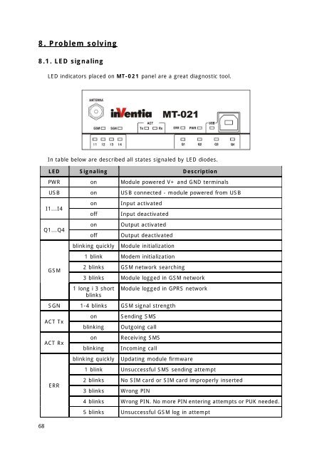
8.1. LED signaling<br />
LED indicators placed on <strong>MT</strong>-<strong>021</strong> panel are a great diagnostic tool.<br />
In table below are described all states signaled by LED diodes.<br />
LED Signaling Description<br />
PWR on <strong>Module</strong> powered V+ and GND terminals<br />
USB on USB connected - module powered from USB<br />
I1...I4<br />
Q1...Q4<br />
on<br />
off<br />
on<br />
off<br />
Input activated<br />
Input deactivated<br />
Output activated<br />
Output deactivated<br />
blinking quickly <strong>Module</strong> initialization<br />
1 blink Modem initialization<br />
GSM<br />
2 blinks GSM network searching<br />
3 blinks <strong>Module</strong> logged in GSM network<br />
1 long i 3 short<br />
blinks<br />
<strong>Module</strong> logged in GPRS network<br />
SGN 1-4 blinks GSM signal strength<br />
ACT Tx<br />
ACT Rx<br />
on<br />
blinking<br />
on<br />
blinking<br />
Sending SMS<br />
Outgoing call<br />
Receiving SMS<br />
Incoming call<br />
blinking quickly Updating module firmware<br />
1 blink Unsuccessful SMS sending attempt<br />
ERR<br />
2 blinks No SIM card or SIM card improperly inserted<br />
3 blinks Wrong PIN<br />
4 blinks Wrong PIN. No more PIN entering attempts or PUK needed.<br />
5 blinks Unsuccessful GSM log in attempt<br />
68