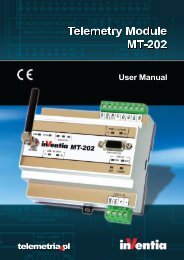
Telemetry Module MT-021 User Manual
Telemetry Module MT-021 User Manual
Telemetry Module MT-021 User Manual

You also want an ePaper? Increase the reach of your titles
YUMPU automatically turns print PDFs into web optimized ePapers that Google loves.
Any of binary inputs I1...I4 may operate as counter input. This requires a change in the<br />
operating mode of input, which is made during its configuration. The counter can count<br />
„up” or „down”, and the range can be freely defined in range of 1 to 2 147 483 647.<br />
Counting "up" means that the counter value is increased by 1 for each detected pulse<br />
and after reaching the value set as "counter length-1" is reset to "0". Counting "down"<br />
diminishes the counter value by 1 for each detected pulse and after reaching the value<br />
set as "counter length-1" is reset to "0" to resume the value of defined maximum.<br />
Crossing the value of counter length sets counter flag for respective input.<br />
These flags may be used in events table to trigger rules.<br />
3.7.2. Relay outputs<br />
<strong>MT</strong>-<strong>021</strong> telemetry module has 4 relay outputs Q1 ... Q4. Outputs can operate in one of<br />
two functional modes:<br />
monostable<br />
bistable<br />
The outputs operate independently and are isolated from each other.<br />
Outputs are control by writing value to the internal register (No. 8 - OUT_CTRL flag).<br />
This can be made remotely via SMS or CLIP.<br />
3.7.3. Analog inputs<br />
<strong>MT</strong>-<strong>021</strong> provides two analog inputs marked as AN1, AN2 which can operate in<br />
following modes:<br />
AN1:<br />
PT100 sensor temperature readout<br />
voltage input - 0…5V/0…10V<br />
current input - 4…20mA<br />
12