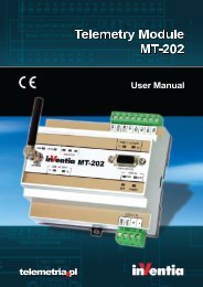
Telemetry Module MT-021 User Manual
Telemetry Module MT-021 User Manual
Telemetry Module MT-021 User Manual

Create successful ePaper yourself
Turn your PDF publications into a flip-book with our unique Google optimized e-Paper software.
NOTICE!<br />
Exceeding the range of accepted power supply voltage may cause<br />
faulty operation or damage to the module!<br />
3.3. SIM card<br />
<strong>MT</strong>-<strong>021</strong> telemetry module is equipped with standard miniature SIM card holder for<br />
connecting card to GSM modem.<br />
Proper placement of the SIM card is imperative for module's operation. The module<br />
accepts only SIM cards operating in low potential technology 3,3V.<br />
3.4. LED diodes<br />
LED indicators placed on <strong>MT</strong>-<strong>021</strong> front panel are convenient during module start up<br />
phase.<br />
The LED's have assigned following significance:<br />
PWR LED indicates module's activity,<br />
I1 ... I4 LED indicates state of binary inputs,<br />
Q1 ... Q4 LED indicates state of binary outputs,<br />
ERR LED indicates an error,<br />
GSM LED reflects current login to GSM network state,<br />
SGN LED reflects GSM signal strength,<br />
ACT (Tx i Rx) LEDs indicate GSM communication (TX - data transmission, RX - data<br />
reception),<br />
USB LED indicates USB port state.<br />
Detailed description can be found in LED signaling subchapter of Problem solving<br />
chapter.<br />
9