Telemetry Module MT-021 User Manual
Telemetry Module MT-021 User Manual
Telemetry Module MT-021 User Manual

You also want an ePaper? Increase the reach of your titles
YUMPU automatically turns print PDFs into web optimized ePapers that Google loves.
<strong>Telemetry</strong> <strong>Module</strong><br />
<strong>MT</strong>-<strong>021</strong><br />
<strong>User</strong> <strong>Manual</strong><br />
GSM/GPRS <strong>Telemetry</strong> <strong>Module</strong><br />
for monitoring and control<br />
Class 1 Telecommunications Terminal<br />
Equipment for GSM 850/900/1800/1900<br />
<strong>MT</strong>-<strong>021</strong><br />
INVENTIA Sp. z o.o<br />
v1.51
<strong>MT</strong>-<strong>021</strong><br />
© 2013 Inventia Ltd.<br />
Wszelkie prawa zastrzeżone. Żaden fragment niniejszego dokumentu nie może być powielany lub kopiowany<br />
w żadnej formie bez względu na stosowaną technologię – graficzną, elektroniczną lub mechaniczną, włączając<br />
fotokopiowanie i/lub zapis cyfrowy, również w systemach przechowywania i wyszukiwania dokumentów – bez<br />
pisemnej zgody Wydawcy.<br />
Nazwy produktów wymienionych w niniejszym dokumencie mogą być Znakami Towarowymi i/lub zastrzeżonymi<br />
Znakami Towarowymi należącymi do odpowiednich Właścicieli. Wydawca i Autor oświadczają, że nie roszczą<br />
do tych znaków towarowych żadnych praw.<br />
Pomimo, że niniejsze opracowanie tworzone było z zachowaniem wszelkiej należytej staranności, zarówno Wydawca<br />
jak i Autor nie ponoszą żadnej odpowiedzialności za błędy lub pominięcia w jego treści jak również za straty wynikłe<br />
z wykorzystania zawartej w niniejszym opracowaniu informacji lub ewentualnie towarzyszącego jej oprogramowania.<br />
W żadnym wypadku Wydawca lub Autor nie będą odpowiedzialni za utratę zysku lub inne straty, w tym handlowe,<br />
spowodowane lub rzekomo związane, bezpośrednio lub pośrednio, z niniejszym opracowaniem.<br />
All rights reserved. No parts of this work may be reproduced in any form or by any means - graphic, electronic, or<br />
mechanical, including photocopying, recording, taping, or information storage and retrieval systems - without the<br />
written permission of the publisher.<br />
Products that are referred to in this document may be either trademarks and/or registered trademarks of the<br />
respective owners. The publisher and the author make no claim to these trademarks.<br />
While every precaution has been taken in the preparation of this document, the publisher and the author assume no<br />
responsibility for errors or omissions, or for damages resulting from the use of information contained in this document<br />
or from the use of programs and source code that may accompany it. In no event shall the publisher and the author be<br />
liable for any loss of profit or any other commercial damage caused or alleged to have been caused directly or<br />
indirectly by this document.<br />
Publisher:<br />
Version:<br />
INVENTIA Sp. z o.o.<br />
ul. Kulczyńskiego 14<br />
02-777 Warszawa<br />
Tel: +48 22 545-32-00<br />
inventia@inventia.pl<br />
www.inventia.pl<br />
1.51<br />
Warsaw, Junuary 2013<br />
<strong>MT</strong>C Compatibility:<br />
1.51
INDEX<br />
1. MODULE'S DESTINATION ................................................................................................................ 7<br />
2. GSM REQUIREMENTS ...................................................................................................................... 7<br />
3. MODULE'S DESIGN ........................................................................................................................... 7<br />
3.1. MODULE'S TOPOGRAPHY .................................................................................................................................... 7<br />
3.2. POWER SUPPLY ................................................................................................................................................. 8<br />
3.3. SIM CARD ....................................................................................................................................................... 9<br />
3.4. LED DIODES ..................................................................................................................................................... 9<br />
3.5. ANTENNA ...................................................................................................................................................... 10<br />
3.6. HOUSING ...................................................................................................................................................... 10<br />
3.7. RESOURCES .................................................................................................................................................... 11<br />
3.7.1. Binary inputs ....................................................................................................................................... 11<br />
3.7.2. Relay outputs ...................................................................................................................................... 12<br />
3.7.3. Analog inputs...................................................................................................................................... 12<br />
3.7.4. Real time clock (RTC) .......................................................................................................................... 13<br />
3.7.5. USB port .............................................................................................................................................. 13<br />
3.7.6. Event logger ........................................................................................................................................ 14<br />
3.7.7. Timers ................................................................................................................................................. 14<br />
3.7.8. 1‐Wire inputs ...................................................................................................................................... 14<br />
4. STARTING THE MODULE ............................................................................................................... 16<br />
4.1. CONFIGURING <strong>MT</strong>‐<strong>021</strong> USING <strong>MT</strong>MANAGER ..................................................................................................... 17<br />
4.2. REMOTE CONFIGURATION VIA SMS .................................................................................................................... 21<br />
4.3. HOW DO I DISABLE A SIM PIN NUMBER .............................................................................................................. 22<br />
5. CONNECTIONS SCHEME................................................................................................................ 23<br />
5.1. POWER SUPPLY ............................................................................................................................................... 23<br />
5.2. BINARY INPUTS I1 ... I4 .................................................................................................................................... 24<br />
5.3. RELAY OUTPUTS Q1...Q4 ................................................................................................................................. 25<br />
5.4. ANALOG INPUTS AN1, AN2 ............................................................................................................................. 25<br />
5.5. 1‐WIRE INPUTS .............................................................................................................................................. 27<br />
6. CONFIGURATION ............................................................................................................................ 28<br />
6.1. GENERAL INFORMATION ................................................................................................................................... 28<br />
6.2. PARAMETER GROUPS ....................................................................................................................................... 28<br />
6.2.1. Header ................................................................................................................................................ 29<br />
6.2.1.1. <strong>Module</strong> name ................................................................................................................................................ 29<br />
6.2.1.2. <strong>Module</strong> type .................................................................................................................................................. 29<br />
6.2.1.3. <strong>Module</strong> serial number................................................................................................................................... 29<br />
6.2.1.4. IMEI number ................................................................................................................................................. 29<br />
6.2.1.5. SIM card number .......................................................................................................................................... 29<br />
6.2.1.6. Modem's firmware version ........................................................................................................................... 30<br />
6.2.1.7. Firmware version .......................................................................................................................................... 30<br />
6.2.1.8. Configuration file version .............................................................................................................................. 30<br />
6.2.1.9. Configuration identifier................................................................................................................................. 30<br />
6.2.1.10. Last configuration date ............................................................................................................................... 30<br />
6.2.1.11. Last reading time ........................................................................................................................................ 31<br />
6.2.2. General ............................................................................................................................................... 31<br />
6.2.2.1. SIM card PIN number .................................................................................................................................... 31<br />
1
2<br />
6.2.2.2. Configuration password ................................................................................................................................ 31<br />
6.2.2.3. Use of GPRS .................................................................................................................................................. 32<br />
6.2.3. SMS ..................................................................................................................................................... 32<br />
6.2.3.1. Daily SMS limit .............................................................................................................................................. 32<br />
6.2.3.2. Roaming for SMS .......................................................................................................................................... 32<br />
6.2.3.3. Number of SMS sending retries .................................................................................................................... 33<br />
6.2.3.4. Answer for blank SMS ................................................................................................................................... 33<br />
6.2.3.5. SMS limit exceed information text ................................................................................................................ 33<br />
6.2.3.5.1. Phone number of info recipient ............................................................................................................ 33<br />
6.2.3.5.2. SMS limit exceed information ............................................................................................................... 34<br />
6.2.3.6. Formats ......................................................................................................................................................... 34<br />
6.2.3.6.1. Date format ........................................................................................................................................... 34<br />
6.2.3.6.2. Time format .......................................................................................................................................... 34<br />
6.2.3.6.3. General format 1 ................................................................................................................................... 35<br />
6.2.3.6.4. General format 2 ................................................................................................................................... 35<br />
6.2.3.7. Symbolic names ............................................................................................................................................ 35<br />
6.2.3.7.1. Number of symbolic names .................................................................................................................. 35<br />
6.2.3.7.2. Symbolic name ...................................................................................................................................... 36<br />
6.2.3.7.3. Space ..................................................................................................................................................... 36<br />
6.2.3.7.4. Register/bit number .............................................................................................................................. 36<br />
6.2.3.8. Macros .......................................................................................................................................................... 36<br />
6.2.3.8.1. Number of macros ................................................................................................................................ 36<br />
6.2.3.8.2. Macro name .......................................................................................................................................... 37<br />
6.2.3.8.3. Macro's content .................................................................................................................................... 37<br />
6.2.4. GPRS ................................................................................................................................................... 37<br />
6.2.4.1. APN name ..................................................................................................................................................... 37<br />
6.2.4.2. APN user name ............................................................................................................................................. 37<br />
6.2.4.3. APN password ............................................................................................................................................... 37<br />
6.2.4.4. <strong>Module</strong> IP ...................................................................................................................................................... 38<br />
6.2.4.5. GPRS login retry interval [s] .......................................................................................................................... 38<br />
6.2.4.6. GPRS testing address (ping) .......................................................................................................................... 38<br />
6.2.4.7. Idle time [s] ................................................................................................................................................... 38<br />
6.2.5. Authorized numbers ........................................................................................................................... 39<br />
6.2.5.1. Number of phone numbers .......................................................................................................................... 39<br />
6.2.5.2. Update phone numbers from SIM card ........................................................................................................ 39<br />
6.2.5.3. Phone number from SIM card always authorized ......................................................................................... 39<br />
6.2.5.4. Phone ............................................................................................................................................................ 40<br />
6.2.6. Resources ............................................................................................................................................ 40<br />
6.2.6.1. Terminals ...................................................................................................................................................... 41<br />
6.2.6.1.1. Inputs I1 ... I4......................................................................................................................................... 41<br />
6.2.6.1.1.1. Name ............................................................................................................................................. 41<br />
6.2.6.1.1.2. Input type ...................................................................................................................................... 41<br />
6.2.6.1.1.2.1. Counter input ........................................................................................................................ 41<br />
6.2.6.1.1.2.1.1. Counting direction ......................................................................................................... 41<br />
6.2.6.1.1.2.1.2. Counting range (32bits) ................................................................................................. 42<br />
6.2.6.1.1.2.1.3. Triggering slope ............................................................................................................. 42<br />
6.2.6.1.1.3. Filtering constant [s] ...................................................................................................................... 42<br />
6.2.6.1.2. Outputs Q1 ... Q4 .................................................................................................................................. 42<br />
6.2.6.1.2.1. Name ............................................................................................................................................. 43<br />
6.2.6.1.2.2. Output mode ................................................................................................................................. 43<br />
6.2.6.1.2.3. Pulse duration [s] .......................................................................................................................... 43<br />
6.2.6.1.2.4. On event ........................................................................................................................................ 43<br />
6.2.6.1.2.5. Off event ....................................................................................................................................... 43<br />
6.2.6.1.3. Analog inputs AN1...AN2 ....................................................................................................................... 44<br />
6.2.6.1.3.1. Name ............................................................................................................................................. 44
6.2.6.1.3.2. Input type ...................................................................................................................................... 44<br />
6.2.6.1.3.3. Filtering constant [s] ...................................................................................................................... 44<br />
6.2.6.1.3.4. Signal range ................................................................................................................................... 44<br />
6.2.6.1.3.5. Low reference ‐ internal units ....................................................................................................... 45<br />
6.2.6.1.3.6. High reference ‐ internal units ...................................................................................................... 45<br />
6.2.6.1.3.7. Low reference ‐ engineering units ................................................................................................. 45<br />
6.2.6.1.3.8. High reference ‐ engineering units ................................................................................................ 45<br />
6.2.6.1.3.9. Alarm HiHi ‐ engineering units ...................................................................................................... 46<br />
6.2.6.1.3.10. Alarm Hi ‐ engineering units ........................................................................................................ 46<br />
6.2.6.1.3.11. Alarm Lo ‐ engineering units ....................................................................................................... 46<br />
6.2.6.1.3.12. Alarm LoLo ‐ engineering units .................................................................................................... 46<br />
6.2.6.1.3.13. Alarm hysteresis ‐ engineering units ........................................................................................... 46<br />
6.2.6.1.3.14. Deadband ‐ engineering units ..................................................................................................... 47<br />
6.2.6.1.4. Inputs 1‐WIRE1, 1‐WIRE2 ...................................................................................................................... 47<br />
6.2.6.1.4.1. Name ............................................................................................................................................. 47<br />
6.2.6.1.4.2. Input type ...................................................................................................................................... 47<br />
6.2.6.1.4.2.1. Temperature measurement .................................................................................................. 47<br />
6.2.6.1.4.2.1.1. Alarm HiHi ...................................................................................................................... 48<br />
6.2.6.1.4.2.1.2. Alarm Hi ......................................................................................................................... 48<br />
6.2.6.1.4.2.1.3. Alarm Lo ......................................................................................................................... 48<br />
6.2.6.1.4.2.1.4. Alarm LoLo ..................................................................................................................... 48<br />
6.2.6.1.4.2.1.5. Alarm hysteresis ............................................................................................................ 48<br />
6.2.6.1.4.2.1.6. Deadband ...................................................................................................................... 49<br />
6.2.6.2. Synchronous timers TMR1...TMR4 ............................................................................................................... 49<br />
6.2.6.2.1. Active .................................................................................................................................................... 49<br />
6.2.6.2.1.1. Start [HH:MM] ............................................................................................................................... 49<br />
6.2.6.2.1.2. Period ............................................................................................................................................ 49<br />
6.2.6.2.1.3. Days of week ................................................................................................................................. 50<br />
6.2.6.2.1.4. Days of month ............................................................................................................................... 50<br />
6.2.6.3. State logging ................................................................................................................................................. 50<br />
6.2.6.3.1. Start [HH:MM] ...................................................................................................................................... 50<br />
6.2.6.3.2. Period .................................................................................................................................................... 50<br />
6.2.6.3.3. Logged information ............................................................................................................................... 51<br />
6.2.7. Events ................................................................................................................................................. 51<br />
6.2.7.1. Number of events ......................................................................................................................................... 51<br />
6.2.7.2. Name ............................................................................................................................................................ 51<br />
6.2.7.3. Trigger source (binary inputs) ....................................................................................................................... 51<br />
6.2.7.3.1. Trigger input .......................................................................................................................................... 52<br />
6.2.7.3.2. Trigger condition ................................................................................................................................... 52<br />
6.2.7.4. Trigger source (analog inputs) ...................................................................................................................... 52<br />
6.2.7.4.1. Trigger input .......................................................................................................................................... 53<br />
6.2.7.4.2. Trigger condition ................................................................................................................................... 53<br />
6.2.7.5. Trigger source (inputs 1‐WIRE) ..................................................................................................................... 53<br />
6.2.7.5.1. Trigger input .......................................................................................................................................... 53<br />
6.2.7.5.2. Trigger condition ................................................................................................................................... 54<br />
6.2.7.6. Trigger source (Clocks) .................................................................................................................................. 54<br />
6.2.7.6.1. Triggering clock ..................................................................................................................................... 54<br />
6.2.7.7. Trigger source (Flags) .................................................................................................................................... 55<br />
6.2.7.7.1. Triggering flag ....................................................................................................................................... 55<br />
6.2.7.8. Trigger source (Counters) ............................................................................................................................. 55<br />
6.2.7.8.1. Triggering counter ................................................................................................................................. 56<br />
6.2.7.9. Trigger source (Connections) ........................................................................................................................ 56<br />
6.2.7.9.1. Connection from any authorized .......................................................................................................... 56<br />
6.2.7.9.1.1. Dial‐in from number ...................................................................................................................... 57<br />
6.2.8. Rules ................................................................................................................................................... 57<br />
3
6.2.8.1. Massage sending ........................................................................................................................................... 57<br />
6.2.8.1.1. Number of message sending rules ........................................................................................................ 57<br />
6.2.8.1.2. Sender e‐mail address ........................................................................................................................... 57<br />
6.2.8.1.3. S<strong>MT</strong>P server name ................................................................................................................................ 58<br />
6.2.8.1.4. S<strong>MT</strong>P server port .................................................................................................................................. 58<br />
6.2.8.1.5. S<strong>MT</strong>P authentication ............................................................................................................................. 58<br />
6.2.8.1.6. S<strong>MT</strong>P user name ................................................................................................................................... 58<br />
6.2.8.1.7. S<strong>MT</strong>P password ..................................................................................................................................... 58<br />
6.2.8.1.8. Message sending rules 1...32 ................................................................................................................ 59<br />
6.2.8.1.8.1. Triggering event ............................................................................................................................ 59<br />
6.2.8.1.8.2. Transmission type ......................................................................................................................... 59<br />
6.2.8.1.8.3. Recipient number .......................................................................................................................... 59<br />
6.2.8.1.8.4. Receiver e‐mail address ................................................................................................................ 60<br />
6.2.8.1.8.5. E‐mail title ..................................................................................................................................... 60<br />
6.2.8.1.8.6. Message text ................................................................................................................................. 60<br />
6.2.8.2. CLIP calls ....................................................................................................................................................... 60<br />
6.2.8.2.1. Number of CLIP calls rules ..................................................................................................................... 61<br />
6.2.8.2.2. CLIP call rules 1...16 ............................................................................................................................... 61<br />
6.2.8.2.2.1. Triggering event ............................................................................................................................ 61<br />
6.2.8.2.2.2. Recipient number .......................................................................................................................... 61<br />
6.2.8.3. E‐mail sending ............................................................................................................................................... 61<br />
6.2.8.3.1. Number of e‐mail sending rules ............................................................................................................ 61<br />
6.2.8.3.2. Sender e‐mail address ........................................................................................................................... 62<br />
6.2.8.3.3. S<strong>MT</strong>P server name ................................................................................................................................ 62<br />
6.2.8.3.4. S<strong>MT</strong>P server port .................................................................................................................................. 62<br />
6.2.8.3.5. S<strong>MT</strong>P authentication ............................................................................................................................. 62<br />
6.2.8.3.6. S<strong>MT</strong>P user name ................................................................................................................................... 63<br />
6.2.8.3.7. S<strong>MT</strong>P password ..................................................................................................................................... 63<br />
6.2.8.3.8. E‐mail sending rules 1...16 .................................................................................................................... 63<br />
6.2.8.3.8.1. Triggering event ............................................................................................................................ 63<br />
6.2.8.3.8.2. Receiver e‐mail address ................................................................................................................ 63<br />
6.2.8.3.8.3. E‐mail title ..................................................................................................................................... 64<br />
6.2.8.3.8.4. E‐mail text ..................................................................................................................................... 64<br />
6.3. CONFIGURATION WRITING ................................................................................................................................ 64<br />
6.4. VERIFICATION OF CONFIGURATION ..................................................................................................................... 64<br />
7. TECHNICAL DATA ........................................................................................................................... 65<br />
7.1. GENERAL ....................................................................................................................................................... 65<br />
7.2. GSM MODEM ............................................................................................................................................... 65<br />
7.3. POWER SUPPLY ............................................................................................................................................... 65<br />
7.4. BINARY INPUTS I1....I4 .................................................................................................................................... 66<br />
7.5. RELAY OUTPUTS Q1...Q4 ................................................................................................................................. 66<br />
7.6. ANALOGUE INPUTS AN1, AN2 .......................................................................................................................... 66<br />
7.7. DRAWINGS AND DIMENSIONS (ALL DIMENSIONS IN MILLIMETERS) ............................................................................ 67<br />
8. PROBLEM SOLVING ....................................................................................................................... 68<br />
8.1. LED SIGNALING .............................................................................................................................................. 68<br />
8.2. UNBLOCKING OF SIM CARD .............................................................................................................................. 69<br />
9. SAFETY INFORMATION .................................................................................................................. 69<br />
9.1. WORKING ENVIRONMENT ................................................................................................................................. 69<br />
9.2. ELECTRONIC EQUIPMENT .................................................................................................................................. 69<br />
9.2.1. Heart pacemakers .............................................................................................................................. 69<br />
4
9.2.2. Hearing aids........................................................................................................................................ 69<br />
9.2.3. Other medical equipment ................................................................................................................... 69<br />
9.2.4. RF Marked equipment ........................................................................................................................ 70<br />
9.3. EXPLOSIVE ENVIRONMENT ................................................................................................................................ 70<br />
10. APPENDICES ................................................................................................................................. 70<br />
10.1. REGISTER OF CHANGES ................................................................................................................................... 70<br />
10.2. MODULE CONFIGURATION VIA SMS ................................................................................................................. 71<br />
10.3. SYNTAX FOR READING AND WRITING DATA IN SMS MODE ..................................................................................... 79<br />
10.4. MEMORY MAP ............................................................................................................................................. 85<br />
10.4.1. Analog inputs address space ............................................................................................................ 86<br />
10.4.2. Internal registers address space ....................................................................................................... 90<br />
10.5. FLAGS ......................................................................................................................................................... 91<br />
5
1. <strong>Module</strong>'s destination<br />
<strong>Telemetry</strong> <strong>Module</strong> <strong>MT</strong>-<strong>021</strong> with built-in GSM modem is a device dedicated for remote<br />
monitoring, diagnostics and control of objects via short text messages (SMS), CLIP calls<br />
or e-mail. Configurable messages send from device with static (text) or dynamic (text<br />
and measured values) content are a convenient way of passing important information to<br />
the monitoring center, or directly to the defined phone numbers. SMS messages sending<br />
can be triggered by change of binary input state, reaching alarm thresholds, marker<br />
state change, counters and clocks. Industrial design, practical set of I/O resources, easy<br />
to use software tools as well as the ability to configure the module from remote via SMS<br />
commands are significant advantages of <strong>MT</strong>-<strong>021</strong> in the wireless telemetry systems.<br />
Direct connection of temperature sensors lowers the cost of building system. 1-Wire<br />
inputs can be used for reading typical Dallas pellets for the purpose of identification and<br />
authentication. The module can work with humidity sensors, water level sensor,<br />
pressure transducers, flow sensors, smoke, gas, motion, shock and noise detectors, etc.<br />
Typical applications:<br />
• Alarm systems • Access control • Preventive diagnostic • Remote meter<br />
reading (AMR) • Remote control of various devices by CLIP call or SMS (gates,<br />
pumps, heating, lighting, etc.)<br />
2. GSM requirements<br />
For proper operation of the module a SIM card provided by a GSM operator with<br />
SMS/CLIP option enabled is essential. Enabled GPRS communication allows device to<br />
send e-mails.<br />
A paramount condition for operation is securing the adequate GSM signal level in the<br />
place where module's antenna is placed. Using the module in places where there is no<br />
adequate signal level may cause breaks in transmission and thereby data loss along with<br />
generating excessive transmission costs.<br />
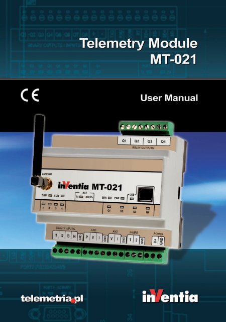
3. <strong>Module</strong>'s design<br />
3.1. <strong>Module</strong>'s topography<br />
7
3.2. Power supply<br />
<strong>MT</strong>-<strong>021</strong> may be powered by 9...30 V (DC).<br />
8
NOTICE!<br />
Exceeding the range of accepted power supply voltage may cause<br />
faulty operation or damage to the module!<br />
3.3. SIM card<br />
<strong>MT</strong>-<strong>021</strong> telemetry module is equipped with standard miniature SIM card holder for<br />
connecting card to GSM modem.<br />
Proper placement of the SIM card is imperative for module's operation. The module<br />
accepts only SIM cards operating in low potential technology 3,3V.<br />
3.4. LED diodes<br />
LED indicators placed on <strong>MT</strong>-<strong>021</strong> front panel are convenient during module start up<br />
phase.<br />
The LED's have assigned following significance:<br />
PWR LED indicates module's activity,<br />
I1 ... I4 LED indicates state of binary inputs,<br />
Q1 ... Q4 LED indicates state of binary outputs,<br />
ERR LED indicates an error,<br />
GSM LED reflects current login to GSM network state,<br />
SGN LED reflects GSM signal strength,<br />
ACT (Tx i Rx) LEDs indicate GSM communication (TX - data transmission, RX - data<br />
reception),<br />
USB LED indicates USB port state.<br />
Detailed description can be found in LED signaling subchapter of Problem solving<br />
chapter.<br />
9
3.5. Antenna<br />
Attachment of antenna is essential for proper operation of <strong>MT</strong>-101 telemetry module.<br />
SMA socket is placed on module's front panel. The attached antenna has to secure<br />
appropriate radio signal level enabling login to GSM network.<br />
The type and placement of antenna has significant influence on module's<br />
sender/receiver circuits. GSM signal level is reflected by SGN led on module's front<br />
panel. Please use a directional antenna system when GSM signal level is not sufficient.<br />
Refer chapter Problem solving/LED signaling.<br />
3.6. Housing<br />
<strong>MT</strong>-<strong>021</strong> module is encapsulated in standard housing made of plastic compliant with<br />
safety requirements and protecting the module in standard operating environment.<br />
The applied solution complies with standard industrial requirements for DIN rail<br />
mounting.<br />
10
3.7. Resources<br />
<strong>MT</strong>-<strong>021</strong> module's resources:<br />
I1...I4 - binary inputs 4 Optoisolated binary inputs<br />
Q1...Q4 - Relay outputs 4<br />
Relay outputs can operate in one of<br />
two functional modes:<br />
monostable<br />
bistable<br />
CNT - Counters 0 (max. 4) Each input can work as a counter input<br />
AN1, AN2 - Analog inputs 2<br />
1-Wire - Inputs 2<br />
PT100<br />
NTC<br />
0..10V/0..5V<br />
4-20mA<br />
Standard Dallas I-Button,<br />
Temperature measurement<br />
USB Port 1 Standard RS232 - configuration<br />
3.7.1. Binary inputs<br />
<strong>MT</strong>-<strong>021</strong> module is equipped with 4 optoisolated binary inputs marked as I1...I4. They<br />
may work only in positive logic. All binary inputs have same reference - module's<br />
electrical ground - negative pole of the power supply connected to GND pin.<br />
The change of the input signal sets the alarm flag, connected with the corresponding<br />
binary input respectively as Bi 0->1, Bi 1->0 or Bi 0->1|Bi 1->0.<br />
11
Any of binary inputs I1...I4 may operate as counter input. This requires a change in the<br />
operating mode of input, which is made during its configuration. The counter can count<br />
„up” or „down”, and the range can be freely defined in range of 1 to 2 147 483 647.<br />
Counting "up" means that the counter value is increased by 1 for each detected pulse<br />
and after reaching the value set as "counter length-1" is reset to "0". Counting "down"<br />
diminishes the counter value by 1 for each detected pulse and after reaching the value<br />
set as "counter length-1" is reset to "0" to resume the value of defined maximum.<br />
Crossing the value of counter length sets counter flag for respective input.<br />
These flags may be used in events table to trigger rules.<br />
3.7.2. Relay outputs<br />
<strong>MT</strong>-<strong>021</strong> telemetry module has 4 relay outputs Q1 ... Q4. Outputs can operate in one of<br />
two functional modes:<br />
monostable<br />
bistable<br />
The outputs operate independently and are isolated from each other.<br />
Outputs are control by writing value to the internal register (No. 8 - OUT_CTRL flag).<br />
This can be made remotely via SMS or CLIP.<br />
3.7.3. Analog inputs<br />
<strong>MT</strong>-<strong>021</strong> provides two analog inputs marked as AN1, AN2 which can operate in<br />
following modes:<br />
AN1:<br />
PT100 sensor temperature readout<br />
voltage input - 0…5V/0…10V<br />
current input - 4…20mA<br />
12
AN1:<br />
NTC sensor temperature readout<br />
voltage input - 0…5V/0…10V<br />
current input - 4…20mA<br />
3.7.4. Real time clock (RTC)<br />
<strong>MT</strong>-<strong>021</strong> <strong>Module</strong> is equipped with astronomical time clock (RTC).<br />
The clock is a base for defining working cycles of module, timers and time stamps for<br />
measurement results recorded in registers. Imprecise clock setting results in faulty time<br />
stamping and subsequent loss of vital information. For that reason, it is recommended<br />
to set the clock to UTC time instead of the local time zone of the module's placement.<br />
CAUTION!<br />
The clock setting has to be repeated if the module was turned off<br />
for long time.<br />
Setting the time is described in configuring mode documentation for the <strong>MT</strong>Manager<br />
program. There is also a method for setting the RTC remotely using SMS configuration<br />
commands described in chapter Starting the module/Remote configuration via SMS.<br />
3.7.5. USB port<br />
<strong>MT</strong>-<strong>021</strong> module is equipped with one USB port.<br />
This port is intended for the local configuration of the module's parameters and readout<br />
event logger. The port should be connected to an external PC computer with the<br />
configuration program running (<strong>MT</strong>Manager) or software for reading event logger (<strong>MT</strong><br />
Log Reader).<br />
13
3.7.6. Event logger<br />
<strong>MT</strong>-<strong>021</strong> automatically registers events like analog inputs measurement, time interval<br />
being counted by timer, GSM logon, making an outgoing call, one of analog values<br />
exceeding an alarm thresholds value, module power on and other. Logger can store up<br />
to 48000 records. This allows to reconstruct the history of module operations.<br />
Logger records can be read via USB using <strong>MT</strong> Log Reader application.<br />
3.7.7. Timers<br />
<strong>MT</strong>-<strong>021</strong> provides four synchronous timers TMR1…TMR4 that enable cyclical time<br />
measuring from 1 min to 1 month with synchronization with module z RTC clock. Timers<br />
can be used for triggering various actions like establishing clip calls, setting binary<br />
outputs and other.<br />
3.7.8. 1-Wire inputs<br />
<strong>Telemetry</strong> <strong>Module</strong> <strong>MT</strong>-<strong>021</strong> is equipped with two 1-Wire inputs for connection sensors<br />
using this interface for transmission of measured temperature value and Dallas I-button<br />
used for identification.<br />
There is possibility of creating individual 1-Wire solutions to suit special application<br />
needs. For more information please contact your local distributor.<br />
14
4. Starting the module<br />
Starting <strong>MT</strong>-<strong>021</strong> module requires few basic activities.<br />
There are two methods of configuring module:<br />
locally - using <strong>MT</strong>Manager<br />
remotely - via SMS<br />
Using one method does not exclude using of the second as the can be used<br />
interchangeably.<br />
Starting <strong>MT</strong>-<strong>021</strong><br />
1. Connect GSM antenna,<br />
2. Install SIM card. If plan to make first configuration of module via SMS turn off PIN<br />
code request,<br />
Notice!<br />
The details of the procedure unlock the SIM card is described<br />
in the chapter How do I disable a SIM PIN number.<br />
3. Connect power to module ('POWER' terminal block; 9...30 VDC).<br />
Correct power connection is signaled by PWR LED (green light). After connecting power<br />
the module starts process of registration in the GSM network. If you use a SIM card with<br />
PIN code request option turned off, module should log on to the GSM network.<br />
Successful GSM network logon is indicated by three blinks of GSM LED and signal<br />
strength presented on SGN LEDs.<br />
16
In next steps you will see how to create basic configuration, which can be described by<br />
following points:<br />
Entering PIN code,<br />
Adding telephone number to authorized phone list,<br />
Defining event for binary input I1 when it is changing its state from 0 to 1 (rising<br />
edge),<br />
Defining SMS sending rule which will send SMS that reads “ALARM” to a predefined<br />
phone number when previously configured event is triggered,<br />
Setting RTC clock of the device.<br />
4.1. Configuring <strong>MT</strong>-<strong>021</strong> using <strong>MT</strong>Manager<br />
Install <strong>MT</strong>Manager on your PC from CD provided with module.<br />
When installed with default setting <strong>MT</strong>Manager creates shortcuts on Desktop and in<br />
Start menu.<br />
Please proceed to next step.<br />
Start <strong>MT</strong>Manager by double-click on shortcut icon:<br />
In newly created <strong>MT</strong>Manager project add new module using main menu option<br />
General->New-><strong>Module</strong>.<br />
17
Choose <strong>MT</strong>-<strong>021</strong> as type, type module name (e.g. ST_1) in name field and select<br />
firmware version (firmware version is marked on the box).<br />
In the next step set parameters essential for establishing GSM connection:<br />
SIM card PIN number (required if PIN code request is on<br />
Configuration password to protect module from unauthorized access.<br />
Open Authorized numbers -> Phone and add to the list new telephone number which will<br />
be receiving SMS messages from device (e.g. +48111222333).<br />
18
Create Event EVT1 (in this example event will be triggered by binary input I1 when<br />
changing it will change logical state 0->1).<br />
As last step of configuration please set SMS sending rule 1. Choose EVT1 as Triggering<br />
event, type ALARM in SMS text. NUM1 corresponds to telephone number added in<br />
previous step.<br />
19
To write into module configuration prepared in previous steps connect <strong>MT</strong>-<strong>021</strong> with PC<br />
using USB cable provided with module. Proper USB connection is signaled by USB LED.<br />
Operating system should automatically install driver for <strong>MT</strong>-<strong>021</strong> - it will be seen in<br />
Device Manager as additional COM port called Silicon Labs CP210x USB to UART<br />
Bridge (COMX), where X is COM port number.<br />
Please open Environment in <strong>MT</strong>Manager (General->Environment), set correct COM<br />
port in USB cable option and press Write to save setting.<br />
20
Next press Connect button (Transmission->Connect) then Write button<br />
(Transmission->Write).<br />
At the end synchronize device RT using Set time button (Configuration->Set time).<br />
Now setting binary input in high logical state, e.g. by connecting V+ cable with terminal<br />
I1 and power GND with binary inputs GND, will result in sending SMS that reads ‘ALARM<br />
‘ to +48111222333.<br />
4.2. Remote configuration via SMS<br />
Configuration described in chapter Configurating <strong>MT</strong>-<strong>021</strong> using <strong>MT</strong>Manager can be also<br />
written to module using SMS commands. Those commands, their default values and<br />
allowed value ranges are described in chapter Appendices/<strong>Module</strong> configuration via<br />
SMS. Below you can find sample configuration SMS:<br />
21
&#SPIN="2323"#CONF_PSW="PASS"#SMSN_1="+48111222333"#EVNO=1<br />
#EV_TRIG_1=2#EV_FLAG_1=0#EV_EDGE_1=1#TRNO=1#TR_TRIG_1=1<br />
#TR_TCH_1=1#TR_T_1="ALARM"#TR_N_1=1<br />
That SMS sets:<br />
SIM card PIN number (2323)<br />
Configuration password (PASS)<br />
First telephone on Authorized->Phone list (+48111222333)<br />
Event EVT1 triggered when binary input I1 changes its logical state 0->1<br />
SMS sending rule 1 which will send SMS saying ALARM to previously defined telephone<br />
number each time event EVT1 is triggered.<br />
As an answer to this SMS module will send back the same text preceding it with '>' sign.<br />
After first configuration it is good to adjust module RTC. SMS below sets time to last<br />
second of 2010:<br />
&PASS#CRTC="2010-12-31 23:59:59"<br />
SMS begins new password set by previous configuration SMS preceded by '&' sign.<br />
First configuration can be done from any phone number. Any following SMS<br />
configuration commands will be accepted only from numbers placed on Authorized list.<br />
Therefore it is vital to enter at least one phone number to that list during first<br />
configuration. Maximum length of SMS configuration command should not exceed 160<br />
signs.<br />
Now setting binary input in high logical state, e.g. by connecting V+ cable with terminal<br />
I1 and power GND with binary inputs GND, will result in sending SMS that reads ‘ALARM<br />
‘ to +48111222333.<br />
4.3. How do I disable a SIM PIN number<br />
The procedure for setting the SIM mode to allow its use without requiring a PIN (e.g.<br />
Nokia, model 6210):<br />
Place the SIM card into the appropriate slot on the phone.<br />
Turn on the phone, and enter the correct PIN number for your SIM card.<br />
From the available commands, select Menu\Settings\Security Settings.<br />
Choose menu PIN code request then press Select, you will be prompted for a PIN<br />
number.<br />
Then select OFF response to a question PIN code request<br />
At the end appears a message PIN code request is not active.<br />
22
5. Connections scheme<br />
The chapter shows standard configurations securing proper operation of <strong>MT</strong>-<strong>021</strong><br />
module's integral inputs/outputs in all available operating modes.<br />
5.1. Power supply<br />
<strong>MT</strong>-<strong>021</strong> module can be powered from any DC power source providing voltage within<br />
the range 9-30 VDC.<br />
Notice!<br />
Exceeding the range of power supply may cause faulty<br />
operation or damage the module!<br />
Notice!<br />
Supply cables length < 10m. Signal cables length < 30m.<br />
For longer cables it is recommended to use external<br />
overvoltage protection.<br />
23
5.2. Binary inputs I1 ... I4<br />
Internal optoisolated binary inputs marked as I1...I4 may work only in positive logic. All<br />
binary inputs have same reference - module's electrical ground - negative pole of the<br />
power supply connected to GND pin.<br />
Connection scheme:<br />
Notice!<br />
Supply cables length < 10m.<br />
Signal cables length < 30m.<br />
For longer cables it is recommended to use external<br />
overvoltage protection.<br />
24
5.3. Relay outputs Q1...Q4<br />
<strong>Telemetry</strong> module has 4 normally open (NO) relay outputs marked as Q1 ... Q4.<br />
The outputs operate independently and are isolated from each other.<br />
Connection scheme:<br />
Notice!<br />
Maximum voltage between contacts is 230V AC<br />
Maximum switching current is 6A.<br />
5.4. Analog inputs AN1, AN2<br />
Analog inputs AN1 and AN2 can be used for measuring temperature using Pt-100 and<br />
NTC sensors or collecting measurements via current (4-20mA) or voltage signal<br />
(0-5V/0-10V). Mode of operation is user-configurable. Below are shown proper<br />
connection schematics:<br />
25
Pt-100 - 2 wire (AN1 only)<br />
Pt-100 - 3 wire (AN1 only)<br />
NTC (AN2 only)<br />
Voltage output sensor<br />
26
Current output sensor<br />
5.5. 1-Wire inputs<br />
For the 1-Wire communication is used one line for data and GND line. The <strong>MT</strong>-<strong>021</strong> has<br />
two 1-Wire bus inputs marked as 1 and 2 with a common reference point (GND).<br />
Connection scheme:<br />
27
6. Configuration<br />
6.1. General information<br />
The configuration of <strong>MT</strong>-<strong>021</strong> module, as is the case for other modules in the <strong>MT</strong> series,<br />
is carried out using the <strong>MT</strong>M (<strong>MT</strong> Manager) program portal, delivered free of charge to<br />
users of our telemetry solutions.<br />
The portal is a specialized environment providing full control of the entire telemetry<br />
system regardless of the system's size. The possibility of dividing hardware resources<br />
into Projects and Folders facilitates efficient management of very complex telemetry<br />
systems.<br />
After adding a new module to the environment and selecting it, all module parameters<br />
are available for editing. Detailed description of functions and their applications are to<br />
be found in <strong>MT</strong>M user manual.<br />
Each of the configuration parameters is also possible to set by SMS. SMS schemes have<br />
been presented in Chapter Appendices/<strong>Module</strong> configuration via SMS<br />
NOTICE!<br />
Availability of different functions and parameters depends on module's<br />
firmware version and the settings of parameters they may be dependent on.<br />
6.2. Parameter groups<br />
For clarity and ease of use, the operating parameters of <strong>MT</strong>-<strong>021</strong> module are divided<br />
into logically or functionally connected groups in the following order:<br />
Header group - contains unmodifiable parameters describing the module, its firmware<br />
and configuration.<br />
General group - contains basic parameters defining module's operating mode<br />
SMS group - contains parameters for SMS services handling<br />
GPRS group - contains parameters for GPRS logging<br />
Authorized numbers group - contains lists of phone numbers of other terminals<br />
authorized for communication with configured module.<br />
Resources group - defines parameters for hardware and software resources related to<br />
reading and processing measurement data.<br />
Events group - contains list of defined events (e.g. binary input state change), used to<br />
trigger module's actions (e.g.: sending SMS or trigger CLIP)<br />
Rules group - contains lists of transmission tasks to be carried out upon occurrence of<br />
activating criteria<br />
28
6.2.1. Header<br />
Header of parameter structure describes <strong>MT</strong>-<strong>021</strong> telemetry module. It holds basic<br />
information unique to the module, the configuration contained by module and<br />
configuration file version. Information displayed is not user editable and solely used for<br />
verification and information purpose.<br />
6.2.1.1. <strong>Module</strong> name<br />
Function<br />
Data type<br />
Range<br />
Default value<br />
Comments<br />
- displays name assigned to module during configuration<br />
- text<br />
- n/a, read-only parameter<br />
- New module<br />
- n/a<br />
6.2.1.2. <strong>Module</strong> type<br />
Function<br />
Data type<br />
Range<br />
Default value<br />
Comments<br />
- displays the type of configured telemetry module<br />
- text<br />
- n/a, read-only parameter<br />
- <strong>MT</strong>-<strong>021</strong><br />
- n/a<br />
6.2.1.3. <strong>Module</strong> serial number<br />
Function<br />
Data type<br />
Range<br />
Default value<br />
Comments<br />
- displays serial number configured telemetry module<br />
- text<br />
- n/a, Read-only parameter<br />
- n/a<br />
- this field displays module serial number assigned during<br />
manufacturing. This number is static and unique identifier of<br />
the unit.<br />
6.2.1.4. IMEI number<br />
Function<br />
Data type<br />
Range<br />
Comments<br />
- displays GSM modem's IMEI number<br />
- text<br />
- n/a, read-only parameter<br />
- n/a<br />
6.2.1.5. SIM card number<br />
Function<br />
Data type<br />
Range<br />
Comments<br />
- displays SIM card's serial number<br />
- Number<br />
- n/a, read-only parameter<br />
- n/a<br />
29
6.2.1.6. Modem's firmware version<br />
Function<br />
Data type<br />
Range<br />
Default value<br />
Comments<br />
- displays GSM modem's firmware version<br />
- text<br />
- n/a, read-only parameter<br />
- n/a<br />
- the field updates automatically after downloading the firmware.<br />
6.2.1.7. Firmware version<br />
Function<br />
- displays the identifier of current firmware version<br />
Data type<br />
- text<br />
Range<br />
- n/a, read-only parameter<br />
Default value - e.g. 1.00<br />
Comments - the field updates automatically after downloading the firmware.<br />
6.2.1.8. Configuration file version<br />
Function<br />
Data type<br />
Range<br />
Default value<br />
Comments<br />
- displays version identification of configuration file used for<br />
actual configuration<br />
- text<br />
- n/a, Read-only parameter<br />
- e.g. 1.00 C<br />
- value depends on module's firmware version chosen during<br />
creation of module definition. Auxiliary extension character<br />
defines the sub-version<br />
6.2.1.9. Configuration identifier<br />
Function<br />
Data type<br />
Range<br />
Comments<br />
- displays identification of current configuration<br />
- hexadecimal<br />
- n/a, read-only parameter<br />
- the value of this parameter increases automatically by 1 after<br />
each successfully stored configuration.<br />
6.2.1.10. Last configuration date<br />
Function<br />
Data type<br />
Range<br />
Comments<br />
- displays time and date of last successful configuration change<br />
- text<br />
- n/a, read-only parameter<br />
- the value changes automatically with successful configuration<br />
change. Useful in tracing unauthorized configuration changes.<br />
30
6.2.1.11. Last reading time<br />
Function<br />
Data type<br />
Range<br />
Comments<br />
- displays internal module time recorded during last<br />
configuration reading or during last time setting<br />
- text<br />
- compliant with Date and Time format<br />
- this field is useful in verifying last access time and checking<br />
internal module clock settings (RTC)<br />
6.2.2. General<br />
General group encompasses parameters vital for whole module.<br />
Contains data necessary for successful login to GSM network and password-protection<br />
module configuration.<br />
Note: values set here have impact on module's behavior and in worst case, when chosen<br />
improperly may even lock the module.<br />
6.2.2.1. SIM card PIN number<br />
Function - defines PIN access code for SIM module delivered by GSM<br />
operator. For SIM modules not protected by PIN code, the<br />
value is insignificant.<br />
Data type - Number<br />
Range - numerals, from 4 to 8 characters<br />
Default value - empty<br />
Comments - wrong pin can cause locking of SIM module<br />
CAUTION!<br />
Caution is vital when setting the PIN code value. Entering faulty PIN<br />
code may cause module start-up to be impossible and lock SIM card.<br />
In latest versions of the module, attempting to enter wrong PIN code<br />
twice renders a third attempt impossible.<br />
Procedure in case of blocked module as the result of the wrong PIN value<br />
6.2.2.2. Configuration password<br />
Function - defines the password protecting access to configuration<br />
of the module. The password will be required for both<br />
local and remote access, thus protecting against<br />
unauthorized configuration alterations. The password<br />
does not protect against reading current configuration or<br />
the module status.<br />
Data type - text string<br />
Range - letters and numerals, max. 32 characters<br />
Default value - n/a<br />
Comments - since the only way of unlocking the module is resetting it<br />
to factory settings, it is vital that the password is stored in<br />
a safe way and available when needed.<br />
31
6.2.2.3. Use of GPRS<br />
Function - enables GPRS usage required for e-mail sending.<br />
Data type - Selection list<br />
Range - No<br />
GPRS is disabled.<br />
Yes<br />
GPRS is enabled.<br />
Default value - No<br />
Comments - When GPRS is enabled new group of parameters called<br />
GPRS is visible.<br />
6.2.3. SMS<br />
Group SMS contains parameters related to sending and receiving of text messages by<br />
<strong>MT</strong>-<strong>021</strong> module.<br />
6.2.3.1. Daily SMS limit<br />
Function - Defines max number of SMS, the module may send during<br />
one day. The parameter protects against uncontrolled<br />
sending of SMS messages and consequent high running<br />
expenses.<br />
Data type - Number<br />
Range - 1…65 535<br />
Default value - 0 = unlimited<br />
Comments - N/A<br />
ATTENTION!<br />
Reaching set by the parameter limit results with unconditional stop of<br />
SMS sending. One has to bear in mind that until 00:00 o'clock no<br />
messages will be sent even in alarm situations!<br />
Unsent due to limitation SMS messages are queued (the queue holds 16<br />
messages) and will be sent when it is possible (after 00:00). If the<br />
number of queued messages is higher than the limit set by the user,<br />
there is a risk of immediate consuming of the next day limit.<br />
6.2.3.2. Roaming for SMS<br />
Function - Decides whether the module may send SMS when roaming in<br />
foreign network.<br />
Data type - Selection list<br />
Range - No<br />
When roaming in foreign GSM network no SMS are<br />
sent.<br />
Answer<br />
The module can only respond to queries from<br />
authorized numbers<br />
32
Yes<br />
All SMS messages are sent regardless of the GSM<br />
roaming<br />
Default value - Answer<br />
Comments - In order to be able to sent SMS in roaming the SIM card in the<br />
module has to have roaming option active.<br />
6.2.3.3. Number of SMS sending retries<br />
Function - Defines max number of retries of failed SMS transmission<br />
Data type - Number<br />
Range - 0…255<br />
Default value - 10<br />
Comments - After reaching the defined value the SMS is deleted from<br />
sending queue.<br />
6.2.3.4. Answer for blank SMS<br />
Function - defines the text of reply for empty SMS to the sender.<br />
Data type - Text<br />
Range - max. 160 characters<br />
Default value - *M0<br />
Comments - In replay message text symbolic names may be used<br />
following syntax rules defined in Appendices in the Syntax of<br />
read and write commands in SMS chapter.<br />
6.2.3.5. SMS limit exceed information text<br />
Function - Decides whether the module may send alert that SMS<br />
limit was exceeded.<br />
Data type - Selection list<br />
Range - On<br />
module send SMS limit alert to defined phone<br />
number of info recipient<br />
Off<br />
disabled sending SMS limit alert<br />
Default value - Off<br />
Comments - This information is sent beyond standard messages<br />
queue and only once a day. This message does not<br />
increment sent messages counter.<br />
6.2.3.5.1. Phone number of info recipient<br />
Function - Selects the SMS limit alert recipient<br />
Data type - Selection list<br />
Range - Authorized numbers list<br />
Default value - NUM 1<br />
33
Comments - The recipient must be previously defined in Authorized<br />
numbers -> Phone.<br />
6.2.3.5.2. SMS limit exceed information<br />
Function - Contains the text of the SMS message sent upon reaching<br />
Daily SMS limit.<br />
Data type - Text<br />
Range - max 160 characters<br />
Default value - empty<br />
Comments - This information is sent beyond standard messages queue and<br />
only once a day. This message does not increment sent<br />
messages counter.<br />
6.2.3.6. Formats<br />
Group Formats contains parameters allowing user to define formats of date and time<br />
presented in SMS messages.<br />
6.2.3.6.1. Date format<br />
Function - Defines date format used by #date predefined symbolic<br />
name and by ld and ud macro prefixes<br />
Data type - Text<br />
Range - 0...31 signs<br />
Default value - YYYY-DD-MM<br />
Comments - In the text user can put any sign combination but predefined<br />
with special meaning listed below:<br />
YYYY - if placed in this format text automatically changed<br />
for year in four digit notation (e.g. 2011),<br />
YY - if placed in this format text automatically changed for<br />
year in two digit notation (e.g. 11),<br />
MM - if placed in this format text automatically changed<br />
for month (e.g. 01 for January),<br />
DD - if placed in this format text automatically changed<br />
for day of month (e.g. 31).<br />
Example:<br />
Parameter is set to:<br />
Date of measurement: YYYY-MM-DD<br />
Macro result is (providing today is 31st of January 2011):<br />
Date of measurement: 2011-01-31<br />
34<br />
6.2.3.6.2. Time format<br />
Function - Defines date format used by #time predefined symbolic<br />
name and by lt and ut macro prefixes<br />
Data type - Text<br />
Range - 0...31 signs<br />
Default value - HH:MN:SS<br />
Comments - In the text user can put any sign combination but predefined<br />
with special meaning listed below:
HH - if placed in this format text automatically changed<br />
for current hour in 24h format (e.g. 01),<br />
MN - if placed in this format text automatically changed<br />
for current minutes (e.g. 01),<br />
SS - if placed in this format text automatically changed<br />
for current seconds (e.g. 59).<br />
Example:<br />
Parameter is set to:<br />
Time of measurement: HH:MN:SS<br />
Macro result is (providing the time is 01:01:59):<br />
Time of measurement: 01:01:59<br />
6.2.3.6.3. General format 1<br />
Function - Defines date format used by #RTC predefined symbolic name<br />
and by T1 macro prefix<br />
Data type - Text<br />
Range - 0...31 signs<br />
Default value - YYYY/MM/DD, HH:MN:SS<br />
Comments - In the text user can use symbols available for parameters<br />
Date format i Time format.<br />
6.2.3.6.4. General format 2<br />
Function - Defines date format used by T2 macro prefix<br />
Data type - Text<br />
Range - 0...31 signs<br />
Default value - YYYY/MM/DD, HH:MN:SS<br />
Comments - In the text user can use symbols available for parameters<br />
Date format i Time format.<br />
6.2.3.7. Symbolic names<br />
Symbolic names group contains names assigned by the user referring to the internal<br />
and input registers. There can be defined up to 16 symbolic names.<br />
In order to use a symbolic name in SMS put it name preceded by '#' sign in SMS text<br />
send from mobile phone or defined in Rules/SMS sending or as a component of<br />
user-defined macros. Using symbolic names makes composing SMS text much more<br />
convenient and user friendly.<br />
6.2.3.7.1. Number of symbolic names<br />
Function - declares number of user defined symbolic names.<br />
Data type - number<br />
Range - 1..16<br />
Default value - 1<br />
Comments - N/A<br />
35
6.2.3.7.2. Symbolic name<br />
Function - Defines user friendly name<br />
Data type - Text<br />
Range - 0..50 characters<br />
Default value - IREG0...IREG15<br />
Comments - N/A<br />
6.2.3.7.3. Space<br />
Function - Selection of register address space assigned to symbolic<br />
name.<br />
Data type - selection list<br />
Range - HReg<br />
IReg<br />
HB<br />
IB<br />
Default value - IReg<br />
Comments - N/A<br />
Internal registers address space (registers<br />
readout)<br />
Analog input address space (registers readout)<br />
Internal register address space (bits readout)<br />
Analog register address space (bits readout)<br />
6.2.3.7.4. Register/bit number<br />
Function - This parameter, together with the parameter Space<br />
defines the register address or bit assigned to symbolic<br />
name.<br />
Data type - number<br />
Range - 0...65535<br />
Default value - 0...15<br />
Comments - N/A<br />
6.2.3.8. Macros<br />
Macros group contains up to 16 use-defined macros. Macro may contain ASCII signs,<br />
symbolic names, SMS commands and other macros that will be put in SMS text.<br />
In order to use a symbolic name in SMS put it name preceded by '*' sign in SMS text<br />
send from mobile phone or defined in Rules/SMS sending or other macro.<br />
Using macros makes composing complex SMS texts and queries much more convenient<br />
and user friendly.<br />
6.2.3.8.1. Number of macros<br />
Function - declares number of user defined macros.<br />
Data type - number<br />
Range - 1..16<br />
36
Default value - 1<br />
Comments - N/A<br />
6.2.3.8.2. Macro name<br />
Function - Defines macro's user friendly name<br />
Data type - Text<br />
Range - 0..20 characters<br />
Default value - M0<br />
Comments - N/A<br />
6.2.3.8.3. Macro's content<br />
Function - The content that is inserted into the SMS message,<br />
instead of macro name.<br />
Data type - text<br />
Range - 0..160 characters<br />
Default value - #lt.ir0 #ld.ir0<br />
Comments - N/A<br />
6.2.4. GPRS<br />
GPRS group contains parameters related to GPRS transmission an logging.<br />
6.2.4.1. APN name<br />
Function<br />
Data type<br />
Range<br />
Default value<br />
Comments<br />
- defines APN name selected for GPRS transmission<br />
- text<br />
- letters, numerals, special characters - max. 63 characters<br />
- empty<br />
- absence of APN name disables login to GPRS network<br />
6.2.4.2. APN user name<br />
Function<br />
Data type<br />
Range<br />
Default value<br />
Comments<br />
- defines APN user name<br />
- text<br />
- letters, numerals, special characters - max. 31 characters<br />
- empty<br />
- Optional parameter used only if required by GSM network<br />
operator<br />
6.2.4.3. APN password<br />
Function<br />
Data type<br />
Range<br />
- defines password for APN user account<br />
- text<br />
- letters, numerals, special characters - max. 31 characters<br />
37
Default value<br />
Comments<br />
- empty<br />
- Optional parameter used only if required by GSM network<br />
operator<br />
6.2.4.4. <strong>Module</strong> IP<br />
Function<br />
- allows user to define IP number for newly created module<br />
definition and displays IP number read from the module<br />
configuration that was assigned to the module during last login<br />
to GPRS network<br />
Data type<br />
- IP number field<br />
Range - 0.0.0.0 - 255.255.255.255<br />
Default value - 0.0.0.0<br />
Comments - If after reading the configuration or setting device time this<br />
parameter value is different from 0.0.0.0, it means that<br />
module is logged into GPRS network with this particular IP<br />
address assigned to it.<br />
6.2.4.5. GPRS login retry interval [s]<br />
Function<br />
- Defines interval (in seconds) between retries of GPRS logon<br />
attempts after GPRS login failure.<br />
Data type<br />
- number<br />
Range<br />
- 10...3600 [s]<br />
Default value - 10 [s]<br />
Comments -<br />
6.2.4.6. GPRS testing address (ping)<br />
Function<br />
- sets IP address which is used to test GPRS network connection<br />
in case it is lost<br />
Data type<br />
- IP address field<br />
Range - 0.0.0.0 - 255.255.255.255<br />
Default value - 0.0.0.0<br />
Comments - This parameter sets recipient address for ping data frames<br />
testing GPRS transmission channel.<br />
Leaving recipient address at 0.0.0.0 turns off GPRS testing<br />
functionality which is not advised.<br />
6.2.4.7. Idle time [s]<br />
Function<br />
Data type<br />
Range<br />
Default value<br />
Comments<br />
- Defines interval (in seconds) for sending data frame (ping)<br />
testing GPRS network in case it is lost<br />
- number<br />
- 0...21600 [s] (6h)<br />
- 0 [s]<br />
- in case of inactivity longer than the value defined in this<br />
parameter the module sends a control frame in order to check<br />
38
whether transmission is still possible. The frame is sent to the<br />
address specified by parameter GPRS testing IP address, if<br />
different than 0.0.0.0.<br />
Lack of reply to sent ping frame after exercising defined<br />
timeout and number of retries is considered as GPRS<br />
connection loss and resets modem.<br />
6.2.5. Authorized numbers<br />
Group Authorized numbers comprises lists of phone numbers the module is going to<br />
communicate with.<br />
6.2.5.1. Number of phone numbers<br />
Function - Defines the length of phone numbers list authorized to<br />
exchange SMS messages.<br />
Data type - Number<br />
Range - 1…32<br />
Default value - 1<br />
Comments - The value of this parameter may vary as the result of<br />
adding/deleting when using the context menu operating<br />
directly on Phone number. The module will communicate<br />
only with units with the phone number present on the list.<br />
Read more in Syntax for reading and writing data in SMS<br />
mode chapter of Appendices.<br />
6.2.5.2. Update phone numbers from SIM card<br />
Function - Enables synchronization of Authorized numbers\Phone list<br />
with phone book saved on Defines the length of phone<br />
numbers list authorized to exchange SMS messages.<br />
Data type - selection list<br />
Range - Yes<br />
synchronization is on<br />
No<br />
synchronization is off<br />
Default value - No<br />
Comments - Synchronization is done after every reboot of the module,<br />
after inserting the SIM card or when configuration is written to<br />
the module.<br />
The module browses SIM card phone book and if it finds<br />
entries of the same name as defined in the Authorized<br />
numbers\Phone it overrides the numbers from configuration<br />
with the numbers from the SIM card.<br />
Those numbers are remembered till module restart.<br />
6.2.5.3. Phone number from SIM card always authorized<br />
Function - Enables receiving voice calls authorization for all phone<br />
numbers stored in SIM card phone book.<br />
39
Data type - selection list<br />
Range - Yes<br />
authorization is on<br />
No<br />
authorization is off<br />
Default value - No<br />
Comments - If set to Yes, all mobile phones stored on SIM card are treated<br />
as if they were placed on<br />
Authorized numbers\Phone list with tick next to Receiving voice<br />
calls option.<br />
The name assigned to him on the SIM card cannot be empty.<br />
Phone book entries with empty name won't be analysed.<br />
6.2.5.4. Phone<br />
lp. - Index number<br />
Name - Friendly name facilitating identification of the module while<br />
defining Rules. Max. length 16 characters<br />
Number - Phone number assigned to list index. Max. 14 characters<br />
Configuration - Depending on configuration settings incoming configuration<br />
SMS will be processed or ignored.<br />
Default value: (Allowed)<br />
Query - The module receives and analyzes SMS query messages<br />
depending on selected setting. When Query is not allowed, all<br />
SMS query messages from that phone number will be ignored<br />
Default value: (not allowed)<br />
Receiving voice<br />
calls<br />
- The module receives calls and can use these signals for trigger<br />
event depending on selected setting. When Receiving is not<br />
allowed, all calls from that phone number will be ignored<br />
Default value: (not allowed)<br />
Entries on phone list may be easily added and deleted by using context menu activated<br />
by right mouse button click on any position of the list in parameters window.<br />
6.2.6. Resources<br />
Resources group contains user defined hardware configuration. Particular sub-groups<br />
contain fields allowing fast and intuitive preparation of the module to perform<br />
measurements and evaluations of external parameters (binary states, counters,<br />
temperature and air humidity) as well as internal (timers, flags).<br />
40
6.2.6.1. Terminals<br />
Sub-group Terminals gathers all inputs and outputs. Depending on type of accepted<br />
input, they are binary and analogue. Final functionality of each input depends on<br />
settings and configuration parameters connected.<br />
6.2.6.1.1. Inputs I1 ... I4<br />
<strong>Module</strong> <strong>MT</strong>-<strong>021</strong> has four identical binary inputs. Inputs can operate in one of two<br />
functional modes:<br />
standard binary input<br />
counter input<br />
Each mode has a set of specific configuration parameters.<br />
6.2.6.1.1.1. Name<br />
Function - Defines input's user friendly name<br />
Data type - Text<br />
Range - Letters and numerals, max. 16 characters<br />
Default value - Respective I1, I2, I3, I4<br />
Comments - Assigning friendly names facilitates discrimination of inputs<br />
destination and required settings.<br />
6.2.6.1.1.2. Input type<br />
Function - Defines binary input's operating mode.<br />
Data type - Selection list<br />
Range - Binary input<br />
Operates as binary input<br />
Counter input<br />
Operates as counter input<br />
Default value - Binary input<br />
Comments - According to selected mode <strong>MT</strong>Manager displays additional<br />
configuration parameters for each input<br />
6.2.6.1.1.2.1. Counter input<br />
6.2.6.1.1.2.1.1. Counting direction<br />
Function - defines counting direction<br />
Data type - selection list<br />
Range - Up<br />
A pulse on input increases value of counter register<br />
Down<br />
A pulse on input decreases value of counter register<br />
Default value - Up<br />
Comments - N/A<br />
41
6.2.6.1.1.2.1.2. Counting range (32bits)<br />
Function - defines max. value assumed by the counter<br />
Data type - number<br />
Range - 0....2 147 483 647<br />
Default value - 0<br />
Comments - N/A<br />
6.2.6.1.1.2.1.3. Triggering slope<br />
Function - selects counting direction<br />
Data type - selection list<br />
Range - Bi 0->1<br />
The change of counter state occurs upon signal change<br />
from 0 > 1<br />
Bi 1->0<br />
The change of counter state occurs upon signal change<br />
from 1 > 0<br />
Bi 0->1 | 1->0<br />
The change of counter state occurs upon any change of<br />
signal<br />
Default value - Bi 0->1<br />
Comments - N/A<br />
6.2.6.1.1.3. Filtering constant [s]<br />
Function - Defines (in seconds) value of minimum duration of<br />
altered state on input in order to consider state to be<br />
stable.<br />
Data type - number<br />
Range - 0....163,83 [s]<br />
Default value - 0,10 [s]<br />
Comments - Setting value appropriate to contact characteristics<br />
eliminates disturbance caused by contact bounce thus<br />
preventing multiple registration of what is in reality one<br />
pulse.<br />
6.2.6.1.2. Outputs Q1 ... Q4<br />
The <strong>MT</strong>-<strong>021</strong> module is equipped in four relay outputs Q1...Q4. Outputs can operate in<br />
one of two functional modes:<br />
monostable<br />
bistable<br />
Each mode has a set of specific configuration parameters.<br />
42
6.2.6.1.2.1. Name<br />
Function - Defines output's user friendly name<br />
Data type - Text<br />
Range - Letters and numerals, max 16 characters<br />
Default value - Respectively (Q1...Q4)<br />
Comments - Assigning friendly names facilitates discrimination of<br />
outputs destination and required settings.<br />
6.2.6.1.2.2. Output mode<br />
Function - selection of binary output mode<br />
Data type - selection list<br />
Range - Monostable<br />
binary output is set for time given by Pulse<br />
duration parameter<br />
Bistable<br />
state of output is defined by user<br />
Default value - Monostable<br />
Comments - N/A<br />
6.2.6.1.2.3. Pulse duration [s]<br />
Function - defines length (in seconds) of impulse on binary output in<br />
monostable output mode<br />
Data type - number<br />
Range - 0.1 ... 214748364.7<br />
Default value - 0.1<br />
Comments - N/A<br />
6.2.6.1.2.4. On event<br />
Function - Allows selection of predefined event from the event list,<br />
which is to be used to turn on output.<br />
Data type - selection list<br />
Range - None or names of event from the Events table<br />
Default value - None<br />
Comments - N/A<br />
6.2.6.1.2.5. Off event<br />
Function - Allows selection of predefined event from the event list,<br />
which is to be used to turn off output.<br />
Data type - selection list<br />
Range - None or names of event from the Events table<br />
Default value - None<br />
Comments - Parameter is only available when Output mode is set to<br />
Bistable.<br />
43
6.2.6.1.3. Analog inputs AN1...AN2<br />
<strong>MT</strong>-<strong>021</strong> module is equipped with two analog inputs operating in 4...20mA or<br />
0...5V/0...10V standard and direct measurement of the temperature sensor PT100<br />
(AN1) or NTC (AN2).<br />
Each mode has a set of specific configuration parameters.<br />
6.2.6.1.3.1. Name<br />
Function - Defines input's user friendly name<br />
Data type - Text<br />
Range - Letters and numerals, max. 16 characters<br />
Default value - Respectively (AN1, AN2)<br />
Comments - Assigning friendly names facilitates discrimination of<br />
inputs destination and required settings.<br />
6.2.6.1.3.2. Input type<br />
Function<br />
Data type<br />
Range<br />
- selection of analog input mode<br />
- selection list<br />
- Voltage input<br />
signal measurement 0..10V or 0..5V depending on selected<br />
setting<br />
Current input<br />
signal measurement 4..20mA<br />
Pt100<br />
temperature measurement by PT100 sensor (available for<br />
AN1)<br />
NTC<br />
temperature measurement by NTC sensor (available for<br />
AN2)<br />
Default value - Voltage input<br />
Comments - N/A<br />
6.2.6.1.3.3. Filtering constant [s]<br />
Function<br />
- defines (in seconds) the value of the measurement averaging<br />
time of analog input<br />
Data type<br />
- selection list<br />
Range - 0, 0.05, 0.1, 0.25, 0.5, 1, 2, 4, 8<br />
Default value - 0<br />
Comments - N/A<br />
6.2.6.1.3.4. Signal range<br />
Function<br />
Data type<br />
- selection of voltage analog input range<br />
- selection list<br />
44
Range<br />
Default value<br />
Comments<br />
- 0...10V or 0...5V<br />
- 0...10V<br />
- N/A<br />
6.2.6.1.3.5. Low reference - internal units<br />
Function<br />
Data type<br />
Range<br />
Default value<br />
Comments<br />
- used along with other reference parameters for rescaling input<br />
signal range to engineering units range<br />
- number<br />
- 0...500 for voltage input (range 0...5V)<br />
0...1 000 for voltage input (range 0...10V)<br />
0...2 000 for current input<br />
- 0 for voltage input<br />
400 for current input<br />
- low reference point for internal units<br />
6.2.6.1.3.6. High reference - internal units<br />
Function<br />
Data type<br />
Range<br />
Default value<br />
Comments<br />
- used along with other reference parameters for rescaling input<br />
signal range to engineering units range<br />
- number<br />
- 0...500 for voltage input (range 0...5V)<br />
0...1 000 for voltage input (range 0...10V)<br />
0...2 000 for current input<br />
- 500 - for voltage input (range 0...5V)<br />
1 000 - for voltage input (range 0...10V)<br />
2 000 - for current input<br />
- high reference point for internal units<br />
6.2.6.1.3.7. Low reference - engineering units<br />
Function<br />
- used along with other reference parameters for rescaling input<br />
signal range to engineering units range<br />
Data type<br />
- number<br />
Range - -32767...32767<br />
Default value - 0<br />
Comments - Low reference for engineering units<br />
6.2.6.1.3.8. High reference - engineering units<br />
Function<br />
- used along with other reference parameters for rescaling input<br />
signal range to engineering units range<br />
Data type<br />
- number<br />
Range - -32767...32767<br />
Default value - 1 000<br />
Comments - High reference for engineering units<br />
45
6.2.6.1.3.9. Alarm HiHi - engineering units<br />
Function<br />
- Defines HiHi alarm level for analog signal value in engineering<br />
units.<br />
Data type<br />
- number<br />
Range - -32767...32767<br />
Default value - 32 767<br />
Comments - Upon exceeding the preset value by analog signal the HiHi<br />
alarm flag is risen. The resetting level of the flag depends on<br />
Alarm hysteresis setting.<br />
6.2.6.1.3.10. Alarm Hi - engineering units<br />
Function<br />
- Defines Hi alarm level for analog signal value in engineering<br />
units.<br />
Data type<br />
- number<br />
Range - -32767...32767<br />
Default value - 32 767<br />
Comments - Upon exceeding the preset value by analog signal the Hi alarm<br />
flag is risen. The resetting level of the flag depends on Alarm<br />
hysteresis setting.<br />
6.2.6.1.3.11. Alarm Lo - engineering units<br />
Function<br />
- Defines Lo alarm level for analog signal value in engineering<br />
units.<br />
Data type<br />
- number<br />
Range - -32767...32767<br />
Default value - -32767<br />
Comments - Upon exceeding the preset value by analog signal the Lo alarm<br />
flag is risen. The resetting level of the flag depends on Alarm<br />
hysteresis setting.<br />
6.2.6.1.3.12. Alarm LoLo - engineering units<br />
Function<br />
- Defines LoLo alarm level for analog signal value in<br />
engineering units.<br />
Data type<br />
- number<br />
Range - -32767...32767<br />
Default value - -32767<br />
Comments - Upon exceeding the preset value by analog signal the LoLo<br />
alarm flag is risen. The resetting level of the flag depends on<br />
Alarm hysteresis setting.<br />
6.2.6.1.3.13. Alarm hysteresis - engineering units<br />
Function<br />
- Defines hysteresis value for analog signal thresholds. The<br />
value is set in engineering units.<br />
46
Data type<br />
- number<br />
Range - 0...32767<br />
Default value - 100<br />
Comments<br />
- Setting hysteresis relevant for signal fluctuations prevents<br />
excessive activations of alarm flags.<br />
6.2.6.1.3.14. Deadband - engineering units<br />
Function<br />
- This parameter defines a minimal change of registered analog<br />
signal to react on.<br />
Data type<br />
- number<br />
Range - 0....32767<br />
Default value - 100<br />
Comments - When set to value 0, the flag will rise upon every detected<br />
signal change by minimum 1 engineering unit. Deadband flags<br />
are dedicated to continuous monitoring of analog signal<br />
changes.<br />
6.2.6.1.4. Inputs 1-WIRE1, 1-WIRE2<br />
<strong>MT</strong>-<strong>021</strong> module is equipped with two 1-WIRE inputs which allow connection of external<br />
transducers (e.g. temperature sensors).<br />
6.2.6.1.4.1. Name<br />
Function - Defines input's user friendly name<br />
Data type - Text<br />
Range - Letters and numerals, max. 16 characters<br />
Default value - Respectively (1-WIRE1, 1-WIRE2)<br />
Comments - Assigning friendly names facilitates discrimination of<br />
inputs destination and required settings.<br />
6.2.6.1.4.2. Input type<br />
Function<br />
- selection of 1-WIRE input mode<br />
Data type<br />
- selection list<br />
Range<br />
- Temperature measurement<br />
Temperature measurement by DS18B20 sensor<br />
Inactive<br />
Input switched off<br />
Default value - Inactive<br />
Comments - N/A<br />
6.2.6.1.4.2.1. Temperature measurement<br />
In this mode, the input module performs temperature reading from the DS18B20<br />
sensor connected to a 1-Wire bus. Configuration parameters associated with that<br />
operation mode allows to set alarm thresholds, hysteresis and deadband.<br />
47
6.2.6.1.4.2.1.1. Alarm HiHi<br />
Function - Defines HiHi alarm level for 1-wire value.<br />
Data type - number<br />
Range - -25...125<br />
Default value - 125<br />
Comments - Upon exceeding the preset value by 1-wire signal the HiHi<br />
alarm flag is risen. The resetting level of the flag depends on<br />
Alarm hysteresis setting.<br />
6.2.6.1.4.2.1.2. Alarm Hi<br />
Function - Defines Hi alarm level for 1-wire signal value.<br />
Data type - number<br />
Range - -25...125<br />
Default value - 125<br />
Comments - Upon exceeding the preset value by 1-wire signal the Hi alarm<br />
flag is risen. The resetting level of the flag depends on Alarm<br />
hysteresis setting.<br />
6.2.6.1.4.2.1.3. Alarm Lo<br />
Function - Defines Lo alarm level for 1-wire signal value.<br />
Data type - number<br />
Range - -25...125<br />
Default value - -25<br />
Comments - Upon exceeding the preset value by 1-wire signal the Lo alarm<br />
flag is risen. The resetting level of the flag depends on Alarm<br />
hysteresis setting.<br />
6.2.6.1.4.2.1.4. Alarm LoLo<br />
Function - Defines LoLo alarm level for 1-wire signal value.<br />
Data type - number<br />
Range - -25...125<br />
Default value - -25<br />
Comments - Upon exceeding the preset value by 1-wire signal the LoLo<br />
alarm flag is risen. The resetting level of the flag depends on<br />
Alarm hysteresis setting.<br />
6.2.6.1.4.2.1.5. Alarm hysteresis<br />
Function - Defines hysteresis value for 1-wire signal thresholds.<br />
Data type - number<br />
Range - 0...50<br />
Default value - 2<br />
Comments - Setting hysteresis relevant for signal fluctuations prevents<br />
excessive activations of alarm flags.<br />
48
6.2.6.1.4.2.1.6. Deadband<br />
Function - This parameter defines a minimal change of registered 1-wire<br />
signal to react on.<br />
Data type - number<br />
Range - 0....50<br />
Default value - 2<br />
Comments - When set to value 0, the flag will rise upon every detected<br />
signal change by minimum 1 unit. Deadband flags are<br />
dedicated to continuous monitoring of 1-wire signal changes.<br />
6.2.6.2. Synchronous timers TMR1...TMR4<br />
Synchronous timers group contains parameters set for four timers capable of<br />
cooperating with module real time (RTC) clock thus enabling triggering of events<br />
synchronized with defined time.<br />
6.2.6.2.1. Active<br />
Function<br />
Data type<br />
Range<br />
Default value<br />
Comments<br />
- selection timer activity<br />
- selection list<br />
- Yes<br />
Inactive timer<br />
No<br />
Active timer<br />
- No<br />
- N/A<br />
6.2.6.2.1.1. Start [HH:MM]<br />
Function<br />
- Defines the synchronization point with RTC<br />
Data type<br />
- Time<br />
Range - 00:00 - 23:59<br />
Default value - 00:00<br />
Comments - At time defined by this parameter the module will always<br />
generate a pulse. One can make it generate pulse every hour,<br />
15 minutes after the hour elapses (in that case the parameter<br />
Start should have value 00:15)<br />
6.2.6.2.1.2. Period<br />
Function<br />
- Defines the interval module's clock should measure.<br />
Data type<br />
- selection list<br />
Range - 1 min., 2 min., 3min., 5 min., 10 min., 15 min., 30 min., 1<br />
hour, 2 hours, 3 hours, 4 hours, 6 hours, 8 hours, 12 hours, 24<br />
hours<br />
Default value - 12 hours<br />
Comments - N/A<br />
49
6.2.6.2.1.3. Days of week<br />
Function - defines days of week when the timer is active<br />
Data type - Multiple choice field<br />
Range - Mo.,Tu.,We.,Th.,Fr.,St.,Sn.<br />
Default value - Mo.,Tu.,We.,Th.,Fr.,St.,Sn. (all week days selected)<br />
Comments - The timer's activity is depending on logical sum of days of<br />
week and days of month. Selecting all week days will make<br />
the timer active all of the time. If no days of week are<br />
selected the activity of the timer will depend only on days of<br />
month selection.<br />
6.2.6.2.1.4. Days of month<br />
Function - Selects days of month when the timer is active.<br />
Data type - Multiple choice field<br />
Range - 1, 2, … 30, 31, Last<br />
Default value - No day selected (none of month days is selected)<br />
Comments - The timer's activity is depending on logical sum of days of<br />
week and days of month. Selecting all month days will make<br />
the timer active all of the time. If no days of month are<br />
selected the activity of the timer will depend only on days of<br />
week selection.<br />
6.2.6.3. State logging<br />
Save status Subgroup contains parameters for defining messages (which may include<br />
the current states of inputs and outputs) periodically saved in the event logger of<br />
<strong>MT</strong>-<strong>021</strong> module. This allows to periodically record measured values.<br />
6.2.6.3.1. Start [HH:MM]<br />
Function<br />
- Defines the synchronization point of period of logging device<br />
state to event logger with RTC clock<br />
Data type<br />
- time<br />
Range - 00:00 - 23:59<br />
Default value - 00:00<br />
Comments -<br />
6.2.6.3.2. Period<br />
Function<br />
- Defines interval of saving user-defined message in the event<br />
logger of <strong>MT</strong>-<strong>021</strong> module<br />
Data type<br />
- selection list<br />
Range - 10 min., 20 min., 30 min., 45 min., 1 hour, 2 hours, 3 hours, 4<br />
hours, 6 hours, 8 hours, 12 hours, 24 hours<br />
Default value - 6 hours<br />
Comments -<br />
50
6.2.6.3.3. Logged information<br />
Function - Defines text of message periodically put in event logger<br />
Data type - text<br />
Range - 0..160 characters<br />
Default value -<br />
Comments - text may contain any string of characters, except<br />
diacritical. It may contain mnemonics dynamically<br />
replaced at run-time by values drawn from the module<br />
e.g.: time, register or logical states of bits. The syntax of<br />
commands is described in detail in Syntax of commands<br />
for reading and writing data by SMS paragraph.<br />
6.2.7. Events<br />
Group Events defines status change of binary inputs (flags, inputs, outputs, bits) as<br />
events. Events are used to trigger recording events logger and sending SMS<br />
messages/CLIP calls or to control relay outputs.<br />
6.2.7.1. Number of events<br />
Function - Defines the number of events in events table.<br />
Data type - number<br />
Range - 0...32<br />
Default value - 0<br />
Comments - If the value is 0, events table is not displayed<br />
6.2.7.2. Name<br />
Function - Defines events user friendly name<br />
Data type - Text<br />
Range - Letters and numerals, max. 15 characters<br />
Default value - EVT1...EVT32<br />
Comments - Entering user-friendly names makes it much easier to<br />
distinguish events source and therefore choosing the<br />
correct event to trigger specific rule or action of module.<br />
6.2.7.3. Trigger source (binary inputs)<br />
Function - defines resource to trigger event<br />
Data type - selection list<br />
Range - None<br />
Inactive event<br />
Binary inputs<br />
Events associated with binary inputs I1 ... I4<br />
Analog inputs<br />
Events associated with analog inputs AN1, AN2<br />
Inputs 1-WIRE<br />
Events associated with 1-WIRE inputs<br />
51
Clocks<br />
Events associated with TMR1...TMR4 timer flags<br />
Flags<br />
Events generated by the system/internal<br />
processor<br />
Counters<br />
Events associated with counter's flags<br />
Connections<br />
Events associated with incoming telephone calls<br />
Default value - None<br />
Comments - N/A<br />
6.2.7.3.1. Trigger input<br />
Function - select flag of binary input which can trigger an event<br />
Data type - selection list<br />
Range - I1...I4<br />
Default value - I1<br />
Comments - N/A<br />
6.2.7.3.2. Trigger condition<br />
Function - Defines the flag associated with the selected binary input<br />
and used to trigger an event<br />
Data type - selection list<br />
Range - Bi 0->1, Bi 1->0, Bi 0->1|1->0<br />
Default value - Bi 0->1<br />
Comments - N/A<br />
6.2.7.4. Trigger source (analog inputs)<br />
52<br />
Function - defines resource to trigger event<br />
Data type - selection list<br />
Range - None<br />
Inactive event<br />
Binary inputs<br />
Events associated with binary inputs I1 ... I4<br />
Analog inputs<br />
Events associated with analog inputs AN1, AN2<br />
Inputs 1-WIRE<br />
Events associated with 1-WIRE inputs<br />
Clocks<br />
Events associated with TMR1...TMR4 timer flags<br />
Flags<br />
Events generated by the system/internal<br />
processor<br />
Counters<br />
Events associated with counter's flags<br />
Connections<br />
Events associated with incoming telephone calls
Default value - None<br />
Comments - N/A<br />
6.2.7.4.1. Trigger input<br />
Function - select flag of analog input which can trigger event<br />
Data type - selection list<br />
Range - AN1, AN2<br />
Default value - AN1<br />
Comments - N/A<br />
6.2.7.4.2. Trigger condition<br />
Function - Defines the alarm flag associated with the selected<br />
analog input and used to trigger an event<br />
Data type - selection list<br />
Range - Alarm HiHi, Alarm Hi, Alarm Lo, Alarm LoLo<br />
Default value - Alarm HiHi<br />
Comments - N/A<br />
6.2.7.5. Trigger source (inputs 1-WIRE)<br />
Function - defines resource to trigger event<br />
Data type - selection list<br />
Range - None<br />
Inactive event<br />
Binary inputs<br />
Events associated with binary inputs I1 ... I4<br />
Analog inputs<br />
Events associated with analog inputs AN1, AN2<br />
Inputs 1-WIRE<br />
Events associated with 1-WIRE inputs<br />
Clocks<br />
Events associated with TMR1...TMR4 timer flags<br />
Flags<br />
Events generated by the system/internal<br />
processor<br />
Counters<br />
Events associated with counter's flags<br />
Connections<br />
Events associated with incoming telephone calls<br />
Default value - None<br />
Comments - N/A<br />
6.2.7.5.1. Trigger input<br />
Function - select flag of 1-WIRE input which can trigger event<br />
Data type - selection list<br />
53
Range - 1-WIRE1...1-WIRE2<br />
Default value - 1-WIRE1<br />
Comments - N/A<br />
6.2.7.5.2. Trigger condition<br />
Function - Defines the alarm flag associated with the selected<br />
1-WIRE input and used to trigger an event<br />
Data type - selection list<br />
Range - Alarm HiHi, Alarm Hi, Alarm Lo, Alarm LoLo<br />
Default value - Alarm HiHi<br />
Comments - N/A<br />
6.2.7.6. Trigger source (Clocks)<br />
Function - defines resource to trigger event<br />
Data type - selection list<br />
Range - None<br />
Inactive event<br />
Binary inputs<br />
Events associated with binary inputs I1 ... I4<br />
Analog inputs<br />
Events associated with analog inputs AN1, AN2<br />
Inputs 1-WIRE<br />
Events associated with 1-WIRE inputs<br />
Clocks<br />
Events associated with TMR1...TMR4 timer flags<br />
Flags<br />
Events generated by the system/internal<br />
processor<br />
Counters<br />
Events associated with counter's flags<br />
Connections<br />
Events associated with incoming telephone calls<br />
Default value - None<br />
Comments - N/A<br />
6.2.7.6.1. Triggering clock<br />
Function - Defines the flag associated with the selected Clock and<br />
used to trigger an event<br />
Data type - selection list<br />
Range - TMR1...TMR4<br />
Default value - TMR1<br />
Comments - N/A<br />
54
6.2.7.7. Trigger source (Flags)<br />
Function - defines resource to trigger event<br />
Data type - selection list<br />
Range - None<br />
Inactive event<br />
Binary inputs<br />
Events associated with binary inputs I1 ... I4<br />
Analog inputs<br />
Events associated with analog inputs AN1, AN2<br />
Inputs 1-WIRE<br />
Events associated with 1-WIRE inputs<br />
Clocks<br />
Events associated with TMR1...TMR4 timer flags<br />
Flags<br />
Events generated by the system/internal<br />
processor<br />
Counters<br />
Events associated with counter's flags<br />
Connections<br />
Events associated with incoming telephone calls<br />
Default value - None<br />
Comments - N/A<br />
6.2.7.7.1. Triggering flag<br />
Function - Defines the system flag and used to trigger an event<br />
Data type - selection list<br />
Range - <strong>Module</strong> power on reset - module restart<br />
Default value - <strong>Module</strong> power on reset<br />
Comments - N/A<br />
6.2.7.8. Trigger source (Counters)<br />
Function - defines resource to trigger event<br />
Data type - selection list<br />
Range - None<br />
Inactive event<br />
Binary inputs<br />
Events associated with binary inputs I1 ... I4<br />
Analog inputs<br />
Events associated with analog inputs AN1, AN2<br />
Inputs 1-WIRE<br />
Events associated with 1-WIRE inputs<br />
Clocks<br />
Events associated with TMR1...TMR4 timer flags<br />
Flags<br />
Events generated by the system/internal<br />
processor<br />
Counters<br />
Events associated with counter's flags<br />
55
Connections<br />
Events associated with incoming telephone calls<br />
Default value - None<br />
Comments - N/A<br />
6.2.7.8.1. Triggering counter<br />
Function - Defines the flag associated with the configured counter<br />
input and used to trigger an event<br />
Data type - selection list<br />
Range - I1...I4<br />
Default value - I1<br />
Comments - N/A<br />
6.2.7.9. Trigger source (Connections)<br />
Function - defines resource to trigger event<br />
Data type - selection list<br />
Range - None<br />
Inactive event<br />
Binary inputs<br />
Events associated with binary inputs I1 ... I4<br />
Analog inputs<br />
Events associated with analog inputs AN1, AN2<br />
Inputs 1-WIRE<br />
Events associated with 1-WIRE inputs<br />
Clocks<br />
Events associated with TMR1...TMR4 timer flags<br />
Flags<br />
Events generated by the system/internal<br />
processor<br />
Counters<br />
Events associated with counter's flags<br />
Connections<br />
Events associated with incoming telephone calls<br />
Default value - None<br />
Comments - N/A<br />
56<br />
6.2.7.9.1. Connection from any authorized<br />
Function - Determines whether the event it to be triggered by an<br />
incoming call from particular number or with a group of<br />
numbers from authorized number list.<br />
Data type - selection list<br />
Range - Yes<br />
No<br />
Event will trigger by any connection from authorized<br />
numbers and selected permission for Receiving<br />
voice calls parameter.<br />
Event will trigger by connection from selected phone<br />
number defined Dial-in from number parameter.
Default value - Yes<br />
Comments - N/A<br />
6.2.7.9.1.1. Dial-in from number<br />
Function - select phone number name from authorized list which<br />
can trigger event<br />
Data type - selection list<br />
Range - friendly names of recipients associated with phone<br />
numbers in Authorized number list<br />
Default value - NUM 1 - first number on the list<br />
Comments - N/A<br />
6.2.8. Rules<br />
Rules group contains lists of transmission tasks performed by internal program when<br />
criteria defined in rules are met. Tasks are divided into two groups:<br />
rules concerning transmission of SMS messages<br />
rules concerning transmission of CLIP calls<br />
rules concerning transmission of e-mail messages<br />
In both cases, the criteria are defined by using same resources and conditions of<br />
application of the rule.<br />
6.2.8.1. Massage sending<br />
List of SMS sending rules can hold max. 32 entries defining short text message<br />
transmission conditions. Adding a new position is done in the context menu by<br />
right-clicking mouse while one of positions on the list is highlighted.<br />
Adding more rules is done by setting the parameter Number of SMS sending rules.<br />
6.2.8.1.1. Number of message sending rules<br />
Function - declares number of SMS or e-mail sending rules.<br />
Data type - number<br />
Range - 1..32<br />
Default value - 1<br />
Comments - diminishing the number of rules does not delete settings<br />
until the configuration is written to the module.<br />
6.2.8.1.2. Sender e-mail address<br />
Function - Allows to enter sender e-mail address, e.g.<br />
john.smith@company.com<br />
Data type - text<br />
Range - 0..31 characters<br />
Default value -<br />
Comments -<br />
57
6.2.8.1.3. S<strong>MT</strong>P server name<br />
Function - Allows to enter name of S<strong>MT</strong>P server which will be used<br />
for e-mail sending, e.g. smtp.company.com<br />
Data type - text<br />
Range - 0..31 characters<br />
Default value -<br />
Comments -<br />
6.2.8.1.4. S<strong>MT</strong>P server port<br />
Function - declares port number which is used for communication<br />
with S<strong>MT</strong>P server<br />
Data type - number<br />
Range - 1..65535<br />
Default value - 25<br />
Comments -<br />
6.2.8.1.5. S<strong>MT</strong>P authentication<br />
Function - enables S<strong>MT</strong>P authentication if required by S<strong>MT</strong>P server.<br />
Data type - Selection list<br />
Range - No<br />
S<strong>MT</strong>P authentication is disabled.<br />
Yes<br />
S<strong>MT</strong>P authentication is enabled. In configuration two<br />
new parameters appear: S<strong>MT</strong>P user name and S<strong>MT</strong>P<br />
password which are used to authenticate module on<br />
S<strong>MT</strong>P server.<br />
Default value - No<br />
Comments -<br />
6.2.8.1.6. S<strong>MT</strong>P user name<br />
Function - Allows to enter user name which will be used during<br />
authentication process on S<strong>MT</strong>P server, e.g. john.smith<br />
Data type - text<br />
Range - 0..31 characters<br />
Default value -<br />
Comments -<br />
58<br />
6.2.8.1.7. S<strong>MT</strong>P password<br />
Function - Allows to enter password which will be used during<br />
authentication process on S<strong>MT</strong>P server, e.g.<br />
j0h2ny$m1th<br />
Data type - text<br />
Range - 0..31 characters
Default value -<br />
Comments -<br />
6.2.8.1.8. Message sending rules 1...32<br />
Each of rules residing on the list is defined by following parameters:<br />
Triggering event<br />
Transmission type<br />
Recipient number<br />
Receiver e-mail address<br />
E-mail title<br />
Message text<br />
6.2.8.1.8.1. Triggering event<br />
Function - Assigns which one of previously defined event will<br />
trigger sending of a particular text message.<br />
Data type - selection list<br />
Range - None or names of events from the Events table<br />
Default value - None<br />
Comments - N/A<br />
6.2.8.1.8.2. Transmission type<br />
Function - selection of method of textual message delivery<br />
Data type - selection list<br />
Range - SMS<br />
message is delivered as SMS<br />
E-mail<br />
message is delivered as e-mail<br />
E-mail or SMS<br />
message is delivered as e-mail and if it is not<br />
possible (e.g. no GPRS available) - as SMS<br />
Default value - SMS<br />
Comments - Value o which this parameter is set affects availability<br />
of other parameters within the same group.<br />
6.2.8.1.8.3. Recipient number<br />
Function - Assigns a recipient of SMS from list defined in Authorized<br />
numbers->Phone<br />
Data type - selection list<br />
Range - friendly names of recipients associated with phone<br />
numbers in Authorized number list<br />
Default value - NUM 1 - first number on the list<br />
Comments - since recipient's phone number is selected from the list<br />
of friendly names, it is important to enter unique,<br />
unambiguous names facilitating identification.<br />
59
6.2.8.1.8.4. Receiver e-mail address<br />
Function - Allows to enter receiver e-mail address, e.g.<br />
jane.brown@other_company.com<br />
Data type - text<br />
Range - 0..31 characters<br />
Default value -<br />
Comments -<br />
6.2.8.1.8.5. E-mail title<br />
Function - Defines an e-mail title<br />
Data type - text<br />
Range - 0..31 characters<br />
Default value -<br />
Comments -<br />
6.2.8.1.8.6. Message text<br />
Function - Defines text which will be send as an e-mail or SMS<br />
message<br />
Data type - text<br />
Range - 0..160 characters<br />
Default value -<br />
Comments - Messages text may contain any string of characters,<br />
except diacritical signs. It may contain mnemonics<br />
dynamically replaced at run-time by values drawn from<br />
the module e.g.: time, register values or logical state of<br />
bits. Syntax of commands is described in Syntax of<br />
commands for reading and writing data by SMS<br />
paragraph.<br />
6.2.8.2. CLIP calls<br />
The term „CLIP call” describes attempts to establish a phone connection to a defined<br />
number. This connection is not supposed to be picked up by the recipient. Identification<br />
of sending module's phone number is enough to convey the alert. The meaning of alert<br />
should be agreed upon. Notice that recipient does not have to be a GSM network<br />
subscriber but must have a phone able to identify and display caller ID. The function<br />
corresponds to sending 1 bit of information triggered by event occurrence free of<br />
charge. The list of rules holds max. 16 rules allowing to establish a connection with<br />
selected phone number. Adding a new position is done in the context menu by<br />
right-clicking mouse while one of positions on the list is highlighted.<br />
Adding more rules is done by setting the parameter Number of CLIP calls rules to<br />
desired value.<br />
60
6.2.8.2.1. Number of CLIP calls rules<br />
Function - declares number of CLIP calls rules.<br />
Data type - number<br />
Range - 1..16<br />
Default value - 1<br />
Comments - diminishing the number of rules does not delete settings<br />
until the configuration is written to the module.<br />
6.2.8.2.2. CLIP call rules 1...16<br />
Each of rules residing on the list is defined by following parameters:<br />
Triggering event<br />
Recipient number<br />
6.2.8.2.2.1. Triggering event<br />
Function - Assigns which one of previously defined event will trigger<br />
CLIP call rule.<br />
Data type - selection list<br />
Range - None or names of events from the Events table<br />
Default value - None<br />
Comments - N/A<br />
6.2.8.2.2.2. Recipient number<br />
Function - Selects CLIP call recipient number<br />
Data type - selection list<br />
Range - friendly names of recipients associated with phone<br />
numbers in Authorized number list<br />
Default value - NUM 1 - first number on the list<br />
Comments - since recipient's phone number is selected from the list of<br />
friendly names, it is important to enter unique,<br />
unambiguous names facilitating identification.<br />
6.2.8.3. E-mail sending<br />
List of e-mail sending rules can hold max. 16 entries defining e-mail message<br />
transmission conditions. Adding a new position is done in the context menu by<br />
right-clicking mouse while one of positions on the list is highlighted.<br />
Adding more rules is done by setting the parameter Number of e-mail sending rules.<br />
6.2.8.3.1. Number of e-mail sending rules<br />
Function - declares number of e-mail sending rules.<br />
Data type - number<br />
Range - 1..16<br />
61
Default value - 1<br />
Comments - diminishing the number of rules does not delete settings<br />
until the configuration is written to the module.<br />
6.2.8.3.2. Sender e-mail address<br />
Function - Allows to enter sender e-mail address, e.g.<br />
john.smith@company.com<br />
Data type - text<br />
Range - 0..31 characters<br />
Default value -<br />
Comments -<br />
6.2.8.3.3. S<strong>MT</strong>P server name<br />
Function - Allows to enter name of S<strong>MT</strong>P server which will be used<br />
for e-mail sending, e.g. smtp.company.com<br />
Data type - text<br />
Range - 0..31 characters<br />
Default value -<br />
Comments -<br />
6.2.8.3.4. S<strong>MT</strong>P server port<br />
Function - declares port number which is used for communication<br />
with S<strong>MT</strong>P server<br />
Data type - number<br />
Range - 1..65535<br />
Default value - 25<br />
Comments -<br />
6.2.8.3.5. S<strong>MT</strong>P authentication<br />
Function - enables S<strong>MT</strong>P authentication if required by S<strong>MT</strong>P server.<br />
Data type - Selection list<br />
Range - No<br />
S<strong>MT</strong>P authentication is disabled.<br />
Yes<br />
S<strong>MT</strong>P authentication is enabled. In configuration two<br />
new parameters appear: S<strong>MT</strong>P user name and S<strong>MT</strong>P<br />
password which are used to authenticate module on<br />
S<strong>MT</strong>P server.<br />
Default value - No<br />
Comments -<br />
62
6.2.8.3.6. S<strong>MT</strong>P user name<br />
Function - Allows to enter user name which will be used during<br />
authentication process on S<strong>MT</strong>P server, e.g. john.smith<br />
Data type - text<br />
Range - 0..31 characters<br />
Default value -<br />
Comments -<br />
6.2.8.3.7. S<strong>MT</strong>P password<br />
Function - Allows to enter password which will be used during<br />
authentication process on S<strong>MT</strong>P server, e.g.<br />
j0h2ny$m1th<br />
Data type - text<br />
Range - 0..31 characters<br />
Default value -<br />
Comments -<br />
6.2.8.3.8. E-mail sending rules 1...16<br />
Each of rules residing on the list is defined by following parameters:<br />
Triggering event<br />
Receiver e-mail address<br />
E-mail title<br />
E-mail text<br />
6.2.8.3.8.1. Triggering event<br />
Function - Assigns which one of previously defined event will<br />
trigger sending of a particular text message.<br />
Data type - selection list<br />
Range - None or names of events from the Events table<br />
Default value - None<br />
Comments - N/A<br />
6.2.8.3.8.2. Receiver e-mail address<br />
Function - Allows to enter receiver e-mail address, e.g.<br />
jane.brown@other_company.com<br />
Data type - text<br />
Range - 0..31 characters<br />
Default value -<br />
Comments -<br />
63
6.2.8.3.8.3. E-mail title<br />
Function - Defines an e-mail title<br />
Data type - text<br />
Range - 0..31 characters<br />
Default value -<br />
Comments -<br />
6.2.8.3.8.4. E-mail text<br />
Function - Defines text of an message<br />
Data type - text<br />
Range - 0..160 characters<br />
Default value -<br />
Comments - Text may contain any string of characters, except<br />
diacritical signs. It may contain mnemonics<br />
dynamically replaced at run-time by values drawn<br />
from the module e.g.: time, register or logical state of<br />
the bit. The syntax of commands is described in detail<br />
in Syntax of commands for reading and writing data<br />
by SMS paragraph.<br />
6.3. Configuration writing<br />
After required modifications and parameter settings, the configuration is stored on<br />
the configuring PC's hard disk only. In order to write it to the module memory, it has<br />
to be transmitted to the module. For local configuration, it is enough to secure a<br />
connection via RS232 cable. Detailed description of local configuration is to be found<br />
in the <strong>MT</strong>M user manual.<br />
Remote configuration can be realized via SMS commands. It is necessary to enter the<br />
phone number on an authorized list, except for the first configuration of the module.<br />
Detailed description of remote configuration is to be found in the chapter <strong>Module</strong><br />
configuration via SMS.<br />
6.4. Verification of configuration<br />
Despite high reliability of both local and remote module configuration, verify of it is<br />
important. It is relevant if the module's behavior does not comply in accordance with<br />
the performed configuration. For verification, please read the configuration from the<br />
module and check parameters settings.<br />
Reading of module configuration is described in details in <strong>MT</strong>M user manual and<br />
chapter <strong>Module</strong> configuration via SMS.<br />
64
7. Technical Data<br />
7.1. General<br />
Dimensions (height x width x length)<br />
Weight<br />
Mounting method<br />
Operating temperature<br />
Protection class<br />
105x86x58 mm<br />
300 g<br />
DIN Rail 35mm<br />
0 ... +55⁰C<br />
IP40<br />
7.2. GSM Modem<br />
Modem type<br />
Cinterion TC63i<br />
GSM Quad Band (850/900/1800/1900)<br />
Frequency range (GSM 850)<br />
Transmitter: from 824 MHz to 849 MHz<br />
Receiver: from 869 MHz to 894 MHz<br />
Frequency range (EGSM 900)<br />
Transmitter: from 880 MHz to 915 MHz<br />
Receiver: from 925 MHz to 960 MHz<br />
Frequency range (DCS 1800)<br />
Transmitter: from 1710 MHz to 1785 MHz<br />
Receiver: from 1805 MHz to 1880 MHz<br />
Frequency range (PCS 1900)<br />
Transmitter: from 1850 MHz to 1910 MHz<br />
Receiver: from 1930 MHz to 1990 MHz<br />
Transmitter peak power (GSM850 /<br />
33 dBm (2W) – class 4 station<br />
EGSM900 MHz)<br />
Transmitter peak power (DCS1800 /<br />
30 dBm (1W) – class 1 station<br />
PCS1900 MHz)<br />
Modulation<br />
0,3 GMSK<br />
Channel spacing<br />
200 kHz<br />
Antenna<br />
50<br />
7.3. Power supply<br />
Power voltage range<br />
Current for 12 VDC<br />
Current for 24 VDC<br />
9 ... 30VDC<br />
Idle 0,05<br />
Max 1,00<br />
Idle 0,03<br />
Max 0,70<br />
CAUTION!<br />
Due to high momentary current consumption the power supply must be<br />
capable of delivering >= 1A of current.<br />
Inappropriate power supply may result in faulty operation or cause<br />
damage to <strong>MT</strong>-<strong>021</strong> module!<br />
65
7.4. Binary inputs I1....I4<br />
Signal voltage range<br />
Input resistance<br />
Input ON (1) voltage<br />
Input OFF (0) voltage<br />
0 ... 30VDC<br />
5,4 k<br />
> 9V<br />
0 ... 3V<br />
7.5. Relay outputs Q1...Q4<br />
Output type<br />
Maximum voltage between contacts<br />
Load current<br />
Maximum switching current<br />
Resistance<br />
Relay, optoisolated, NO<br />
250VAC/300VDC<br />
6A/230VAC, 6A/24VDC<br />
15A/20ms<br />
7.7. Drawings and dimensions (All dimensions in millimeters)<br />
67
8. Problem solving<br />
8.1. LED signaling<br />
LED indicators placed on <strong>MT</strong>-<strong>021</strong> panel are a great diagnostic tool.<br />
In table below are described all states signaled by LED diodes.<br />
LED Signaling Description<br />
PWR on <strong>Module</strong> powered V+ and GND terminals<br />
USB on USB connected - module powered from USB<br />
I1...I4<br />
Q1...Q4<br />
on<br />
off<br />
on<br />
off<br />
Input activated<br />
Input deactivated<br />
Output activated<br />
Output deactivated<br />
blinking quickly <strong>Module</strong> initialization<br />
1 blink Modem initialization<br />
GSM<br />
2 blinks GSM network searching<br />
3 blinks <strong>Module</strong> logged in GSM network<br />
1 long i 3 short<br />
blinks<br />
<strong>Module</strong> logged in GPRS network<br />
SGN 1-4 blinks GSM signal strength<br />
ACT Tx<br />
ACT Rx<br />
on<br />
blinking<br />
on<br />
blinking<br />
Sending SMS<br />
Outgoing call<br />
Receiving SMS<br />
Incoming call<br />
blinking quickly Updating module firmware<br />
1 blink Unsuccessful SMS sending attempt<br />
ERR<br />
2 blinks No SIM card or SIM card improperly inserted<br />
3 blinks Wrong PIN<br />
4 blinks Wrong PIN. No more PIN entering attempts or PUK needed.<br />
5 blinks Unsuccessful GSM log in attempt<br />
68
8.2. Unblocking of SIM card<br />
Three failed attempts of entering PIN code locks the SIM card and requires entering the<br />
PUK code. The fact that the SIM card locked is indicated by the ERR LED. An attempt to<br />
unlock the module may be performed only when the right PIN code is known.<br />
Necessary procedure:<br />
turn the power supply off,<br />
remove SIM card from the module,<br />
insert SIM to ordinary mobile phone accepting cards from the operator that issued<br />
actual SIM,<br />
start the phone and enter proper PUK code and correct PIN code,<br />
if not accomplished before...<br />
- start the module,<br />
- insert appropriate PIN into configuration,<br />
- power the module off,<br />
remove the SIM from the phone and place it in the module,<br />
start the module<br />
Entering correct PUK-code unblocks the card and resets PIN fault counter making the<br />
card operational.<br />
9. Safety information<br />
9.1. Working environment<br />
When deploying telemetry modules one has to observe and comply to local legislation<br />
and regulations. Using the telemetry module in places where it can cause radio noise or<br />
other disturbances is strictly prohibited.<br />
9.2. Electronic equipment<br />
Thou most of modern electrical equipment is well RF (Radio Frequency) shielded there is<br />
no certainty that radio waves emitted by the telemetry module's antenna may have<br />
negative influence on its function.<br />
9.2.1. Heart pacemakers<br />
It is recommended that the distance between the antenna of telemetry module and the<br />
Heart Pacemaker is greater than 20 cm.<br />
This distance is recommended by manufacturers of Pacemakers and in full harmony with<br />
results of studies conducted independently by Wireless Technology Research.<br />
9.2.2. Hearing aids<br />
In rare cases the signal emitted by the telemetry module's antenna may disturb hearing<br />
aids functions. Should that occur, one has to study detailed operating instructions and<br />
recommendations for that particular product.<br />
9.2.3. Other medical equipment<br />
Any radio device including the telemetry module may disturb the work of electronic<br />
medical equipment.<br />
69
When there is a need of installing telemetry module in vicinity of medical equipment<br />
one has to contact the manufacturer of this equipment in order to make sure that the<br />
equipment is adequately protected against interference of radio frequency waves (RF).<br />
9.2.4. RF Marked equipment<br />
The restriction against installing telemetry modules in areas marked as radio frequency<br />
(RF) prohibition zones must be unconditionally observed.<br />
9.3. Explosive environment<br />
Installation of telemetry modules in the environment where explosion hazard is present<br />
is not permitted. Usually, but not always, these places are marked with warning signs.<br />
Where there is no marking do not install telemetry modules at liquid or gas fuels stores,<br />
inflammable materials stores, nor places contaminated with metal or wheat dust.<br />
10. Appendices<br />
10.1. Register of changes<br />
70<br />
Current version - v1.51.02<br />
----------------------------------------------------------------<br />
v1.51.02 - 2012-08-01<br />
added new prefix #Fx (x-number of digits after dot) to the SMS commands allowing to<br />
present values from 16-bit registers as numbers with decimal fraction<br />
SMS and E-mail sending rules are merged into one block of Messages sending rules.<br />
This allow to choose channel of communication from: "SMS", "e-mail", "e-mail or<br />
SMS" where last option sends SMS where unable to send e-mail for some reason (e.g.<br />
no GPRS available)<br />
added three new predefined symbolic names for use in SMS and e-mail commands:<br />
#NAME (gives name of device defined during configuration)), #SERIAL (gives serial<br />
number of device) i #IPADDR (gives current IP address of module).<br />
added GPRS testing address and Idle time parameters used for GPRS connection<br />
check<br />
added possibility to write to multiple registers at once using Monitoring - software<br />
module of <strong>MT</strong>M<br />
v1.50.01 - 2012-04-16<br />
added email sending functionality (via S<strong>MT</strong>P server and GPRS service)<br />
v1.00.12 - 2011-03-31<br />
• improvement in access to read/write resources from memory map via USB port<br />
v1.00.11 - 2011-03-03<br />
• improvement in answer for blank SMS<br />
• improvement in procedure of sending SMS with '$' sign (without answer)<br />
• improvement in roaming procedure<br />
• added access to read/write resources from memory map via USB port<br />
-------------------------<br />
v1.00 - First official version
10.2. <strong>Module</strong> configuration via SMS<br />
<strong>MT</strong>-<strong>021</strong> can be configured locally using <strong>MT</strong>Manager (software tool for telemetry<br />
modules management) and remotely via SMS commands. However, you should note<br />
that the first SMS message with configuration commands is processed without sender<br />
authorization verification - number of sender does not have to figure on Authorized<br />
numbers->Phone list (this allows to make first configuration via SMS). Therefore it is<br />
strongly recommended to add at least one phone number to this list in first SMS<br />
command with allowed configuration changing. Otherwise remote configuration will<br />
be disabled.<br />
For system demanding high security configuration can be additionally protected by<br />
password (parameter General->Configuration password). It will be needed for both<br />
local and remote configuration of the module.<br />
Format of SMS configuration commands:<br />
&password#parameter=value#parameter=value#parameter…<br />
where:<br />
password - password protecting module given by General->Configuration password<br />
parameter (if module is not password protected this parameter should be omitted -<br />
SMS should begin only with '&')<br />
parameter - predefined configuration parameter mnemonic<br />
value - parameter value. It may be number or text depending on parameter type.<br />
Text values should be put in quotes, e.g. "+48123456789" or "Anna". If equals sign<br />
and value are omitted module will treat command as an inquiry.<br />
If in sent SMS command parameters were given values than module will make<br />
attempt to write them into configuration. Result of this action will be send in response<br />
SMS.<br />
If SMS was send with correct syntax and values within allowed range or SMS was an<br />
inquiry (no values) than response is built from list of parameters with corresponding<br />
values.<br />
>#parameter=value#parameter=value#parameter…<br />
If there was at least one wrong parameter name module will not change any<br />
configuration parameter and will send following response:<br />
>#parameter?#parameter?…<br />
If there was at least one of parameter values will not be within accepted range or will<br />
be of wrong type change any configuration parameter and will send following<br />
response:<br />
>#parameter=Err#parameter=Err…<br />
The following tables list all available configuration parameter mnemonics, their<br />
allowed parameter value range and default value. Please note that some of the<br />
parameters and parameter values are depending on other parameter values, e.g.<br />
number entered on sixth position on Authorized numbers->Phone list is active only if<br />
Authorized numbers->Number of phone numbers parameter is set to six or more.<br />
Parameters in bold accept only text values.<br />
71
General group:<br />
Parameter <strong>MT</strong>Manager description Default value Range Definition<br />
SPIN SIM card PIN number empty<br />
from 4 to 8<br />
characters or<br />
empty<br />
CONF_PSW Configuration password empty max. 32 characters<br />
CRTC<br />
RTC time<br />
2000-01-01<br />
00:00:01<br />
GPRS_EN Use of GPRS 1<br />
YYYY-MM-DD<br />
HH:MN:SS<br />
1<br />
2<br />
No<br />
Yes<br />
SMS group:<br />
* - index from 1 to 16<br />
Parameter <strong>MT</strong>Manager description<br />
Default<br />
value<br />
Range<br />
MAXS Daily SMS limit 0 0...65535<br />
1<br />
RSMS Roaming for SMS 2<br />
2<br />
3<br />
SREP Number of SMS sending retries 10 0...255<br />
SPAT Answer for blank SMS *M0 max. 160 characters<br />
SLII SMS limit exceed information text 1<br />
1<br />
2<br />
SLIN Phone number of info recipient 1 1...32<br />
SLIT SMS limit exceed information empty max. 160 characters<br />
SFOD Date format YYYY-DD-MM max. 31 characters<br />
SFOT Time format HH:MN:SS max. 31 characters<br />
SFOO1 General format 1<br />
YYYY/MM/DD<br />
, HH:MN:SS<br />
max. 31 characters<br />
SFOO2 General format 2<br />
YY/DD/MM,<br />
HH:MN:SS<br />
max. 31 characters<br />
SREB Number of symbolic names 1 0...16<br />
SREA_* Symbolic name IREG0 max. 50 characters<br />
SRES_* Space 2<br />
1<br />
2<br />
3<br />
4<br />
SREN_* Register/bit number 0 0...65535<br />
SMAS Number of macros 1 0...16<br />
SMAN_* Macro name M0 max. 20 characters<br />
SMAC_* Macro's content<br />
#lt.ir0<br />
#ld.ir0<br />
max. 160 characters<br />
Definition<br />
No<br />
Answer<br />
All<br />
Off<br />
On<br />
SMST_* (* -<br />
index from 1 to<br />
32)<br />
Hreg<br />
Ireg<br />
HB<br />
IB<br />
GPRS group:<br />
Parameter <strong>MT</strong>Manager description Default value Range Definition<br />
APN_NAME APN name empty max. 63 characters<br />
APN_USR APN user name empty max. 31 characters<br />
APN_PSW APN password empty max. 31 characters<br />
GLBR GPRS login retry interval [s] 10 10...3600<br />
72
Authorized numbers group:<br />
* - index from 1 to 32<br />
Parameter <strong>MT</strong>Manager description<br />
Default<br />
value<br />
Range<br />
LPHN Number of phone numbers 1 1...32<br />
SPBS<br />
SALS<br />
Update phone numbers from SIM<br />
card<br />
Phone number from SIM card<br />
always authorized<br />
SMST_* Name NUM * max. 16 characters<br />
SMSN_* Number +48 max. 14 characters<br />
SCFG Configuration FFFFFFFF<br />
SINQ Query 00000000<br />
SMS_AUT Receiving voice calls 00000000<br />
1<br />
1<br />
1<br />
2<br />
1<br />
2<br />
from 00000000<br />
to FFFFFFFF<br />
from 00000000<br />
to FFFFFFFF<br />
from 00000000<br />
to FFFFFFFF<br />
Definition<br />
No<br />
Yes<br />
No<br />
Yes<br />
Bits defining<br />
configuration<br />
access<br />
authorization.<br />
Bit=1 -<br />
authorization<br />
granted.<br />
Representation -<br />
see reference 1.<br />
Bits defining data<br />
polling<br />
authorization.<br />
Bit=1 -<br />
authorization<br />
granted.<br />
Representation -<br />
see reference 1.<br />
Bits defining<br />
receiving calls<br />
authorization.<br />
Bit=1 -<br />
authorization<br />
granted.<br />
Representation -<br />
see reference 1.<br />
Resources group:<br />
Parameter<br />
<strong>MT</strong>Manager description<br />
Default<br />
value<br />
Range<br />
Binary inputs I1...I4 (counter inputs) * -index from 1 to 4<br />
IN_NAME_* Name I* max. 16 characters<br />
IN_MODE_* Input type 1<br />
1<br />
3<br />
IN_DIR_* Counting direction 1<br />
1<br />
2<br />
IN_RANGE_* Counting range (32bits) 0 0...2147483647<br />
1<br />
IN_EDGE_* Triggering slope 1<br />
2<br />
3<br />
IN_FLR_* Filtering constant [s] 10 10...16383<br />
Relay outputs Q1...Q4 * - index from 1 to 4<br />
OUT_NAME_* Name Q* max. 16 characters<br />
OUT_IMP_* Output mode 1<br />
1<br />
2<br />
OUT_IMPLEN_* Pulse duration [s] 1 1...3600<br />
OUT_ONEVT_* On event 0<br />
0<br />
1<br />
...<br />
16<br />
Definition<br />
Binary input<br />
Counter input<br />
Up<br />
Down<br />
Bi 0->1<br />
Bi 1->0<br />
Bi 0->1|1->0<br />
unit is value/100<br />
[s]<br />
Monostable<br />
Bistable<br />
unit is value/10<br />
[s]<br />
None<br />
EVT1<br />
...<br />
EVT16<br />
(* - index from 1<br />
to 16)<br />
73
Parameter<br />
<strong>MT</strong>Manager description<br />
OUT_OFFEVT_* Off event 0<br />
Default<br />
value<br />
0<br />
1<br />
...<br />
16<br />
Range<br />
Analog inputs AN1, AN2 * - index from 1 to 2<br />
AN_NAME_* Name AN* max. 16 characters<br />
AN_MODE_* Input type 1<br />
1<br />
2<br />
3<br />
AN_FLR_* Filtering constant [s] 0<br />
0<br />
1<br />
2<br />
3<br />
4<br />
5<br />
6<br />
7<br />
8<br />
AN_RANGE_* Signal range 1<br />
0<br />
1<br />
AN_LREF_*<br />
Low reference - internal units<br />
{0...5V}<br />
0 0...500<br />
AN_LREF_*<br />
Low reference - internal units<br />
{0...10V}<br />
0 0...1000<br />
AN_LREF_* Low reference - internal units 0 0...2000<br />
AN_HREF_*<br />
High reference - internal units<br />
{0...5V}<br />
1000 0...500<br />
AN_HREF_*<br />
High reference - internal units<br />
{0...10V}<br />
1000 0...1000<br />
AN_HREF_* High reference - internal units 1000 0...2000<br />
AN_LENG_*<br />
Low reference - engineering<br />
units<br />
0 -32757...32767<br />
AN_HENG_*<br />
High reference - engineering<br />
units<br />
1000 -32757...32767<br />
AN_ALM_HH_* Alarm HiHi - engineering units 32767 -32757...32767<br />
AN_NAME_* Name AN* max. 16 characters<br />
AN_ALM_HI_* Alarm Hi - engineering units 32767 -32757...32767<br />
AN_ALM_LO_* Alarm Lo - engineering units -32767 -32757...32767<br />
AN_ALM_LL_* Alarm LoLo - engineering units -32767 -32757...32767<br />
AN_ALM_HIST_<br />
*<br />
Alarm hysteresis - engineering<br />
units<br />
100 0...65535<br />
AN_DBD_* Deadband - engineering units 100 0...65535<br />
1-Wire inputs (1, 2) * - index from 1 to 2<br />
OW_NAME_* Name 1-WIRE* max. 16 characters<br />
OW_ACT_* Input mode 1<br />
OW_ALM_HH_* Alarm HiHi 125 -25...125<br />
OW_ALM_HI_* Alarm Hi 125 -25...125<br />
OW_ALM_LO_* Alarm Lo -25 -25...125<br />
OW_ALM_LL_* Alarm LoLo -25 -25...125<br />
OW_ALM_HIST_<br />
*<br />
Alarm hysteresis 2 0...50<br />
OW_DBD_* Deadband 2 0...50<br />
1<br />
2<br />
Definition<br />
None<br />
EVT1<br />
...<br />
EVT16<br />
(* - index from 1<br />
to 16)<br />
Voltage input<br />
Current input<br />
PT100 (AN1) or<br />
NTC (AN2)<br />
0<br />
0,05<br />
0,1<br />
0,25<br />
0,5<br />
1<br />
2<br />
4<br />
8<br />
0...5V<br />
0...10V<br />
Inactive<br />
Temperature<br />
measurement<br />
74
Synchronous timers TMR1...TMR4 group:<br />
* - index from 1 to 4<br />
Parameter <strong>MT</strong>Manager description<br />
Default<br />
value<br />
Range<br />
TMR_ON_* Active 2<br />
1<br />
2<br />
TMR_START_* Start [HH:MM] 00:00 00:00...23:59<br />
1<br />
2<br />
3<br />
4<br />
5<br />
6<br />
7<br />
TMR_PERIOD_* Period 14<br />
8<br />
9<br />
10<br />
11<br />
12<br />
13<br />
14<br />
15<br />
TMR_DOFW_* Days of week 7F from 00 to 7F<br />
TMR_DOFM_* Days of month 00000000<br />
from 00000000<br />
to FFFFFFFF<br />
Definition<br />
Yes<br />
No<br />
1 min.<br />
2 min.<br />
3 min.<br />
5 min.<br />
10 min.<br />
15 min.<br />
30 min.<br />
1 hour.<br />
2 hours.<br />
3 hours.<br />
4 hours.<br />
6 hours.<br />
8 hours.<br />
12 hours.<br />
24 hours.<br />
Days of week<br />
when timer is<br />
active.<br />
1 - Monday<br />
2 - Tuesday<br />
4 - Wednesday<br />
8 - Thursday<br />
10 - Friday<br />
20 - Saturday<br />
40 - Sunday<br />
e.g. Wednesday,<br />
Thursday and<br />
Friday is 1C.<br />
Days of month<br />
when timer is<br />
active. Bit=1 -<br />
day is selected.<br />
Representation -<br />
see reference 2.<br />
State logging group:<br />
Parameter <strong>MT</strong>Manager description Default value Range Definition<br />
STWS Start [HH:MM] 00:00 00:00...23:59<br />
STWP Period 9<br />
1<br />
2<br />
3<br />
4<br />
5<br />
6<br />
7<br />
8<br />
9<br />
10<br />
11<br />
12<br />
STWI Logged information empty<br />
max. 160<br />
characters<br />
10 min.<br />
20 min.<br />
30 min.<br />
45 min.<br />
1 h<br />
2 h<br />
3 h<br />
4 h<br />
6 h<br />
8 h<br />
12 h<br />
24 h<br />
75
Events group:<br />
† - index from 1 to 16<br />
Parameter <strong>MT</strong>Manager description<br />
Default<br />
value<br />
Range<br />
EVNO Number of events 0 0...32<br />
1<br />
2<br />
3<br />
EV_TRIG_† Trigger source 1<br />
4<br />
5<br />
6<br />
7<br />
8<br />
Binary inputs I1...I4 (counter inputs)<br />
0<br />
EV_FLAG_† Trigger input 0<br />
1<br />
2<br />
3<br />
1<br />
EV_EDGE_† Trigger condition 1<br />
2<br />
3<br />
Analog input AN1, AN2<br />
EV_FLAG_† Trigger input 63<br />
63<br />
71<br />
1<br />
EV_EDGE_† Trigger condition 1<br />
2<br />
3<br />
4<br />
1-Wire inputs (1, 2)<br />
EV_FLAG_† Trigger input 79<br />
79<br />
87<br />
1<br />
EV_EDGE_† Trigger condition 1<br />
2<br />
3<br />
4<br />
Clocks<br />
32<br />
EV_FLAG_† Triggering clock 32<br />
33<br />
34<br />
35<br />
Flags<br />
EV_FLAG_† Triggering flag 48 48<br />
Counters<br />
EV_FLAG_† Triggering counter 16<br />
Connections<br />
EV_FLAG_† Connection from any authorized 1<br />
EV_NUM_† Dial-in from number 1 1...32<br />
16<br />
17<br />
18<br />
19<br />
1<br />
2<br />
Definition<br />
None<br />
Binary inputs<br />
Analog inputs<br />
Inputs 1-wire<br />
Clocks<br />
Flags<br />
Counters<br />
Connections<br />
I1<br />
I2<br />
I3<br />
I4<br />
Bi 0->1<br />
Bi 1->0<br />
Bi 0->1|1->0<br />
AN1<br />
AN2<br />
Alarm HiHi<br />
Alarm Hi<br />
Alarm Lo<br />
Alarm LoLo<br />
1-Wire1<br />
1-Wire2<br />
Alarm HiHi<br />
Alarm Hi<br />
Alarm Lo<br />
Alarm LoLo<br />
TMR1<br />
TMR2<br />
TMR3<br />
TMR4<br />
<strong>Module</strong> power<br />
on reset<br />
I1<br />
I2<br />
I3<br />
I4<br />
Yes<br />
No<br />
1...32 - number<br />
index from<br />
Authorized<br />
phone numbers<br />
list<br />
76
Rules group:<br />
* - index from 1 to 16<br />
† - index from 1 to 32<br />
Parameter <strong>MT</strong>Manager description<br />
Default<br />
value<br />
Range<br />
Message sending<br />
TRNO Number of message sending rules 1 1...32<br />
TR_SMF Sender e-mail address empty max. 63 characters<br />
TR_SMA S<strong>MT</strong>P server name empty max. 63 characters<br />
TR_SMP S<strong>MT</strong>P server port 25 1...65535<br />
TR_SML<br />
TR_AU S<strong>MT</strong>P user name empty max. 31 characters<br />
TR_AP S<strong>MT</strong>P password empty max. 31 characters<br />
TR_TRIG_† Triggering event 0 0...32<br />
TR_TCH_†<br />
Definition<br />
0-None<br />
1...32 - event<br />
index from<br />
event list<br />
TR_N_† SMS recipient number 1 1...32 1...32 - number<br />
index from<br />
Authorized<br />
phone numbers<br />
list<br />
TR_A_† E-mail receiver address empty max. 48 characters<br />
TR_S_† E-mail title empty max. 31 characters<br />
TR_T_† Message text empty<br />
max. 160<br />
characters<br />
CLIP calls<br />
CRNO Number of CLIP calls rules 1 1...16<br />
CR_TRIG_* Triggering event 0 0...32<br />
0-None<br />
1...32 - event<br />
index from<br />
event list<br />
CR_N_* Recipient number 1 1...32<br />
1...32 - number<br />
index from<br />
Authorized<br />
phone numbers<br />
list<br />
Parameter <strong>MT</strong>Manager description Default value Range Definition<br />
Message<br />
sending<br />
TRNO<br />
Number of message sending<br />
rules<br />
1 1...32<br />
References:<br />
1.) Information about configuration authorization, query authorization and receiving<br />
calls authorization is stored in one 32-bit digit, in which each single bit<br />
corresponds to position on Phone list according to table below:<br />
Bit<br />
position<br />
Position<br />
on Phone<br />
list<br />
Bit<br />
position<br />
Position<br />
on Phone<br />
list<br />
31<br />
(M<br />
SB)<br />
30 29 28 27 26 25 24 23 22 21 20 19 18 17 16<br />
8 7 6 5 4 3 2 1 16 15 14 13 12 11 10 9<br />
15 14 13 12 11 10 9 8 7 6 5 4 3 2 1<br />
24 23 22 21 20 19 18 17 32 31 30 29 28 27 26 25<br />
0<br />
(LS<br />
B)<br />
77
For example to enable authorization for eighth and ninth phone on the list you need<br />
to set parameter to 80010000 (10000000 00000001 00000000 00000000 in binary<br />
notation).<br />
2.) Information about days of month is stored in one 32-bit digit, in which each single<br />
bit corresponds to one day of month according to table below:<br />
Bit<br />
position<br />
Day of<br />
month<br />
Bit<br />
position<br />
Day of<br />
month<br />
31<br />
(M<br />
SB)<br />
30 29 28 27 26 25 24 23 22 21 20 19 18 17 16<br />
8 7 6 5 4 3 2 1 16 15 14 13 12 11 10 9<br />
15 14 13 12 11 10 9 8 7 6 5 4 3 2 1<br />
24 23 22 21 20 19 18 17 All 31 30 29 28 27 26 25<br />
0<br />
(LS<br />
B)<br />
For example to enable timer for first and last day of month (30th and 31st) you need<br />
to set parameter to 1000060 (00000001 00000000 00000000 01100000 in binary<br />
notation).<br />
Examples:<br />
Setting new value of SIM card PIN number (0101) and new Configuration password<br />
(ADMIN):<br />
&#SPIN="0101"#SMSP="ADMIN"<br />
<strong>Module</strong> response:<br />
>#SPIN="0101"#SMSP="ADMIN"<br />
Attention!!! All changes to SIM card PIN number and Configuration password<br />
parameters are taking effect after module restart.<br />
Reading telephone number stored on second position on Authorized<br />
numbers->Phone list:<br />
&ADMIN#SMSN_2<br />
<strong>Module</strong> response:<br />
>#SMSN_2="+48111222333"<br />
Number on this position is +48 111 222 333.<br />
Setting new phone number (+48 123 456 789) on second position on Authorized<br />
numbers->Phone list:<br />
&ADMIN#SMSN_2="+48123456789"<br />
<strong>Module</strong> response:<br />
>#SMSN_2="+48123456789"<br />
Setting new phone number on sixth position on Authorized numbers->Phone list.<br />
Name parameter is Mark and Number parameter is +48 987 654 321:<br />
78
&ADMIN#LPHN=6#SMST_6="Mark"#SMSN_6="+48987654321"<br />
<strong>Module</strong> response:<br />
>#LPHN=6#SMST_6="Mark"#SMSN_6="+48987654321"<br />
Setting HiHi alarm threshold of 1-Wire 2 input to 115:<br />
&ADMIN#OW_ACT_2=2#OW_ALM_HH_2=115<br />
<strong>Module</strong> response:<br />
>#OW_ACT_2=2#OW_ALM_HH_2=115<br />
Setting new event on seventh position on event list. Event is triggered by crossing<br />
LoLo alarm threshold on analog input AN2:<br />
&ADMIN#EVNO=7#EV_TRIG_7=3#EV_FLAG_7=71#EV_EDGE_7=4<br />
<strong>Module</strong> response:<br />
>#EVNO=7#EV_TRIG_7=3#EV_FLAG_7=71#EV_EDGE_7=4<br />
Setting module RTC clock to 2010-12-31 23:59:59:<br />
&ADMIN#CRTC="2010-12-31 23:59:59"<br />
<strong>Module</strong> response:<br />
>#CRTC="2010-06-17 08:27:40"<br />
10.3. Syntax for reading and writing data in SMS mode<br />
Description of SMS command<br />
Internal application of a module is able to receive, process and send short text<br />
messages (SMS). There is a set of command which can be put in SMS message, allowing<br />
the user to read from and write to internal registers placed in module's memory.<br />
Characters with special meaning:<br />
Character<br />
#<br />
Description<br />
starts a command<br />
ATTENTION! putting two hash signs one after another will prevent<br />
module from processing command following it. However after<br />
sending one of hash signs will be deleted - this allows to control<br />
resources of one module from another, e.g. set binary output Q1 to<br />
'1' (##HB128=1)<br />
* starts a macro<br />
> used as first character in SMS text inhibits parsing of SMS<br />
$ used as first character in SMS text inhibits answering to this SMS<br />
79
After reception of SMS message, internal application tries to parse SMS text and execute<br />
command enclosed in it. Parsing process generates new message text, which is send<br />
back to user (if module is allowed to, either by configuration or by presence/absence of<br />
'$' sign).<br />
Commands are formatted as follows:<br />
#[prefix.]symbol[=value]<br />
where:<br />
prefix defines data representation and register count<br />
symbol defines register address and register space being accessed<br />
value defines data to be written to register (s)<br />
Prefix is optional; when not present, data is interpreted according to preset defaults.<br />
Basic read command:<br />
#HR0<br />
When module receives and parses the SMS message containing this command,<br />
command string will be replaced with value of register 0 read from holding registers<br />
space, noted in decimal format, and this value will be put in SMS sent back to user.<br />
Answer to this command sent back will be:<br />
>10<br />
where 10 is value read from holding register 0.<br />
If received SMS contains any other characters than correctly formatted commands,<br />
these characters will be copied unaltered to message being sent back. This allows user<br />
to freely compose text of return message and include register values together with<br />
some informational text. For example, if user sends containing:<br />
Voice call was #IR12 seconds long<br />
then module will answer with:<br />
>Voice call was 15 seconds long<br />
where 15 is a value read from input register 12.<br />
It should be noted that answer from module begins with '>' sign - it means that this SMS<br />
was generated by module. If module receives SMS beginning with '>', such message<br />
will be ignored (not parsed). This prevents endless "looping" of messages in case they<br />
are being exchanged between modules<br />
Writing to register is archived by expanding basic command with '=' sign and value that<br />
should be written:<br />
#HR20=2<br />
<strong>User</strong> should be aware that writing is allowed only to holding register space.<br />
When module receives SMS with write command, it executes the command and sends<br />
back value written. For example, sending to module SMS with text:<br />
#HR1=1234<br />
80
causes module to write value 1234 to holding register 10 and send back SMS with text:<br />
>1234<br />
Both read and write commands can be expanded by adding a prefix, which defines data<br />
format (notation). Prefix should be placed between '#' mark (command start) and<br />
register symbol, and should contain one (or more) characters ended with a dot. For<br />
example, to read an input register 4 in hexadecimal format, one should use a command:<br />
#H.IR4<br />
and module's answer will be:<br />
>1FC8<br />
Prefixes can also be used with write commands.<br />
Command can operate on more than one register. Register count can be included in<br />
prefix, after character denoting data format (which is then mandatory). For example,<br />
command:<br />
#D2.HR2=123456<br />
causes write 123456 to two registers, HR2 and HR3 (32-bit variable).<br />
Full list of available prefixes is enclosed below.<br />
<strong>User</strong> can define in <strong>MT</strong>Manager own symbolic names in module's config and assign them<br />
to registers. Then, such names can be used instead of register symbols. It allows user to<br />
define "friendly" names for registers and to erase access to bit values. For example, if<br />
user has defined symbolic name "output" and assigned it to bit 321 of internal registers<br />
space (which is equal to bit of HR20 register), then sending a command:<br />
#output=1<br />
causes module to write 1 to bit 1 of HR20 register. There are several predefined<br />
(internal) symbolic names.<br />
Apart from symbolic names, user can define macros. A macro is defined as a name and<br />
a text assigned to this name. Parsing of received message begins with macro expansion.<br />
Parser looks for words beginning with '*' sign and replaces such names with assigned<br />
strings. Once macro expansions ends, new message text is being interpreted and<br />
commands executed. It allows user to place both commands and symbolic names in<br />
macro text. Furthermore, macros can contain another macro names ("nested" macros),<br />
but only those defined higher in macro list. For example, if configuration contains<br />
following macros (in order shown):<br />
No. Macro name Macro text<br />
1 counter *mtime: input 0 counter: #D2.HR0<br />
2 mtime #date #time<br />
3 state *mtime: inputs - #B8.IB64, #IR19 SMS sent<br />
then macro *mtime used in macro number 3 (*state) will be correctly expanded and<br />
SMS text:<br />
*state<br />
after macro expansion (before executing commands) will be changed to:<br />
81
#date #time: inputs - #B8.IB64, #IR19 SMS sent<br />
but expansion of macro 1 will not contain text assigned to macro name *mtime,<br />
therefore text being executed after macro 1 was used will look like:<br />
*mtime: input 0 counter: #D2.HR0<br />
which in turn causes module to send back SMS containing:<br />
>*mtime: input 0 counter: 123<br />
Register spaces<br />
<strong>Module</strong>'s firmware distinguishes two register spaces: input registers and holding<br />
registers. Access to register space can be made by calls to 16-bit registers or by calls to<br />
individual bits.<br />
Symbol<br />
HR{0..n}<br />
IR{0..n}<br />
HB{0..16*n}<br />
IB{0..16*n}<br />
Description<br />
Holding registers space. Read/write access. 16-bit registers.<br />
Input registers space. Read only. 16 bit registers.<br />
Bit access to holding registers space. One can access individual bits<br />
(or groups of bits). Read/Write. Bit mapping is as follows: bits 0..15<br />
correspond to holding register 0, bits 16...31 - to holding register 1<br />
and so on.<br />
Bit access to input registers space. One can access individual bits<br />
(or groups of bits). Read only. Bit mapping is as follows: bits 0..15<br />
correspond to input register 0, bits 16..31 - to input register 1 and<br />
so on.<br />
Register symbols can be preceded by prefixes, which can define amount of data being<br />
processed and data format.<br />
Available prefixes:<br />
Register space HR, IR (16-bit registers)<br />
Prefix<br />
Description<br />
B[1..4]<br />
D[1..4]<br />
H[1..4]<br />
LT<br />
Binary format, 16 characters (bits) default, bits from most to least<br />
significant.<br />
Prefix can contain register count (1..4) being processed (register symbol<br />
defines lowest register) - in resulting string, rightmost character<br />
corresponds to bit with lowest number.<br />
Decimal format, 1..5 characters, unsigned.<br />
Prefix can contain register count (1..4) being processed (register symbol<br />
defines lowest register) - number returned is decimal notation of n*16 bit<br />
value where most significant bit is placed in register with lowest address<br />
(big endian).<br />
Hexadecimal format, 4 characters.<br />
Prefix can contain register count (1..4) being processed - returned string<br />
contains n*4-character groups, leftmost group corresponds to register with<br />
lowest address (big endian).<br />
Local time fetched from three consecutive registers Rn:Rn+1:Rn+2, where<br />
n corresponds to register symbol used. Time format according to "Time<br />
format" string in configuration.<br />
82
UT<br />
LD<br />
UD<br />
T{1..2}<br />
S<br />
F[1..3]<br />
UTC time fetched from three consecutive registers Rn:Rn+1:Rn+2, where<br />
n corresponds to register symbol used. Time format according to „Time<br />
format” string in configuration.<br />
Local date fetched from three consecutive registers Rn:Rn+1:Rn+2, where<br />
n corresponds to register symbol used. Date format according to „Date<br />
format” string in configuration.<br />
UTC date fetched from three consecutive registers Rn:Rn+1:Rn+2, where<br />
n corresponds to register symbol used. Date format according to „Date<br />
format” string in configuration.<br />
UTC timestamp fetched from three consecutive registers Rn:Rn+1:Rn+2,<br />
where n corresponds to register symbol used. Timestamp format according<br />
to „General format 1” or „General format 2” strings in configuration.<br />
Decimal format, 1..5 characters (with '-' sign when needed), signed.<br />
Access to single register treated as 16-bit signed value.<br />
Converts decimal value to floating point number. Number next to prefix<br />
defines number of digits after dot.<br />
Bit access to register spaces - HB, IB<br />
Prefix<br />
Description<br />
B[1..64]<br />
D[1..64]<br />
Binary format. Amount of bits being displayed provided in prefix. Bits<br />
are presented in order from least to most significant (opposite to binary<br />
representation of whole register).<br />
Decimal format. Value presented is calculated from amount of bits<br />
provided in prefix, with bit with lowest address being least significant<br />
(little endian)<br />
H[1..64] Hexadecimal format. Value presented is calculated from amount of bits<br />
provided in prefix, with bit with lowest address being least significant<br />
(little endian)<br />
It is worth noting that use of D prefix to display more than 16 bits of data will return<br />
different results when combined with different access modes (registers, bits). Such<br />
behavior is result of storage model used for multi-register (32- or 64-bit) data. Most<br />
significant word is stored in register with lowest address (big endian) and, consequently,<br />
on bits with lowest addresses. Register access obeys this storage model, but bit access<br />
does not, treating bits as linear space from bit with lowest address to bit with highest<br />
address.<br />
So, if one tries to read two registers using "register access":<br />
#D2.IR0<br />
then such a command can return:<br />
134749453<br />
but "bit access" to 32 bits from two registers:<br />
#D32.IB0<br />
will return:<br />
487393288<br />
The same applies to H prefix and to write access.<br />
83
Predefined symbolic names<br />
Name<br />
TIME<br />
DATE<br />
RTC<br />
NAME<br />
SERIAL<br />
IPADDR<br />
Description<br />
Returns local time read from RTC registers – the same as #LT.IR0<br />
command<br />
Returns local date read from RTC registers – the same as #LD.IR0<br />
command<br />
Returns UTC time and date read from RTC registers – the same as<br />
#T1.IR0 command<br />
Returns module name<br />
Returns module serial number<br />
Returns module current IP address<br />
Date and time formats<br />
<strong>User</strong> is allowed to specify date and time formats which will be used in SMS messages<br />
when timestamp processing commands are used. <strong>Module</strong>’s configuration contains four<br />
format strings:<br />
Date format is used by date processing commands (prefixes LD, UD)<br />
Time format is used by time processing commands (prefixes LT, UT)<br />
General format 1 and 2 are used by timestamp processing commands (prefixes T1<br />
and T2, respectively)<br />
Format strings can contain specific character combinations, related to date/time<br />
information, which will then be replaced with corresponding values during parsing.<br />
Apart from this, format strings can contain additional characters – they will be copied to<br />
resulting timestamp string unchanged.<br />
Available specifiers are:<br />
Specifier<br />
Replaced with<br />
YYYY year, four digits (e.g. 2010)<br />
YY year, two digits (e.g. 10)<br />
MM month, two digits (01..12)<br />
DD day in month, two digits (01..31)<br />
HH hour, two digits (00..23)<br />
MN minute, two digits (00..59)<br />
SS second, two digits (00..59)<br />
For example, if user defines “General format 1” as:<br />
DD/MM/YYYY, HH:MN:SS<br />
and when it will be applied to RTC registers by a SMS command:<br />
#T1.IR0<br />
84
eturned string will look like:<br />
>25/02/2010, 08:51:33<br />
<strong>User</strong> should define at least Date format and Time format strings – this will ensure that<br />
use of LT, UT, LD and UD prefixes return expected data.<br />
Other examples:<br />
Read input registers 20:<br />
#IR20<br />
Write value 1 to holding register 0:<br />
#HR0=1<br />
Binary representation of input register 4 (readout):<br />
#B.IR4<br />
Read flag (bit) 4:<br />
#B.IB4<br />
Write hexadecimal value 01AC to holding register 0:<br />
#H.HR0=01AC<br />
10.4. Memory map<br />
All accessible from remote resources of <strong>MT</strong>-<strong>021</strong> module were collected in two address<br />
spaces: analog inputs and internal registers.<br />
85
86<br />
10.4.1. Analog inputs address space<br />
Address<br />
Dec<br />
Bit<br />
address<br />
0 1 2 3 4 5 6 7 8 9 10 11 12 13 14 15 Description<br />
0 0 Month Year<br />
1 16 Hour Day of month<br />
RTC<br />
2 32 Seconds Minutes<br />
3 48 Event source Number of event in a second<br />
4 64 I1 I2 I3 I4 Q1 Q2 Q3 Q4 -- -- -- -- digital I/Os<br />
5 80<br />
Modem<br />
OK<br />
GSM<br />
SEARCH<br />
GSM<br />
OK<br />
GSM<br />
ERROR<br />
SMS<br />
ERR<br />
NO SIM<br />
PIN<br />
ERROR<br />
PIN<br />
CNT<br />
GSM status<br />
6 96 GSM signal GSM signal [0...31]<br />
7 112<br />
Number of SMS messages sent since power<br />
on<br />
8 128 Number of SMS messages sent today<br />
9 144<br />
Number of SMS messages which could not<br />
been sent<br />
10 160 Lower 16-bits<br />
11 176 Higher 16-bits<br />
<strong>Module</strong> on timer [s]<br />
12 192 Time zone Sign Time zone [quarters]<br />
13 208 Analog input AN1 - internal units<br />
14 224 Analog input AN2 - internal units<br />
15 240<br />
Analog input AN1 - engineering units<br />
(signed)<br />
16 256<br />
Analog input AN2 - engineering units<br />
(signed)<br />
17 272<br />
Wire 1<br />
OK<br />
Wire 1<br />
SHORT<br />
Wire 1<br />
No dev.<br />
Wire 1<br />
CRC<br />
Wire 2<br />
OK<br />
Wire 2<br />
SHORT<br />
Wire 2<br />
No dev.<br />
Wire 2<br />
CRC<br />
1-Wire status<br />
18 288 Temperature - 1-Wire 1 (signed)<br />
19 304 Temperature - 1-Wire 2 (signed)<br />
20 320 LAC GSM LAC (Location Area Code) code<br />
21 336 CID GSM CID (Cell ID)<br />
22 352 <strong>Module</strong> restart code<br />
86
Address<br />
Dec<br />
Bit<br />
address<br />
0 1 2 3 4 5 6 7 8 9 10 11 12 13 14 15 Description<br />
23 368 I1<br />
CNT<br />
24 384 TMR<br />
1<br />
25 400<br />
RES<br />
ET<br />
26 416 AN1<br />
HiHi<br />
27 432 1-WI<br />
RE1<br />
HiHi<br />
28 448<br />
29 464<br />
30 480<br />
31 496<br />
CALL<br />
1<br />
CALL<br />
17<br />
I2<br />
CNT<br />
I3<br />
CNT<br />
I4 CNT<br />
TMR2 TMR3 TMR4<br />
CALL<br />
AUTH<br />
ORIZE<br />
D<br />
AN1<br />
Hi<br />
1-WIR<br />
E1 Hi<br />
CALL2<br />
CALL<br />
18<br />
AN1<br />
Lo<br />
1-WI<br />
RE1<br />
Lo<br />
CALL<br />
3<br />
CALL<br />
19<br />
AN1<br />
LoLo<br />
1-WIR<br />
E1<br />
LoLo<br />
CALL4<br />
CALL<br />
20<br />
EVT1 EVT2 EVT3 EVT4<br />
EVT<br />
17<br />
EVT18<br />
EVT<br />
19<br />
EVT20<br />
CA<br />
LL<br />
5<br />
CA<br />
LL<br />
21<br />
EV<br />
T5<br />
EV<br />
T2<br />
1<br />
CA<br />
LL<br />
6<br />
CA<br />
LL<br />
22<br />
EV<br />
T6<br />
EV<br />
T2<br />
2<br />
CA<br />
LL<br />
7<br />
CA<br />
LL<br />
23<br />
EV<br />
T7<br />
EV<br />
T2<br />
3<br />
CA<br />
LL<br />
8<br />
CA<br />
LL<br />
24<br />
EV<br />
T8<br />
EV<br />
T2<br />
4<br />
AN2<br />
HiHi<br />
1-WIR<br />
E2<br />
HiHi<br />
CALL9<br />
CALL2<br />
5<br />
EVT9<br />
EVT25<br />
AN2<br />
Hi<br />
1-WI<br />
RE2<br />
Hi<br />
CALL<br />
10<br />
CALL<br />
26<br />
EVT1<br />
0<br />
EVT2<br />
6<br />
AN2<br />
Lo<br />
1-WI<br />
RE2<br />
Lo<br />
CALL<br />
11<br />
CALL<br />
27<br />
EVT1<br />
1<br />
EVT2<br />
7<br />
AN2<br />
LoLo<br />
1-WI<br />
RE2<br />
LoLo<br />
CALL<br />
12<br />
CALL<br />
28<br />
EVT1<br />
2<br />
EVT2<br />
8<br />
CA<br />
LL<br />
13<br />
CA<br />
LL<br />
29<br />
EV<br />
T1<br />
3<br />
EV<br />
T2<br />
9<br />
CALL<br />
14<br />
CALL<br />
30<br />
EVT1<br />
4<br />
EVT3<br />
0<br />
CA<br />
LL<br />
15<br />
CA<br />
LL<br />
31<br />
EV<br />
T1<br />
5<br />
EV<br />
T3<br />
1<br />
CALL1<br />
6<br />
CALL3<br />
2<br />
EVT16<br />
Pulse counters flags<br />
Timer flags<br />
General flags:<br />
* RESET - set to '1' after reset<br />
* CALL AUTHORIZED - set to '1' on incoming<br />
authorized call<br />
Analog inputs alarm flags<br />
1-WIRE inputs alarm flags<br />
Incoming calls flags<br />
Event flags<br />
32 512 Power voltage [mV]<br />
33 528 Lower 16-bits IP address<br />
34 544 Higher 16-bits<br />
35 560 Reserved Reserved<br />
36 576 Reserved Reserved<br />
37 592 Reserved Reserved<br />
38 608 Reserved Reserved<br />
39 624 Number of failed GPRS logins (zeroed on<br />
reset)<br />
40 640 Number of successful GPRS logins (zeroed<br />
on reset)<br />
41 656 Reserved Reserved<br />
42 672 Number of sent e-mails (zeroed on reset)<br />
EVT32<br />
87<br />
87
88<br />
Address<br />
Dec<br />
Bit<br />
address<br />
0 1 2 3 4 5 6 7 8 9 10 11 12 13 14 15 Description<br />
43 688 Number of e-mail sending errors (zeroed on<br />
reset)<br />
44 576 Number of e-mail sending retries (zeroed on<br />
reset)<br />
88
"GSM Status" register flags description<br />
Flag<br />
Modem OK<br />
GSM SEARCH<br />
GSM OK<br />
GSM ERROR<br />
SMS ERR<br />
NO SIM<br />
PIN ERROR<br />
PIN CNT<br />
Description<br />
Successful modem initialization<br />
GSM network searching<br />
<strong>Module</strong> registered in GSM network<br />
Unsuccessful GSM registration attempt<br />
Unsuccessful SMS sending attempt<br />
No SIM card, or SIM card inserted improperly<br />
Wrong PIN<br />
Wrong PIN. Two attempts made. No more attempts will be made.<br />
"1-Wire line status" register flags description<br />
Flag<br />
Wire 1 OK<br />
Wire 1 SHORT<br />
Wire 1 No dev.<br />
Wire 1 CRC<br />
Wire 2 OK<br />
Wire 2 SHORT<br />
Wire 2 No dev.<br />
Wire 2 CRC<br />
Description<br />
Successful communication with device on 1-Wire 1 line<br />
1-Wire 1 line short<br />
No device connected to 1-Wire 1 line<br />
CRC error on 1-Wire 1 line<br />
Successful communication with device on 1-Wire 2 line<br />
1-Wire 2 line short<br />
No device connected to 1-Wire 2 line<br />
CRC error on 1-Wire 2 line<br />
89
90<br />
10.4.2. Internal registers address space<br />
Internal registers address space (read 03H/write 06H or 10) - Not zeroed at reset<br />
Address<br />
Dec (Hex)<br />
Bit<br />
addr<br />
ess<br />
Description<br />
Symbol<br />
LOW byte<br />
HIGH byte<br />
0 1 2 3 4 5 6 7 8 9 10 11 12 13 14 15<br />
0 (0x00) 0 32 bit<br />
counter -<br />
1 (0x01) 16 input I1<br />
2 (0x02) 32 32 bit<br />
counter -<br />
3 (0x03) 48 input I2<br />
4 (0x04) 64 32 bit<br />
counter -<br />
5 (0x05) 80 input I3<br />
6 (0x06) 96 32 bit<br />
counter -<br />
7 (0x07) 112 input I4<br />
8 (0x08) 128<br />
9 (0x09) 144<br />
bits<br />
controlling<br />
outputs<br />
special<br />
function<br />
code<br />
CNT_I1<br />
CNT_I2<br />
CNT_I3<br />
CNT_I4<br />
OUT_CTRL Q1 Q2 Q3 Q4<br />
SPEC_FUN_<br />
C<br />
(Low 16 bits)<br />
(High 16 bits)<br />
(Low 16 bits)<br />
(High 16 bits)<br />
(Low 16 bits)<br />
(High 16 bits)<br />
(Low 16 bits)<br />
(High 16 bits)<br />
90
10.5. Flags<br />
During operation <strong>MT</strong>-<strong>021</strong> module governs a number of binary flags (assuming value<br />
True or False) that trigger rules processing and remote diagnostics.<br />
The <strong>User</strong> has access to following flags:<br />
Bit name<br />
I1…I4<br />
Alarm HiHi<br />
Alarm Hi<br />
Alarm LoLo<br />
Alarm Lo<br />
TMR1...TMR4<br />
<strong>Module</strong> power on<br />
(reset)<br />
Description<br />
State of binary inputs I1...I4<br />
Flag assuming value True if value of analogue or 1-wire input is<br />
higher than value set as Alarm HiHi (preserving relation to<br />
hysteresis)<br />
Flag assuming value True if value if value of analogue or 1-wire<br />
input is higher than value set as Alarm Hi (preserving relation to<br />
hysteresis)<br />
Flag assuming value True if value of analogue or 1-wire input is<br />
lower than value set as Alarm LoLo (preserving relation to<br />
hysteresis)<br />
Flag assuming value True if value of analogue or 1-wire input is<br />
lower than value set as Alarm Lo (preserving relation to hysteresis)<br />
Synchronous timer flags<br />
Flag informs about power on (reset) unit<br />
91