Riverside Badlands Tunnel, Inland Feeder Project - Jacobs Associates
Riverside Badlands Tunnel, Inland Feeder Project - Jacobs Associates
Riverside Badlands Tunnel, Inland Feeder Project - Jacobs Associates

You also want an ePaper? Increase the reach of your titles
YUMPU automatically turns print PDFs into web optimized ePapers that Google loves.
Chapter 86<br />
RIVERSIDE BADLANDS TUNNEL, INLAND FEEDER<br />
PROJECT: THE CHALLENGES BETWEEN CONCEPT AND<br />
COMPLETION<br />
Jay Arabshahi<br />
Metropolitan Water District of Southern California<br />
Steve Klein<br />
<strong>Jacobs</strong> <strong>Associates</strong><br />
John Waggoner<br />
GeoPentech, Inc.<br />
John Townsend<br />
Hatch Mott MacDonald<br />
ABSTRACT<br />
The <strong>Riverside</strong> <strong>Badlands</strong> <strong>Tunnel</strong> is a 13 km (8 mile) long segment of the <strong>Inland</strong><br />
<strong>Feeder</strong> <strong>Project</strong>. This 3.65 m (12 ft) finished diameter water tunnel presented many<br />
challenges that had to be overcome to take the project from concept to reality, not the<br />
least of which were the diverse ground conditions. Construction of the tunnel was<br />
carried out by a single tunnel boring machine (TBM) in one tunnel drive. The project is<br />
considered a success due to the accurate baseline established for the ground<br />
conditions; the approaches used to mitigate adverse conditions; and the appropriate<br />
use of TBM excavation methods, which achieved rapid advance rates despite the<br />
challenging ground conditions.<br />
INTRODUCTION<br />
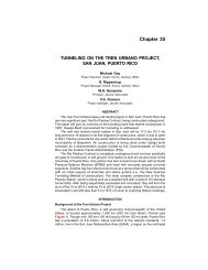
The Metropolitan Water District (MWD) of Southern California is constructing the<br />
<strong>Inland</strong> <strong>Feeder</strong> <strong>Project</strong>, which involves over 88 km (55 miles) of pipelines and tunnels to<br />
convey 31 m 3 /sec (1,100 cfs) of raw water from the State of California’s facilities at<br />
Devil Canyon, near San Bernardino to MWD’s new Diamond Valley Reservoir, near<br />
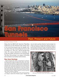
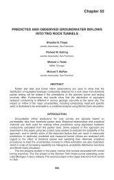
Hemet. The <strong>Riverside</strong> <strong>Badlands</strong> <strong>Tunnel</strong> is a 13 km (8 mile) long segment of the <strong>Inland</strong><br />
<strong>Feeder</strong>. The tunnel is located about 100 km (65 miles) east of downtown Los Angeles.<br />
It follows a north-south alignment from Redlands, in San Bernardino County, to just<br />
south of State Route 60, in <strong>Riverside</strong> County (Figure 1) and traverses the Crafton Hills<br />
and San Timoteo <strong>Badlands</strong> at a depth ranging from about 15 to 260 m (50 to 850 ft). A<br />
rural area of dissected hills known as “the <strong>Badlands</strong>” overlies a portion of the tunnel<br />
alignment. Most of the construction work was staged at the Gilman Portal located at<br />
the south end of the tunnel and the Opal Portal, at the north end, was used as an exit<br />
994
CHALLENGES BETWEEN CONCEPT AND COMPLETION 995<br />
Figure 1.<br />
<strong>Tunnel</strong> alignment<br />
portal to remove the TBM and place backfill around the pipe installed in the tunnel as a<br />
final lining.<br />
Design of this 3.65 m (12 ft) diameter tunnel presented many challenges that had<br />
to be addressed in order to take the project from concept to reality. These challenges<br />
included: diverse ground conditions consisting of weak sedimentary rocks; strong,<br />
fractured metamorphic rocks; and alluvium, all of which were below the groundwater<br />
table; developing a cost effective tunnel design for the wide range of ground<br />
conditions; mitigating potential construction risks; and preparing a Contract that would<br />
allow flexibility for the contractor and also fairly allocate the risk between MWD and the<br />
contractor. This paper examines how these challenges were successfully addressed<br />
during design and construction of this project.<br />
DESIGN CONSIDERATIONS<br />
Design evaluations for the project focused on a several key issues: accurately<br />
characterizing the ground and groundwater conditions; identifying appropriate tunnel<br />
excavation methods; developing initial tunnel support and final lining designs;<br />
determining requirements for portal and shaft excavations; and developing a cost<br />
effective contract package that included suitable risk management provisions. A<br />
detailed discussion of all of these topics is beyond the scope of this paper, however,<br />
some of the more critical issues are briefly discussed in the following paragraphs.<br />
Anticipated Ground Conditions<br />
Fundamental to the design approach adopted for this project was the completion of<br />
a thorough geotechnical investigation program to accurately characterize the ground<br />
conditions along the tunnel alignment. This program was described previously (see<br />
Redd et al., 1997 and DMJM/WCC, 1997). The results of these investigations indicated<br />
that three distinct geologic units would be encountered in the tunnel in the following
996 2003 RETC PROCEEDINGS<br />
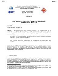
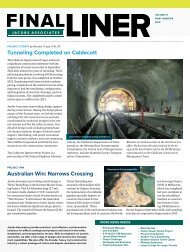
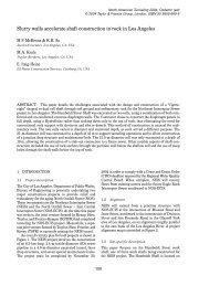
Figure 2.<br />
Geologic profile along tunnel<br />
proportions: 10 percent soft ground (alluvium); 66 percent weak sedimentary rock (San<br />
Timoteo Formation); and 24 percent strong but variably fractured and sheared hard rock<br />
(metamorphic rocks). Several fault zones were also identified that crossed the tunnel<br />
alignment. The alluvium typically consists of dense to very dense silty and gravelly sands<br />
with local silt and clay layers. The San Timoteo Formation is a weak sedimentary<br />
formation that varies in strength from about 0.7 to 13.8 MPa (100 to 2,000 psi), except<br />
where the formation is uncemented and its strength is negligible. The metamorphic rocks<br />
are stronger, exhibiting strength values generally in the range of about 35 to 175 MPa<br />
(5,000 to 25,000 psi). Except for limited areas near the portals, approximately 90% of the<br />
tunnel is below the groundwater level with levels that range up to 100 m (330 ft) above<br />
the tunnel invert. Figure 2 is a geologic profile that shows the distribution of the geologic<br />
units along the tunnel. Several alternative tunnel profiles were evaluated during design<br />
that offered more uniform geology, however, these profiles were determined to be less<br />
desirable due to cost, constructability, and operational disadvantages.<br />
The tunnel alignment was divided into ten reaches that were established based on<br />
the geologic units expected in the tunnel. These reaches are summarized in Table 1.<br />
Anticipated ground conditions included: raveling, running, and flowing ground in the<br />
alluvium; raveling, squeezing, and flowing ground in the San Timoteo Formation; and<br />
moderately jointed, blocky and seamy, and crushed rock in the metamorphic rocks. A<br />
more detailed discussion of the anticipated ground conditions is provided in Redd et al.<br />
(1997) and in the Geotechnical Design Summary Report [GDSR] (DMJM/WCC, 1997).<br />
<strong>Tunnel</strong> Design Approach<br />
Some of the important considerations that were addressed during design included:<br />
Need for positive groundwater control measures to prevent flowing ground in<br />
the alluvium.<br />
Potential for overstressed conditions in the weak San Timoteo Formation.<br />
Strong, variably fractured and sheared metamorphic rocks<br />
Highly fractured, crushed metamorphic rock and fault gouge in the Banning<br />
Fault zone (and other faults) under hydrostatic heads up to 100 m (330 ft).<br />
Uncemented zones in the San Timoteo Formation which could flow.<br />
Initial ground support requirements in the expected raveling, running, flowing,<br />
highly fractured, and crushed ground with low stand up time.<br />
Design of a watertight final lining for the tunnel to withstand the internal water<br />
pressures and external ground water pressures.
CHALLENGES BETWEEN CONCEPT AND COMPLETION 997<br />
Table 1.<br />
Summary of geologic reaches for tunnel<br />
Reach<br />
1 762<br />
(2,500 ft)<br />
2 823<br />
(2,700 ft)<br />
3 2,164<br />
(7,100 ft)<br />
4 1,372<br />
(4,500 ft)<br />
5 152<br />
(500 ft)<br />
6 2,012<br />
(6,600 ft)<br />
7 335<br />
(1,100 ft)<br />
8 2,988<br />
(9,800 ft)<br />
9 945<br />
(3,100 ft)<br />
10 1,159<br />
(3,800 ft)<br />
Length<br />
(m) Geologic Unit Primary Soil/Rock Types<br />
Alluvium<br />
San Timoteo<br />
Formation<br />
Metamorphic<br />
Rocks<br />
San Timoteo<br />
Formation<br />
Alluvium<br />
San Timoteo<br />
Formation<br />
Alluvium<br />
San Timoteo<br />
Formation<br />
Metamorphic<br />
Rocks<br />
San Timoteo<br />
Formation<br />
Clean, silty, and gravelly<br />
sand<br />
Natural Groundwater<br />
Head Range (m)<br />
0<br />
Sandstone, conglomerate 0 to 24<br />
(0 to 80 ft)<br />
Gneiss 24 to 100<br />
(80 to 330 ft)<br />
Sandstone, conglomerate 18 to 95<br />
(60 to 310 ft)<br />
Clean and silty sand, some<br />
silt and clay beds<br />
Sandstone, conglomerate,<br />
siltstone/claystone<br />
Clean and silty/clayey sand,<br />
some silt and clay beds<br />
Sandstone, siltstone/<br />
claystone, conglomerate<br />
15 to 20<br />
(50 to 65 ft)<br />
15 to 20<br />
(50 to 65 ft)<br />
14 to 20<br />
(45 to 65 ft)<br />
20 to 85<br />
(65 to 280 ft)<br />
Gneiss 46 to 55<br />
(150 to 180 ft)<br />
Sandstone, siltstone/<br />
claystone<br />
0 to 64<br />
(0 to 210 ft)<br />
Table 2.<br />
Feasible tunnel excavation methods<br />
Reaches Geologic Unit Drill-and-Blast Roadheader TBM<br />
Soft Ground<br />
Shield<br />
1,5,7 Alluvium X X<br />
2,4,6,8 San Timoteo Formation X X<br />
3,9 Metamorphic Rocks X X<br />
In addition, it was considered important to develop the Contract Documents in a way<br />
that would promote cost effective tunnel construction while also managing MWD’s risks.<br />
<strong>Tunnel</strong> Excavation Methods. Several excavation methods were determined to<br />
be feasible for the project, depending on the strength and character of the ground<br />
(Table 2). In order to provide flexibility and allow the use of different excavation<br />
methods in the various tunnel reaches, two intermediate shaft sites were made<br />
available, at the contractor’s option. These 36 and 45 m (120 and 150 ft) deep shafts<br />
were located in Live Oak and San Timoteo Canyons, respectively, near the third points<br />
of the tunnel (Figure 1). This gave the contractor the ability to mine the tunnel using up<br />
to four headings (i.e., both portals and the two shafts).<br />
Final <strong>Tunnel</strong> Lining. Due to water quality concerns, it was decided that a<br />
watertight lining was required to prevent groundwater infiltration into the tunnel. The<br />
static hydraulic grade line results in design hydrostatic pressures corresponding to<br />
about 58 to 73 m (190 to 240 ft) of head. In order to encourage competitive bids,<br />
designs for both welded steel pipe and reinforced concrete cylinder pipe were
998 2003 RETC PROCEEDINGS<br />
developed. Low density cellular concrete (LDCC) was specified as a backfill material<br />
around the pipe to reduce the risk of pipe flotation; facilitate the backfilling long<br />
sections of pipe; and provide corrosion protection for the pipe.<br />
Contracting Approach. The contracting approach developed for the project<br />
allowed the contractor flexibility where possible, subject to certain limitations. Some of<br />
the specific requirements that had to be complied with included:<br />
Positive groundwater control in the alluvium reaches.<br />
Drilling of probe holes and pre-excavation grouting in certain defined intervals<br />
of the tunnel.<br />
Shielded TBM’s were required due to the low strength of the San Timoteo<br />
Formation<br />
Mining operations limited at the Opal Portal to day shift only.<br />
The amount of pre-excavation grouting required was uncertain and this work was<br />
paid for on a force-account basis to minimize the risk to both the owner and contractor.<br />
Other risk management provisions that were incorporated into the Contract included a<br />
GDSR, Disputes Review Board, and Escrow Bid Documents. The time for completion<br />
was increased to about 60 months to allow the contractor the flexibility to excavate the<br />
tunnel from one heading or multiple headings.<br />
CONSTRUCTION PHASE<br />
The project was bid in 1998 and the Contract awarded to a joint venture of Shank/<br />
Balfour Beatty (SBB) for $113 million, which included a $5 million allowance for probe<br />
drilling and pre-excavation grouting. Construction began in October of 1998 with the<br />
excavation of the Gilman Portal and dewatering work at the two intermediate shafts.<br />
<strong>Tunnel</strong> excavation was carried out from November 1999 through July 2001.<br />
<strong>Tunnel</strong> Construction Approach<br />
The main tunnel staging area was established at the Gilman Portal and all<br />
tunneling operations and the majority of the pipe installation activities were carried out<br />
from this site. The two optional intermediate shafts, at San Timoteo and Live Oak<br />
Canyons, were used for ventilation, access during tunneling, and access to place the<br />
LDCC backfill. The entire tunnel was mined with the same shielded TBM designed to<br />
handle soft ground, weak rock, and hard rock. Precast concrete segments, 8 inches<br />
thick, were installed for initial support. The 4-segment ring was expanded with<br />
hydraulic jacks as it was pushed out of the tail shield and screw jacks were used to<br />
secure the expanded segment rings.<br />
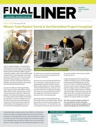
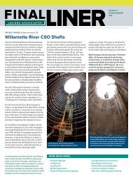
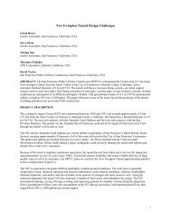
TBM Description. The TBM was a fully shielded machine designed and<br />
assembled by SBB (Figure 3). Hitachi Zosen manufactured the TBM body and tail<br />
shield. The hydraulically driven cutterhead was configured with 43 cm (17 in) diameter<br />
disc cutters and the machine was advanced with thrust jacks bearing against the<br />
precast concrete segment supports. Muck was removed from the plenum with a 76 cm<br />
(30 in) diameter screw conveyor. Key machine details are provided in Table 3.<br />
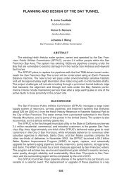
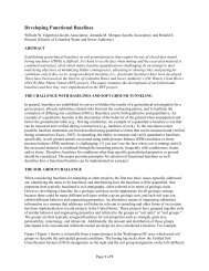
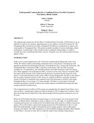
TBM Progress Rates. SBB normally employed two mining shifts and a single<br />
maintenance shift 5 days per week. The overall average advance rate for the tunnel<br />
was about 30 m/day (99 ft/day). As indicated in Table 4, the advance rates are even<br />
higher if non-productive days, for grouting and drilling drain holes ahead of the TBM,<br />
are discounted. Making this adjustment increases the average advance rate to about<br />
43 m/day (141 ft/day). Advance rates in Reaches 1, 5, and 6 were particularly<br />
impressive averaging over 60 m/day (200 ft/day) [Table 4]. Figure 4 shows the tunnel
CHALLENGES BETWEEN CONCEPT AND COMPLETION 999<br />
Figure 3.<br />
Shielded TBM used to excavate tunnel<br />
Table 3.<br />
TBM design details<br />
TBM Diameter<br />
4.8 m (15.9 ft)<br />
Total Horsepower<br />
930 kW (1,250 Hp)<br />
No. of Thrust Jacks 12<br />
Total Thrust Force<br />
16,900 kN (3,800,000 lbs)<br />
Cutterhead Torque<br />
1,176,300 m-kN (867,000 ft-lbs)<br />
Cutterhead Speed<br />
0 to 8 rpm<br />
No. and Size of Cutters<br />
32–43 cm (17 in)<br />
progress graphically. The best day and best week (5 days) were 83 and 387 m (272<br />
and 1,270 ft), respectively.<br />
Pre-excavation Grouting. Probe drilling ahead of the TBM and pre-excavation<br />
grouting provisions were included in the Contract to control large, potential<br />
groundwater inflows associated with the expected fault zones. Pre-excavation grouting<br />
was also provided to control flowing ground conditions in uncemented portions of the<br />
San Timoteo Formation. Table 5 compares the estimated and actual grouting<br />
quantities. It should be noted that drain holes and dewatering were used, in lieu of<br />
grouting in Reaches 2 and 4, which decreased the amount of grouting performed<br />
during construction.<br />
Groundwater Inflows. Groundwater inflows into the tunnel were estimated in the<br />
GDSR for the tunnel reaches (Table 1). Total cumulative inflows were estimated to be<br />
168 L/sec (2,650 gpm), assuming that pre-excavation grouting, as discussed above,<br />
would be used to reduce inflows associated with fault zones and flowing ground.<br />
Figure 5 compares the estimated and actual groundwater inflows into the tunnel.
1000 2003 RETC PROCEEDINGS<br />
Figure 4.<br />
<strong>Tunnel</strong> excavation progress<br />
Table 4.<br />
Average TBM advance rates<br />
Reach<br />
Formation<br />
Overall Average<br />
Advance<br />
Rate (m/day)<br />
1 Alluvium 62<br />
(203 ft/day)<br />
2 San Timoteo Formation 19<br />
(62 ft/day)<br />
3 Metamorphic Rocks 21.6<br />
(71 ft/day)<br />
4 San Timoteo Formation 14<br />
(46 ft/day)<br />
5 Alluvium 62<br />
(204 ft/day)<br />
6 San Timoteo Formation 62<br />
(203 ft/day)<br />
7 Alluvium 11.6<br />
(38 ft/day)<br />
8 San Timoteo Formation 55<br />
(181 ft/day)<br />
9 Metamorphic Rocks 46.3<br />
(152 ft/day)<br />
10 San Timoteo Formation 41<br />
(134 ft/day)<br />
Average Advance<br />
Rate, excluding<br />
grouting (m/day)<br />
Comments<br />
— No grouting req’d<br />
24.7<br />
(81 ft/day)<br />
30.2<br />
(99 ft/day)<br />
38.4<br />
(126 ft/day)<br />
Mined one shift per<br />
day at times<br />
— No grouting req’d<br />
— No grouting req’d<br />
17.4<br />
(57 ft/day)<br />
Mined one shift per<br />
day<br />
— No grouting req’d<br />
— No grouting req’d<br />
— No grouting req’d
CHALLENGES BETWEEN CONCEPT AND COMPLETION 1001<br />
Table 5.<br />
Comparison of estimated and actual grouting quantities<br />
Reach Feature<br />
2 Reservoir<br />
Canyon Fault,<br />
Flowing<br />
ground<br />
Cement<br />
(kg)<br />
163,400<br />
(360,000<br />
lbs)<br />
3 Banning Fault 817,200<br />
(1,800,000<br />
lbs)<br />
4 Flowing<br />
ground<br />
8 Flowing<br />
ground<br />
10 Fault D 272,400<br />
(600,000<br />
lbs)<br />
Totals<br />
Estimated Quantities<br />
Microfine<br />
(kg)<br />
163,400<br />
(360,000<br />
lbs)<br />
817,200<br />
(1,800,000<br />
lbs)<br />
Sodium<br />
Silicate<br />
(L)<br />
3,917,500<br />
(1,035,000<br />
gal)<br />
— — 1,449,700<br />
(383,000<br />
gal)<br />
— — 870,600<br />
(230,000<br />
gal)<br />
1,253,000<br />
(2,760,000<br />
lbs)<br />
272,400<br />
(600,000<br />
lbs)<br />
1,253,000<br />
(2,760,000<br />
lbs)<br />
Cement<br />
(kg)<br />
26,700<br />
(58,750<br />
lbs)<br />
— 1,060,600<br />
(2,336,030<br />
lbs)<br />
Actual Quantities<br />
Microfine<br />
(kg)<br />
108,100<br />
(238,170<br />
lbs)<br />
383,400<br />
(844,510<br />
lbs)<br />
Sodium<br />
Silicate<br />
(L)<br />
591,000<br />
(156,140<br />
gal)<br />
0 0 210,600<br />
(55,640<br />
gal)<br />
0 0 0<br />
— 0 0 0<br />
6,237,700<br />
(1,648,000<br />
gal)<br />
1,087,200<br />
(2,394,780<br />
lbs)<br />
491,500<br />
(1,082,680<br />
lbs)<br />
0<br />
801,600<br />
(211,780<br />
gal)<br />
Figure 5.<br />
Comparison of estimated and actual groundwater inflows
1002 2003 RETC PROCEEDINGS<br />
<strong>Tunnel</strong>ing Challenges<br />
For the most part ground conditions encountered in the tunnel were as described<br />
in the GDSR. However, difficult conditions were encountered creating challenges that<br />
had to be overcome.<br />
Alluvial Valleys—San Timoteo and Live Oak Canyons. The tunnel had to cross<br />
two alluvial valleys at San Timoteo and Live Oak Canyons. The Contractor was<br />
required to design and implement appropriate groundwater control measures for<br />
mining through the saturated alluvium. Feasible approaches outlined in the GDSR<br />
included dewatering, use of an EPB tunneling machine, and jet grouting. Chemical<br />
grouting methods were considered to be only marginally applicable due to the cost and<br />
high fines content of the alluvium. SBB elected to dewater the alluvium and installed<br />
23 dewatering wells in San Timoteo Canyon and 10 wells in Live Oak Canyon. The<br />
wells were typically spaced 15 m (50 ft) apart alternating on each side of tunnel<br />
centerline and were designed to extend 3 to 7.5 m (10 to 25 ft) below tunnel invert.<br />
Dewatering started in San Timoteo Canyon (Reach 7) 8 weeks prior to the<br />
anticipated TBM arrival date. However, well yields were low and piezometer readings<br />
indicated that groundwater levels were not lowered sufficiently as they ranged from<br />
about 1.5 to 6 m (5 to 20 ft) above the tunnel crown when the TBM arrived at Reach 7.<br />
SBB considered that the ineffective dewatering was due to the ground having a lower<br />
permeability than expected, and decided that the ground could be controlled with the<br />
TBM by operating it in a partially pressurized mode (i.e. quasi-EPB) utilizing the screw<br />
conveyor. Unfortunately, the TBM was halted soon after entering the alluvium when<br />
silty sands flowed through the TBM and into the heading. At this point, it was obvious<br />
that tunneling could not proceed without a more positive means to control the flowing<br />
ground and SBB decided to chemically grout the rest of the alluvium in this tunnel<br />
reach. Drilling of vertical grout holes in a 3-hole pattern was initiated by as many as 5<br />
drill rigs. Holes were drilled on 2.1 m (7 ft) centers, and chemical grout (sodium<br />
silicate) was injected through sleeve port grout pipes in several stages to treat the<br />
tunnel zone. Within ten days of initiating the grouting work, mining resumed and the<br />
grouting production allowed mining to proceed on a single shift basis in which an<br />
average of 18 m (60 ft) of tunnel was excavated per day.<br />
While the chemical grouting operation in San Timoteo Canyon was successful, it<br />
was expensive and required complete surface access along the tunnel. Because<br />
similar ground conditions were anticipated ahead in Live Oak Canyon (Reach 5), and<br />
because the performance of SBB’s dewatering system in Reach 5 had also indicated<br />
insufficient dewatering, there was concern that chemical grouting might also be<br />
required in this canyon. However, conflicts with existing residences and nearby water<br />
wells created difficulties for a chemical grouting approach. In addition, experience<br />
gained from the installation of a new water well for one of the residents suggested that<br />
the permeability might be higher than originally anticipated in this canyon. Recognizing<br />
the constraints to grouting, the actual performance of SBB’s dewatering system, and<br />
the apparent higher permeability of the alluvium, SBB was directed to install two<br />
additional wells extending some 24 m (80 ft) below tunnel invert and into the San<br />
Timoteo Formation. These deeper wells produced an average flow of 14 L/sec<br />
(225 gpm) each and quickly lowered the groundwater level in the narrow canyon. By<br />
the time the TBM arrived at Reach 5, the groundwater level had been lowered to below<br />
the tunnel invert. As a result, mining proceeded through the alluvium in Reach 5<br />
without incident at an average rate of about 60 m/day (200 ft/day) [Table 4].<br />
Reach 4—San Timoteo Formation. North of Live Oak Canyon, in Reach 4, the<br />
groundwater level in the San Timoteo Formation gradually rises from about 15 m (50 ft)<br />
above the tunnel crown to over 60 m (200 ft) at a location several thousand feet north of<br />
the canyon. South of Live Oak Canyon, in Reach 6, the San Timoteo Formation was
CHALLENGES BETWEEN CONCEPT AND COMPLETION 1003<br />
excellent for tunneling, as the TBM cut the ground easily but the ground was strong<br />
enough to have good stand up time and had sufficient silt and clay fines to prevent water<br />
problems. As anticipated, the formation became less cemented, weaker, and sandier as<br />
the tunnel proceeded north. Eventually the weaker, more pervious ground in combination<br />
with the higher groundwater levels led to significant problems about 1 km (3,300 ft) north<br />
of Live Oak Canyon where flowing ground with groundwater inflows in excess of 25 L/sec<br />
(400 gpm) halted the TBM. The water inflows decreased to about 5 to 6 L/sec (80 to<br />
100 gpm), however, mining could not proceed in such unstable ground conditions.<br />
The GDSR anticipated flowing ground being encountered and provided for the<br />
use of chemical grout (sodium silicate) to control this behavior. SBB planned to install<br />
sleeve port pipes for grouting using the lost point drilling method. Before this could be<br />
done, it was necessary to first stabilize the face and ground around the machine. This<br />
was achieved by chemical grouting through short pipes driven into the face and though<br />
holes cut in the shield. After completing this initial grouting, sleeve port grout pipes 9 m<br />
(30 ft) long were installed ahead of the TBM and chemical grout injected. Then the<br />
head was cleared of cobbles that had collected in the buckets and the head was<br />
turned. Mining recommenced but before a full 1.2 m (4 ft) shove could be completed<br />
the ground flowed into the tunnel and mining had to be stopped. This same chemical<br />
grouting process was repeated several times without success over the next 10 weeks,<br />
probably because the grout was not penetrating far enough into the formation to<br />
stabilize enough ground around the tunnel perimeter.<br />
Considering this situation, MWD investigated the feasibility of installing a deep<br />
well from the ground surface in this area. The landowner was agreeable and<br />
dewatering analyses indicated that a well installed to a depth of about 150 m (500 ft)<br />
would be required to draw the groundwater level down to near the tunnel invert. MWD<br />
directed SBB to install a deep well located about 107 m (350 ft) ahead of the tunnel<br />
heading. In addition, drain holes 45 m (150 ft) long were drilled ahead of the TBM and<br />
a pump was installed in a well drilled in the invert of the tunnel.<br />
The deep well was very effective, producing a flow rate of approximately 27 L/sec<br />
(425 gpm), and the drain holes yielded flows of about 6 L/sec (100 gpm) each. The<br />
combined result of these dewatering measures was an immediate improvement in<br />
conditions at the tunnel heading, and mining operations resumed. A second deep well<br />
was also installed approximately 150 m (500 ft) north of the first well to ensure that the<br />
remainder of the reach could be successfully mined. After a total delay of nearly<br />
12 weeks, mining continued at a rate of 27 m/day (90 ft/day) to Reach 3.<br />
Potential flowing ground conditions were also expected in the San Timoteo<br />
Formation in Reach 2. Because of the effectiveness of the dewatering wells in Reach 4<br />
and the difficulty in grouting from the tunnel, it was decided to use the dewatering<br />
approach for Reach 2. Five wells were installed and they proved to be very effective in<br />
controlling the flowing ground and Reach 2 was mined without incident.<br />
Final Lining<br />
The Contract allowed the contactor to install a final lining of either reinforced<br />
concrete cylinder pipe or welded steel pipe. SBB selected the steel pipe option and<br />
elected to fabricate the pipe in 18 m (60 ft) sections with lap welded joints. The tunnel<br />
was prepared for the pipe laying operation and particular attention was given to<br />
installing a panning system that allowed water to be drained to the invert while<br />
ensuring that the LDCC would not infiltrate and plug the drains. Once proper drainage<br />
was established, the steel pipes were installed in the tunnel using a special pipe carrier<br />
designed by SBB. The pipe was transported and installed at a rate of about 120 m<br />
(400 ft) or 7 sections per day. After installing and welding the pipe sections, stulls were
1004 2003 RETC PROCEEDINGS<br />
placed in the pipe 3 m (10 ft) apart to prepare for the LDCC backfill operation. The<br />
LDCC backfill, with a design strength of 2.75 MPa (400 psi), was placed in five lifts.<br />
Any voids remaining outside the pipe were contact grouted with a neat cement mix. A<br />
2 cm ( 3 ⁄4 in) thick field-applied mortar lining completed the pipe installation.<br />
DISCUSSION AND CONCLUSIONS<br />
Water started flowing through the completed tunnel in December 2002. To-date<br />
the total construction cost is about 7% above the $113 million bid price, but still<br />
substantially below the Engineer’s Estimate. The project was also completed<br />
approximately one year ahead of schedule. Although there were some significant<br />
challenges during the tunnel excavation work, the ability of the parties involved to work<br />
together to solve these problems has resulted in an extremely successful project.<br />
Other key factors that contributed to the success of the project were the accurate<br />
baseline for anticipated ground conditions; Contract Documents that offered bidders<br />
flexibility in a number of areas; and the proactive mitigation of adverse ground<br />
conditions. The project is an excellent example of the use of a shielded TBM to handle<br />
extremely diverse ground conditions. Overall advance rates achieved by this TBM are<br />
impressive considering the variable ground conditions. Special measures such as<br />
probing and grouting ahead of the TBM and, in particular, deep dewatering wells were<br />
demonstrated to be effective for controlling adverse ground conditions. Another aspect<br />
demonstrated by this project is the advantage of working from a portal. The Gilman<br />
Portal site proved to be ideal, supporting very efficient mining and muck disposal<br />
operations and also allowing long pipe sections to be installed in the tunnel,<br />
significantly reducing the amount of field welding required.<br />
REFERENCES<br />
Redd, R.R., J.T. Waggoner, J.S. Hill, S.J. Klein, and D.B. Desai, 1997, “Anticipated<br />
Ground Conditions for the <strong>Riverside</strong> <strong>Badlands</strong> <strong>Tunnel</strong>,” RETC Proceedings, SME/<br />
AIME, Golden, CO, p. 457–471.<br />
DMJM Woodward-Clyde Consultants (DMJM/WCC), 1997, “Geotechnical Design<br />
Summary Report,” Report prepared for Metropolitan Water District of Southern<br />
California, October 29.