Respironics BIPAP Auto SV - Impact Biomedical Corp.
Respironics BIPAP Auto SV - Impact Biomedical Corp.
Respironics BIPAP Auto SV - Impact Biomedical Corp.

Create successful ePaper yourself
Turn your PDF publications into a flip-book with our unique Google optimized e-Paper software.
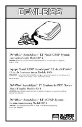
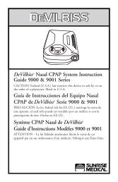
auto<strong>SV</strong><br />
TM<br />
with<br />
Encore SmartCard ®<br />
Provider Manual
This BiPAP system is covered by one or more of the following patents: U.S. Patent Nos. 5,148,802; 5,239,995; 5,313,937;<br />
5,433,193; 5,632,269; 5,803,065; 6,029,664; 6,305,374 and 6,539,940; Australian Patent Nos. 638054; 661575; 698519;<br />
723681; 734319 and 733655; Canadian Patent Nos. 2,024,477; 2,162,981 and 2,259,795; European Patent No. EP0425092;<br />
German Patent No. 69021681.5-08; and Japanese Patent Nos. 2832812; 2137336; and 2926392. Other U.S. and foreign<br />
patents pending.<br />
© 2007 <strong>Respironics</strong>, Inc. and its affiliates. All rights reserved.
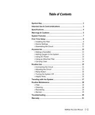
Table of Contents<br />
Chapter 1: Package Contents.......................................................................................................................................1-1<br />
Chapter 2: Warnings and Cautions.............................................................................................................................2-1<br />
2.1 Warnings............................................................................................................................................2-1<br />
2.2 Cautions............................................................................................................................................2-3<br />
2.3 Intended Use.....................................................................................................................................2-3<br />
2.4 Contraindications............................................................................................................................2-3<br />
2.5 Patient Precautions..........................................................................................................................2-4<br />
Chapter 3: Introduction..............................................................................................................................................3-1<br />
3.1 Overview............................................................................................................................................3-1<br />
3.2 Operation..........................................................................................................................................3-1<br />
3.2.1 Pressure Controls..................................................................................................................3-2<br />
3.2.2 Back-up Breath Rate Controls..............................................................................................3-3<br />
3.2.3 Ramp..........................................................................................................................................3-5<br />
3.2.4 Digital <strong>Auto</strong>-Trak Sensitivity...............................................................................................3-5<br />
3.3 Access Levels.....................................................................................................................................3-7<br />
3.3.1 Provider Mode Access Level..................................................................................................3-7<br />
3.3.2 User Mode Access Level.........................................................................................................3-8<br />
3.4 Definitions, Acronyms, and Abbreviations....................................................................................3-9<br />
3.5 Symbol Key ........................................................................................................................................3-10<br />
3.6 Service...............................................................................................................................................3-10<br />
Chapter 4: Controls and Displays...............................................................................................................................4-1<br />
4.1 Controls and Displays.....................................................................................................................4-1<br />
4.1.1 Display Screen.........................................................................................................................4-1<br />
4.1.2 Control Buttons....................................................................................................................4-3<br />
4.1.3 Indicators................................................................................................................................4-4<br />
4.1.4 Audible Alarms and Indicators.............................................................................................4-4<br />
4.2 Navigating the Screens....................................................................................................................4-4<br />
4.2.1 LED Backlight for Buttons..................................................................................................4-5<br />
4.3 Patient Circuit Connection............................................................................................................4-5<br />
4.4 Rear Panel..........................................................................................................................................4-5<br />
4.5 SmartCard.........................................................................................................................................4-6<br />
Chapter 5: Setup............................................................................................................................................................5-1<br />
5.1 Preparing the Device........................................................................................................................5-1<br />
5.1.1 Installing the Air Filters......................................................................................................5-1<br />
5.1.2 Assembling the Patient Circuit............................................................................................5-1<br />
5.1.3 Supplying Power to the Device.............................................................................................5-2<br />
5.1.4 Startup.....................................................................................................................................5-3<br />
5.1.5 Entering Provider Mode.......................................................................................................5-5<br />
5.1.6 Performance Verification......................................................................................................5-5<br />
5.2 Setting up the Device......................................................................................................................5-5<br />
5.3 Connecting the Patient...................................................................................................................5-6<br />
5.4 Setting up the SmartCard...............................................................................................................5-6<br />
5.4.1 Downloading Data.................................................................................................................5-6<br />
5.4.2 Programming a SmartCard....................................................................................................5-6<br />
5.4.3 Changing Settings Using a SmartCard................................................................................5-6<br />
Chapter 6: Changing Settings.....................................................................................................................................6-1<br />
6.1 Changing Settings in Provider Mode............................................................................................6-1<br />
6.1.1 Navigating Screens in Provider Mode.................................................................................6-1<br />
6.1.2 Changing Settings in Provider Mode..................................................................................6-2<br />
6.2 Monitoring Measured Parameters ..............................................................................................6-8<br />
6.3 Changing Settings in User Mode...................................................................................................6-10<br />
Provider Manual
Chapter 7: Alarms.........................................................................................................................................................7-1<br />
7.1 Alarm Introduction.........................................................................................................................7-1<br />
7.1.1 Overview of Alarm Behavior.................................................................................................7-1<br />
7.2 System Alarms....................................................................................................................................7-3<br />
7.2.1 System Error Alarm................................................................................................................7-3<br />
7.2.2 Card Error Alarm...................................................................................................................7-3<br />
7.2.3 Pressure Regulation High Alarm.........................................................................................7-4<br />
7.2.4 Pressure Regulation Low Alarm...........................................................................................7-4<br />
7.2.5 Low Pressure Support Alarm.................................................................................................7-4<br />
7.2.6 Prescription Complete Alarm...............................................................................................7-4<br />
7.3 Patient Alarms..................................................................................................................................7-5<br />
7.3.1 Apnea Alarm.............................................................................................................................7-5<br />
7.3.2 Patient Disconnect Alarm.....................................................................................................7-5<br />
7.3.3 Low Minute Ventilation Alarm............................................................................................7-6<br />
7.4 Power Alarms....................................................................................................................................7-7<br />
7.5 Alarm Summary Tables.......................................................................................................................7-8<br />
Chapter 8: Cleaning and Maintenance......................................................................................................................8-1<br />
8.1 Cleaning the Device........................................................................................................................8-1<br />
8.1.1 Cleaning and Disinfection for Multiple Users..................................................................8-1<br />
8.2 Cleaning or Replacing the Inlet Filters.......................................................................................8-1<br />
8.3 Maintenance.....................................................................................................................................8-2<br />
8.4 Carrying Case....................................................................................................................................8-2<br />
Chapter 9: Adding Supplemental Oxygen...................................................................................................................9-1<br />
9.1 Adding Supplemental Oxygen.........................................................................................................9-1<br />
9.2 Supplemental Oxygen Concentrations..........................................................................................9-2<br />
Chapter 10: Circuits and Accessories.........................................................................................................................10-1<br />
10.1 Circuit Configurations.................................................................................................................10-1<br />
10.2 Circuits and Accessories................................................................................................................10-1<br />
10.3 Masks, Exhalation Ports, and Related Accessories....................................................................10-2<br />
10.4 Humidifiers......................................................................................................................................10-2<br />
10.5 Software...........................................................................................................................................10-2<br />
Chapter 11: Operational Verification........................................................................................................................11-1<br />
11.1 System Verification.........................................................................................................................11-1<br />
11.2 Alarm Verification.........................................................................................................................11-2<br />
Chapter 12: Specifications............................................................................................................................................12-1<br />
Appendix A: Error Codes..............................................................................................................................................A-1<br />
Appendix B: EMC Information.....................................................................................................................................B-1<br />
Provider Manual
1-1<br />
Chapter 1: Package Contents<br />
BiPAP auto<strong>SV</strong> with<br />
Encore® Pro SmartCard<br />
Carrying Case<br />
Reusable Gray<br />
Foam Filters<br />
Disposable<br />
Ultra-fine Filter<br />
User Manual<br />
Provider Manual<br />
Filter Cap<br />
Power Cord<br />
Flexible Tubing<br />
1.83 m (6 ft.) x 22 mm i.d.<br />
External AC Power Supply<br />
Provider Manual
1-2<br />
Provider Manual
2-1<br />
Chapter 2: Warnings and Cautions<br />
WARNING:<br />
CAUTION:<br />
NOTE:<br />
Caution:<br />
Indicates the possibility of injury to the patient or the operator.<br />
Indicates the possibility of damage to the BiPAP auto<strong>SV</strong> device.<br />
Places emphasis on an operating characteristic.<br />
U.S. federal law restricts this device to sale by or on the order of a physician.<br />
2.1 Warnings<br />
• This manual serves as a reference. The instructions in this manual are not intended to supersede the instructions of<br />
the health care professional. The operator should read and understand this entire manual before using the device.<br />
• Long term effects of the treatment of sleep disordered breathing and/or Cheyne Stokes Respiration in patients with<br />
Congestive Heart Failure (CHF) or atrial fibrillation have not been documented. Therefore, caution should be<br />
exercised when using this device on a patient with CHF or atrial fibrillation. The clinician should assess the relative<br />
risk and benefits of the therapy on a case-by-case basis.<br />
• The device provides positive pressure ventilation and is indicated for assisted ventilation. This system does not<br />
provide ventilation with guaranteed tidal volume delivery. Patients requiring ventilation at predetermined tidal<br />
volumes are not candidates for pressure support ventilation.<br />
• This is not a life support ventilator. BiPAP auto<strong>SV</strong> is a non-continuous ventilator intended to augment patient<br />
breathing. It is not intended to provide total ventilatory support. It may stop operating with power failure or if a<br />
fault occurs in the product.<br />
• In the event of a power or device failure, audible and visual alarm signals will activate. The device must then be<br />
disconnected from the patient immediately. As is the case with most ventilators with passive exhalation ports, when<br />
power is lost, sufficient air will not be provided through the circuit, and exhaled air may be rebreathed.<br />
• At low EPAP pressures, the flow through the exhalation port may be inadequate to clear all exhaled gas from the<br />
tubing. Some rebreathing may occur. Monitor the patient appropriately.<br />
• To reduce the risk of contamination, you may place a bacteria filter in-line between the device and the patient.<br />
• The device does not have an alarm to detect occlusion of the exhalation port. Before each use, inspect the patient<br />
circuit to verify that the port is not occluded. Occlusion or partial occlusion can reduce airflow and result in<br />
rebreathing of exhaled air.<br />
• Verify the operation of the Patient Disconnect alarm with any changes in the patient circuit.<br />
• Verify that the Patient Disconnect alarm is active if required for medical reasons.<br />
• If the patient has a severe obstructive or restrictive spirometric defect, or severe daytime hypercapnia or hypoxia,<br />
then the device may not be an appropriate treatment method. This is due to the level of ventilatory support that the<br />
device provides.<br />
• Do not connect any equipment to the device unless recommended by <strong>Respironics</strong> or the health care professional.<br />
Verify that an exhalation port is present to exhaust CO 2<br />
from the circuit. If circuit accessories other than those<br />
recommended by <strong>Respironics</strong> are connected to the device, then pressure must be verified. Use of these accessories<br />
may alter the pressure received, reducing the effectiveness of treatment.<br />
• The device should be used only with masks and accessories recommended by <strong>Respironics</strong> or with those<br />
recommended by the health care professional or respiratory therapist. See Chapter 10 for approved patient circuits.<br />
A mask should not be used unless the device is turned on and operating properly. The exhalation port(s) associated<br />
with the mask should never be blocked. In the event of a power failure or machine malfunction, remove the mask.<br />
Explanation of the Warning: The device is intended to be used with special masks or connectors that have<br />
exhalation ports to allow a continuous flow of air out of the mask. When the device is turned on and functioning<br />
properly, new air from the device flushes the exhaled air out through the mask exhalation port. However, when the<br />
device is not operating, enough fresh air will not be provided through the mask, and exhaled air may be rebreathed.<br />
Rebreathing of exhaled air for longer than several minutes can in some circumstances lead to suffocation.<br />
Provider Manual
2-2<br />
• Operation of the device may be adversely affected by:<br />
– Electromagnetic fields exceeding the level of 10 V/m in the test conditions of<br />
EN 60601-1-2<br />
– Operation of high frequency (diathermy) equipment<br />
– Defibrillators, or short wave therapy equipment<br />
– Radiation (e.g., x-ray, CT)<br />
– Magnetic fields (e.g., MRI)<br />
• Do not use the device at room temperatures above 95° F (35° C). If the device is used at room temperatures above<br />
95° F (35° C), the temperature of the airflow may exceed 106° F (41° C), which could cause thermal irritation or<br />
injury to the patient’s airway.<br />
• Do not operate the device in direct sunlight or near a heating appliance because these conditions can increase the<br />
temperature of the air coming out of the device.<br />
• Do not use antistatic or electrically conductive hoses or tubing with the device.<br />
• When the device is used with an external humidifier, position the humidifier so that the water level in the humidifier<br />
is lower than the patient and the humidifier is on the same level or lower than the device. Use only <strong>Respironics</strong>approved<br />
humidifiers with the BiPAP auto<strong>SV</strong>.<br />
• If you detect any unexplained changes in the performance of the device, if the device is dropped or mishandled, if<br />
water is spilled into the enclosure, or if the enclosure is broken, seek the assistance of <strong>Respironics</strong> or an authorized<br />
service center.<br />
• Do not open the BiPAP auto<strong>SV</strong> enclosure. There are no user serviceable parts inside. Repairs and internal servicing<br />
should only be performed by an authorized service agent.<br />
• Electrical cords and cables should be periodically inspected for damage or signs of wear. Replace any damaged parts<br />
before using.<br />
• To avoid electrical shock, unplug the device before cleaning.<br />
• Pins of connectors identified with the ESD warning symbol should not be touched. Connections should not be<br />
made to these connectors unless ESD precautionary procedures are used. Precautionary procedures include methods<br />
to prevent build-up of electrostatic discharge (e.g., air conditioning, humidification, conductive floor coverings,<br />
non-synthetic clothing), discharging one’s body to the frame of the equipment or system or to earth or a large metal<br />
object, and grounding oneself by means of a wrist strap to the equipment or system or to earth.<br />
• If oxygen is used with the device, the oxygen flow must be turned off when the device is not in use.<br />
Explanation of the warning: When the device is not in operation and the oxygen flow is left on, oxygen delivered<br />
into the ventilator tubing may accumulate within the device’s enclosure. Oxygen accumulated in the ventilator<br />
enclosure will create a risk of fire.<br />
• When using oxygen with this system, a <strong>Respironics</strong> Pressure Valve must be placed in-line with the patient circuit.<br />
• Oxygen supports combustion. Oxygen should not be used while smoking or in the presence of an open flame.<br />
• When administering fixed-flow supplemental oxygen, the O 2<br />
concentration may not be constant. The inspired<br />
oxygen concentration will vary, depending on the IPAP and EPAP pressures, patient breathing pattern, and the<br />
leak rate. Substantial leaks around the mask may reduce the inspired oxygen concentration to less than the expected<br />
concentrations. Monitor the patient appropriately.<br />
• To prevent an accumulation of oxygen in the device, advise the patient to turn the device on before turning on the<br />
oxygen. Likewise, the patient must turn off the oxygen before turning off the device.<br />
• Do not use the device in the presence of a flammable anaesthetic mixture in combination with oxygen or air, or in<br />
the presence of nitrous oxide.<br />
Provider Manual
2-3<br />
2.2 Cautions<br />
• The device may only be operated at temperatures between 41° F (5° C) and 95° F (35° C).<br />
• Do not immerse the device or allow any liquid to enter the enclosure or the inlet filter.<br />
• Do not place the device in or on any container that can collect or hold water.<br />
• Condensation may damage the device. Always allow the device to reach ambient temperature before use.<br />
• Use the power cable retainer to keep the power cord from being unintentionally disconnected.<br />
NOTE:<br />
Additional warnings, cautions, and notes are located throughout this manual.<br />
2.3 Intended Use<br />
The BiPAP auto<strong>SV</strong> is intended to provide non-invasive ventilatory support to treat adult patients with OSA and Respiratory<br />
Insufficiency caused by central and/or mixed apneas and periodic breathing.<br />
2.4 Contraindications<br />
The BiPAP auto<strong>SV</strong> system should not be used on patients with the following conditions:<br />
• Patients without a spontaneous respiratory drive<br />
• Existing respiratory failure (failure to treat; risk of increased work of breathing due either to incomplete reversal of<br />
upper airway obstruction or to breathing at high lung volume, leading to worsening respiratory failure)<br />
• Pneumothorax or pneumomediastinum<br />
• Emphysematous bullae or a past history of pneumothorax (risk of pneumothorax)<br />
• Acute decompensated cardiac failure or hypotension, particularly if associated with intravascular volume depletion<br />
(risk of further hypotension or reduction in cardiac output)<br />
• Massive epistaxis or previous history of massive epistaxis (risk of recurrence)<br />
• Pneumoencephalus, recent trauma or surgery (e.g., pituitary or nasal) that may have produced cranionasopharyngeal<br />
fistula (risk of entry of air or other material into the cranial cavity)<br />
• Acute sinusitis, otitis media, or perforated ear drum<br />
• Acute or unstable cardiac failure<br />
• Nocturnal or resting angina (risk of infarction or arrhythmias)<br />
• Unstable arrhythmias<br />
• Severely obtunded or heavily sedated patients<br />
• At risk for aspiration of gastric contents<br />
• Impaired ability to clear secretions<br />
If patients are dehydrated or volume depleted, or have persistent atrial fibrillation, their cardiac filling pressures may be<br />
low. In these cases, as with any CPAP or ventilatory support, use of the device may lead to a dangerous reduction in cardiac<br />
output. The device should not be used in patients who are dehydrated or volume depleted, and should be used with extreme<br />
care in patients with atrial fibrillation.<br />
NOTE:<br />
When assessing the relative risks and benefits, the health care professional should understand that the device can<br />
be set to deliver pressures up to 30 cm H 2<br />
O. Also, in the unlikely event of certain fault conditions, a maximum<br />
static pressure of 40 cm H 2<br />
O is possible.<br />
Provider Manual
2-4<br />
2.5 Patient Precautions<br />
• The following are potential side effects of noninvasive positive pressure therapy:<br />
— Ear or sinus discomfort<br />
— Conjunctivitis<br />
— Skin abrasions due to noninvasive interfaces<br />
— Gastric distention (aerophagia)<br />
— Drying of nose, mouth or throat<br />
— Eye irritation<br />
— Skin rashes<br />
— Chest discomfort<br />
Provider Manual
3-1<br />
Chapter 3: Introduction<br />
3.1 Overview<br />
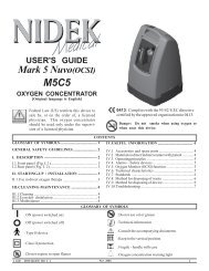
Figure 3-1 The BiPAP auto<strong>SV</strong> Device<br />
The device, shown in Figure 3-1, is a low-pressure, electrically driven ventilator system with electronic pressure control. The<br />
device’s pressure controls are adjusted to deliver pressure support for patient ventilatory assistance.<br />
The device is intended to augment patient breathing by supplying pressurized air through a patient circuit. It senses the<br />
patient’s breathing effort by monitoring airflow in the patient circuit and adjusts its output to assist in inhalation and<br />
exhalation. This assistance is provided by the administration of two levels of positive pressure. During exhalation, pressure<br />
is variably positive or near ambient. During inspiration, pressure is variably positive and always equal to or higher than the<br />
expiratory level.<br />
The device responds reliably to patient flow rates that indicate movement to inhalation or exhalation, even in the presence<br />
of most normal leaks in the patient circuit. <strong>Auto</strong>matic adjustment of this trigger threshold in the presence of leaks makes<br />
the system ideal for mask-applied ventilation assistance. The patient-controllable Rise Time feature may enhance patientventilator<br />
synchrony and patient comfort.<br />
3.2 Operation<br />
This section provides information on the following BiPAP auto<strong>SV</strong> features:<br />
• Pressure Controls<br />
• Back-up Breath Rate Controls<br />
• Ramp<br />
• Digital <strong>Auto</strong>-Trak Sensitivity<br />
Provider Manual
3-2<br />
3.2.1 Pressure Controls<br />
The device contains the following controls which are used to configure positive pressure therapies:<br />
• EPAP – The pressure maintained during expiration.<br />
• IPAP Min – The minimum pressure the device can deliver during inspiration.<br />
• IPAP Max – The maximum pressure the device can deliver during inspiration.<br />
With these controls, the device offers the following therapies:<br />
Control Settings<br />
EPAP = IPAP Min < IPAP Max<br />
Description<br />
The device provides CPAP as a base therapy.<br />
The device may automatically provide pressure<br />
support with inspiratory pressures between<br />
IPAP Min and IPAP Max to normalize patient<br />
ventilation during sleep disordered breathing<br />
events. Refer to Figure 3-2.<br />
Note: When EPAP = IPAPMin = IPAP Max, this is<br />
equivalent to traditional CPAP therapy.<br />
EPAP < IPAP Min < IPAP Max<br />
The device delivers minimum pressure support<br />
determined by the EPAP and IPAP Min controls.<br />
The device may automatically provide additional<br />
pressure support with inspiratory pressures<br />
between IPAP Min and IPAP Max to normalize<br />
patient ventilation during sleep disordered<br />
breathing events. Figure 3-3 illustrates the<br />
automatic adjustment of IPAP during a sleep<br />
disorder breathing event and during normal<br />
breathing.<br />
Note: When EPAP < IPAP Min = IPAP Max, this is<br />
equivalent to traditional bi-level therapy.<br />
IPAP max<br />
Pressure<br />
EPAP = IPAP min<br />
Flow<br />
Time<br />
Target Flow<br />
Time<br />
Figure 3-2 CPAP Therapy with <strong>Auto</strong>matic Pressure Support<br />
Provider Manual
3-3<br />
IPAP max<br />
Pressure<br />
IPAP min<br />
EPAP<br />
Flow<br />
Time<br />
Target Flow<br />
Time<br />
Figure 3-3 Bi-Level Therapy with <strong>Auto</strong>matic Pressure Support<br />
3.2.2 Back-up Breath Rate Controls<br />
In addition to the pressure controls, the device may be configured to deliver machine-triggered breaths if the patient does not<br />
spontaneously breathe at a determined rate. Back-up breaths are machine-triggered, machine-cycled breaths. The Rate and<br />
Time Insp controls are used to configure back-up breaths to one of three selections.<br />
Control Settings<br />
Back-up Rate: OFF<br />
Back-up Rate: 4-30<br />
Time Insp: .5 - 3<br />
Back-up Rate: <strong>Auto</strong><br />
Description<br />
No back-up breaths are delivered to the patient. The initiation of each<br />
breath is exclusively controlled by the patient. The device triggers to<br />
IPAP in response to spontaneous inspiratory effort, and cycles to EPAP<br />
during exhalation. Figure 3-4 illustrates the trigger and cycle concepts.<br />
This selection ensures that the patient will receive a minimum number<br />
of breaths per minute if their spontaneous breathing rate drops below the<br />
breath rate specified by the Rate control. If the patient fails to initiate an<br />
inspiration within the breath period determined by the control, the device<br />
triggers a timed breath. The duration of each breath is controlled by the<br />
Time Insp control. Figure 3-5 illustrates patient-triggered and machinetriggered<br />
breaths when the back-up rate is 4-30.<br />
With <strong>Auto</strong> selected, the back-up rate and the time of inspiration are<br />
automatically determined by the device. Spontaneous breaths are used<br />
to compute an average breath period and inspiratory period. (The 2 to 3<br />
breaths prior to central apnea may be insufficient to ventilate. Thus,<br />
tidal volumes less than 100 ml are not counted as a breath. Timed breaths<br />
are delivered in groups of 5 breaths. The First Timed breath has separate<br />
timing criteria as compared to the subsequent 4 breaths.) Figure 3-6<br />
illustrates breathing intervals when the back-up rate is <strong>Auto</strong>.<br />
Inspiration<br />
Trigger<br />
Rise Time<br />
Cycle<br />
Expiration<br />
Inspiratory Time<br />
IPAP<br />
EPAP<br />
Figure 3-4 Triggering and Cycling when the Back-Up Rate is Off<br />
Provider Manual
3-4<br />
Time Interval<br />
Based on the<br />
Rate Setting<br />
Vol (ml) P (cm H 2 O)<br />
IPAP<br />
EPAP<br />
S S T S<br />
S S T<br />
S<br />
S = Spontaneously-triggered pressure support breaths (Patient-triggered)<br />
T = Time-triggered, pressure-limited, time-cycled breath (Machine-triggered)<br />
Figure 3-5 Example of Patient-Triggered and Machine-Triggered Breaths when the Back-Up Rate is 4 - 30<br />
t a = normal breathing interval<br />
t b = breathing interval that triggers a timed breath<br />
t c = inspiration time of a timed breath<br />
t a t b t c<br />
Vol (ml) P (cm H2O)<br />
IPAP<br />
EPAP<br />
S S T S<br />
100<br />
S S T S<br />
S = Spontaneously triggered pressure support breaths (Patient-triggered)<br />
T = Time-triggered, pressure-limited, time-cycled breath (Machine-triggered)<br />
Figure 3-6 Breathing Intervals when the Back-Up Rate is <strong>Auto</strong><br />
Provider Manual
3-5<br />
3.2.3 Ramp<br />
The device is equipped with a linear ramp function. When activated, the ramp feature reduces the pressure and then gradually<br />
increases (ramps) the pressure to the prescription pressure setting so patients can fall asleep more comfortably. Figure 3–7<br />
illustrates how the ramp function works.<br />
IPAP Min<br />
Pressure<br />
EPAP<br />
Pressure<br />
Airflow<br />
Turned On<br />
Ramp Button<br />
Pressed<br />
Minimum<br />
Pressure<br />
Support<br />
Ramp Start<br />
Pressure<br />
0 cm H2O<br />
Minutes<br />
Ramp Time<br />
Linear Ramp<br />
* The minimum pressure support is defined<br />
as the lesser of 2 cm H2O and the<br />
difference between IPAP Min and EPAP<br />
pressure settings.<br />
Figure 3-7 The Ramp Function<br />
3.2.4 Digital <strong>Auto</strong>-Trak Sensitivity<br />
An important characteristic of the BiPAP auto<strong>SV</strong> device is its ability to recognize and compensate for unintentional leaks in<br />
the system and to automatically adjust its trigger and cycle algorithms to maintain optimum performance in the presence<br />
of leaks. This feature is known as Digital <strong>Auto</strong>-Trak Sensitivity. The following sections examine this function in detail by<br />
describing the leak tolerance function and sensitivity.<br />
3.2.4.1 Leak Tolerance<br />
A microprocessor monitors the total flow of the patient circuit and calculates patient flow values.<br />
A. Leak Estimation: Average and Parabolic<br />
The device uses two leak estimation algorithms. A conservation of mass algorithm is used to compute the average leak<br />
for a given pressure support relationship. This average leak is used when large leak variations are present in the system.<br />
Average leak is a high estimate during EPAP pressure and a low estimate during IPAP pressure.<br />
A better leak estimate, enabled by the digital system, is the parabolic leak algorithm. Parabolic leak is proportional to the<br />
square of the patient pressure; therefore, the leak estimate is correlated to the changing patient pressure. Both algorithms<br />
include unintentional circuit leak and are averaged over several breaths.<br />
B. Patient Flow<br />
The total circuit flow is comprised of the circuit leak and the patient flow. The calculated patient flow is the total flow<br />
minus the circuit leak. Patient flow is a primary input into the triggering and cycling mechanisms.<br />
3.2.4.2 Sensitivity<br />
An essential feature of the device’s triggering function is its ability to effectively sense spontaneous breathing efforts, which<br />
causes the ventilator to trigger to IPAP and cycle to EPAP. Because no preset sensitivity threshold can assure patient and<br />
machine synchrony with changing breathing efforts and circuit leaks, the device continuously tracks patient breathing<br />
patterns and automatically adjusts sensitivity thresholds to ensure optimum sensitivity as breathing patterns change or as<br />
circuit leaks change. The algorithm used to ensure optimum sensitivity is the Volume Trigger.<br />
Provider Manual
3-6<br />
Volume Trigger (EPAP to IPAP)<br />
The volume trigger is the method used to trigger IPAP during spontaneous breathing. The volume trigger threshold is 6 ml<br />
of accumulated patient inspiratory volume. When patient effort generates inspiratory flow causing 6 ml of volume, IPAP is<br />
triggered.<br />
Shape Trigger (EPAP to IPAP)<br />
The shape trigger is another method used to trigger IPAP during spontaneous breathing. This method continuously tracks<br />
patient inspiratory and expiratory flow and adjusts the spontaneous trigger threshold for optimum sensitivity. The shape<br />
signal appears as a shadowy image of the patient’s actual flow. The shape signal functions as a sensitivity threshold at<br />
inspiration. When the patient’s flow rate crosses the shape signal, the unit changes pressure levels. Figure 3–8 illustrates how<br />
the shape signal is superimposed onto the actual waveform to trigger to IPAP.<br />
The shape signal is created by offsetting the signal from the actual patient flow by 15 LPM and delaying it for a 300 msec<br />
period. This intentional delay causes the shape signal to be slightly behind the patient’s flow rate. A sudden change in patient<br />
flow will cross the shape signal, causing the pressure level to change.<br />
Figure 3-8 Shape Signal<br />
Tracking the patient’s flow pattern with the shape signal provides a sensitive mechanism to trigger to IPAP in response to<br />
changing breathing patterns and circuit leaks.<br />
Spontaneous Expiratory Threshold (IPAP to EPAP)<br />
The method used to cycle off IPAP during spontaneous breathing is called Spontaneous Expiratory Threshold (SET). The<br />
SET rises in proportion to the inspiratory flow rate on each breath. When the SET and the actual patient flow value are equal,<br />
the unit cycles to EPAP.<br />
Figure 3-9 Spontaneous Expiratory Threshold<br />
Provider Manual
3-7<br />
Maximum IPAP Time (IPAP to EPAP)<br />
A maximum IPAP time of 3.0 seconds acts as a safety mechanism to limit the time spent at the IPAP level during<br />
spontaneous breathing. Once the time limit is reached, the unit automatically cycles off IPAP to the EPAP level.<br />
Summary<br />
The sensitivity criteria for spontaneous breathing can be summarized as follows:<br />
Spontaneous Trigger to IPAP<br />
A transition from EPAP to IPAP occurs when one of the following conditions is met:<br />
• Patient flow exceeds the shape signal<br />
• 6 ml inspired patient volume<br />
Cycle to EPAP<br />
The transition from IPAP to EPAP occurs when one of the following conditions is met:<br />
• Spontaneous Expiratory Threshold (SET) is achieved<br />
• A 3.0 second maximum IPAP time has occurred (safety feature)<br />
3.3 Access Levels<br />
There are two levels of access:<br />
• Provider Mode<br />
• User Mode<br />
3.3.1 Provider Mode Access Level (Setup)<br />
The Provider mode unlocks additional parameters that are not available to the patient. This mode is accessed by completing<br />
the following steps:<br />
1. Plug in the device to power up the device.<br />
2. Press the Right User button and the SILENCE button simultaneously for at least two seconds (see Figure 3-10).<br />
SETUP appears in the top right corner of the display, and the EPAP Setting screen will display. This indicates that<br />
you are now in Provider mode.<br />
NOTE:<br />
It does not matter whether you press the Right User button or the SILENCE button first.<br />
Display<br />
Screen<br />
Pressure On/Off<br />
Button<br />
Heated<br />
Humidifier<br />
Button<br />
HEAT<br />
RAMP<br />
User<br />
Buttons<br />
RESET<br />
SILENCE<br />
Ramp<br />
Button<br />
Figure 3-10 Control Panel<br />
Alarm<br />
Silence<br />
Button<br />
Scroll<br />
Button<br />
Alarm<br />
Reset<br />
Button<br />
NOTE:<br />
The device can be configured to remain in Provider mode by changing the Access Level Setting. See Chapter 6 for<br />
more information.<br />
Provider Manual
3-8<br />
3. Navigate the screens and change the settings as described in Chapter 6.<br />
You can display and modify the following settings in Provider mode:<br />
• EPAP pressure<br />
• IPAP minimum pressure<br />
• IPAP maximum pressure<br />
• Breath rate<br />
• Timed inspiration<br />
• Rise time<br />
• Ramp length<br />
• Ramp starting pressure<br />
• Apnea alarm (enable/disable)<br />
• Patient disconnect alarm (enable/disable)<br />
• Low minute ventilation alarm (enable/disable)<br />
• Therapy hours (erase or save)<br />
• LED Backlight<br />
• Access Level Setting<br />
3.3.2 User Mode Access Level<br />
To switch the device from Provider mode to User mode, change the Access Level Parameter from 1 to 0 in the Access Level<br />
Setting screen. See Chapter 6 for more information.<br />
NOTE:<br />
If you temporarily set the device to Provider mode by pressing the Right User button and the SILENCE button,<br />
the device will return to User mode when any of the following occurs:<br />
• The SILENCE button is pressed.<br />
• Any parameter screen times out.<br />
• You press the Left User button while the EPAP Setting screen is<br />
displayed.<br />
• You press the Right User button while the Access Level Setting<br />
screen is displayed.<br />
The following settings can be modified in User mode:<br />
• Rise time setting<br />
• Ramp start pressure setting (if enabled)<br />
• LED backlight for control buttons (enable/disable)<br />
• Humidifier heat setting (from the Humidifier Setting screen)<br />
The following is also true in User mode:<br />
• The Rise Time Setting screen is only displayed if the IPAP Max is greater than EPAP.<br />
• The Ramp Start Pressure Setting screen is only displayed if the Ramp Length setting is greater than zero.<br />
Provider Manual
3-9<br />
3.4 Definitions, Acronyms, and Abbreviations<br />
The following terms appear in this manual:<br />
• APS—<strong>Auto</strong>matic Pressure Support<br />
• BiPAP—Bi-level Positive Airway Pressure<br />
• BPM—Breaths Per Minute<br />
• CSA—Central Sleep Apnea<br />
• CPAP—Continuous Positive Airway Pressure<br />
• Cycle—The transition from inspiration to expiration.<br />
• EPAP—Expiratory Positive Airway Pressure<br />
• High Priority Alarm—Alarm signal indicating a condition that requires immediate attention<br />
• IPAP—Inspiratory Positive Airway Pressure<br />
• IPAP Max—The maximum IPAP setting established by the health care professional.<br />
• IPAP Min—The minimum IPAP setting established by the health care professional.<br />
• LCD—Liquid Crystal Display<br />
• LEAK—Measured Average Leak<br />
• LED—Light Emitting Diode<br />
• Low Minute Ventilation—A condition in which the patient is not receiving a specified volume of air on a per<br />
minute basis.<br />
• Low Priority Alarm—Signal indicating an information message.<br />
• LPM—Liters Per Minute<br />
• Medium Priority Alarm—Alarm signal indicating a condition that requires operator awareness.<br />
• MinVent—Minute Ventilation<br />
• NPPV—Non-invasive Positive Pressure Ventilation<br />
• Operate State—The state of the BiPAP auto<strong>SV</strong> device when the device and the airflow are both on.<br />
• OSA—Obstructive Sleep Apnea<br />
• Ramp—A feature that may increase patient comfort when therapy is started. The ramp feature will reduce the<br />
pressure and then gradually increase (ramp) the pressure to the prescription pressure setting so patients can fall asleep<br />
more comfortably.<br />
• RR—Respiratory Rate<br />
• SET—Spontaneous Expiratory Threshold<br />
• Standby State—The state of the BiPAP auto<strong>SV</strong> device when it is on, but the airflow is off.<br />
• T i<br />
—Inspiratory Time<br />
• Trigger—The transition from expiration to inspiration.<br />
• V TE<br />
—Exhaled Tidal Volume<br />
Provider Manual
3-10<br />
3.5 Symbol Key<br />
The following symbols appear on the device label:<br />
Symbol<br />
Meaning<br />
Attention, consult accompanying documents<br />
DC Power<br />
Pressure On/Off<br />
Type BF Applied Part<br />
Class II (Double Insulated)<br />
European CE Declaration of Conformity<br />
Canadian/US Certification<br />
Electrostatic Discharge<br />
IPX1<br />
Drip Proof Equipment<br />
UL Recognized for Canada and the United States<br />
TUV Safety Standard Compliance<br />
No User Serviceable Parts<br />
3.6 Service<br />
If you need product support, call the <strong>Respironics</strong> Customer Service department at 1-724-387-4000 or 1-800-345-6443. You can<br />
also use the following address:<br />
<strong>Respironics</strong><br />
1001 Murry Ridge Lane<br />
Murrysville, PA 15668<br />
Visit the <strong>Respironics</strong> web site at: www.respironics.com.<br />
Provider Manual
4-1<br />
Chapter 4: Controls and Displays<br />
This chapter describes the control panel and displays, the patient circuit connections, and the rear panel connections.<br />
4.1 Controls and Displays<br />
AC Power<br />
Indicator (Green)<br />
High Priority<br />
Alarm LED (Red)<br />
DC Power<br />
Indicator (Green)<br />
AC<br />
Power<br />
DC<br />
Alarms<br />
Low/Medium Priority<br />
Alarm LED (Yellow)<br />
Display<br />
Screen<br />
Pressure On/Off<br />
Button<br />
Heated<br />
Humidifier<br />
Button<br />
HEAT<br />
RAMP<br />
Ramp<br />
Button<br />
User<br />
Buttons<br />
RESET<br />
SILENCE<br />
Figure 4-1 The Control Panel<br />
Figure 4-1 illustrates the control panel. The control panel includes:<br />
• A display screen where all device settings appear<br />
• Control buttons<br />
• Alarm indicators<br />
• Power indicators<br />
Alarm<br />
Silence<br />
Button<br />
Scroll<br />
Button<br />
Alarm<br />
Reset<br />
Button<br />
4.1.1 Display Screen<br />
The display screen shows operating parameters, instructions, and messages. A backlight activates when the user buttons are<br />
pressed, and remains on until there are no buttons pressed for one minute. Figure 4-2 shows the display screen.<br />
ALARM PATIENT HEAT RAMP SETUP<br />
APNEA LIGHT START CARD<br />
LEAK<br />
s ml<br />
cm<br />
MinVent V TE<br />
H 2 O<br />
RR<br />
BPM<br />
ERASE<br />
HOURS<br />
RISE TIME<br />
IPAP IPAP EPAP BPM<br />
Max Min<br />
Figure 4–2 Display Screen<br />
T i<br />
Provider Manual
4-2<br />
The information shown on the display screen is defined as follows:<br />
ALARM<br />
APNEA<br />
BPM<br />
CARD<br />
cm H 2<br />
O<br />
EPAP<br />
ERASE<br />
HEAT<br />
HOURS<br />
IPAP<br />
Max<br />
IPAP<br />
Min<br />
LEAK<br />
LIGHT<br />
LPM<br />
MinVent<br />
ml<br />
PATIENT<br />
RAMP<br />
RAMP<br />
START<br />
RISE TIME<br />
RR<br />
s<br />
SETUP<br />
T i<br />
V TE<br />
Indicates that the device requires user attention as indicated on the screen.<br />
Indicates that an apnea alarm has occurred.<br />
Indicates that a breath rate setting is being displayed. This symbol flashes when the device is providing<br />
timed backup breaths.<br />
Indicates that a SmartCard is inserted and detected.<br />
Indicates that the alphanumeric digits are displaying a pressure value.<br />
Indicates that an EPAP pressure setting is being displayed.<br />
Indicates that the user may clear the Therapy Hour Meter.<br />
Indicates that the humidifier is turned on and/or its setting is displayed.<br />
Indicates that the Therapy Hour Meter is being displayed.<br />
Indicates that an IPAP maximum pressure setting is being displayed.<br />
Indicates that an IPAP minimum pressure setting is being displayed.<br />
Indicates that the Estimated Leak Rate is being displayed.<br />
Indicates that the control pad LED backlight setting is being displayed or is active.<br />
Indicates that the value displayed is in liters per minute.<br />
Indicates that the Estimated Minute Ventilation is being displayed.<br />
Indicates that the value displayed is in milliliters.<br />
Indicates that a Patient Disconnect alarm is active or a patient disconnect alarm setting is being displayed.<br />
Indicates that the Ramp function is in progress or the ramp length setting is being displayed.<br />
Indicates that the Ramp Starting Pressure is being displayed.<br />
Indicates that a rise time setting is being displayed.<br />
Indicates that the Respiratory Rate (RR) is being displayed.<br />
The small “s” on the right side of the display (above “cm H 2<br />
O”) indicates that the alphanumeric digits are<br />
displaying a time value, in seconds.<br />
Indicates that the device is in Provider mode and not in User mode.<br />
Indicates that an inspiratory time setting is being displayed.<br />
Indicates that the Estimated Exhaled Tidal Volume is being displayed.<br />
Provider Manual
4-3<br />
4.1.2 Control Buttons<br />
The control buttons, shown in Figure 4-3, are defined below.<br />
Display<br />
Screen<br />
Pressure On/Off<br />
Button<br />
Heated<br />
Humidifier<br />
Button<br />
HEAT<br />
RAMP<br />
Ramp<br />
Button<br />
User<br />
Buttons<br />
RESET<br />
SILENCE<br />
Figure 4–3 Control Buttons<br />
Alarm<br />
Silence<br />
Button<br />
Scroll<br />
Button<br />
Alarm<br />
Reset<br />
Button<br />
This button starts or stops the device’s airflow. Press the button in to turn the airflow On. This puts the device<br />
in the Operate state. When the button is in the Off position, the device is in the Standby state, any ramp in<br />
progress is terminated, the alarms are reset (except for the System Errors alarm), and the humidifier is turned<br />
off. The Pressure On/Off button is independent of the display screen. Figure 4–4 shows the button’s On and<br />
Off positions.<br />
Airflow<br />
On<br />
Airflow<br />
Off<br />
Figure 4–4 Pressure On/Off Button (on the side of the device)<br />
HEAT<br />
RAMP<br />
SILENCE<br />
RESET<br />
SILENCE<br />
When the optional REMstar Heated Humidifier has been prescribed, this button controls the<br />
humidifier’s output. Follow the instructions included with the humidifier. This button can also be used<br />
to adjust the parameters shown in the provider and user menu screens.<br />
When the airflow is turned on, this button lowers the airflow pressure, allowing the patient to fall asleep<br />
more easily. This button can also be used to adjust the parameters shown in the provider and user menu<br />
screens.<br />
Press the left and right user buttons to navigate the display screens.<br />
This button temporarily silences the audible portion of an alarm. Additionally, it allows you to exit a<br />
parameter screen.<br />
This button acknowledges an alarm and resets the device for alarm detection.<br />
Use this button to scroll through the measured monitoring parameters.<br />
Provider Manual
4-4<br />
4.1.3 Indicators<br />
The alarm and power indicators, shown in Figure 4–5, are described below.<br />
AC Power<br />
Indicator (Green)<br />
High Priority<br />
Alarm LED (Red)<br />
AC<br />
Power<br />
DC<br />
Alarms<br />
DC Power<br />
Low/Medium Priority<br />
Indicator (Green)<br />
Alarm LED (Yellow)<br />
Figure 4–5 Alarm and Power Indicators<br />
AC Power Indicator<br />
DC Power Indicator<br />
High Priority Alarm<br />
Indicator<br />
Low/Medium Priority<br />
Alarm Indicator<br />
The green AC Power LED illuminates when the device is connected to AC power.<br />
The green DC Power LED illuminates when the device is connected to DC power.<br />
The red High Priority Alarm LED illuminates when a high priority patient or system alarm<br />
occurs.<br />
The yellow Low/Medium Priority Alarm LED illuminates when a medium or low priority patient or<br />
system alarm occurs.<br />
NOTE:<br />
All LED indicators temporarily turn on when the device is first plugged in.<br />
4.1.4 Audible Alarms and Indicators<br />
Audible alarms and indicators, discussed in detail in Chapter 7, can be heard in the following situations:<br />
• Power Failure – An alarm sounds when power is lost.<br />
• High priority system or patient alarms – An alarm sounds several times at intervals for a high priority alarm.<br />
• Medium priority system alarms – An alarm sounds three times for a medium priority alarm.<br />
• Low priority system alarms – An alarm sounds twice for a low priority alarm.<br />
• Provider mode – An alarm sounds twice when the provider mode is accessed using the key sequence described in<br />
Section 3.3.1.<br />
• SmartCard activity – An alarm sounds once when the SmartCard is inserted or removed.<br />
• Power on – An alarm sounds once when the device’s power cord is connected.<br />
• Confirmation – An alarm sounds once when the airflow is turned on, when the humidifier parameter screen is<br />
entered, and when the humidifier is turned on.<br />
4.2 Navigating the Screens<br />
Note the following when navigating the Provider or User mode screens:<br />
• The Left and Right User buttons allow you to go to the previous setting or the next setting, respectively.<br />
• The HEAT and RAMP buttons operate as up and down buttons to adjust the settings. Pressing and holding the<br />
HEAT or RAMP buttons down for at least 2 seconds will change the settings at a faster rate.<br />
• The SILENCE button allows you to exit a Provider or User mode screen.<br />
• The small circular Scroll button ( ) (located SILENCE next to the RESET button) allows you to view measured parameters<br />
from the Monitoring screen. See Chapter 6 for more information.<br />
• The alphanumeric digits and symbols flash to indicate setting adjustment.<br />
Provider Manual
4-5<br />
4.2.1 LED Backlight for Buttons<br />
The SILENCE, RESET, RAMP, and HEAT buttons can be lit by an LED backlight. The LED backlight is on when<br />
the device is in the Standby state or when the System Self Test Screen is displayed. When the device is in the Operate state,<br />
the LED backlight is lit according to the setting in the LED backlight screen. The LED backlight may flash to indicate an<br />
alarm condition as described in Chapter 7.<br />
Control Panel Inactivity<br />
Some screens have timeout periods. The screen’s timer starts when the screen is initially displayed, and is restarted whenever a<br />
button is pressed. When a screen times out, the LCD backlight is turned off and the Monitoring/Standby screen is displayed.<br />
The LCD backlight turns back on when a button is pressed again.<br />
4.3 Patient Circuit Connection<br />
The patient circuit is connected to the breathing circuit connection shown in Figure 4–6. The breathing circuit connection<br />
accepts a bacteria filter or a tubing connector for reusable or disposable tubing.<br />
Breathing Circuit Connection<br />
Figure 4–6 Breathing Circuit Connection<br />
4.4 Rear Panel<br />
Figure 4–7 shows the rear panel.<br />
Communications<br />
Connector Port<br />
Power Inlets<br />
Cord Retainer<br />
SmartCard<br />
Slot<br />
(Connector)<br />
Cord Retainer<br />
Filter Cap<br />
Figure 4–7 Rear Panel<br />
NOTE:<br />
The SmartCard connector (SmartCard slot) is located on the side of the device.<br />
WARNING:<br />
In order to ensure proper protection against electric shock, only communications accessories with an IEC<br />
60601-1 approved power supply may be connected through the SleepLink interface. All IEC 950 devices<br />
must only be connected to the 7-pin connector with the <strong>Respironics</strong> Isolation cable (Part Number 1012865).<br />
Provider Manual
4-6<br />
The rear panel contains the following:<br />
• A communications connector that accepts the <strong>Respironics</strong> Communications Cable for computer and external<br />
communications or a remote alarm, when available. (Use only with an IEC 60950 approved computer.)<br />
• Two power inlets: one for connecting the external AC power supply and another for connecting the DC power<br />
adapter.<br />
• The filter cap that is removed to inspect the inlet air filters.<br />
• Two cord retainers that provide strain relief for the power cord.<br />
4.5 SmartCard<br />
The device is delivered with the SmartCard installed. The SmartCard records the following data:<br />
• Date<br />
• Time<br />
• Leak<br />
• Pressure<br />
• Tidal volume<br />
• Peak flow<br />
• Apnea events<br />
• Hypopnea events<br />
• Duration of each use (minimum storage capacity is six months)<br />
When capacity is reached, the oldest data is overwritten. Using the <strong>Respironics</strong> SmartCard reader/writer and the Encore<br />
Pro software, you can download and view the usage data. Follow the instructions included with the Encore Pro software to<br />
download the data.<br />
Figure 4–8 Encore Pro SmartCard<br />
NOTE:<br />
If the card is not installed, the device usage will not be recorded. When a SmartCard is installed, CARD appears<br />
in the upper right corner of the display screen.<br />
Provider Manual
5-1<br />
Chapter 5: Setup<br />
5.1 Preparing the Device<br />
This section contains information on:<br />
• Installing the air filters.<br />
• Assembling the patient circuit.<br />
• Supplying power to the device.<br />
• Startup.<br />
5.1.1 Installing the Air Filters<br />
The device uses one or two removable filters at the air inlet. The disposable white ultra-fine filter is optional. You must install<br />
the gray foam filter before operating the device. The foam filter is washable and reusable. For cleaning instructions, see<br />
Chapter 8.<br />
CAUTION:<br />
A properly installed, undamaged foam filter is required for proper operation.<br />
Communication<br />
Port<br />
Reusable Gray<br />
Foam Filter<br />
(required)<br />
Filter<br />
Cap<br />
Disposable Ultra-fine<br />
Filter (optional)<br />
To install the air filters, complete the following steps:<br />
Figure 5-1 Installing the Air Filters<br />
1. If you are using the optional white ultra-fine filter, place it against the gray foam filter so the soft side of the ultra-fine<br />
filter touches the gray foam filter. When the filters are installed, the hard plastic side of the white filter will touch the<br />
inside of the device.<br />
2. Slide the filters into the air inlet at the rear of the device (with the white filter going in first, if it’s used). Push them down<br />
into the recess as shown in Figure 5-1.<br />
3. Position the cap so that the small opening on the cap is facing down.<br />
4. Snap the cap into place.<br />
See Chapter 8 for information about cleaning or replacing the filters.<br />
NOTE:<br />
The filter cap should be installed with the air inlet opening at the bottom.<br />
5.1.2 Assembling the Patient Circuit<br />
WARNING:<br />
The exhalation device (e.g., the Whisper Swivel ® II) or exhalation port (on masks with an integrated<br />
exhalation port) is designed to exhaust CO 2<br />
from the patient circuit. Do not block or seal the ports on the<br />
exhalation device.<br />
Provider Manual
5-2<br />
1. Assemble the patient circuit according to the configurations presented in Chapter 10.<br />
2. If required, connect a bacteria filter to the breathing circuit connection (shown in Figure 5-2), and connect the patient<br />
tubing to the outlet of the bacteria filter.<br />
• If the bacteria filter is not required, connect the patient tubing directly to the breathing circuit connection.<br />
• If a humidifier is to be used, connect the inlet to the bacteria filter outlet or to the breathing circuit connection.<br />
A completed assembly (without humidifier) appears in Figure 5-2.<br />
Patient Interface<br />
Exhalation Port<br />
Circuit<br />
Tubing<br />
Bacteria<br />
Filter<br />
(Optional)<br />
Breathing<br />
Circuit<br />
Connection<br />
Figure 5-2 An Example of a Typical Circuit<br />
5.1.3 Supplying Power to the Device<br />
WARNING:<br />
CAUTION:<br />
WARNING:<br />
The BiPAP auto<strong>SV</strong> device can operate on AC or DC power. The DC power option is not intended as a<br />
battery backup during use of AC power.<br />
When DC power is obtained from a vehicle battery, the device should not be used while the vehicle’s engine<br />
is running. Damage to the device or the vehicle may occur.<br />
Route the wires to avoid tripping.<br />
5.1.3.1 AC Operation<br />
WARNING:<br />
For proper use, the external AC power supply must be placed feet down, in the upright position, as shown in<br />
Figure 5–3.<br />
1. Plug the pronged end of the AC power supply’s cord into an electrical outlet that is not controlled by a wall switch.<br />
2. The external AC power supply features a cord retainer to provide strain relief for the AC power cord. Wrap the cord<br />
around the AC power supply’s cord retainer, using the wire tie supplied with your power supply.<br />
3. Leaving a small amount of slack in the cord, connect the cord on the other side of the power supply to one of the power<br />
inlets on the device. The power cord has a locking connector. To properly plug the cord in:<br />
a. Pull the locking mechanism back.<br />
b. Push the connector into place.<br />
c. Release the lock.<br />
4. Wrap the cord around the device’s power cord retainer, which provides strain relief for the power cord.<br />
5. Ensure that all connections are secure.<br />
Provider Manual
5-3<br />
Figure 5-3 Using the External Power Supply<br />
NOTE:<br />
NOTE:<br />
You can plug the cord into either of the power inlets on the back of the device.<br />
If you need to disconnect the power cord from the device, slide the locking connector back and then remove the<br />
power cord.<br />
5.1.3.2 DC Operation<br />
You can operate the device on DC power by using the <strong>Respironics</strong> DC power adapter accessory. See the DC power adapter<br />
instructions for information on how to operate the device using DC power.<br />
CAUTION:<br />
CAUTION:<br />
When DC power is obtained from a vehicle battery, the device should not be used while the vehicle’s engine<br />
is running. Damage to the vehicle may occur.<br />
Only use the <strong>Respironics</strong> DC power adapter available from your health care professional. Use of any other<br />
system may cause damage to the device or the vehicle.<br />
5.1.4 Startup<br />
When the power cord is plugged into an AC or DC power source, the device sounds a confirmation alarm, and the control<br />
panel buttons light up.<br />
NOTE:<br />
If the alarm does not sound or the buttons do not light up, the device requires servicing. Additionally, if any of<br />
the alphanumeric digits shown in Figure 5–4 do not display on the Self Test screen, the device requires servicing.<br />
Provider Manual
5-4<br />
1. The first screen to appear is the Self Test screen:<br />
ALARM PATIENT HEAT RAMP SETUP<br />
APNEA LIGHT START CARD<br />
LEAK<br />
s ml<br />
cm<br />
MinVent V TE<br />
H 2 O<br />
RR<br />
BPM<br />
ERASE<br />
HOURS<br />
RISE TIME<br />
IPAP<br />
Max<br />
IPAP<br />
Min<br />
EPAP<br />
BPM<br />
T i<br />
2. The next screen displays the software version:<br />
Figure 5-4 Self Test Screen<br />
Figure 5-5 Software Version Screen<br />
NOTE:<br />
The version number shown in Figure 5-5 is an example, your device may have a different software version<br />
installed.<br />
3. The Blower Hours Screen then appears, which displays the Blower Hours Time Meter:<br />
HOURS<br />
Figure 5-6 Blower Hours Screen<br />
NOTE: With the exception of the button, buttons on the control panel are inactive during these first three screens.<br />
NOTE:<br />
Each of the first three screens appears for approximately 1-3 seconds.<br />
4. The next screen to appear is the Standby screen:<br />
PATIENT HEAT<br />
APNEA LIGHT CARD<br />
HOURS<br />
Figure 5-7 Standby Screen<br />
Provider Manual
5-5<br />
The Standby screen appears when the device is in the Standby state. Pressing the<br />
Operate state. The Monitoring screen then appears:<br />
button in puts the device in the<br />
PATIENT HEAT<br />
APNEA LIGHT<br />
RAMP<br />
CARD<br />
cm<br />
H 2 O<br />
IPAP IPAP EPAP BPM T i<br />
Max Min<br />
Figure 5-8 Monitoring Screen<br />
Both the Monitoring and the Standby screens display PATIENT, APNEA, LIGHT, and HEAT if these features are<br />
enabled. Likewise, CARD displays if a SmartCard is inserted, and SETUP displays if the access level is set to Provider<br />
mode. The Monitoring screen displays RAMP, if ramp is enabled and the RAMP button has been pressed. If fixed timed<br />
backup rate is prescribed, BPM and T i<br />
will be displayed if the health care professional set the breath rate between 4-30<br />
BPM. For more information about the Monitoring Screen and parameters that you can view from here, see Chapter 6.<br />
5. When in the Standby or Monitoring screens, you can modify the Humidifier setting by pressing and holding the HEAT<br />
button until the screen below appears (Figure 5–9).<br />
HEAT<br />
SETUP<br />
Figure 5–9 Humidifier Setting Screen<br />
You can increase or decrease the humidifier setting from 1 to 5 in increments of 1. The setting changes immediately as you adjust it.<br />
5.1.5 Entering Provider Mode<br />
There are two ways to select Provider mode access.<br />
1. To temporarily enter Provider mode when the device is in User mode, hold down the Right User button and SILENCE<br />
button simultaneously for at least 2 seconds. SETUP appears in the upper right corner of the screen, and the EPAP<br />
setting screen displays.<br />
2. Once the device is in Provider mode, you can configure the device to remain in Provider mode via the Access Level<br />
screen, as described in Section 6.1.2.<br />
IMPORTANT:<br />
Prescribed therapy settings can only be set in Provider mode. To prevent patients from tampering with the<br />
settings, do not allow them to access Provider mode.<br />
5.1.6 Performance Verification<br />
After powering up the device and entering Provider mode, perform the operational verification as described in Chapter 11.<br />
5.2 Setting up the Device<br />
Before using the device on a patient, set the prescription:<br />
1. To change the settings, see Chapter 6.<br />
2. To set the necessary alarms, see Chapter 7.<br />
3. Verify that the device is not left in Provider mode.<br />
Provider Manual
5-6<br />
5.3 Connecting the Patient<br />
NOTE:<br />
Before connecting the patient to the device, check the integrity of the patient circuit, exhalation port, and alarms.<br />
1. Make sure the device is in User mode. (See Chapter 6.)<br />
2. Turn the device’s airflow on by pressing in the button.<br />
3. If oxygen is being used, turn on the oxygen flow. Make sure you place the <strong>Respironics</strong> Pressure Valve (Part Number<br />
302418) in-line with the patient circuit.<br />
WARNING:<br />
Always turn the airflow on before turning on the oxygen, and always turn the oxygen off before turning off the airflow.<br />
4. Place the mask on the patient.<br />
5.4 Setting up the SmartCard<br />
5.4.1 Downloading Data<br />
You can download data from the SmartCard by following the steps below:<br />
1. Connect a <strong>Respironics</strong> SmartCard reader/writer directly to an IEC60950 Windows-compatible computer following the<br />
instructions included with the reader/writer. Remove the SmartCard from the device and insert it into the reader/writer.<br />
2. Follow the instructions included with your Encore Pro software to download the data.<br />
WARNING:<br />
Any IEC 60950 device must be connected through the 7-pin mini-din connector with a <strong>Respironics</strong>supplied<br />
isolation cable (Part Number 1012865).<br />
5.4.2 Programming a SmartCard<br />
1. Connect a <strong>Respironics</strong> SmartCard reader/writer directly to an IEC60950 Windows-compatible computer following the<br />
instructions included with the reader/writer. Remove the SmartCard from the device and insert it into the reader/writer.<br />
2. Follow the instructions included with your Encore Pro software to program the SmartCard.<br />
3. Remove the SmartCard from the reader/writer. If desired, write the patient’s name on the front of the card.<br />
5.4.3 Changing Settings Using a SmartCard<br />
To change the settings in the device using a programmed SmartCard:<br />
1. Make sure the device is plugged in. Insert the programmed SmartCard into the slot on the right side of the device<br />
(symbol side facing up). When the Monitoring or Standby screen displays CARD, this indicates that the card is inserted<br />
correctly.<br />
2. Turn the airflow on to verify the new prescription setting. The card can now be removed or you can leave the card in<br />
the device to record device usage. Once the prescription settings have been transferred to the device, they will be deleted<br />
from the SmartCard.<br />
Provider Manual
6-1<br />
Chapter 6: Changing Settings<br />
This chapter describes the settings that can be changed when the BiPAP auto<strong>SV</strong> device is in the Provider and User modes.<br />
6.1 Changing Settings in Provider Mode<br />
Accessing the Provider mode setup level unlocks additional settings that cannot be changed while in User mode. When<br />
in Provider mode, SETUP appears in the top right corner of the display. To temporarily access the Provider mode while<br />
the device is in User mode, simultaneously press the Right User button and the SILENCE button, and hold for at least 2<br />
seconds.<br />
NOTE:<br />
It does not matter whether you press the Right User button or the SILENCE button first.<br />
An audible indicator sounds when you have successfully accessed the Provider mode. To exit Provider Mode, press the<br />
SILENCE button.<br />
6.1.1 Navigating Screens in Provider Mode<br />
Figure 6–1 shows how to navigate the Provider mode screens using the Left and Right User keys. The parameter symbol and<br />
setting will flash.<br />
NOTE:<br />
When changing any setting in the Provider mode (except for the EPAP, IPAP Min, IPAP Max, and Ramp Start<br />
Pressure settings), once a maximum setting is reached, it will roll over back to the minimum setting, and likewise,<br />
once a minimum setting is reached, it will roll over back to the maximum setting for that parameter.<br />
For example, the minimum Humidifier setting is 1 and the maximum is 5. Once the Humidifier setting is<br />
increased to 5, if increased again, it will roll over to 1. Or, once the Humidifier setting is decreased to 1, if<br />
decreased again, it will roll over to 5.<br />
EPAP Setting Screen<br />
SETUP<br />
cm<br />
H2O<br />
Right User<br />
Button<br />
Left User<br />
Button<br />
IPAP Min Setting Screen<br />
Right User<br />
Button<br />
EPAP<br />
SETUP<br />
Left User<br />
Button<br />
RAMP<br />
START<br />
SETUP<br />
cm<br />
H2O<br />
Ramp Start Pressure<br />
Setting Screen<br />
Only displayed if the Ramp Length<br />
setting is greater than zero.<br />
cm<br />
H2O<br />
Right User<br />
Button<br />
Left User<br />
Button<br />
Right User<br />
Button<br />
IPAP<br />
Min<br />
Left User<br />
Button<br />
APNEA<br />
SETUP<br />
s<br />
Apnea Alarm Setting Screen<br />
IPAP Max Setting Screen<br />
SETUP<br />
cm<br />
H2O<br />
Right User<br />
Button<br />
Left User<br />
Button<br />
Right User<br />
Button<br />
IPAP<br />
Max<br />
Left User<br />
Button<br />
PATIENT<br />
SETUP<br />
s<br />
Patient Disconnect Alarm<br />
Setting Screen<br />
Breath Rate Setting Screen<br />
Only displayed if IPAP Max is<br />
greater than EPAP.<br />
SETUP<br />
BPM<br />
Right User<br />
Button<br />
Left User<br />
Button<br />
Right User<br />
Button<br />
BPM<br />
Left User<br />
Button<br />
MinVent<br />
SETUP<br />
LPM<br />
Low Minute Ventilation Alarm<br />
Setting Screen<br />
Inspiratory Time<br />
Setting Screen<br />
Only displayed if Breath Rate<br />
is not OFF or AUTO.<br />
Rise Time Setting Screen<br />
Only displayed if IPAP Max is<br />
greater than EPAP.<br />
Right User<br />
Button<br />
Right User<br />
Button<br />
RISE TIME<br />
SETUP<br />
s<br />
T i<br />
Left User<br />
Button<br />
SETUP<br />
Left User<br />
Button<br />
Right User<br />
Button<br />
ERASE HOURS<br />
Right User<br />
Button<br />
LIGHT<br />
SETUP<br />
Left User<br />
Button<br />
Left User<br />
Button<br />
SETUP<br />
Reset Therapy Meter<br />
Setting Screen<br />
LED Backlight<br />
Setting Screen<br />
Ramp Length Setting Screen<br />
RAMP<br />
SETUP<br />
Right User<br />
Button<br />
Left User<br />
Button<br />
Right User<br />
Button<br />
Left User<br />
Button<br />
SETUP<br />
Access Level<br />
Setting Screen<br />
Figure 6–1 Navigating the Provider Mode Screens<br />
Provider Manual
6-2<br />
6.1.2 Changing Settings in Provider Mode<br />
From each of these screens, press the Right User button to access the next one. Likewise, press the Left User button to access<br />
the previous screen.<br />
1. EPAP Setting Screen<br />
The EPAP Setting screen is shown in Figure 6–2.<br />
SETUP<br />
cm<br />
H 2 O<br />
EPAP<br />
Figure 6–2 EPAP Setting Screen<br />
Increase or decrease the EPAP pressure by pressing the HEAT and RAMP buttons until the correct pressure appears. You<br />
can adjust the pressure from 4 to 25 cm H 2<br />
O in 1 cm H 2<br />
O increments.<br />
WARNING:<br />
High EPAP pressures can cause the patient discomfort. Carefully evaluate the patient if you set the EPAP<br />
level above 15 cm H 2<br />
O.<br />
NOTE:<br />
NOTE:<br />
If the EPAP is set to less than the ramp start pressure, the ramp start pressure automatically sets to the EPAP.<br />
If EPAP is greater than IPAP Min, then IPAP Min automatically sets to EPAP.<br />
2. IPAP Min Setting Screen<br />
The IPAP Minimum Setting screen is shown in Figure 6–3.<br />
SETUP<br />
cm<br />
H 2 O<br />
IPAP<br />
Min<br />
Figure 6–3 IPAP Minimum Setting Screen<br />
Increase or decrease the IPAP minimum pressure setting by pressing the HEAT and RAMP buttons until the correct<br />
pressure appears. You can adjust the IPAP minimum setting from 4.0 cm to 30.0 cm in 1 cm H 2<br />
O increments.<br />
NOTE:<br />
NOTE:<br />
The IPAP Min value must be equal to or greater than the EPAP value.<br />
If the IPAP Min Setting is set greater than IPAP Max setting, the IPAP Max automatically sets to IPAP Min.<br />
Provider Manual
6-3<br />
3. IPAP Max Setting Screen<br />
The IPAP Maximum Setting screen is shown in Figure 6–4.<br />
SETUP<br />
cm<br />
H 2 O<br />
IPAP<br />
Max<br />
Figure 6–4 IPAP Maximum Setting Screen<br />
Increase or decrease the IPAP maximum pressure setting by pressing the HEAT and RAMP buttons until the correct<br />
pressure appears. You can adjust the IPAP maximum setting from 4.0 cm to 30.0 cm in 1 cm H 2<br />
O increments.<br />
NOTE:<br />
The IPAP Max value must be equal to or greater than the IPAP Min value.<br />
4. Breath Rate Setting Screen<br />
The Breath Rate Setting screen is shown in Figure 6–5.<br />
NOTE:<br />
The Breath Rate Setting screen displays only if IPAP Max is greater than EPAP.<br />
SETUP<br />
BPM<br />
BPM<br />
Figure 6–5 Breath Rate Setting Screen<br />
Increase or decrease the breath rate by pressing the HEAT and RAMP buttons until the correct setting appears. You can<br />
adjust the breath rate from 0 to 30 in 1 BPM increments.<br />
Provider Manual
6-4<br />
5. Inspiratory Time Setting Screen<br />
The Inspiratory Time Setting screen is shown in Figure 6–6.<br />
NOTE:<br />
The Inspiratory Time Setting screen displays only if Breath Rate is not OFF or AUTO.<br />
SETUP<br />
s<br />
T i<br />
Figure 6–6 Inspiratory Time Setting Screen<br />
Increase or decrease the inspiratory time by pressing the HEAT and RAMP buttons until the correct setting is reached.<br />
You can adjust the inspiratory time from 0.5 to 3 seconds in 0.1 second increments.<br />
NOTE:<br />
The inspiratory time and breath rate controls are linked so the inspiratory time never exceeds the expiratory time.<br />
If the breath rate or inspiratory time are set to values that would cause the I:E ratio to exceed 1:1, the inspiratory<br />
time is automatically reduced to maintain a 1:1 I:E ratio.<br />
6. Rise Time Setting Screen<br />
The Rise Time Setting screen is shown in Figure 6–7. Rise time is the time it takes for the device to change from EPAP to<br />
IPAP. This screen allows you to adjust the rise time so you can find the most comfortable setting for the patient.<br />
SETUP<br />
RISE TIME<br />
Figure 6–7 Rise Time Setting Screen<br />
NOTE:<br />
The Rise Time Setting screen displays only if IPAP Max is greater than EPAP.<br />
Increase or decrease the rise time setting from 1 to 6 by pressing the HEAT and RAMP buttons until you find the right<br />
setting. The rise time of 1 to 6 corresponds to tenths of a second (e.g., a setting of 4 equals 0.4 second rise time).<br />
7. Ramp Length Setting Screen<br />
The Ramp Length Setting screen, shown in Figure 6–8, allows you to change the ramp time.<br />
RAMP<br />
SETUP<br />
Figure 6–8 Ramp Length Setting Screen<br />
To change the ramp time, press the HEAT and RAMP buttons until the correct time appears. The setting increases or<br />
decreases from 0 to 45 minutes in 5 minute increments. If you do not want ramp, set the time to zero.<br />
NOTE: If the ramp length is set to zero, the ramp settings are complete. Go to step 9.<br />
Provider Manual
6-5<br />
8. Ramp Start Pressure Setting Screen<br />
The Ramp Start Pressure Setting screen is shown in Figure 6–9.<br />
NOTE: This screen displays only if the ramp length setting is greaterr than 0.<br />
RAMP<br />
START<br />
SETUP<br />
cm<br />
H 2 O<br />
Figure 6–9 Ramp Start Pressure Setting Screen<br />
To change the ramp starting pressure, press the HEAT and RAMP buttons until the correct pressure appears. The setting<br />
increases or decreases in 1.0 cm H 2<br />
O increments. The user can adjust the setting from 4 cm H 2<br />
O to the current EPAP<br />
pressure setting.<br />
9. Apnea Alarm Setting Screen<br />
The Apnea Alarm Setting screen is shown in Figure 6–10. This setting enables or disables the audible alert (a beeping<br />
sound) when an apnea is detected.<br />
APNEA<br />
SETUP<br />
s<br />
Figure 6–10 Apnea Alarm Setting Screen<br />
Change the apnea alarm setting by pressing the HEAT and RAMP buttons until the desired setting is reached. You can<br />
increase or decrease the time from 0 to 40 seconds in 10 second increments.<br />
• 0 disables the apnea alarm.<br />
• 10 means that the alarm sounds if the time between spontaneous breaths exceeds 10 seconds.<br />
• 20 means that the alarm sounds if the time between spontaneous breaths exceeds 20 seconds.<br />
• 30 means that the alarm sounds if the time between spontaneous breaths exceeds 30 seconds.<br />
• 40 means that the alarm sounds if the time between spontaneous breaths exceeds 40 seconds.<br />
Provider Manual
6-6<br />
10. Patient Disconnect Alarm Setting Screen<br />
The Patient Disconnect Alarm Setting screen is shown in Figure 6–11.<br />
PATIENT<br />
SETUP<br />
s<br />
Figure 6–11 Patient Disconnect Alarm Setting Screen<br />
This setting enables or disables the audible alert (a beeping sound) when a large, continuous air leak (such as mask<br />
removal) has been detected in the circuit.<br />
To change the patient disconnect alarm setting, press the HEAT and RAMP buttons until the correct setting appears.<br />
You can increase or decrease the setting between 0, 15, and 60 seconds.<br />
• 0 disables the patient disconnect alarm.<br />
• 15 means that the alarm sounds after the patient has been disconnected for 15 seconds.<br />
• 60 means that the alarm sounds after the patient has been disconnected for one minute.<br />
11. Low Minute Ventilation Alarm Setting Screen<br />
The Low Minute Ventilation Alarm Setting screen is shown in Figure 6–12. This setting enables or disables the audible<br />
alert (a beeping sound) when a low minute ventilation event is detected.<br />
SETUP<br />
MinVent<br />
LPM<br />
Figure 6–12 Low Minute Ventilation Alarm Setting Screen<br />
Change the alarm setting by pressing the HEAT and RAMP buttons until the desired setting is reached. You can increase<br />
or decrease the setting from 0 to 99 LPM in increments of 1 LPM.<br />
12. Reset Therapy Meter Setting Screen<br />
The Reset Therapy Meter Setting screen is shown in Figure 6–13.<br />
SETUP<br />
ERASE<br />
HOURS<br />
Figure 6–13 Reset Therapy Meter Setting Screen<br />
This screen displays the number of hours that the device delivered therapy to the patient. The decimal point (.) displays<br />
if the therapy time is less than 2000 hours. Otherwise, the decimal point does not display so values between 2000 and<br />
19999 hours can display.<br />
To erase the totals and go back to zero, press and hold the HEAT or RAMP button. ERASE displays on the screen. Hold<br />
the button down until the time changes to zero and ERASE disappears.<br />
Provider Manual
6-7<br />
13. LED Backlight Setting Screen<br />
The LED Backlight Setting screen is shown in Figure 6–14. This setting allows you to have the lights behind the buttons<br />
turned on or off while the airflow is turned on and the device is in the Operate state.<br />
NOTE:<br />
The lights will always be on when the airflow is off and the device is in Standby.<br />
LIGHT<br />
SETUP<br />
Figure 6–14 LED Backlight Setting Screen<br />
To change the LED backlight setting, press the HEAT or RAMP button until the correct setting appears. 1 means the<br />
lights are on, while 0 means the lights are off.<br />
14. Access Level Setting Screen<br />
The Access Level Setting screen is shown in Figure 6–15.<br />
SETUP<br />
Figure 6–15 Access Level Setting Screen<br />
This screen allows you to select Provider mode or User mode access. Press the HEAT and RAMP buttons to select the<br />
appropriate access level. 0 indicates that the device is in User mode, and 1 indicates that the device is in Provider mode.<br />
This is the last screen in the Provider mode. Press the SILENCE button to exit the settings menu or continue pressing<br />
the Right and Left User buttons as shown in Figure 6–1 to navigate to other Provider mode screens.<br />
Provider Manual
6-8<br />
6.2 Monitoring Measured Parameters<br />
You can view additional measured parameters from the Monitoring screen by pressing the small circular Scroll button located<br />
near the RESET button. Figure 6–16 shows how to navigate the measured parameters screens.<br />
NOTE:<br />
You can also view these screens from the Standby screen, but when you do so, each of these screens displays a<br />
value of zero because the device is not delivering therapy.<br />
Leak Screen<br />
LEAK<br />
Scroll<br />
Button<br />
Respiratory Rate Screen<br />
Scroll<br />
Button<br />
Minute Ventilation Screen<br />
Scroll<br />
Button<br />
Exhaled Tidal Volume Screen<br />
Scroll<br />
Button<br />
Figure 6–16 Measured Parameter Screen Navigation<br />
To return to the Monitoring or Standby Screen from these Measured Parameter screens, press the SILENCE button.<br />
NOTE:<br />
The user also has access to these screens.<br />
1. Leak Screen<br />
This screen is shown in Figure 6–17. The Estimated Leak is the average leak value for the last six breaths. The display is<br />
updated at the end of each breath.<br />
LEAK<br />
Figure 6–17 Leak Screen<br />
Provider Manual
6-9<br />
2. Respiratory Rate Screen<br />
This screen is shown in Figure 6–18. The Respiratory Rate is the average of the previous six breaths. If the mode supports<br />
machine-triggered breaths, this display will be the total breathing rate (spontaneous breaths + machine breaths). The<br />
display is updated at the end of each breath.<br />
3. Minute Ventilation Screen<br />
Figure 6–18 Respiratory Rate Screen<br />
This screen is shown in Figure 6–19. The estimated Exhaled Minute Ventilation is based on the average of the last six<br />
breaths. The display is updated at the end of each breath.<br />
Figure 6–19 Minute Ventilation Screen<br />
NOTE:<br />
The value shown for Exhaled Minute Ventilation is an estimate. The display flashes during transient conditions<br />
such as low tidal volumes, erratic breathing, or rapidly changing leak.<br />
4. Exhaled Tidal Volume Screen<br />
This screen is shown in Figure 6–20. The estimated Exhaled Tidal Volume is obtained by the integration of patient flow.<br />
The display is updated at the end of each breath.<br />
Figure 6–20 Exhaled Tidal Volume Screen<br />
NOTE:<br />
The value shown for Exhaled Tidal Volume is an estimate. The display flashes during transient conditions.<br />
Provider Manual
6-10<br />
6.3 Changing Settings in User Mode<br />
With the device in User mode, the patient is restricted to viewing the following:<br />
• Measured pressure<br />
• Backlight settings<br />
• Humidifier, SmartCard, and ramp status<br />
• Patient alarms<br />
• Measured Parameters (Leak, Respiratory Rate, Minute Ventilation,<br />
Exhaled Tidal Volume)<br />
The patient can change the following settings in User mode:<br />
• Humidifier (heat)<br />
• Rise time<br />
• Ramp start pressure<br />
• LED backlight<br />
NOTE:<br />
These settings can also be changed when the device is in Provider mode. Detailed instructions for changing these<br />
settings are described in Section 6.1.<br />
The figure below shows how to navigate the User mode screens using the Left and Right User buttons. These screens time out<br />
after 60 seconds of inactivity.<br />
Rise Time Setting Screen<br />
Only displayed if the rise time feature<br />
is prescribed.<br />
RISE TIME<br />
Right User<br />
Button<br />
Left User<br />
Button<br />
Ramp Start Pressure Setting Screen<br />
Only displayed if the ramp feature<br />
is prescribed.<br />
RAMP<br />
START<br />
cm<br />
H 2O<br />
Right User<br />
Button<br />
Left User<br />
Button<br />
LIGHT<br />
LED Backlight Setting Screen<br />
Figure 6–21 Navigating the User Mode Screens<br />
NOTE:<br />
When in User mode, SETUP does not appear in the top right corner of the display.<br />
Provider Manual
7-1<br />
Chapter 7: Alarms<br />
This chapter describes the device alarms, how to set them, and what corrective actions to take for the alarm conditions.<br />
7.1 Alarm Introduction<br />
The device provides three alarm levels: high, medium, and low priority.<br />
High Priority<br />
Medium Priority<br />
Low Priority<br />
These alarms require immediate operator response. The alarm signal consists of a red LED<br />
and a high priority sound. The display has ALARM at the top of the screen.<br />
These alarms require prompt operator response. The alarm signal consists of a yellow LED<br />
and a medium priority sound. The display has ALARM at the top of the screen.<br />
These alarms require operator awareness. The alarm signal consists of a yellow LED and a low<br />
priority sound. The display has ALARM at the top of the screen.<br />
Some audible alarms are self-cancellable. This means that the alarm sound stops when the cause of the alarm is corrected. See<br />
section 7.3 for detailed descriptions of the alarm LEDs and sounds.<br />
Figure 7–1 identifies the alarm LEDs and buttons on the control panel.<br />
High Priority<br />
Alarm LED (Red)<br />
AC<br />
Power<br />
DC<br />
Alarms<br />
Low/Medium Priority<br />
Alarm LED (Yellow)<br />
HEAT<br />
RAMP<br />
RESET<br />
SILENCE<br />
Alarm<br />
Reset<br />
Button<br />
Alarm<br />
Silence<br />
Button<br />
Figure 7–1 Alarm LEDs and Buttons<br />
7.1.1 Overview of Alarm Behavior<br />
Alarm conditions are signalled in three ways: a sound, an LED, and a display message. Each signal type behaves differently<br />
depending on the type of alarm.<br />
Provider Manual
7-2<br />
7.1.1.1 Alarm Sounds Behavior<br />
1. High Priority Sounds<br />
There are two possible high priority sounds:<br />
• High Priority – The sound repeats a pattern of three beeps followed by a pause and then two more beeps until the<br />
SILENCE or RESET button is pressed. The silence period is one minute. This pattern is indicated in Section 7.5 as • •<br />
• • •<br />
• Loss of Power – The sound repeats a pattern of a two-second beep followed by a two-second pause periodically<br />
without user intervention. The<br />
button silences this alarm. The SILENCE and RESET buttons and the LED<br />
control panel backlight do not apply to this alarm. This pattern is indicated in Section 7.5 as<br />
2. Medium Priority Sound<br />
The medium priority sound repeats a pattern of three beeps every 20 seconds until the SILENCE or RESET button is<br />
pressed. The silence period is one minute. This pattern is indicated in Section 7.5 as • • •<br />
3. Low Priority Sound<br />
The low priority sound repeats a pattern of two beeps every 30 seconds until the SILENCE or RESET button is pressed.<br />
The audible alarm will not reoccur. This pattern is indicated in Section 7.5 as • •<br />
4. Silence Period<br />
The silence period for all applicable alarms is one minute. When the alarm sound is silenced, a flashing LED becomes<br />
continuous. If the alarm condition is not corrected by the end of the silence period, the alarm sound is repeated; the<br />
LED will flash again. If a new high or medium priority alarm condition occurs during this time, the appropriate LED<br />
flashes. New low priority alarms do not cause the LED to flash.<br />
NOTE:<br />
Pressing the SILENCE button while the silence period is active does not restart the silence period.<br />
7.1.1.2 Alarm LED Behavior<br />
Red Alarm LED<br />
The red alarm LED indicates high priority system and patient alarms. The LED flashes when<br />
a new high priority alarm is detected. It changes from flashing to continuous when the alarm<br />
sound is silenced or the alarm condition is corrected. The LED resumes flashing when the<br />
silence period expires or if a new alarm occurs. The LED turns off when all high priority<br />
alarms with an automatic reset method end and there are no high priority alarms with a<br />
manual reset method active. Additionally, the red LED turns off when you press the RESET<br />
button.<br />
NOTE:<br />
A continuous red LED indicates a loss of power or a silenced high priority alarm.<br />
Yellow Alarm LED<br />
The yellow alarm LED indicates medium or low priority system and power alarms. The<br />
LED flashes when a new medium priority alarm is detected. It changes from flashing to<br />
continuous when the alarm sound is silenced or if the alarm condition is corrected. The LED<br />
resumes flashing when the silence period expires or if a new alarm occurs. The LED turns<br />
off when all medium and low priority alarms with an automatic reset method end and there<br />
are no medium or low priority alarms with a manual reset method active. Additionally, the<br />
yellow alarm LED turns off when you press the RESET button.<br />
7.1.1.3 Display Behavior<br />
For high, medium, and low priority alarms, the display shows ALARM and the error code or name of the alarm.<br />
Provider Manual
7-3<br />
7.2 System Alarms<br />
The device has several system alarms:<br />
• System Errors<br />
• Card Errors<br />
• Pressure Regulation High<br />
• Pressure Regulation Low<br />
• Low Pressure Support<br />
• Prescription Card Complete<br />
7.2.1 System Error Alarm<br />
The System Error alarm is a high priority alarm. It indicates that there is a problem with the device. Unlike other high priority<br />
alarms, the red LED cannot be turned off because the alarm does not stop until the power shuts down and is then restored.<br />
A System Error screen is shown in Figure 7–2.<br />
ALARM<br />
Figure 7–2 System Error Screen<br />
A three digit error code displays on the screen, indicating the type of error (e.g., error code 57 displays as E57). A complete<br />
list of system error codes can be found in Appendix A. When a system error occurs, the device’s LCD backlight is turned on<br />
and the blower and humidifier are off. Pressing the RESET button only shuts off the audible alarm.<br />
7.2.2 Card Error Alarm<br />
The SmartCard Error alarm is a low priority alarm. It indicates that a problem exists with the card inserted in the SmartCard<br />
connectivity slot. Removing the SmartCard automatically resets this alarm. Additionally, pressing the RESET button stops<br />
the alarm until another invalid SmartCard is inserted and detected.<br />
The Card Error screen is shown in Figure 7–3.<br />
ALARM<br />
CARD<br />
Figure 7–3 Card Error Screen<br />
An error code and CARD displays on the screen, indicating the type of error (e.g., error code 1 displays as C1). A complete<br />
list of SmartCard error codes can be found in Appendix A. When a card error occurs, the device’s LCD backlight is turned on.<br />
Pressing either the SILENCE or RESET button exits this screen and returns to the previous screen.<br />
Provider Manual
7-4<br />
7.2.3 Pressure Regulation High Alarm<br />
The Pressure Regulation High alarm is a high priority alarm. It indicates that the outlet pressure is greater than 5 cm H 2<br />
O<br />
above the current IPAP setting. This alarm does not reset automatically. Press the RESET button to manually reset this alarm.<br />
ALARM<br />
cm<br />
H 2 O<br />
Figure 7–4 Screen for Pressure Regulation High Alarm,<br />
Pressure Regulation Low Alarm, and Low Pressure Support Alarm<br />
NOTE:<br />
The Pressure Regulation High Alarm, Pressure Regulation Low Alarm, and Low Pressure Support Alarm all<br />
display the same screen.<br />
When this screen displays a Pressure Regulation High alarm, the cm H 2<br />
O and ALARM flash and the LCD backlight is<br />
turned on. Pressing either the SILENCE or RESET button exits this screen and returns to the previous screen.<br />
7.2.4 Pressure Regulation Low Alarm<br />
The Pressure Regulation Low alarm is a high priority alarm that indicates when the patient is not receiving adequate pressure<br />
therapy (the outlet pressure is 5 cm H 2<br />
O below the current IPAP setting). This alarm does not reset automatically. Press the<br />
RESET button to manually reset this alarm.<br />
Figure 7–4 shows the screen that appears when a Pressure Regulation Low alarm occurs. This screen is identical to the Pressure<br />
Regulation High alarm or Low Pressure Support alarm screens. When this screen displays a Pressure Regulation Low alarm,<br />
the cm H 2<br />
O and ALARM flash and the LCD backlight is turned on. Pressing either the SILENCE or RESET button exits<br />
this screen and returns to the previous screen.<br />
7.2.5 Low Pressure Support Alarm<br />
The Low Pressure Support alarm is a high priority alarm that indicates that a low pressure support condition has been<br />
detected for 60 seconds. This alarm does not reset automatically. Press the RESET button to manually reset this alarm.<br />
Figure 7–4 shows the screen that appears when a Low Pressure Support alarm occurs. This screen is identical to the Pressure<br />
Regulation High (or Low) alarm screens. The cm H 2<br />
O and ALARM flash and the LCD backlight is turned on. Pressing<br />
either the SILENCE or RESET button exits this screen and returns to the previous screen.<br />
7.2.6 Prescription Complete Alarm<br />
Figure 7–5 shows the screen that appears when a Prescription Complete alarm occurs.<br />
ALARM<br />
CARD<br />
cm<br />
H 2 O<br />
Figure 7–5 Prescription Complete Alarm Screen<br />
If a prescription-only SmartCard is inserted in the device and is successfully written to the device, CARD, cm H 2<br />
O and<br />
ALARM flash and a low priority audible alert sounds. Press the RESET button to reset the alarm.<br />
Remove the SmartCard from the device to exit this screen and return to the previous screen.<br />
Provider Manual
7-5<br />
7.3 Patient Alarms<br />
The device has the following patient alarms:<br />
• Apnea<br />
• Patient Disconnect<br />
• Low Minute Ventilation<br />
7.3.1 Apnea Alarm<br />
Figure 7–6 shows the alarm screen.<br />
ALARM<br />
APNEA<br />
Figure 7–6 Apnea Alarm Screen<br />
The Apnea alarm is a high priority alarm that detects the cessation of spontaneous breathing. It occurs when the time between<br />
spontaneous breaths exceeds the Apnea alarm time setting (10, 20, 30, or 40 seconds). See Chapter 6 for information on how<br />
to set the Apnea alarm time.<br />
When an apnea alarm occurs, APNEA and ALARM flash on the display and the LCD backlight is turned on.<br />
NOTE:<br />
A setting of zero disables the Apnea alarm.<br />
This alarm does not automatically reset. Press the RESET button to manually reset the alarm.<br />
7.3.2 Patient Disconnect Alarm<br />
Figure 7–7 shows the alarm screen.<br />
ALARM<br />
PATIENT<br />
Figure 7–7 Patient Disconnect Alarm Screen<br />
The Patient Disconnect alarm is a high priority alarm. It occurs when the patient is disconnected from the device for the time<br />
specified in the Patient Disconnect alarm time setting (0, 15, or 60 seconds). See Chapter 6 for information on how to set the<br />
Patient Disconnect alarm time.<br />
When a patient disconnect alarm occurs, PATIENT and ALARM flash on the display and the LCD backlight is turned on.<br />
NOTE:<br />
A setting of zero disables the Patient Disconnect alarm.<br />
This alarm does not automatically reset. Press the RESET button to manually reset the alarm.<br />
Provider Manual
7-6<br />
7.3.3 Low Minute Ventilation Alarm<br />
Figure 7–8 shows the alarm screen.<br />
ALARM<br />
MinVent<br />
Figure 7–8 Low Minute Ventilation Alarm Screen<br />
The Low Minute Ventilation alarm is a high priority alarm. It occurs when the calculated minute ventilation is less than or<br />
equal to the alarm setting. See Chapter 6 for information on how to set the Low Minute Ventilation alarm time.<br />
When a Low Minute Ventilation alarm occurs, ALARM and MinVent flash on the display and the LCD backlight is turned<br />
on.<br />
NOTE:<br />
A setting of zero disables the Low Minute Ventilation alarm.<br />
This alarm does not automatically reset. Press the RESET button to manually reset the alarm.<br />
Provider Manual
7.4 Power Alarms<br />
The device has the following power alarms:<br />
External Battery Discharged<br />
Loss of Input Power<br />
Low External Battery<br />
AC to DC Power Switchover<br />
Battery in Use<br />
AC Power Supply<br />
This alarm occurs when the external battery is below 9.8 V. This alarm does not occur if<br />
AC power is available, but the Low External Battery alarm remains active. The red alarm<br />
LED is solid when this alarm occurs and the power failure audible alarm beeps. The<br />
SILENCE and RESET buttons do not apply to this alarm.<br />
This alarm occurs when AC and DC power is lost while the device is in the Operate<br />
state, or AC and DC power is not available when the button is pressed. The red<br />
alarm LED is solid when this alarm occurs and the power failure audible alarm beeps.<br />
The SILENCE and RESET buttons do not apply to this alarm.<br />
This alarm occurs when the external battery is below 10.3 V. It is a medium priority<br />
alarm. When this alarm occurs, the yellow LED and the DC power LED flash upon<br />
detection. When the alarm is reset or the battery is replaced, the yellow LED goes away<br />
and the DC power LED stops flashing (but remains on to indicate that DC power is<br />
being used). The medium priority audible alarm sounds. This alarm automatically resets<br />
when the external battery is replaced. Additionally, you can press the RESET button to<br />
reset this alarm; however, the alarm will reoccur unless the external battery is replaced.<br />
This alarm occurs when the device switches from AC to DC power. It is a low priority<br />
alarm. When this alarm occurs, the yellow LED and the DC power LED flash upon<br />
detection. When the alarm is reset, the yellow LED goes away and the DC power<br />
LED stops flashing (but remains on to indicate that DC power is being used). The<br />
low priority audible alarm sounds. This alarm automatically resets when AC power is<br />
restored. Additionally, you can use the RESET button to manually reset this alarm.<br />
This alarm occurs only upon startup, to notify the user that battery power is being used.<br />
This is a low priority alarm. When this alarm occurs, the yellow LED turns on and the<br />
DC power LED flashes upon detection and stops when AC power is provided or the<br />
alarm is reset. The low priority audible alarm sounds. This alarm automatically resets<br />
when AC power is provided. Press the RESET button to manually reset this alarm.<br />
7-7<br />
This alarm may indicate two issues, depending on which power supply is connected. If<br />
only the DC power adapter is connected, the alarm indicates that the power supply has<br />
a defective battery sense line. If only the AC power supply is connected of if both the<br />
AC power supply and DC power adapter are connected, this alarm indicates that the AC<br />
power supply is out of specification (less than 22 V). Press the RESET button to reset<br />
the alarm. However, the AC power LED continues to flash after a manual reset.<br />
Provider Manual
7-8<br />
7.5 Alarm Summary Tables<br />
The following tables summarize the patient, system, and power alarm information.<br />
Patient Alarms<br />
Alarm<br />
LED Indicator<br />
Display<br />
Message<br />
Audible<br />
Indicator<br />
Device Action Possible Cause Patient Action Provider Action<br />
Apnea<br />
Red flash<br />
ALARM and<br />
APNEA<br />
flash<br />
• • • • •<br />
Operates<br />
Apnea event<br />
occurred<br />
during therapy.<br />
Press the RESET<br />
button to reset<br />
the alarm.<br />
Report the alarm<br />
to your health care<br />
professional.<br />
Continue using<br />
your device.<br />
Verify patient<br />
status.<br />
Patient<br />
Disconnect<br />
Red flash<br />
ALARM and<br />
PATIENT<br />
flash<br />
• • • • •<br />
Operates<br />
Patient circuit is Press the RESET<br />
disconnected or button to reset<br />
has a large leak. the alarm.<br />
Reconnect the<br />
patient circuit or<br />
correct the leak.<br />
If the alarm<br />
continues, contact<br />
your health care<br />
professional.<br />
Reconnect the<br />
patient circuit or<br />
fix the leak.<br />
If the alarm<br />
continues, contact<br />
an authorized<br />
service<br />
representative or<br />
<strong>Respironics</strong> to<br />
have the device<br />
serviced.<br />
Low<br />
Minute<br />
Ventilation<br />
Red flash<br />
ALARM and<br />
MinVent<br />
flash<br />
• • • • •<br />
Operates<br />
The calculated<br />
minute<br />
ventilation is<br />
less than or<br />
equal to the<br />
alarm setting.<br />
Press the RESET<br />
button to reset<br />
the alarm.<br />
Report the alarm<br />
to your health care<br />
professional.<br />
Continue using<br />
your device.<br />
Verify patient<br />
status.<br />
Provider Manual
7-9<br />
System Alarms<br />
Alarm<br />
System<br />
Error<br />
LED Indicator<br />
Red flash<br />
Display<br />
Message<br />
ALARM<br />
flashes and<br />
system error<br />
code ("Exx")<br />
displays<br />
Card Error Yellow solid CARD<br />
flashes and<br />
card error<br />
code ("Cxx")<br />
displays<br />
Pressure<br />
Regulation<br />
High<br />
Pressure<br />
Regulation<br />
Low<br />
Red flash<br />
Red flash<br />
ALARM and<br />
cm H 2 O<br />
flash<br />
ALARM and<br />
cm H 2 O<br />
flash<br />
Audible<br />
Indicator<br />
• • • • •<br />
Device Action Possible Cause Patient Action Provider Action<br />
Shuts down and<br />
blower cannot<br />
be restarted.<br />
• •<br />
Operates<br />
• • • • •<br />
If the condition<br />
occurs for 0.5<br />
seconds, the unit<br />
cycles to EPAP.<br />
After 3 seconds, if<br />
the condition<br />
continues, a high<br />
priority alarm is<br />
generated, but the<br />
unit still operates. If<br />
the condition is still<br />
detected after 10<br />
seconds, the unit<br />
shuts down.<br />
• • • • •<br />
Operates<br />
Device failure.<br />
A problem exists<br />
with the Smart<br />
Card inserted in<br />
the SmartCard<br />
connectivity slot.<br />
The card may be<br />
inserted upside<br />
down or<br />
backwards.<br />
Malfunctioning<br />
device.<br />
Excessive leak<br />
or blockage.<br />
Press the RESET Have the device<br />
button to reset serviced by either<br />
the alarm. an authorized<br />
Remove power service<br />
from the device. representative or<br />
Restore power. If <strong>Respironics</strong>.<br />
the alarm<br />
continues to occur,<br />
contact your health<br />
care professional.<br />
Press the RESET<br />
button to reset<br />
the alarm. Confirm<br />
that the card is<br />
properly inserted.<br />
If the alarm<br />
continues to<br />
occur, remove the<br />
SmartCard from<br />
the device and<br />
contact your health<br />
care professional.<br />
Remove power<br />
from the device.<br />
Restore power.<br />
If the alarm<br />
continues to<br />
occur, call your<br />
health care<br />
professional.<br />
Press the RESET<br />
button to reset<br />
the alarm.<br />
Check for the<br />
following: dirty<br />
inlet filters,<br />
blocked air intake,<br />
excessive leak in<br />
patient circuit. If<br />
alarm continues,<br />
call your health<br />
care professional.<br />
Confirm that the<br />
card is properly<br />
inserted.<br />
If the alarm<br />
continues, replace<br />
the SmartCard.<br />
Have the device<br />
serviced by either<br />
an authorized<br />
service<br />
representative or<br />
<strong>Respironics</strong>.<br />
Check for the<br />
following: dirty inlet<br />
filters, blocked air<br />
intake, excessive<br />
leak in patient<br />
circuit.<br />
If the alarm<br />
continues, have<br />
the device<br />
serviced by either<br />
an authorized<br />
service<br />
representative or<br />
<strong>Respironics</strong>.<br />
Low<br />
Pressure<br />
Support<br />
Red flash ALARM and<br />
Operates Excessive leak<br />
• • • • •<br />
cm H 2 O<br />
flash<br />
or blockage.<br />
Press the RESET<br />
button to reset<br />
the alarm.<br />
Check for the<br />
following: dirty<br />
inlet filters,<br />
blocked air intake,<br />
excessive leak in<br />
patient circuit. If<br />
alarm continues,<br />
call your health<br />
care professional.<br />
Check for the<br />
following: dirty inlet<br />
filters, blocked air<br />
intake, excessive<br />
leak in patient<br />
circuit.<br />
If the alarm<br />
continues, have<br />
the device<br />
serviced by either<br />
an authorized<br />
service<br />
representative or<br />
<strong>Respironics</strong>.<br />
Prescription<br />
Complete<br />
Yellow solid<br />
ALARM,<br />
CARD and<br />
cm H 2 O<br />
flash<br />
• •<br />
Operates<br />
Prescription<br />
SmartCard has<br />
been inserted<br />
into the device.<br />
Press the RESET<br />
button to reset<br />
the alarm.<br />
Remove the<br />
SmartCard from<br />
the device.<br />
Remove the<br />
SmartCard to<br />
exit this screen<br />
and return to the<br />
previous screen.<br />
Provider Manual
7-10<br />
Power Alarms<br />
Alarm<br />
LED Indicator<br />
Display<br />
Message<br />
Audible<br />
Indicator<br />
Device Action Possible Cause Patient Action Provider Action<br />
External<br />
Battery<br />
Discharged*<br />
Red solid<br />
Blank screen<br />
Shuts down<br />
The external<br />
battery is<br />
below 9.8 V.*<br />
Press the<br />
button to silence<br />
the alarm.<br />
Replace the<br />
battery.<br />
Remove DC<br />
power source<br />
from the device<br />
and replace the<br />
battery to restore<br />
power.<br />
Or, seek a reliable<br />
AC power source.<br />
Loss of<br />
Input Power<br />
Red solid<br />
Blank screen<br />
Shuts down<br />
Power was lost<br />
while the<br />
device was<br />
providing<br />
therapy.<br />
Press the<br />
button to silence<br />
the alarm.<br />
Restore power.<br />
If the alarm<br />
continues to occur,<br />
contact your health<br />
care professional.<br />
Restore power to<br />
the device. If the<br />
alarm continues to<br />
occur, have the<br />
device serviced<br />
by either an<br />
authorized service<br />
representative or<br />
<strong>Respironics</strong>.<br />
Low<br />
External<br />
Battery*<br />
Yellow alarm<br />
LED flashes<br />
DC power<br />
LED flashes<br />
• • •<br />
Operates<br />
Battery is nearly<br />
discharged<br />
(below 10.3 V).*<br />
Press the RESET<br />
button to reset<br />
the alarm.<br />
Replace or<br />
recharge the<br />
battery. If the<br />
alarm continues<br />
to occur, contact<br />
your health care<br />
professional.<br />
Replace the<br />
battery.<br />
If the alarm<br />
continues to occur,<br />
have the device<br />
serviced by either<br />
an authorized<br />
service<br />
representative or<br />
<strong>Respironics</strong>.<br />
AC to DC<br />
Power<br />
Switchoff<br />
Yellow solid<br />
DC power<br />
LED flashes<br />
• •<br />
Operates<br />
The device loses<br />
AC power and<br />
switches to<br />
DC power.<br />
Press the RESET<br />
button to reset<br />
the alarm.<br />
Check AC power.<br />
Seek a reliable<br />
power source.<br />
None required.<br />
Battery<br />
in Use<br />
Yellow solid<br />
DC power<br />
LED flashes<br />
• •<br />
Operates<br />
On startup only,<br />
alarm notifies<br />
the user that<br />
battery power<br />
is being used.<br />
Press the RESET<br />
button to reset<br />
the alarm.<br />
None required.<br />
AC Power<br />
Supply*<br />
Yellow alarm<br />
LED solid<br />
AC power<br />
LED flashes<br />
Unchanged<br />
• •<br />
Operates<br />
The AC power<br />
supply is out of<br />
spec (
8-1<br />
Chapter 8: Cleaning and Maintenance<br />
8.1 Cleaning the Device<br />
WARNING:<br />
WARNING:<br />
To avoid electrical shock, always unplug the device power cord from the wall outlet or DC power source<br />
before cleaning the device.<br />
Do not immerse the device in liquid or allow any liquid to enter the enclosure, inlet filter, or any opening.<br />
This may result in equipment damage.<br />
1. Unplug the device and clean the front panel and exterior of the enclosure as needed using a cloth dampened with water<br />
and a mild detergent. Allow the device to dry completely before plugging in the power cord.<br />
2. Inspect the device and all circuit parts for damage after cleaning. Replace any damaged parts.<br />
WARNING:<br />
To clean breathing circuit accessories, refer to the cleaning instructions for each accessory.<br />
8.1.1 Cleaning and Disinfection for Multiple Users<br />
WARNING:<br />
If you are using the device on multiple users, discard and replace the bacteria filter each time the device is<br />
used on a different person.<br />
If you are using the device on multiple users, complete the following steps to clean and disinfect the device before each new user.<br />
1. Unplug the device before disinfecting.<br />
2. Disinfect the outside of the device only. Use a cloth with one of the following cleaning agents to clean the exterior of<br />
the device: Hydrogen Peroxide, 3%; 100% Isopropyl Alcohol; Vinegar, 5% acidity; Water; Chlorine bleach, household,<br />
5.25% sodium hypochloride, 1 to 5 part reduction with water<br />
3. Allow the device to dry completely before plugging in the power cord.<br />
8.2 Cleaning or Replacing the Inlet Filters<br />
The device uses two removable filters at the air inlet. The gray foam filter is washable and reusable. The optional white ultra-fine<br />
filter is disposable. Under normal usage, clean the gray foam filter at least once every two weeks and replace it with a new one<br />
every six months.<br />
CAUTION:<br />
Dirty inlet filters may cause high operating temperatures that may affect performance. Regularly examine the<br />
inlet filters as needed for integrity and cleanliness.<br />
1. If the device is operating, stop the airflow by pressing the button. Disconnect the device from the power source.<br />
2. Remove the filter cap by gently pressing in on the sides of the filter cover and pulling the cap out, away from the device.<br />
(Figure 8–1).<br />
Figure 8–1 Removing the Filter Cover<br />
Provider Manual
8-2<br />
3. Remove the filters from the enclosure by gently pulling around the edges of the filters. The top filter is the reusable gray<br />
foam filter. The bottom filter is the optional disposable white ultra-fine filter (Figure 8–2).<br />
Reusable Gray<br />
Foam Filter<br />
4. Examine the filters regularly for cleanliness and integrity.<br />
Disposable<br />
Ultra-fine<br />
Filter<br />
Figure 8–2 Removing the Filters<br />
5. If needed, wash the gray foam filter in warm water with a mild detergent. Rinse thoroughly to remove all detergent<br />
residue. Allow the filter to dry completely before reinstalling it. If the foam filter is torn, replace it. (Only <strong>Respironics</strong>supplied<br />
filters should be used as replacement filters.)<br />
CAUTION:<br />
Never install a wet filter into the device. It is recommended that you clean the filter in the morning and<br />
alternate using the two gray foam filters provided with the system to ensure sufficient drying time for the<br />
cleaned filter.<br />
6. If the ultra-fine filter is dirty or torn, replace it.<br />
7. Reinstall the filters. If you are using the optional white ultra-fine filter, place it against the gray foam filter so the soft<br />
side of the ultra-fine filter touches the gray foam filter. Slide the filters into the air inlet at the rear of the device and push<br />
them into the recess. When the filters are installed, the hard plastic side of the white filter will touch the inside of the<br />
device.<br />
8. Reinstall the filter cover.<br />
8.3 Maintenance<br />
See the BiPAP auto<strong>SV</strong> Service Manual for recommended periodic maintenance.<br />
WARNING:<br />
Electrical cords or cables should be periodically inspected for damage or signs of wear.<br />
8.4 Carrying Case<br />
A carrying case (reorder number: 1005965) is included with your BiPAP auto<strong>SV</strong> system. The case is designed to hold your<br />
device, along with your circuit accessories and humidifier.<br />
When you are travelling, the carrying case can be used for carry-on luggage only. The carrying case will not protect the device<br />
if it is put through checked baggage.<br />
NOTE:<br />
If travelling with your humidifier, make sure you empty the water chamber before placing it in the carrying<br />
case.<br />
Provider Manual
9-1<br />
Chapter 9: Adding Supplemental Oxygen<br />
Oxygen may be added at the mask connection. Please note the warnings listed below when using oxygen with the device.<br />
WARNING:<br />
WARNING:<br />
The oxygen supply must comply with local regulations for oxygen use.<br />
When using oxygen with this system, a <strong>Respironics</strong> Pressure Valve (Part number 302418) must be<br />
placed in-line with the patient circuit. Place the valve in-line with the patient circuit and connect the<br />
oxygen as shown here:<br />
To Controlled<br />
Oxygen Source<br />
O 2 Enrichment<br />
Attachment<br />
Pressure<br />
Valve<br />
Figure 9–1 Using the <strong>Respironics</strong> Pressure Valve<br />
WARNING:<br />
WARNING:<br />
WARNING:<br />
WARNING:<br />
WARNING:<br />
WARNING:<br />
Oxygen should be administered only on the order of a physician.<br />
Supplemental oxygen should not be added to the breathing circuit by placing the source where the gas<br />
will be entrained through the inlet filter on the rear of the device.<br />
Continuous patient monitoring is recommended while administering oxygen. Patient monitoring should<br />
consist of, at a minimum, patient observation and pulse oximetry. Arterial blood gas measurements<br />
should be used when necessary.<br />
If administering fixed-flow supplemental oxygen, the oxygen concentration may not be constant. The<br />
inspired oxygen concentration will vary, depending on the current IPAP pressure and EPAP setting,<br />
patient breathing pattern, and the leak rate. Substantial leaks around the mask may reduce the inspired<br />
oxygen concentration to less than the expected concentrations shown in section 9.2. Appropriate patient<br />
monitoring should be implemented.<br />
When using oxygen with this system, turn the device on before turning the oxygen on. Turn the oxygen<br />
off before turning the device off. This will prevent oxygen accumulation in the device.<br />
Oxygen accelerates fires. Keep the device and the oxygen container away from heat, open flames, any oily<br />
substance, or other sources of ignition. Do not smoke in the area near the device or the oxygen.<br />
9.1 Adding Supplemental Oxygen<br />
The delivered oxygen concentration varies with changes in flow in the circuit. The following may have an impact on oxygen<br />
concentration:<br />
• Pressure settings<br />
• Patient Tidal Volume<br />
• Peak Inspiratory Flow<br />
• I:E Ratio<br />
• Respiratory rate<br />
• Circuit leak rate<br />
• Oxygen flow rate<br />
Provider Manual
9-2<br />
To add oxygen to the circuit, the oxygen supply must comply with the local regulations for medical oxygen. The oxygen flow<br />
into the patient circuit cannot exceed 15 L/min and the pressure cannot exceed 50 psi.<br />
9.2 Supplemental Oxygen Concentrations<br />
Figures 9–2 and 9–3 illustrate the potential range of oxygen concentration available to the patient at a given tidal volume,<br />
supplemental oxygen flow, and pressure setting. These figures represent bench test results without inadvertent mask leaks<br />
when oxygen is administered at the mask. Substantial leaks around the mask may reduce the expected oxygen concentration<br />
to below the levels shown in Figures 9–2 and 9–3. This guideline may be used as a starting point for initiating oxygen therapy.<br />
Oxygen flow should be gradually adjusted until the patient’s oxygen needs are adequately met.<br />
Supplemental O2 Flows:<br />
2 L/min<br />
10 L/min<br />
15 L/min<br />
100<br />
90<br />
80<br />
Oxygen Concentration (%)<br />
70<br />
60<br />
50<br />
40<br />
30<br />
20<br />
10<br />
0<br />
10/5<br />
20/5<br />
IPAP/EPAP Pressures (cm H2O)<br />
30/5<br />
600 ml Tidal Volume. Respiratory Rate: 20 BPM<br />
Figure 9–2 Oxygen Concentration for 600 ml Tidal Volume<br />
Supplemental O2 Flows:<br />
2 L/min<br />
10 L/min<br />
15 L/min<br />
100<br />
90<br />
80<br />
Oxygen Concentration (%)<br />
70<br />
60<br />
50<br />
40<br />
30<br />
20<br />
10<br />
0<br />
10/5<br />
20/5<br />
IPAP/EPAP Pressures (cm H2O)<br />
30/5<br />
1000 ml Tidal Volume. Respiratory Rate: 20 BPM<br />
Supplemental<br />
O 2 Flows:<br />
Figure 9–3 Oxygen Concentration for 1000 ml Tidal Volume<br />
15 L/min<br />
10 L/min<br />
2 L/min<br />
Provider Manual
10-1<br />
Chapter 10: Circuits and Accessories<br />
This chapter details the <strong>Respironics</strong>-approved breathing circuit and accessories.<br />
WARNING: Refer to each accessory’s instruction sheet for the applicable warnings, cautions, and notes.<br />
10.1 Circuit Configurations<br />
WARNING:<br />
The device requires an intentional leak port, either built into the mask or on a separate exhalation device<br />
(e.g., Whisper Swivel II, Plateau Exhalation Valve (PEV), or Disposable Exhalation Valve) to remove exhaled<br />
air from the circuit. Therefore, specific masks and circuits using an intentional leak port are required for<br />
normal operation. The pressurized air from the device causes a continuous flow of air to exhaust from the<br />
leak port to flush the exhaled air from the circuit. The device should be turned on and the intentional leak<br />
port should be checked before using the device.<br />
The device is intended for use with <strong>Respironics</strong>-approved patient circuits. Typical components are:<br />
• Bacteria filter (optional)<br />
• 22 mm reusable circuit tubing<br />
• Exhalation device<br />
• <strong>Respironics</strong> patient interface (e.g., mask)<br />
• <strong>Respironics</strong> Pressure Valve (Part Number 302418, required), if adding supplemental oxygen<br />
• Humidifier (optional)<br />
Additional accessories may be added to the circuit to meet specific needs.<br />
10.2 Circuits and Accessories<br />
1. Reusable or Disposable Circuit<br />
• Reusable smooth inner lumen circuit tubing and exhalation port<br />
• Disposable smooth inner lumen circuit tubing and exhalation port<br />
2. Circuit Accessories<br />
• 6 in. (15.2 cm) disposable circuit tubing<br />
• 18 in. (45.7 cm) disposable circuit tubing<br />
• 72 in. (182.9 cm) disposable circuit tubing<br />
• O 2<br />
enrichment attachment<br />
• Bacteria filter<br />
3. Accessories<br />
• DC power adapter<br />
• <strong>Respironics</strong> Communication cable<br />
• Remote alarm<br />
Provider Manual
10-2<br />
10.3 Masks, Exhalation Ports, and Related Accessories<br />
1. Masks<br />
• <strong>Respironics</strong> mask with built-in exhalation port or <strong>Respironics</strong> mask with separate exhalation device<br />
2. Accessories<br />
• Disposable headgear<br />
• Reusable headgear<br />
• Chin strap<br />
10.4 Humidifiers<br />
1. <strong>Respironics</strong> REMstar Heated humidifier<br />
2. <strong>Respironics</strong> Pass-over humidifier<br />
3. <strong>Respironics</strong> H2 Heated humidifier<br />
NOTE:<br />
Refer to the humidifier’s instructions for information on how to set up the BiPAP auto<strong>SV</strong> device with the<br />
humidifier.<br />
10.5 Software<br />
<strong>Respironics</strong> Encore ® Pro Data Management software for reading compliance data.<br />
Provider Manual
11-1<br />
Chapter 11: Operational Verification<br />
WARNING:<br />
If the system fails to perform within the specifications stated in Chapter 12, have the system serviced by a<br />
qualified <strong>Respironics</strong>-approved service facility.<br />
11.1 System Verification<br />
The operational verification allows health care professionals to verify that the device is functioning properly. Operational<br />
verification should be completed before each new patient setup.<br />
1. Connect the 6.35 mm BiPAP test orifice to the outlet port.<br />
2. Connect a water column or digital manometer to the pressure pick-off port on the test orifice.<br />
3. Connect the AC power supply to the device and connect the AC power cord to the appropriate power source. If the<br />
device being tested is an international device, test the device at the voltage for that specific country. The AC power LED<br />
should illuminate.<br />
4. Access the Provider mode.<br />
5. Set the parameters to the following:<br />
• EPAP = 4 cm H 2<br />
O<br />
• IPAP Min = 30 cm H 2<br />
O<br />
• IPAP Max = 30 cm H 2<br />
O<br />
• Rate = <strong>Auto</strong><br />
• Rise Time = 1<br />
• Ramp = 0 (Off)<br />
• Patient Disconnect = 0 (Off)<br />
• Apnea = 0 (Off)<br />
• Low Minute Ventilation = 0 (Off)<br />
Exit to the Monitoring screen.<br />
6. Press the button to turn the airflow on and put the device in the Operate state.<br />
7. Occlude the outlet of the device for 4 seconds, and then open the outlet for 4 seconds. Do this several times while<br />
observing the manometer reading and the device display.<br />
• Verify that the screen agrees with the pressure indicated on the manometer.<br />
8. To verify the performance of the patient alarms, see Section 11.2.<br />
Provider Manual
11-2<br />
11.2 Alarm Verification<br />
Keep the test orifice and parameter setups as used in the system verification described in Section 11.1.<br />
Patient Disconnect Alarm Test<br />
1. Set the Apnea Alarm setting to 0 (Off).<br />
2. Set the Patient Disconnect Alarm setting to 15 sec.<br />
3. Exit to the Monitoring screen. Remove the test orifice.<br />
• Verify that the Patient Disconnect Alarm occurs in approximately 15 seconds.<br />
4. Press the SILENCE button to silence the alarm, and wait for one minute until the alarm sounds again.<br />
5. Press the RESET button to clear the alarm.<br />
6. Replace the test orifice.<br />
7. Simulate a breathing pattern by occluding and opening the outlet port to correct the alarm condition.<br />
NOTE:<br />
The red high priority alarm indicator light will appear solid when the alarm condition has subsided, or if the<br />
alarm has been silenced. The light will remain solid until the alarm has been cleared.<br />
8. Set the Patient Disconnect Alarm setting to 0 (Off).<br />
Apnea Alarm Test<br />
9. Set the Apnea Alarm setting = 10 sec.<br />
10. Exit to the Monitoring screen. Simulate breathing by alternately occluding and opening the outlet port; then occlude the<br />
outlet port.<br />
• Verify that the Apnea alarm occurs in approximately 10 seconds.<br />
11. Press the RESET button to clear the alarm.<br />
12. Set the Apnea Alarm setting to 0 (Off).<br />
Low Minute Ventilation Alarm Test<br />
13. Simulate 6 breaths by alternately occluding and opening the outlet port for 2 seconds each.<br />
14. Set the Low Minute Ventilation Alarm setting = 10.0 LPM.<br />
15. Simulate 1 or 2 breaths by occluding and opening the outlet port.<br />
• Verify that the Low Minute Ventilation alarm occurs.<br />
16. Set the Low Minute Ventilation Alarm setting to 0.0 (Off).<br />
Loss of Input Power Alarm Test<br />
17. While the device is still operating, disconnect the power cord from the device.<br />
• Verify that a Loss of Input Power alarm sounds.<br />
• Reconnect power to stop the alarm.<br />
IMPORTANT When testing is complete, and before patient use, adjust the device to the appropriate patient settings.<br />
Provider Manual
12-1<br />
Chapter 12: Specifications<br />
Environmental<br />
Temperature<br />
Relative Humidity<br />
Atmospheric Pressure<br />
(5600 feet to sea level)<br />
Operating<br />
41° F (5° C) to<br />
95° F (35° C)<br />
15 to 95%<br />
(non-condensing)<br />
83 to 102kPa<br />
Storage<br />
-4° F (-20° C) to<br />
140° F (60° C)<br />
15 to 95%<br />
(non-condensing)<br />
Physical<br />
Dimensions:<br />
Weight:<br />
9.75 in. L x 6.625 in. W x 4.4 in. H<br />
(24.8 cm L x 16.8 cm W x 11.2 cm H)<br />
4 lbs (1.8 kg)<br />
Electrical<br />
AC Voltage Source:<br />
DC Voltage Source:<br />
AC Current:<br />
DC Current:<br />
Protection against electric shock:<br />
Degree of protection against electric<br />
shock:<br />
100 to 240 VAC, 50/60 Hz<br />
12 VDC (when operated with the external DC<br />
power adaptor accessory)<br />
1.25 A maximum<br />
3.0 A maximum<br />
Class II<br />
Type BF Applied Part<br />
Degree of protection against harmful ingress of water:<br />
BiPAP auto<strong>SV</strong> device:<br />
AC Power Supply<br />
(Reorder number 1012832):<br />
DC Power Adapter<br />
(Reorder number 1012975):<br />
Modes of Operation:<br />
Electromagnetic<br />
Compatibility:<br />
Fuses:<br />
Ordinary Equipment, IPX0<br />
Drip Proof, IPX1<br />
Drip Proof, IPX1<br />
Continuous<br />
The BiPAP auto<strong>SV</strong> device meets the<br />
requirements of EN 60601-1-2, second edition<br />
(2001).<br />
There are no user-replaceable fuses.<br />
Pressure<br />
Output:<br />
4 to 30 cm H 2<br />
O<br />
Provider Manual
12-2<br />
Control Accuracy<br />
Parameter Range Accuracy<br />
IPAP Min 4 to 30 cm H 2<br />
O ± 5 cm H 2<br />
O*<br />
IPAP Max 4 to 30 cm H 2<br />
O ± 5 cm H 2<br />
O*<br />
EPAP 4 to 25 cm H 2<br />
O ± 5 cm H 2<br />
O*<br />
Breath Rate 4 to 30 BPM Greater of ± 1 BPM or<br />
± 10% of the setting (when<br />
measured over a 4 minute<br />
period)<br />
Timed Inspiration 0.5 to 3.0 seconds ± (0.1 + 10% of the setting)<br />
seconds<br />
Ramp Duration 0 to 45 minutes ± 10% of the setting<br />
Rise Time 1 to 6 ** ± 25%***<br />
* Dynamic pressure accuracy is ± 5 cm H 2<br />
O measured at the patient end of the circuit<br />
with a Whisper Swivel II and varying flow conditions. Static pressure accuracy is<br />
± 2 cm H 2<br />
O measured at the patient end of the circuit with a Whisper Swivel II and<br />
no patient flow.<br />
** The range of values correspond to tenths of seconds (e.g., a setting of 4<br />
indicates a Rise Time of 0.4 seconds).<br />
*** Measured at the patient end of circuit with a Whisper Swivel II exhalation<br />
device and no patient flow.<br />
Measured Parameter Accuracy<br />
Parameter<br />
Respiratory Rate<br />
Exhaled Tidal Volume<br />
Exhaled Minute<br />
Ventilation<br />
Leak Rate<br />
Accuracy<br />
Greater of ±1 BPM or ±10% of reading when<br />
measured over a four minute period<br />
± (25 + 0.15 of reading) ml<br />
± (1 + 0.15 of reading) L/min<br />
± (5 + 0.15 of reading) L/min<br />
Provider Manual
12-3<br />
Triggers and Cycles<br />
Patient Inspired Volume:<br />
Spontaneous Trigger:<br />
6 ml<br />
• Shape Trigger<br />
• Volume 6 ml above Vleak<br />
Spontaneous Cycle:<br />
• Spontaneous Expiratory Threshold (SET)<br />
• IPAP Maximum of 3.0 seconds<br />
Connector<br />
The patient interface port is a 22 mm tapered connector.<br />
Disposal<br />
Dispose of this device in accordance with local regulations.<br />
Pressure Drop Versus Flow for Patient Circuits<br />
The device automatically compensates for pressure drops associated with a 6-foot (182.9 cm) smooth bore tube. Additional<br />
pressure drops will occur when restrictive elements are added to the patient circuit. The following graph shows the additional<br />
pressure drop when adding:<br />
1. A bacteria filter<br />
2. A bacteria filter and a <strong>Respironics</strong> Pass-over humidifier<br />
NOTE:<br />
Always use a manometer to verify patient mask pressure.<br />
Pressure Drop Versus Flow for Patient Circuits<br />
Bacteria Filter Bacteria Filter and <strong>Respironics</strong> Passover Humidifier<br />
10<br />
9<br />
8<br />
7<br />
6<br />
5<br />
4<br />
3<br />
2<br />
1<br />
0<br />
0 20 40 60 80 100 120 140 160 180<br />
Flow LPM<br />
Figure 12–1 Pressure Drop Versus Flow for Patient Circuits<br />
Provider Manual
12-4<br />
Maximum Pressure Drop for Patient Disconnect Alarm<br />
The Patient Disconnect alarm relies on a fixed relationship between the patient pressure settings and the open circuit flow of<br />
the patient circuit. The alarm should work properly if your circuit is less restrictive than the circuit parameters shown below.<br />
Figure 12–2 Most Restrictive Circuit for Patient Disconnect<br />
NOTE:<br />
You must verify that the Patient Disconnect Alarm operates properly with the prescribed patient pressures and<br />
circuit.<br />
Provider Manual
A-1<br />
Appendix A: Error Codes<br />
This appendix lists the definitions for the displayed error codes. For more information about each error and how to service the<br />
device, see the BiPAP auto<strong>SV</strong> Service Manual.<br />
SYSTEM ERRORS<br />
Display Description Provider/User Action<br />
E0<br />
E1<br />
E2<br />
E3<br />
E4<br />
E5<br />
E6<br />
E7<br />
E8<br />
E9<br />
E10<br />
E11<br />
E12<br />
E13<br />
E14<br />
E15<br />
E16<br />
E17<br />
E18<br />
E19<br />
E20<br />
E21<br />
E22<br />
E23<br />
E24<br />
E25<br />
E26<br />
E27<br />
E28<br />
E29<br />
E30<br />
No error<br />
Generic software error<br />
Software corrupt<br />
External RAM failure<br />
FIQ Stack Overflow<br />
FIQ Stack Underflow<br />
Nested IRQ Stack Overflow<br />
Nested IRQ Stack Underflow<br />
IRQ Stack Overflow<br />
IRQ Stack Underflow<br />
Timer Stack Overflow<br />
Timer Stack Underflow<br />
Service Stack Overflow<br />
Service Stack Underflow<br />
Thread Stack Overflow<br />
Undefined Instruction<br />
Unexpected Software Interrupt<br />
Microprocessor Prefetch Exception<br />
Data Access Exception<br />
Reserved Exception<br />
Spurious Default Interrupt<br />
Spurious Interrupt<br />
Corrupt calibration table<br />
Invalid zero flow value in calibration table<br />
Unrecognized version of calibration table<br />
Excessive drift on flow sensor<br />
Communications failure with LCD driver chip<br />
Excessive drift on outlet pressure sensor<br />
Empty calibration table<br />
Excessive drift on blower pressure sensor<br />
Unrecognized version of parameter storage<br />
For all system errors (“Exx”),<br />
perform the following actions:<br />
• Remove power from the<br />
device.<br />
• Restore power.<br />
• If the error continues to<br />
occur, call <strong>Respironics</strong><br />
or an authorized service<br />
representative to have the<br />
device serviced.<br />
Provider Manual
A-2<br />
E31<br />
E32<br />
E33<br />
E34<br />
E35<br />
E36<br />
E37<br />
E38<br />
E39<br />
E40<br />
E41<br />
E42<br />
E43<br />
E44<br />
E45<br />
E46<br />
E47<br />
E48<br />
E49<br />
E50<br />
E51<br />
E52<br />
E53<br />
E54<br />
E55<br />
E56<br />
E57<br />
E58<br />
E59<br />
E60<br />
Un-repairable parameter storage<br />
Corrupt parameter storage<br />
Excessive parameter storage size<br />
Unable to queue data to parameter storage<br />
Unable to write to parameter storage<br />
Parameter out of range in parameter storage<br />
Corrupt real-time clock value<br />
Real-time clock not ticking<br />
Unable to queue data to user interface<br />
Invalid Built-in Self Test call<br />
Over pressure condition<br />
Operating system not responding to software<br />
Insufficient voltage for audible alarm<br />
12V reference out of range<br />
5V reference out of range<br />
Bulk voltage out of range<br />
–15V reference out of range<br />
Railed Flow sensor<br />
Blower pressure sensor failure<br />
Reserved for future use<br />
Unrecognized Main PCA<br />
Blower failure<br />
Blower speed out of tolerance<br />
Motor current high while blower off<br />
Buffer overflow<br />
Motor current high while blower on<br />
Unable to queue data to provide therapy<br />
Stuck key<br />
Outlet pressure sensor railed<br />
Blower pressure sensor railed<br />
Provider Manual
A-3<br />
E61<br />
E62<br />
E63<br />
E64<br />
E65<br />
E66<br />
E67<br />
E68<br />
E69<br />
E70<br />
E71<br />
E72<br />
E73<br />
E74<br />
E75<br />
E76<br />
E77<br />
E78<br />
E79<br />
E80<br />
E81<br />
E82<br />
E83<br />
E84<br />
E85<br />
E86<br />
E87<br />
E88<br />
Real-time clock’s battery is dead<br />
Blower speed exceeded max<br />
Internal watchdog failure<br />
External watchdog failure<br />
Unexpected watchdog reset<br />
Reserved for future use<br />
Operating system failed initialization<br />
Unable to queue data for communications<br />
Sampling thread locked<br />
Execution thread locked<br />
Internal RAM failure<br />
Unable to queue data for logging<br />
Reserved for future use<br />
Reserved for future use<br />
Reserved for future use<br />
Failure in loss of power battery<br />
High pressure condition<br />
Low pressure condition<br />
Unable to maintain pressure support<br />
Barometric pressure sensor failure<br />
Barometric pressure sensor out of range<br />
Rise rate range failure<br />
Invalid array index failure<br />
Reserved for future use<br />
Reserved for future use<br />
Reserved for future use<br />
Occluded flow sensor<br />
Invalid error code<br />
Provider Manual
A-4<br />
CARD ERRORS<br />
Display Description Provider/User Action<br />
C1 Unable to write to SmartCard. The SmartCard is inserted upside-down or<br />
backwards. Remove the card and reinsert<br />
properly. Otherwise, the card is damaged and<br />
should be replaced.<br />
C2, C3 The SmartCard is corrupt or<br />
not supported by this device.<br />
C4<br />
C5<br />
The SmartCard contains a<br />
prescription and was inserted<br />
while the device was in a<br />
parameter screen.<br />
The SmartCard was inserted<br />
while the device was in<br />
calibration mode.<br />
Perhaps the card is intended for another<br />
device. Erase or reprogram the card. If the<br />
error continues to occur, replace the card.<br />
Remove the card. Exit the parameter screen.<br />
Then reinsert the card.<br />
Remove the card. Exit the calibration mode.<br />
Then reinsert the card.<br />
C6 The SmartCard is corrupt. Erase or reprogram the card. If the error<br />
continues to occur, replace the card.<br />
C7 SmartCard presence lost. Remove card and reinsert. Otherwise, the card<br />
is damaged and should be replaced.<br />
C8<br />
C9, C10,<br />
C100, C101<br />
C103 - C105<br />
C106 - C109,<br />
C200<br />
C201<br />
C202 – C207<br />
C300 - C303<br />
C400 - C414<br />
C500 - C506<br />
Unable to read from the<br />
SmartCard.<br />
The SmartCard is corrupt.<br />
The SmartCard contains an<br />
unknown prescription.<br />
The SmartCard is corrupt.<br />
The SmartCard contains an<br />
unknown logging format.<br />
The SmartCard is corrupt.<br />
The card is inserted upside-down. Remove the<br />
card and reinsert properly. Otherwise, the card<br />
is damaged and should be replaced.<br />
Erase or reprogram the card. If the error<br />
continues to occur, replace the card.<br />
The SmartCard contains a prescription that is<br />
not supported by this device. Perhaps the card<br />
is intended for another device.<br />
Erase or reprogram the card. If the error<br />
continues to occur, replace the card.<br />
The card contains a logging format that is not<br />
supported by this device. Perhaps the card is<br />
intended for another device.<br />
Erase or reprogram the card. If the error<br />
continues to occur, replace the card.<br />
Provider Manual
B-1<br />
Appendix B: EMC Information<br />
Guidance and Manufacturer’s Declaration - Electromagnetic Emissions: This device is intended for use in the electromagnetic environment<br />
specified below. The user of this device should make sure it is used in such an environment.<br />
Emissions Test Compliance Electromagnetic Environment - Guidance<br />
RF emissions<br />
CISPR 11<br />
RF emissions<br />
CISPR 11<br />
Harmonic emissions<br />
IEC 61000-3-2<br />
Voltage fluctuations/Flicker emissions<br />
IEC 61000-3-3<br />
Group 1<br />
Class B<br />
Class A<br />
Complies<br />
The device uses RF energy only for its internal function. Therefore, its<br />
RF emissions are very low and are not likely to cause any interference<br />
in nearby electronic equipment.<br />
The device is suitable for use in all establishments, including<br />
domestic establishments and those directly connected to the public<br />
low-voltage power supply network.<br />
Guidance and Manufacturer’s Declaration - Electromagnetic Immunity: This device is intended for use in the electromagnetic<br />
environment specified below. The user of this device should make sure it is used in such an environment.<br />
Immunity Test<br />
Electrostatic Discharge (ESD)<br />
IEC 61000-4-2<br />
Electrical Fast Transient/Burst<br />
IEC 61000-4-4<br />
Surge<br />
IEC 61000-4-5<br />
Voltage dips, short<br />
interruptions and voltage<br />
variations on power supply<br />
input lines<br />
IEC 61000-4-11<br />
Power frequency (50/60 Hz)<br />
magnetic field<br />
IEC 61000-4-8<br />
±6 kV contact<br />
±8 kV air<br />
IEC 60601 Test<br />
Level<br />
±2 kV for power supply lines<br />
±1 kV for input-output lines<br />
±1 kV differential mode<br />
±2 kV common mode<br />
95% dip in U T<br />
) for 0.5 cycle<br />
40% U T<br />
(60% dip in U T<br />
) for 5 cycles<br />
70% U T<br />
(30% dip in U T<br />
) for 25 cycles<br />
95% dip in U T<br />
) for 5 sec<br />
NOTE: U T<br />
is the a.c. mains voltage prior to application of the test level.<br />
Compliance Level Electromagnetic Environment -<br />
±6 kV contact<br />
±8 kV air<br />
±2 kV for supply mains<br />
±1 kV for input/output lines<br />
±1 kV differential mode<br />
±2 kV for common mode<br />
95% dip in U T<br />
) for 0.5 cycle<br />
40% U T<br />
(60% dip in U T<br />
) for 5 cycles<br />
70% U T<br />
(30% dip in U T<br />
) for 25 cycles<br />
95% dip in U T<br />
) for 5 sec<br />
Guidance<br />
Floors should be wood, concrete or ceramic<br />
tile. If floors are covered with synthetic<br />
material, the relative humidity should be at<br />
least 30%.<br />
Mains power quality should be that of a<br />
typical home or hospital environment.<br />
Mains power quality should be that of a<br />
typical home or hospital environment.<br />
Mains power quality should be that of a<br />
typical home or hospital environment. If<br />
the user of the device requires continued<br />
operation during power mains interruptions,<br />
it is recommended that the device be<br />
powered from an uninterruptible power<br />
supply or a battery.<br />
3 A/m 3 A/m Power frequency magnetic fields should be<br />
at levels characteristic of a typical location in<br />
a typical hospital or home environment.<br />
Provider Manual
B-2<br />
Guidance and Manufacturer’s Declaration - Electromagnetic Immunity: This device is intended for use in the electromagnetic environment<br />
specified below. The user of this device should make sure it is used in such an environment.<br />
Immunity Test IEC 60601 Test Level Compliance Level Electromagnetic Environment - Guidance<br />
Portable and mobile RF communications equipment should be<br />
used no closer to any part of the device, including cables, than<br />
the recommended separation distance calculated from the<br />
equation applicable to the frequency of the transmitter.<br />
Conducted RF<br />
IEC 61000-4-6<br />
3 Vrms<br />
150 kHz to 80 MHz<br />
3 Vrms<br />
Recommended separation distance:<br />
d = 1.2 150 kHz to 80 MHz<br />
Radiated RF<br />
IEC 61000-4-3<br />
3 V/m<br />
80 MHz to 2.5 GHz<br />
3 V/m<br />
d = 1.2<br />
d = 2.3<br />
80 MHz to 800 MHz<br />
800 MHz to 2.5 GHz<br />
Where P is the maximum output power rating of the transmitter<br />
in watts (W) according to the transmitter manufacturer and d is<br />
the recommended separation distance in meters (m).<br />
Field strengths from fixed RF transmitters, as determined<br />
by an electromagnetic site survey a , should be less than the<br />
compliance level in each frequency range b .<br />
Interference may occur in the vicinity of equipment marked with<br />
the following symbol:<br />
NOTE 1: At 80 MHz and 800 MHz, the higher frequency range applies.<br />
NOTE 2: These guidelines may not apply in all situations. Electromagnetic propagation is affected by absorption and reflection from structures,<br />
objects, and people.<br />
a: Field strengths from fixed transmitters, such as base stations for radio (cellular/cordless) telephones and land mobile radios, amateur radio, AM<br />
and FM radio broadcast and TV broadcast cannot be predicted theoretically with accuracy. To assess the electromagnetic environment due to<br />
fixed RF transmitters, an electromagnetic site survey should be considered. If the measured field strength in the location in which the device is<br />
used exceeds the applicable RF compliance level above, the device should be observed to verify normal operation. If abnormal performance is<br />
observed, additional measures may be necessary, such as re-orienting or relocating the device.<br />
b: Over the frequency range 150 kHz to 80 MHz, the field strengths should be less than 3 V/m.<br />
Recommended Separation Distances between Portable and Mobile RF Communications Equipment and This Device: The device is intended<br />
for use in an electromagnetic environment in which radiated RF disturbances are controlled. The customer or the user of this device can help prevent<br />
electromagnetic interference by maintaining a minimum distance between portable and mobile RF communications equipment (transmitters) and this device<br />
as recommended below, according to the maximum output power of the communications equipment.<br />
Rated Maximum Power<br />
Output of Transmitter<br />
(W)<br />
150 kHz to 80 MHz<br />
d = 1.2<br />
Separation Distance According to Frequency of Transmitter<br />
(m)<br />
80 MHz to 800 MHz<br />
d = 1.2<br />
800 MHz to 2.5 GHz<br />
d = 2.3<br />
0.01 0.12 0.12 0.23<br />
0.1 0.38 0.38 0.73<br />
1 1.2 1.2 2.3<br />
10 3.8 3.8 7.3<br />
100 12 12 23<br />
For transmitters rated at a maximum output power not listed above, the recommended separation distance d in meters (m) can be<br />
estimated using the equation applicable to the frequency of the transmitter, where P is the maximum output power rating of the<br />
transmitter in watts (W) according to the transmitter manufacturer.<br />
Note 1: At 80 MHz and 800 MHz, the separation distance for the higher frequency range applies.<br />
Note 2: These guidelines may not apply in all situations. Electromagnetic propagation is affected by absorption and reflection from<br />
structures, objects, and people.<br />
Provider Manual
Limited Warranty<br />
<strong>Respironics</strong>, Inc. warrants that the BiPAP auto<strong>SV</strong> system shall be free from defects of workmanship and materials and will<br />
perform in accordance with the product specifications for a period of two (2) years from the date of sale by <strong>Respironics</strong>, Inc.<br />
to the dealer. If the product fails to perform in accordance with the product specifications, <strong>Respironics</strong>, Inc. will repair or<br />
replace – at its option – the defective material or part. <strong>Respironics</strong>, Inc. will pay customary freight charges from <strong>Respironics</strong>,<br />
Inc. to the dealer location only. This warranty does not cover damage caused by accident, misuse, abuse, alteration, and other<br />
defects not related to material or workmanship.<br />
<strong>Respironics</strong>, Inc. disclaims all liability for economic loss, loss of profits, overhead, or consequential damages which may be<br />
claimed to arise from any sale or use of this product. Some states do not allow the exclusion or limitation of incidental or<br />
consequential damages, so the above limitation or exclusion may not apply to you.<br />
This warranty is given in lieu of all other express warranties. In addition, any implied warranties – including any warranty of<br />
merchantability or fitness for the particular purpose – are limited to two years. Some states do not allow limitations on how<br />
long an implied warranty lasts, so the above limitation may not apply to you. This warranty gives you specific legal rights, and<br />
you may also have other rights which vary from state to state.<br />
To exercise your rights under this warranty, contact your local authorized <strong>Respironics</strong>, Inc. dealer or contact <strong>Respironics</strong>, Inc.<br />
at:<br />
1001 Murry Ridge Lane<br />
Murrysville, Pennsylvania 15668-8550<br />
1-724-387-4000
1001 Murry Ridge Lane <strong>Respironics</strong> Deutschland<br />
Murrysville, PA 15668 Gewerbestrasse 17<br />
USA<br />
82211 Herrsching, Germany<br />
1040272<br />
JR 3/1/07