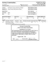
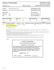
41 22 13.13-002 Bp 6 TPS Bridge Crane - Returned Revise Resubmit
41 22 13.13-002 Bp 6 TPS Bridge Crane - Returned Revise Resubmit
41 22 13.13-002 Bp 6 TPS Bridge Crane - Returned Revise Resubmit
You also want an ePaper? Increase the reach of your titles
YUMPU automatically turns print PDFs into web optimized ePapers that Google loves.
Garney Construction<br />
785 E Warren<br />
Gardner, KS 66030<br />
Phone: 816-278-5950<br />
Fax: 816-278-5931<br />
SUBMITTAL ITEM<br />
O. <strong>41</strong> <strong>22</strong><strong>13.13</strong>-<strong>002</strong><br />
PACKAGE O: <strong>41</strong> <strong>22</strong><strong>13.13</strong><br />
TITLE:<br />
PROJECT:<br />
DRAWIG:<br />
STATUS:<br />
BIC:<br />
<strong>Bp</strong> 6 <strong>TPS</strong> <strong>Bridge</strong> <strong>Crane</strong><br />
Ward County Pump Station Project<br />
R&R<br />
KC<br />
REQUIRED START:<br />
REQUIRED FIISH:<br />
DAYS HELD: 0<br />
DAYS ELAPSED: 18<br />
DAYS OVERDUE: 0<br />
RECEIVED FROM<br />
KC DOP<br />
SET TO<br />
FNI<br />
NL<br />
RETURED BY<br />
FNI NL<br />
FORWARDED TO<br />
KC DOP<br />
Revision<br />
o. Description / Remarks Received Sent <strong>Returned</strong> Forwarded Status Sepias Prints<br />
Drawing<br />
Date HeldElapsed<br />
001 <strong>Bp</strong> 6 <strong>TPS</strong> <strong>Bridge</strong> <strong>Crane</strong> 5/21/2012 5/<strong>22</strong>/2012 6/8/2012 6/8/2012 R&R 0 0 0 18<br />
Dan,<br />
This is a copy of your returned bridge crane submittal for the Ward County Transmission Pump Station. It has been returned<br />
for corrections. Please provide the following for a resubmittal:<br />
Rebecca Sandoval's Review:<br />
Refer to James Johnson for additional comments.<br />
1. Not Approved. Provide Additional Information. <strong>Revise</strong> and <strong>Resubmit</strong>.<br />
2. Provide data sheets for miscellaneous equipment (disconnect, cable, pushbutton station, etc.) as indicated in section <strong>41</strong> <strong>22</strong><br />
<strong>13.13</strong>-1, 1.03.A.1.c. Data sheets shall clearly indicate the model number being provided.<br />
3. Provide motor cut sheets. Data sheets shall clearly indicate the model number being provided.<br />
4. Motors shall be rated for 30 minute duty.<br />
James Johnson's Review:<br />
1) Not approved<br />
2) Verify hoist can lift from 2645.0' to 2680.3'<br />
3) Can hoisting speed of 15/45 fpm be provided. If not then the lower range shown is acceptable.<br />
4) Trolley traversing speed of 65 fpm is to fast. Provide 15/45 fpm 2-speed or variable speed.<br />
5) <strong>Bridge</strong> traversing speed of 100 fpm is to fast. Provide 15/45 fpm 2-speed or variable speed.<br />
6) Add Service Platform/Catwalk. It shall be lcoated along the full length of the drive girder on the opposite side the bridge<br />
festoon. The platform shall have safety rails and shall provide easy access to control panels, grease fittings, trolleys, hoist,<br />
motors, etc. The service platform shall be located on the side of the bridge that faces the electrical room and the bridge<br />
access platform. Coordinate the height of the platform with the bridge access platform.<br />
Thanks,<br />
Expedition ®<br />
Garney Construction<br />
Ward County Pump Station Project<br />
Submittal o. <strong>41</strong> <strong>22</strong><strong>13.13</strong>-<strong>002</strong><br />
This submittal has been reviewed and approved with respect to<br />
the contract documents and specification section<strong>41</strong> <strong>22</strong><strong>13.13</strong><br />
Approval or acceptance of the submittal does not relieve the<br />
vendor of their responsibility to comply with the contract<br />
documents.<br />
Supplier/Sub: KC
Garney Construction<br />
785 E Warren<br />
Gardner, KS 66030<br />
Phone: 816-278-5950<br />
Fax: 816-278-5931<br />
SUBMITTAL ITEM<br />
O. <strong>41</strong> <strong>22</strong><strong>13.13</strong>-<strong>002</strong><br />
PACKAGE O: <strong>41</strong> <strong>22</strong><strong>13.13</strong><br />
TITLE:<br />
PROJECT:<br />
DRAWIG:<br />
STATUS:<br />
BIC:<br />
<strong>Bp</strong> 6 <strong>TPS</strong> <strong>Bridge</strong> <strong>Crane</strong><br />
Ward County Pump Station Project<br />
OPN<br />
FNI<br />
REQUIRED START:<br />
REQUIRED FIISH:<br />
DAYS HELD: 0<br />
DAYS ELAPSED: 1<br />
DAYS OVERDUE: 0<br />
RECEIVED FROM<br />
KC DOP<br />
SET TO<br />
FNI<br />
NL<br />
RETURED BY<br />
FNI NL<br />
FORWARDED TO<br />
KC DOP<br />
Revision<br />
o. Description / Remarks Received Sent <strong>Returned</strong> Forwarded Status Sepias Prints<br />
Drawing<br />
Date HeldElapsed<br />
001 <strong>Bp</strong> 6 <strong>TPS</strong> <strong>Bridge</strong> <strong>Crane</strong> 5/21/2012 5/<strong>22</strong>/2012 OPN 0 0 0 1<br />
Please mark submittal RUSH.<br />
To whom it may concern:<br />
This submittal contains information and shop drawings pertaining to specification section <strong>41</strong> <strong>22</strong> <strong>13.13</strong>, <strong>Bridge</strong> <strong>Crane</strong>s.<br />
Please note:<br />
1. This submittal contains the crane components, shop drawings, and electrical components, but the electrical and control<br />
wiring schematics will be submitted under a separate cover at a later date.<br />
2. Factory test will be followed per section <strong>41</strong> <strong>22</strong> <strong>13.13</strong>-1.02.C<br />
3. Manufacturer's Representative for Startup and Testing will be provided per section <strong>41</strong> <strong>22</strong> <strong>13.13</strong>-1.02.D.<br />
If you have any questions or need any additional information please contact Luke Messer at 816-536-7187.<br />
Thanks,<br />
Garney Construction<br />
Ward County Pump Station Project<br />
Submittal o. <strong>41</strong> <strong>22</strong><strong>13.13</strong>-<strong>002</strong><br />
This submittal has been reviewed and approved with respect to<br />
the contract documents and specification section<strong>41</strong> <strong>22</strong><strong>13.13</strong><br />
Approval or acceptance of the submittal does not relieve the<br />
vendor of their responsibility to comply with the contract<br />
documents.<br />
Supplier/Sub: KC<br />
Date: ______________ Reviewed by: _________________<br />
Expedition ®
Calculation number:<br />
DO120<strong>41</strong>702<br />
Printed by .................... PRGDOP<br />
Printing date: ............. 05/<strong>22</strong>/2012<br />
Printing time: ............ 7:33 AM Page: 1 (2)<br />
CRANE DATA<br />
1 General<br />
<strong>Crane</strong> type ..............................................................................CXTD20-TON x 39ft Hol:25.77ft<br />
Span ..........................................................................................39'-0"<br />
<strong>Crane</strong> load (SWL) ...............................................................40 000 lbs<br />
Number of hoists ................................................................1 pc<br />
Hoist 1<br />
Trolley type ........................................................................Standard<br />
Hoist load ..........................................................................40 000 lbs<br />
Hoisting height .............................................................25'-9 1/8" [max 36'-1 1/16" ]<br />
Hoist type .........................................................................CXT60<strong>41</strong>0200P74FED0F<br />
Hoist group ......................................................................FEM M4 (1Am)<br />
Hoisting speed ..............................................................19/3.3 ft/min 2 - speed<br />
Trolley traversing speed ..............................................65 ft/min Stepless<br />
Weight of one hoist and trolley ..............................3 030 lbs<br />
Trolley rail gauge...............................................................5'-6 15/16"<br />
<strong>Crane</strong> use ................................................................................Indoor<br />
<strong>Crane</strong> group ...........................................................................CMAA C<br />
<strong>Bridge</strong> traveling group .....................................................FEM M5 (2m)<br />
<strong>Bridge</strong> traveling speed......................................................100 ft/min<br />
Stepless<br />
Dynamic coefficient for load .......................................1.15<br />
Dynamic coefficient dead load ...................................1.10<br />
<strong>Crane</strong> acceleration time..................................................4.7 s<br />
Weight of crane (with hoists) .......................................14 280 lbs<br />
Weight of crane bridge (without hoists) .................11 250 lbs<br />
Weight of one end carriage ...........................................790 lbs<br />
Weight of one crane traveling machinery .............40 lbs<br />
Weight of bridge panel ....................................................60 lbs<br />
Weight of one main girder ............................................4 430 lbs<br />
Weight of crane service platform ................................N/A<br />
Note! The maximum current of crane includes the starting current of hoisting motor(s)<br />
and nominal current of trolley and bridge traveling motors. The nominal current of<br />
crane includes the nominal current of hoisting, trolley and bridge motors. Maximum or<br />
nominal currents of crane do not include the currents of additional accessories, such as<br />
lamps, magnets etc.
Calculation number:<br />
DO120<strong>41</strong>702<br />
Printed by .................... PRGDOP<br />
Printing date: ............. 05/<strong>22</strong>/2012<br />
Printing time: ............ 7:33 AM Page: 2 (2)<br />
Main girder type (Profile) .............................................W24x104-MatA572<br />
Service platform type........................................................N/A<br />
Surface preparation / painting type ........................Standard / RAL1028<br />
2 Electrical<br />
Main voltage .........................................................................460 V /60 Hz<br />
Control voltage .....................................................................115 V<br />
Nominal power of crane .................................................32.2 hp<br />
Main fuse size at bridge panel ...................................60 A<br />
Maximum current of crane *) ........................................215.2 A<br />
Nominal current of crane *) ...........................................46.2 A<br />
Power factor at starting current .................................0.55<br />
Power factor at nominal current ...............................0.92<br />
Note! The maximum current of crane includes the starting current of hoisting motor(s)<br />
and nominal current of trolley and bridge traveling motors. The nominal current of<br />
crane includes the nominal current of hoisting, trolley and bridge motors. Maximum or<br />
nominal currents of crane do not include the currents of additional accessories, such as<br />
lamps, magnets etc.
Calculation number:<br />
DO120<strong>41</strong>702<br />
Printed by .................... PRGDOP<br />
Printing date: ............. 05/<strong>22</strong>/2012<br />
Printing time: ............ 7:33 AM Page: 1 (2)<br />
COMPONENTS AND ADDITIONAL FEATURES DATA<br />
1 Selected components and additional features<br />
(Included in the component package)<br />
Electric hoist 1: 1 x CXT60<strong>41</strong>0200P74FED0F<br />
- 1 pcs Overload protector (HS03)<br />
- 1 pcs Drum brake (HS07); STD<br />
- 1 pcs Mechanical overload device (LOA08)<br />
- 1 pcs Trolley travel inverter braking resistor type (FC02); STD<br />
End Carriages: 2 x ECN20B1264SL<strong>41</strong>180B0552-N<br />
- Joint: P-TOP-L_-STD-S<br />
- Buffer: D<strong>22</strong>40<br />
- 1 pcs End carriages with primer paint only (PAI05); S<br />
Traveling machinery: 2 x GES472PS3BOF06LB200-6460N<br />
<strong>Bridge</strong> panel: 1 x CRANELP7-1QM400-76JE<br />
- 1 pcs 2-step limit switch, bridge traveling (slow+stop) (LIM12); YES<br />
- 1 pcs Stainless steel bridge control panel (PAN04)<br />
- 1 pcs <strong>Bridge</strong> travel inverter braking resistor type (FC03); DMHR01F90<br />
Trolley speed control (Hoist 1): 1 x DYNADRIVE0<strong>22</strong>FXXTNS<br />
<strong>Bridge</strong> speed control: 1 x DYNAMOVE3-<strong>002</strong>FTXXB0S<br />
Trolley power supply [- festoon] package: 1 x QQSMD14M60P776119-<br />
- 1 pcs Sticker set (ST09); 4<br />
- 1 pcs Length of hoist cable free end to bridge panel(E1) (PS<strong>22</strong>); 7200<br />
- 1 pcs Length of hoist cable free end to hoist panel (E2) (PS23); 6200<br />
-AddNam (AddLm_Cod); AddFeaSubVar<br />
Push button station: 1 x PENDAX08-<strong>22</strong>21NC00-076P0
Calculation number: ... DO120<strong>41</strong>702<br />
Printed by ...................... PRGDOP<br />
Printing date: ................ 05/<strong>22</strong>/2012<br />
Printing time: ................. 7:33 AM Page: 2 (2)<br />
- 1 pcs Plug-in connector for pendant cable (ELE16); PE3<br />
2 NOT selected components<br />
(NOT included in the component package)<br />
3 Local additional features<br />
(Supplied locally. NOT included in the component package)
Calculation number:<br />
DO120<strong>41</strong>702<br />
Printed by .................... PRGDOP<br />
Printing date: ............. 05/<strong>22</strong>/2012<br />
Printing time: ............ 7:32 AM Page: 1 (2)<br />
CRANE WHEEL LOAD DATA<br />
1 Wheel load drawing<br />
2 <strong>Crane</strong> information<br />
<strong>Crane</strong> type CXTD20-TON x 39ft Buffer type<br />
D<strong>22</strong>40<br />
Hol:25.77ft<br />
Span (Spa) 39'-0" Wheel base (Wb) 9'-8 1/4"<br />
Load (SWL) 40 000 lbs <strong>Crane</strong> rail in calculati ASCE40<br />
<strong>Crane</strong> group CMAA C Wheel groove 2 1/2"<br />
<strong>Crane</strong> speed 100 ft/min Guide Rol – wheel Dis 0"<br />
Note! The inertia forces are acting on the crane structure only during acceleration<br />
and deceleration of the crane movement. Inertia forces and guiding forces do not act<br />
simultaneously. Guiding force S can also locate in wheel NR4.
Calculation number:<br />
DO120<strong>41</strong>702<br />
Printed by .................... PRGDOP<br />
Printing date: ............. 05/<strong>22</strong>/2012<br />
Printing time: ............ 7:32 AM Page: 2 (2)<br />
<strong>Crane</strong> weight 14 280 lbs <strong>Crane</strong> travel limit switc2-step<br />
3 Hoist information<br />
Hoist Hoist type Hoist group Hoisting speed<br />
Hoist 1 Main CXT60<strong>41</strong>0200P7 FEM M4 (1Am) 19/3.3 ft/min<br />
Hoist 1 Aux<br />
4 Vertical wheel loads<br />
Wheel NR1 NR2 NR3 NR4 NR5 NR6 NR7 NR8<br />
Rmax 10.6 10.0 - - 11.9 12.9 - -<br />
Stc<br />
kips kips<br />
kips kips<br />
Rmin Stc - - 2.1 kips 2.1 kips - - 2.2 kips 2.3 kips<br />
Rmax 12.1 11.4 - - 13.6 14.8 - -<br />
Dyn<br />
kips kips<br />
kips kips<br />
Rmin<br />
Dyn<br />
- - 2.4 kips 2.3 kips - - 2.5 kips 2.6 kips<br />
5 Horizontal wheel loads (according to DIN <strong>41</strong>32 + 15018 and FEM)<br />
5.1 Inertia forces (from driving mechanism HM2 = 1.6 kips<br />
5.2 Max. Wheel loads along each crane runway Kr = 0.7 kips<br />
5.3 Buffer force for dimensioning the crane runway end stopBf = 9 kips<br />
5.4 Forces coming from skewing<br />
5.4.1 Guiding (contact) force (S= HS2 +….+HS8) S = 5.0 kips<br />
5.4.2 Friction forces due to oblique travel<br />
Wheel NR1 NR2 NR3 NR4 NR5 NR6 NR7 NR8<br />
HSNR=<br />
kips<br />
1.4 3.1 0.3 0.6 -1 0.7 -0.2 0.1<br />
Note! The inertia forces are acting on the crane structure only during acceleration<br />
and deceleration of the crane movement. Inertia forces and guiding forces do not act<br />
simultaneously. Guiding force S can also locate in wheel NR4.
Calculation number:<br />
DO120<strong>41</strong>702<br />
Printed by .................... PRGDOP<br />
Printing date: ............. 05/<strong>22</strong>/2012<br />
Printing time: ............ 7:31 AM Page: 1 (2)<br />
TROLLEY WHEEL LOAD DATA<br />
Hoist 1<br />
1 General<br />
Hoist load (SWL) ................................................................40 000 lbs<br />
Hoisting height .................................................................25'-9 1/8" [max 36'-1 1/16" ]<br />
Hoist type .............................................................................CXT60<strong>41</strong>0200P74FED0F<br />
Hoist group .........................................................................FEM M4 (1Am)<br />
Trolley traversing duty group ......................................FEM M5 (2m)<br />
Hoisting speed ...................................................................19/3.3 ft/min 2-speed<br />
Trolley traversing speed ..................................................65 ft/min Stepless<br />
Weight of hoist and trolley ...........................................3 030 lbs<br />
2 Wheel load drawing<br />
3 Wheel load data<br />
Distance between wheel centers (L15).....................4'-11"<br />
Trolley rail gauge (Gau__)..............................................5'-6 15/16"
Calculation number:<br />
DO120<strong>41</strong>702<br />
Printed by .................... PRGDOP<br />
Printing date: ............. 05/<strong>22</strong>/2012<br />
Printing time: ............ 7:31 AM Page: 2 (2)<br />
Static Wheel load (load + trolley / trolley only) (NR1) 12 096 lbs / 887<br />
lbs<br />
Static Wheel load (load + trolley / trolley only) (NR2) 11 903 lbs / 546<br />
lbs<br />
Static Wheel load (load + trolley / trolley only) (NR3) 9 591 lbs / 986 lbs<br />
Static Wheel load (load + trolley / trolley only) (NR4) 9 438 lbs / 607 lbs<br />
Dynamic Wheel load (load and trolley wgt.) (NR1) 13.9 kips<br />
Dynamic Wheel load (load and trolley wgt.) (NR2) 13.7 kips<br />
Dynamic Wheel load (load and trolley wgt.) (NR3) 11.0 kips<br />
Dynamic Wheel load (load and trolley wgt.) (NR4) 10.8 kips
Calculation number:<br />
DO120<strong>41</strong>702<br />
Printed by .................... PRGDOP<br />
Printing date: ............. 05/<strong>22</strong>/2012<br />
Printing time: ............ 7:32 AM Page: 1 (2)<br />
ELECTRICAL COMPONENT DATA<br />
1 General<br />
<strong>Crane</strong> type ..............................................................................CXTD20-TON x 39ft Hol:25.77ft<br />
<strong>Crane</strong> main / control voltage.......................................460 V /60 Hz / Control 115 V<br />
Nominal power of crane .................................................32.2 hp<br />
Maximum / nominal current of crane *) ................215.2 A / 46.2 A<br />
Power factor at starting / nominal current .........0.55 / 0.92<br />
2 <strong>Bridge</strong> panel<br />
<strong>Bridge</strong> panel type ...............................................................CRANELP7-1QM400-76JE<br />
<strong>Bridge</strong> panel length / weight (preliminary)........3'-11" / 60 lbs<br />
Main fuse size at bridge panel ...................................60 A<br />
3 Hoist speed control<br />
Hoist 1<br />
Type MAIN.........................................................................2 – speed<br />
Control method / Location .........................................2SP / Trolley panel<br />
4 Trolley speed control<br />
Hoist 1<br />
Type ........................................................................................DYNADRIVE0<strong>22</strong>FXXTNS, stepless<br />
Control method / Location .........................................EP / Trolley panel<br />
Adjusted acceleration time .........................................3.6 s<br />
Nominal current margin ............................................1.4<br />
Maximum current margin .........................................1.1<br />
5 <strong>Bridge</strong> speed control<br />
Type ...........................................................................................DYNAMOVE3-<strong>002</strong>FTXXB0S, stepless<br />
Voltage ......................................................................................460 V<br />
Control method / Location ............................................EP / <strong>Bridge</strong> panel<br />
Adjusted acceleration time ............................................5.2 s<br />
Nominal current margin ...............................................1.1<br />
Maximum current margin ...........................................1.1
Calculation number:<br />
DO120<strong>41</strong>702<br />
Printed by .................... PRGDOP<br />
Printing date: ............. 05/<strong>22</strong>/2012<br />
Printing time: ............ 7:32 AM Page: 2 (2)<br />
6 Trolley power supply [festoon]<br />
Hoist 1<br />
Type ........................................................................................QQSMD14M60P776119-<br />
Hoist main power cable type .....................................FC0604 FLAT<br />
Distance between cable trolleys ...............................6'-0"<br />
Cable trolley type ............................................................KC-023571<br />
Free cable length at bridge panel end .................23'-7"<br />
Free cable length at hoist panel end ....................20'-4"<br />
Voltage drop of trolley power supply ....................
Calculation number:<br />
DO120<strong>41</strong>702<br />
Printed by .................... PRGDOP<br />
Printing date: ............. 05/<strong>22</strong>/2012<br />
Printing time: ............ 7:31 AM Page: 1 (2)<br />
MOTOR DATA<br />
1 General<br />
<strong>Crane</strong> type ..............................................................................CXTD20-TON x 39ft Hol:25.77ft<br />
Span ..........................................................................................39'-0"<br />
<strong>Crane</strong> load (SWL) ...............................................................40 000 lbs<br />
<strong>Crane</strong> voltage ........................................................................460 V<br />
2 Hoisting motor<br />
Hoist 1<br />
Motor code .......................................................................P7<br />
Motor type ........................................................................1 x MF13X-106<br />
Synchronized speed ....................................................3 600 / 600 r/min<br />
Duty group ......................................................................FEM M4 (1Am)<br />
Nominal power .............................................................28.2/4.7 hp<br />
Duty factor ......................................................................60 % ED<br />
Starting torque (High Speed) ..................................84.1 lbf-ft<br />
Starting current (High Speed) ................................207.0 A<br />
Nominal current (High Speed) ..............................38.0 A<br />
Power factor at starting current ...........................0.55<br />
Power factor at nominal current .........................0.92<br />
3 Trolley traversing motor<br />
Hoist 1<br />
Motor type ...........................................................................MF06LA20P<br />
Motor voltage .....................................................................264 V<br />
Number of motors ............................................................2 ps<br />
Synchronized speed .......................................................1 800 / r/min<br />
Nominal speed ..................................................................1 830 / r/min<br />
Duty group ..........................................................................FEM M5 (2m)<br />
Nominal power ................................................................0.5 hp<br />
Duty factor .........................................................................40 % ED<br />
Starting torque (High Speed) .....................................5.2 lbf-ft<br />
Starting current (High Speed) ...................................3.4 A<br />
Note! The supplied motor data plates have typically power and current values labeled<br />
for 40%ED (S3) use and hoisting motor for FEM M4 (1Am) duty. Therefore the data plate<br />
values might vary from the above-calculated actual values, which are based on the<br />
actual use and duty group of the crane.
Calculation number:<br />
DO120<strong>41</strong>702<br />
Printed by .................... PRGDOP<br />
Printing date: ............. 05/<strong>22</strong>/2012<br />
Printing time: ............ 7:31 AM Page: 2 (2)<br />
Nominal current (High Speed) .................................1.9 A<br />
4 <strong>Bridge</strong> traveling motor<br />
Motor type ................................................................................... MF06LB200<br />
Motor voltage.............................................................................. 460 V<br />
Number of motors .................................................................... 2 ps<br />
Synchronized speed ............................................................... 3 600 / r/min<br />
Nominal speed .......................................................................... 3 370 / r/min<br />
Duty group .................................................................................. FEM M5 (2m)<br />
Nominal power ......................................................................... 1.5 hp<br />
Duty factor .................................................................................. 40 % ED<br />
Starting torque (High Speed) ............................................. 7.7 lbf-ft<br />
Starting current (High Speed) ........................................... 3.4 A<br />
Nominal current (High Speed) ......................................... 2.2 A<br />
Note! The supplied motor data plates have typically power and current values labeled<br />
for 40%ED (S3) use and hoisting motor for FEM M4 (1Am) duty. Therefore the data plate<br />
values might vary from the above-calculated actual values, which are based on the<br />
actual use and duty group of the crane.
Calculation number:<br />
DO120<strong>41</strong>702<br />
Printed by .................... PRGDOP<br />
Printing date: ............. 05/<strong>22</strong>/2012<br />
Printing time: ............ 7:32 AM Page: 1 (2)<br />
END CARRIAGE AND TRAVELING MACHINERY DATA<br />
1 General<br />
<strong>Crane</strong> type ..............................................................................CXTD20-TON x 39ft Hol:25.77ft<br />
Span ..........................................................................................39'-0"<br />
<strong>Crane</strong> load (SWL) ...............................................................40 000 lbs<br />
2 End carriage<br />
End carriage type ...............................................................ECN20B1264SL<strong>41</strong>180B0552-N<br />
<strong>Bridge</strong> traveling group .....................................................FEM M5 (2m)<br />
Maximum static wheel load ........................................12.9 kips<br />
Maximum dynamic wheel load .................................14.8 kips<br />
Maximum wheel load along rail ..............................0.7 kips<br />
CMAA Equivalent durability wheel load - Pe ..9 162 lbs<br />
CMAA Guide for max. durability wheel load - P 13 133 lbs > Pe<br />
Wheel Hardness ...................................................................280.0 BHN<br />
Runway rail type ..............................................................ASCE40<br />
Minimum allowed wheel diameter ..........................7 1/16"<br />
Calculated bearing life time ........................................71 950 h<br />
Bending stress of end carriage .....................................8.7 ksi<br />
Deflection of end carriage .............................................0"<br />
Wheel groove .........................................................................2 1/2"<br />
Joint type ...............................................................................P-TOP-L_-STD-S<br />
Buffer type .............................................................................D<strong>22</strong>40<br />
Buffer length ........................................................................2 5/8"<br />
Buffer diameter ...................................................................3 1/8"<br />
Buffer center from top of crane rail .........................5 7/8"<br />
3 Traveling machinery<br />
Machinery type ...................................................................GES472PS3BOF06LB200-6460N<br />
Number of traveling machinery ................................2 pc<br />
Nominal power of motor (High / Low Speed) ......1.5 hp
Calculation number:<br />
DO120<strong>41</strong>702<br />
Printed by .................... PRGDOP<br />
Printing date: ............. 05/<strong>22</strong>/2012<br />
Printing time: ............ 7:32 AM Page: 2 (2)<br />
Synchronized speed of motor (High / Low Speed) 3 600 / r/min<br />
Nominal speed of motor (High / Low Speed) .......3 370 / r/min<br />
Nominal torque of motor (High Speed) ...................2.3 lbf-ft<br />
Gear ratio ...............................................................................72.8<br />
Nominal bridge speed (High / Low Speed)............100 ft/min<br />
Practical bridge speed (High Speed) .........................99.0 ft/min<br />
Stepless<br />
Acceleration time ...............................................................5.2 s (< 4.7 s)<br />
Electrical braking distance ..........................................5'-1 1/4"<br />
Mechanical braking distance ......................................2'-0"<br />
Thermal loading per motor ..........................................0.81 hp<br />
Number of starts per hour .............................................N/A<br />
Torque margin .....................................................................1.52 (>=1)<br />
Power margin .......................................................................1.82 (>=1)
Calculation number:<br />
DO120<strong>41</strong>702<br />
Printed by .................... PRGDOP<br />
Printing date: ............. 05/<strong>22</strong>/2012<br />
Printing time: ............ 7:32 AM Page: 1 (5)<br />
MAIN GIRDER DATA<br />
1 Main girder data<br />
<strong>Crane</strong> type ..............................................................................CXTD20-TON x 39ft Hol:25.77ft<br />
Main girder type code (Profile) ..................................W24x104-MatA572<br />
Flange width (B__)..............................................................1'-3/4"<br />
Girder height (H__) ............................................................2'-1/16"<br />
Thickness of web (T1_) ....................................................1/2" (Material: 50.0 ksi)<br />
Thickness of bottom flange (T2_)................................3/4" (Material: 50.0 ksi)<br />
Thickness of top flange (T4_)........................................3/4" (Material: 50.0 ksi)<br />
Actual web height at girder end (JoiMinWebHgtT1_) 1'-11 5/16"<br />
Min. web height at girder end (MinWebHgt) .......4 5/16"<br />
Trolley rail type (item 10) ............................................2"x1"<br />
Trolley end stop distance from runway rail center Panel s.: 0" / Non panel s.:<br />
3/16"<br />
2 Main girder dimensions<br />
Note! The shape of girder end is not to scale and not according to crane layout.
Calculation number:<br />
DO120<strong>41</strong>702<br />
Printed by .................... PRGDOP<br />
Printing date: ............. 05/<strong>22</strong>/2012<br />
Printing time: ............ 7:32 AM Page: 2 (5)<br />
3 Main girder welding<br />
Main girder welding ........................................................CSW01_1B1 – standard crane welding<br />
Trolley rail welding .........................................................Step weld - Indoor use<br />
4 Main girder (and service platform) weights and area<br />
Number or main girders .................................................2 ps<br />
Weight or one main girder / length unit ..............112 lbs/ft<br />
Weight of one main girder ............................................4 430 lbs<br />
Weight of crane service platform ................................N/A<br />
Service platform type........................................................N/A<br />
Surface area of main girder .........................................760 ft²<br />
Surface area of crane service platform ...................N/A<br />
5 Calculated values<br />
Vertical deflection (load and trolley) ......................15/32" < 17/32"<br />
Vertical deflection (overall)..........................................17/32" < 1 13/32"<br />
Horizontal deflection .......................................................1/16" < 15/16"<br />
Vertical frequency without load ................................10.91 > 2.00 Hz<br />
Vertical frequency with load .......................................4.31 > 2.47 Hz<br />
Horizontal frequency .......................................................4.2 > 1.80 Hz<br />
Max allowed buffer force ...............................................37.0 kips<br />
Lateral buckling factor ...................................................0.90
Calculation number:<br />
DO120<strong>41</strong>702<br />
Printed by .................... PRGDOP<br />
Printing date: ............. 05/<strong>22</strong>/2012<br />
Printing time: ............ 7:32 AM Page: 3 (5)<br />
Note! The surface areas include the multipliers for painting wastage (i.e. the<br />
area is not actual area if the wastage multiplier is not =1). The surface area of<br />
main girder includes the area of end carriages.
Calculation number:<br />
DO120<strong>41</strong>702<br />
Printed by .................... PRGDOP<br />
Printing date: ............. 05/<strong>22</strong>/2012<br />
Printing time: ............ 7:32 AM Page: 4 (5)<br />
6 Calculated values<br />
<strong>Crane</strong> type ..............................................................................CXTD20-TON x 39ft Hol:25.77ft<br />
Main girder type code (Profile) ..................................W24x104-MatA572<br />
Points Normal Shear Flange X Flange Z Equivalen Allowed Eq.<br />
t<br />
1 -12.4 0 12.4 30.0<br />
2 11.6 0 11.6 30.0<br />
3 11.5 0 11.5 30.0<br />
4 -9.6 0 9.6 30.0<br />
5 -10 -1.2 -6.5 10.1 30.0<br />
6 11.5 -1.2 11.5 30.0<br />
7<br />
8<br />
All values in ksi<br />
7 Stress calculation points<br />
Single Girder<br />
PROFILE<br />
Double<br />
Girder<br />
Single<br />
Girder<br />
BOX<br />
Double<br />
Girder<br />
BOX
Calculation number:<br />
DO120<strong>41</strong>702<br />
Printed by .................... PRGDOP<br />
Printing date: ............. 05/<strong>22</strong>/2012<br />
Printing time: ............ 7:32 AM Page: 5 (5)
CLDB01B2<br />
LOWEST POINT OF ROOF OR OTHER EQUIPMENT (LIGHTS...)<br />
11’-2 1/8" 31’-1 1/8"<br />
5’-7 1/8"<br />
5’-3 1/8"<br />
9’-8 1/4"<br />
25’-6"<br />
5’-6 7/8"<br />
3’-2 1/4"<br />
Min. 8"<br />
26’-7 1/4" 2’-1"<br />
A<br />
A<br />
3’-3"<br />
25’-5"<br />
CXT60<strong>41</strong>0200P7<br />
CABLE CHANNEL<br />
5’-0" 4"<br />
25’-9 1/8"<br />
Min. 2"<br />
Min. 1 1/8"<br />
20 Ton<br />
Min. 3’-0" Min. 3’-0"<br />
39’-0"<br />
Max. 1’-1 3/4"<br />
RAIL ASCE40<br />
Max. 5 7/8"<br />
3’-4 7/8"<br />
Min. 8"<br />
RAIL ASCE40<br />
MAX. STATIC WHEEL LOAD 12.9 kips<br />
3’-11 1/4"<br />
1’-9 3/4"<br />
3’-11 1/4"<br />
ECN20B1264SL<strong>41</strong>180B0552-N<br />
INDICATE NORTH DIRECTION<br />
IMPORTANT<br />
TECHNICAL DATA<br />
MODIFY, IF REQUIRED, AND APPROVE ONE<br />
SET OF PRINTS AND RETURN WITHIN TWO<br />
WEEKS OF DRAWING DATE. ANY DELAY IN<br />
RETURNING AN APPROVED PRINT MAY MEAN<br />
A DELAY IN SHIPMENT.<br />
APPROVED______________________<br />
BY____________________________<br />
DATE__________________________<br />
= =<br />
LOAD........................................<br />
SPAN........................................<br />
LIFTING HEIGHT.....................<br />
HOISTING SPEED...................<br />
TROLLEY SPEED....................<br />
BRIDGE SPEED......................<br />
WEIGHT OF TROLLEY............<br />
WEIGHT OF BRIDGE..............<br />
POWER SUPPLY.....................<br />
CRANE GROUP.......................<br />
PART LIST<br />
A-A<br />
4"<br />
4"<br />
2’-4"<br />
3 1/4"<br />
20 Ton<br />
39’-0"<br />
25’-9 1/8"<br />
19/3.3 ft/min 2-SPEED<br />
65 ft/min STEPLESS<br />
100 ft/min STEPLESS<br />
3030 lbs<br />
11250 lbs<br />
460 V / 115 V / 60 Hz<br />
CMAA C<br />
5 7/8"<br />
39’-9 5/8"<br />
CUSTOMER ORGANIZES SAFE<br />
PLATFORM FOR CRANE SERVICE<br />
DRAWING NOT IN SCALE<br />
DOP/PRG<br />
4/17/2012 20 Ton CXTD <strong>Crane</strong><br />
20 Ton <strong>Crane</strong> (<strong>TPS</strong>)<br />
DO120<strong>41</strong>702
SPARE PART CATALOGUE FOR<br />
CXT PUSHBUTTON CONTROLLER<br />
Ver. 4, Modified 27/01/2004<br />
Konecranes<br />
Konecranes reserves the right to alter or amend the above information without notice. 1
Pushbutton controller<br />
Konecranes<br />
Konecranes reserves the right to alter or amend the above information without notice. 2
POS ITEM CODE DESCRIPTION SPECIFICATION PCS/<br />
PENDANT TYPE<br />
06 08 12<br />
1 5<strong>22</strong>99990 SLEEVE CABLE SLEEVE 1 1 1<br />
4 5<strong>22</strong>92954 BUTTON ESTOP 1 1 1<br />
5 5<strong>22</strong>92949 BUTTON BUTTON ON/HORN 1 1 1<br />
6 5<strong>22</strong>99970 COVER COVER-8 UPPER 1 1<br />
6 5<strong>22</strong>99974 COVER COVER-12 UPPER 1<br />
7 5<strong>22</strong>99987 COVER PLATE FOR 3+3 CONT. 1 1 2<br />
8 5<strong>22</strong>92951 CONTACT BLOCK CONTACT NC 1 1 1<br />
9 5<strong>22</strong>92950 CONTACT BLOCK CONTACT NO 2 2 2<br />
10 5<strong>22</strong>99969 COVER COVER-8 LOWER 1 1<br />
10 5<strong>22</strong>99973 COVER COVER-12 LOWER 1<br />
11 5<strong>22</strong>99962 BUTTON BUTTON ARROW BL D 2 3 3<br />
12 5<strong>22</strong>99964 BUTTON BUTTON ARROW WH D 2 3 3<br />
13 5<strong>22</strong>99959 BUTTON BUTTON RUBBER DOUBLE 2 3 3<br />
14 5<strong>22</strong>99960 PLATE BUTTON PLATE DOUBLE 2 3 3<br />
15 5<strong>22</strong>92952 CONTACT BLOCK CONTACT 2ST 2DIR 2 3 3<br />
16 5<strong>22</strong>99989 PLUG BLANKING PLUG 2 3<br />
17 52312604 PENDANT CONTROLLER PBQ06<strong>22</strong>02D00-N 1<br />
17 52312605 PENDANT CONTROLLER PBQ08<strong>22</strong><strong>22</strong>D00-N 1<br />
17 52312606 PENDANT CONTROLLER PBQ1<strong>22</strong><strong>22</strong>2DV3-N 1<br />
19 5<strong>22</strong>92955 SWITCH SELECTOR I,I+II,II 1<br />
20 52313929 CLAMP CABLE FIXING CLAMP 1 1 1<br />
ON-HORN complete consist of parts 5, 7, 9<br />
E-STOP complete consist of parts 4, 7, 8<br />
OPTIONAL PARTS:<br />
POS ITEM CODE DESCRIPTION SPECIFICATION PENDANT TYPE<br />
06 08 12<br />
1 5<strong>22</strong>99991 SLEEVE CABLE SLEEVE SILICONE X X X<br />
5 5<strong>22</strong>99965 BUTTON BUTTON RUBBER SINGLE X X X<br />
5 5<strong>22</strong>99966 BUTTON BUTTON ARROW BLS X X X<br />
5 5<strong>22</strong>99967 BUTTON BUTTON ARROW WH S X X X<br />
7 5<strong>22</strong>99986 PLATE PLATE FOR 2+2 CONT. X X X<br />
7 5<strong>22</strong>99988 PLATE PLATE FOR 3 CONT. X X X<br />
15 5<strong>22</strong>92953 CONTACT BLOCK CONTACT 1ST 2DIR X X X<br />
19 5<strong>22</strong>99952 SWITCH SELECTOR 0,1 SPR X X X<br />
19 5<strong>22</strong>99343 SWITCH SELECTOR 0,1 X X X<br />
19 5<strong>22</strong>99344 SWITCH SELECTOR 1,0,2 SPR X X X<br />
19 5<strong>22</strong>99346 SWITCH SELECTOR 0,1 KEY X X X<br />
19 5<strong>22</strong>99954 SWITCH SELECTOR 0.1 KEY SPR X X X<br />
5<strong>22</strong>98180 HOLDER LAMP HOLDER X X X<br />
5<strong>22</strong>99956 LIGHT LAMP RED X X X<br />
5<strong>22</strong>99957 LIGHT LAMP YELLOW X X X<br />
5<strong>22</strong>99958 LIGHT LAMP GREEN X X X<br />
5<strong>22</strong>92512 DISPLAY CID-DISPLAY X X X<br />
5<strong>22</strong>93292 CABLE CABLE FOR DISPLAY X X X<br />
52310637 STICKER SEN/FI X X X<br />
52311235 STICKER US/AUS X X X<br />
Konecranes<br />
Konecranes reserves the right to alter or amend the above information without notice. 3


