Residual frequency offset tracking
Residual frequency offset tracking
Residual frequency offset tracking

You also want an ePaper? Increase the reach of your titles
YUMPU automatically turns print PDFs into web optimized ePapers that Google loves.
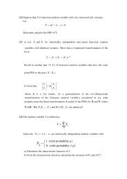
<strong>Residual</strong> <strong>frequency</strong> <strong>offset</strong> <strong>tracking</strong><br />
Po-Lin Chen ( 陳 柏 霖 )
Position in receiver<br />
After pilot estimation<br />
Carrier phase <strong>tracking</strong> [1] [2]<br />
Outline<br />
Data-aided carrier phase <strong>tracking</strong><br />
Averaging process<br />
L-extension Method<br />
Nondata-aided carrier phase <strong>tracking</strong><br />
Implementation<br />
References<br />
2004/4/29 2<br />
WLAN Group
Position in receiver<br />
Timing,<br />
<strong>frequency</strong><br />
and phase<br />
estimation<br />
Channel<br />
estimation<br />
Time &<br />
Phase<br />
phase<br />
estimation<br />
<strong>tracking</strong><br />
Frequency<br />
compensation<br />
Remove<br />
cyclic<br />
extension<br />
FFT<br />
Channel<br />
compensation<br />
Time &<br />
Phase<br />
compensation<br />
phase<br />
compensation<br />
Demapping<br />
Deinterleave<br />
Decoding<br />
Received<br />
data<br />
X(n) after A/D,AGC<br />
2004/4/29 3<br />
WLAN Group
After pilot estimation<br />
Channel compensation<br />
Pilot estimated<br />
Tracking<br />
Data symbols<br />
.*<br />
Pilot subcarriers<br />
y(n)<br />
phase<br />
<strong>tracking</strong><br />
Corrected<br />
symbols<br />
2004/4/29 4<br />
WLAN Group
Carrier phase <strong>tracking</strong><br />
Frequency estimation is not a perfect process, so there is<br />
always some residual <strong>frequency</strong> error.<br />
ICI here shouldn’t be a problem, but constellation<br />
rotation may be a main one.<br />
2004/4/29 5<br />
WLAN Group
Data-aided carrier phase <strong>tracking</strong><br />
802.11a include four predefined subcarrier, [1 1 1 -1] or<br />
[-1 -1 -1 1] , among the transmitted data.<br />
These subcarriers are referred to as pilot subcarriers.<br />
The received pilot subcarrier<br />
R<br />
n , k<br />
= H<br />
k<br />
P<br />
n , k<br />
e<br />
j 2πnf<br />
∆<br />
where n is the OFDM symbol index, k is subcarrier index,<br />
Hk is channel <strong>frequency</strong> response, Pn,k is the predefined<br />
subcarrier and is the residual <strong>frequency</strong> error.<br />
f ∆<br />
2004/4/29 6<br />
WLAN Group
Averaging process<br />
Assuming the estimate Hk for channel is perfectly<br />
accurate, we can get the estimator<br />
If not,<br />
∧<br />
Φ<br />
∧<br />
Φ<br />
n<br />
n<br />
= ∠[<br />
⎡<br />
= ∠⎢e<br />
⎣<br />
= ∠[<br />
∑<br />
R<br />
k = pilots<br />
j2πnf<br />
∑<br />
R<br />
k = pilots<br />
∆<br />
*<br />
n, k<br />
( H<br />
k<br />
Pn<br />
, k<br />
) ]<br />
n,<br />
k<br />
∑<br />
k = pilots<br />
∧<br />
( H<br />
k<br />
H<br />
P<br />
k<br />
n,<br />
k<br />
2<br />
)<br />
⎤<br />
⎥<br />
⎦<br />
*<br />
]<br />
= ∠[<br />
∑<br />
H<br />
k = pilots<br />
k<br />
P<br />
n,<br />
k<br />
e<br />
j2πnf<br />
∆<br />
∧<br />
( H<br />
k<br />
P<br />
n,<br />
k<br />
)<br />
*<br />
]<br />
2004/4/29 7<br />
WLAN Group
Averaging process<br />
For one OFDM symbol in AWGN, Sk denotes the k-th<br />
pilot signal, and W denotes the AWGN noise whose<br />
2<br />
distribution is ~N (0, σ n ). Then, the average of the four<br />
pilot signals is<br />
(S1+W + S2+W + S3+W + S4+W) / 4<br />
= (S1 + S2 + S3 + S4 + W’) / 4<br />
= Save+Wave<br />
where W’ and Wave are the new AWGN, whose<br />
2<br />
2<br />
distributions are ~N (0, 4 σ n ) and ~N (0, σ n<br />
/ 4),<br />
respectively.<br />
2004/4/29 8<br />
WLAN Group
We use the equation<br />
So, we get<br />
Averaging process<br />
var( a + bx)<br />
= b<br />
=<br />
var( W<br />
1<br />
var(<br />
4<br />
var( x)<br />
2004/4/29 9<br />
WLAN Group<br />
2<br />
ave<br />
1<br />
=<br />
16<br />
1<br />
= ⋅4σ<br />
16<br />
1 2<br />
= σ n<br />
4<br />
)<br />
W ')<br />
var( W ')<br />
2<br />
n<br />
Average makes<br />
variance smaller
L-extension Method<br />
ADPLL (All Digital Phase-Locked Loop)<br />
2004/4/29 10<br />
WLAN Group
L-extension Method<br />
Consider L = 3, pilots are extracted from symbol 1 and<br />
held in the register. When symbol 3 arrives, error phase<br />
detector will calculate the error phases between the same<br />
pilots of the symbols and take the average of them.<br />
The result will be fed into the ADPLL to generate an<br />
proper <strong>frequency</strong> to compensate the <strong>frequency</strong> <strong>offset</strong> of<br />
symbols 4, 5 and 6.<br />
Now, symbols 4 and 6 replace the position of symbols 1<br />
and 3, respectively.<br />
2004/4/29 11<br />
WLAN Group
L-extension Method<br />
This time the <strong>frequency</strong> <strong>offset</strong> estimation will be added<br />
to original <strong>frequency</strong> <strong>offset</strong>, i.e. accumulation.<br />
The accumulated <strong>offset</strong> is used to compensate symbols 7,<br />
8 and 9.<br />
This process continues until the end of a packet.<br />
2004/4/29 12<br />
WLAN Group
L-extension Method<br />
First, let us discuss a portion of one OFDM symbol<br />
produced after IFFT in the baseband of transmitter<br />
s ( n )<br />
N<br />
1<br />
−<br />
= ∑<br />
N<br />
1<br />
k = 0<br />
X<br />
k<br />
e<br />
j 2 πnk<br />
/<br />
N<br />
n<br />
=<br />
0,1,......,<br />
N<br />
−<br />
1<br />
where Xk is a complex value in the k-th carrier, N is the<br />
number of OFDM subcarriers, s(n) is a complex value<br />
in the n-th output carrier.<br />
2004/4/29 13<br />
WLAN Group
L-extension Method<br />
Assume that the wireless environment brings in a phase<br />
<strong>offset</strong> θ and <strong>frequency</strong> <strong>offset</strong> ∆f (after coarse and fine<br />
<strong>frequency</strong> compensation) and assume that we have the<br />
perfect symbol boundary with sampling clock T = Ts/N<br />
then<br />
j(2π∆fnT<br />
+ θ )<br />
r<br />
n<br />
=<br />
=<br />
=<br />
e<br />
e<br />
e<br />
j(2π∆fnT<br />
+ θ )<br />
jθ<br />
1<br />
N<br />
N −1<br />
∑<br />
k = 0<br />
s(<br />
n)<br />
where Ts is symbol duration and ∆k = NT∆f<br />
= ∆f<br />
/ f s<br />
is a<br />
normalized <strong>frequency</strong> <strong>offset</strong> of the carrier spacing.<br />
N −1<br />
2004/4/29 14<br />
WLAN Group<br />
X<br />
1<br />
N<br />
k<br />
e<br />
∑<br />
k = 0<br />
X<br />
k<br />
e<br />
j2πnk<br />
/ N<br />
j2πn(<br />
k +∆k<br />
)/ N
L-extension Method<br />
After FFT in the baseband of receiver,<br />
^<br />
X<br />
p<br />
=<br />
=<br />
N −1<br />
∑<br />
n=<br />
0<br />
n<br />
− j2πnp<br />
/ N<br />
N −1<br />
N −1<br />
N −1<br />
1 jθ<br />
2 /<br />
( ∑<br />
j πn∆k<br />
N<br />
e X + ∑∑<br />
ke<br />
n=<br />
0<br />
n=<br />
0 n=<br />
0, n≠<br />
p<br />
N<br />
r<br />
e<br />
X<br />
k<br />
e<br />
2πp(<br />
k − p+∆k<br />
)<br />
j<br />
N<br />
ICI (intercarrier interference)<br />
)<br />
2004/4/29 15<br />
WLAN Group
L-extension Method<br />
If the <strong>offset</strong> is small enough, the second term can be<br />
ignored. It means<br />
X<br />
^ N − 1<br />
1 jθ<br />
= ∑ p<br />
e<br />
N n=<br />
0<br />
X<br />
k<br />
e<br />
j2πn∆k<br />
/ N<br />
and the (L-1)th symbol before it is<br />
^ N<br />
− + + ∆ +<br />
− 1<br />
1 j[2π<br />
( L 1)( N N g ) T f θ ]<br />
∑ − L,<br />
p = e<br />
N<br />
n=<br />
0<br />
X<br />
j2πn∆k<br />
/ N<br />
Hence, the estimated <strong>frequency</strong> <strong>offset</strong> is given by<br />
∆<br />
^<br />
f<br />
1<br />
=<br />
2πT<br />
( L −1)(<br />
N + N<br />
2004/4/29 16<br />
WLAN Group<br />
g<br />
)<br />
(<br />
∑<br />
p=<br />
pilot<br />
^<br />
( ∠ X<br />
X<br />
p<br />
k<br />
e<br />
− ∠<br />
^<br />
X<br />
−L,<br />
p<br />
))
L-extension Method<br />
The range of<br />
−L,<br />
p<br />
then, the observation range is<br />
^<br />
∑(<br />
∠ X<br />
p=<br />
pilot<br />
p<br />
− ∠<br />
^<br />
X<br />
)<br />
is<br />
−π<br />
~ π<br />
2( N<br />
+<br />
−1<br />
N ) T ( L<br />
g<br />
−1)<br />
≤ ∆<br />
^<br />
f<br />
≤<br />
2( N<br />
+<br />
1<br />
N ) T ( L<br />
g<br />
−1)<br />
2004/4/29 17<br />
WLAN Group
L-extension Method<br />
If L is too long, the first uncompensated symbols may<br />
suffer large phase rotation and degrade the performance.<br />
2004/4/29 18<br />
WLAN Group
L-extension Method<br />
Where t1 and t2 denote the durations of different L.<br />
We can observe that large t2 cause a large phase rotation<br />
such that the constellation points exceed the demodulation<br />
range and errors take place.<br />
Therefore, it is of significance to discover an optimal L.<br />
2004/4/29 19<br />
WLAN Group
Simulation in AWGN<br />
2004/4/29 20<br />
WLAN Group
Simulation in AWGN<br />
20<br />
2004/4/29 21<br />
WLAN Group
Simulation in AWGN<br />
2004/4/29 22<br />
WLAN Group
Simulation in AWGN<br />
From above graphs, we know that the higher the mapping<br />
scheme is used, the smaller the optimal L is.<br />
At the initial state, the system isn’t able to acquire the best<br />
performance by optimizing L, hence a trade-off should be<br />
made between L and performance according<br />
to different modulation schemes.<br />
2004/4/29 23<br />
WLAN Group
Nondata-aided carrier phase <strong>tracking</strong><br />
The phase error can be estimated without pilot symbols.<br />
The phase error resulting from <strong>frequency</strong> <strong>offset</strong> is<br />
identical for subcarriers.<br />
The angle can be estimated without any knowledge of<br />
the data by performing hard decision on the received data<br />
symbol after they are corrected for the channel effect.<br />
2004/4/29 24<br />
WLAN Group
Nondata-aided carrier phase <strong>tracking</strong><br />
Here Xn,k doesn’t necessarily 1 or -1.<br />
∧<br />
Φ<br />
n<br />
= ∠[<br />
N −1<br />
∑<br />
k = 0<br />
⎡<br />
= ∠⎢e<br />
⎣<br />
R<br />
j2πnf<br />
n,<br />
k<br />
∆<br />
N −1<br />
∑<br />
k = 0<br />
^<br />
( H<br />
|<br />
k<br />
H<br />
X<br />
k<br />
^<br />
n,<br />
k<br />
|<br />
2<br />
|<br />
)<br />
*<br />
]<br />
X<br />
n,<br />
k<br />
|<br />
2<br />
⎤<br />
⎥<br />
⎦<br />
2004/4/29 25<br />
WLAN Group
Implementation<br />
2004/4/29 26<br />
WLAN Group
Table<br />
2004/4/29 27<br />
WLAN Group
Idea<br />
Replace arctan by tangent to simplify the challenge, i.e.,<br />
error_pilot_sum_Q[input_length:0] >= error_pilot_sum_I<br />
error_pilot_sum_Q[input_length:0] >= (error_pilot_sum_I>>1)<br />
error_pilot_sum_Q[input_length:0] >= (error_pilot_sum_I>>2)<br />
error_pilot_sum_Q[input_length:0] >= (error_pilot_sum_I>>3)<br />
………………….<br />
2004/4/29 28<br />
WLAN Group
References<br />
[1] John Terry and Juha Heiskala “OFDM Wireless<br />
LAN_ A Theoretical and Practical Guide.”<br />
[2] 賴 祐 徵 “Research on <strong>Residual</strong> Carrier Frequency<br />
Offset Tracking in OFDM Wireless LAN Systems”<br />
2004/4/29 29<br />
WLAN Group