
Create successful ePaper yourself
Turn your PDF publications into a flip-book with our unique Google optimized e-Paper software.
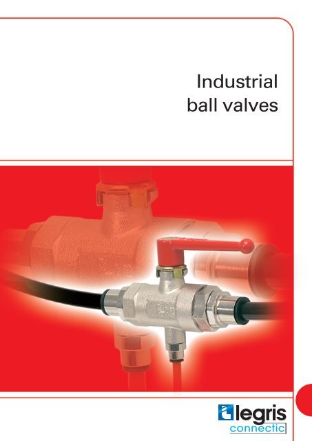
Industrial<br />
<strong>ball</strong> <strong>valves</strong>
Industrial <strong>ball</strong> <strong>valves</strong><br />
<strong>Legris</strong> provides a wide range of <strong>ball</strong> <strong>valves</strong>, adapted to many applications, and suited to a variety of customer requirements<br />
in terms of performance.<br />
Ball <strong>valves</strong><br />
Industrial series<br />
Ball <strong>valves</strong><br />
Semi-standard series<br />
● suitable for pressures up to 300 bar<br />
● excellent sealing at low and high pressure<br />
● secure non removable inlet and outlet ports<br />
● handle replaceable by a wheel<br />
● to satisfy specific customer requirements<br />
● 6 versions cover virtually all requirements for different types<br />
of fluids and applications<br />
Needle <strong>valves</strong><br />
Needle <strong>valves</strong>: accessories<br />
●<br />
compact and designed for use where a combination of fluid<br />
control and perfect sealing is required<br />
● various configurations, connection types and dimensions<br />
● needle drain <strong>valves</strong><br />
● venting pressure gauge <strong>valves</strong><br />
● pressure relief valve<br />
Axial <strong>valves</strong><br />
On pages R24 to R27, an application table enables correct<br />
choice of valve depending on the fluid used.<br />
● overcome the limitations of traditional actuators<br />
● excellent performance<br />
● compatible with numerous industrial fluids<br />
● straightforward reliable installation<br />
R2
Industrial <strong>ball</strong> <strong>valves</strong><br />
The variety of this range provides an answer to many specific requirements. Select the model required for your application.<br />
Ball <strong>valves</strong><br />
Standard range, 2 and 3 way<br />
Ball <strong>valves</strong><br />
Standard range, lockable<br />
● for all industrial applications<br />
● long life<br />
● in-line, with right angled flow and screw fixing versions<br />
● for safety of personnel and equipment<br />
● <strong>valves</strong> are lockable:<br />
- in both open and closed position<br />
- only in the closed position<br />
Ball <strong>valves</strong><br />
Standard range, vented<br />
Ball <strong>valves</strong><br />
Light series<br />
● with threaded exhaust, to allow discharge of downstream<br />
media<br />
● with pin-hole vent, for applications with no special discharge<br />
requirement<br />
● fluid flow direction<br />
Ball <strong>valves</strong><br />
Fluoropolymer series<br />
● allow the passage of many fluids<br />
● suited to medium pressures and temperatures<br />
● models with standard handle and with a square stem<br />
Ball <strong>valves</strong><br />
Stainless steel series<br />
● suitable for many applications requiring PTFE seals<br />
● both high quality and good value<br />
● H.R. range, guaranteed silicone free<br />
● economy range with standard handle and butterfly handle<br />
● designed for use with corrosive fluids<br />
● resistance to aggressive environments<br />
● with <strong>ball</strong>, one piece, ''3-piece'' and needle types<br />
R3
the complete range of <strong>ball</strong> <strong>valves</strong><br />
in-line <strong>ball</strong> <strong>valves</strong><br />
0402<br />
Page R7<br />
0401 0400<br />
Page R7<br />
Page R7<br />
0411 0414<br />
Page R7<br />
Page R7<br />
in-line with fixing holes and panel mounting<br />
right-angled <strong>ball</strong> <strong>valves</strong><br />
0446<br />
6402 6401 0472 0471<br />
Page R8<br />
Page R8<br />
Page R8<br />
Page R9<br />
Page R9<br />
in-line <strong>ball</strong> <strong>valves</strong> – 3 way<br />
0482 0483<br />
0448 0452<br />
Page R10 Page R10 Page R10 Page R10<br />
light series<br />
0492 0491 0490 0494<br />
Page R11 Page R11 Page R11 Page R11<br />
light series with square stem<br />
0497 0496<br />
Page R12<br />
Page R12<br />
lenticular <strong>valves</strong><br />
4602<br />
Page R12<br />
in-line fluoropolymer series<br />
4902 4905 4906 4900 4903 4901 4904<br />
Page R13 Page R14 Page R14 Page R15<br />
Page R15 Page R15 Page R15<br />
lockable <strong>ball</strong> <strong>valves</strong><br />
0432 0438<br />
0437<br />
0439<br />
Page R16<br />
Page R16<br />
Page R17<br />
Page R17<br />
venting <strong>ball</strong> <strong>valves</strong><br />
0489 0449 0469<br />
Page R18 Page R18 Page R18<br />
standard vented, with right angled flow<br />
0462<br />
0461<br />
Page R19<br />
Page R19<br />
high pressure <strong>ball</strong> <strong>valves</strong><br />
4402<br />
Page R20<br />
R4
the complete range of <strong>ball</strong> <strong>valves</strong><br />
stainless steel <strong>ball</strong> <strong>valves</strong><br />
4832 4812 4810<br />
Page R21 Page R21 Page R21<br />
stainless steel <strong>ball</strong> <strong>valves</strong><br />
0465<br />
Page R22<br />
needle <strong>valves</strong><br />
0502 0501<br />
0510 0532 0531<br />
Page R28 Page R28 Page R28<br />
Page R29<br />
Page R29<br />
accessories<br />
0562 0563 0627 0630<br />
Page R29<br />
Page R29 Page R29 Page R29<br />
axial <strong>valves</strong><br />
4202 4212 4222<br />
Page R32 Page R32 Page R32<br />
accessories<br />
4298 4298 4299<br />
Page R33 Page R33 Page R33<br />
Identification<br />
Part numbers have been chosen by a method of mnemonics.<br />
Each valve is identified by :<br />
● its series<br />
● the diameter of passage through the valve<br />
● the thread code<br />
type of <strong>ball</strong><br />
valve<br />
Example<br />
4902 20 27<br />
diameter of<br />
passage<br />
thread code<br />
R5
principle of <strong>ball</strong> <strong>valves</strong><br />
Standard range<br />
The standard <strong>Legris</strong> <strong>ball</strong> valve provides a reliable means of<br />
opening and closing fluid systems. It requires a simple quarter<br />
turn of the handle to operate the two-way version, or a 180°<br />
turn for the three way version.<br />
Principal advantages:<br />
● optimum sealing due to compensating "O" rings<br />
● smooth operation due to low friction coefficient of chemically<br />
nickel-plated brass<br />
● excellent resistance to scaling due to <strong>ball</strong> seal configuration<br />
● <strong>Legris</strong> <strong>ball</strong> <strong>valves</strong> provide many thousands of trouble free<br />
operations due to the "O" rings compensating for seal wear<br />
Reliability :<br />
● the <strong>ball</strong> is sealed on both sides by graphite impregnated<br />
rilsan seals which are supported by perbunan compensating<br />
“O” rings. This ensures that the seal remains in contact with<br />
the <strong>ball</strong> at all times thus extending the life of the <strong>ball</strong> valve by<br />
preventing leakage should seal wear occur.<br />
● the stem is firmly secured within a square insert on the<br />
<strong>ball</strong> and is sealed by an “O” ring.<br />
technical specifications<br />
working<br />
see application table on pages R24 to R27<br />
fluids<br />
working<br />
20 to 40 bar depending on the model<br />
Brass stem<br />
Handle<br />
retaining screw<br />
Handle<br />
pressure<br />
Perbunan 'O' ringstem<br />
seal<br />
working<br />
temperature<br />
- 20° to + 80°C<br />
Perbunan<br />
compensating<br />
"O" ring<br />
constituent materials<br />
body : sand blasted nickel-plated brass<br />
<strong>ball</strong> : polished brass<br />
Brass threaded<br />
insert<br />
stem : brass<br />
retaining nut : brass<br />
<strong>ball</strong> seal : graphite impregnated rilsan<br />
stem seal : nitrile<br />
Rilsan<br />
graphite <strong>ball</strong><br />
seals<br />
Nickelplated<br />
brass <strong>ball</strong><br />
Brass body<br />
maximum<br />
tightening torques<br />
of <strong>ball</strong> <strong>valves</strong>,<br />
compensating "O" rings : nitrile<br />
thread<br />
m.daN<br />
G1/8<br />
0,10<br />
to 0,20<br />
G1/4<br />
0,10<br />
to 0,20<br />
G3/8<br />
0,15<br />
to 0,25<br />
G1/2<br />
0,20<br />
to 0,35<br />
G3/4<br />
0,50<br />
to 0,70<br />
standard range<br />
thread<br />
G1"<br />
G1"1/4<br />
G1"1/2<br />
G2"<br />
m.daN<br />
0,50<br />
to 0,70<br />
0,40<br />
to 0,60<br />
0,80<br />
to 1,20<br />
0,80<br />
to 1,20<br />
R6
standard in-line <strong>ball</strong> <strong>valves</strong><br />
0402<br />
double female<br />
sand blasted nickel-plated<br />
brass body<br />
H<br />
F<br />
L<br />
L1<br />
M<br />
C<br />
F1<br />
H1<br />
C<br />
DN<br />
F F1 H H1<br />
G1/8 4 0402 04 10 - 14 35 29 44 25 48 0,091<br />
G1/8 7 0402 07 10 19 19 38 31 51 27 48 0,167<br />
G1/4 7 0402 07 13 19 19 38 31 53 28 48 0,157<br />
G3/8 10 0402 10 17 24 24 45 43 59 31 69 0,230<br />
G1/2 13 0402 13 21 27 27 47 44 67 34 69 0,291<br />
G3/4 20 0402 20 27 32 38 63 54 80 39 108 0,690<br />
G1“ 23 0402 23 34 41 46 67 57 94 47 108 1,030<br />
G1“1/4 32 0402 32 42* 55 60 97 105 112 59 180 2,433<br />
G1“1/2 32 0402 32 49* 55 60 97 105 120 62 180 2,278<br />
G1“1/2 40 0402 40 49* 55 55 104 105 111 55 190 2,558<br />
G2“ 40 0402 40 48* 70 70 104 105 122 61 190 2,754<br />
L<br />
L1<br />
M<br />
kg<br />
*models with CE marking<br />
maximum working pressure : 40 bar<br />
0401 male female<br />
0400 double male<br />
sand blasted nickel-plated<br />
brass body<br />
H<br />
H<br />
J<br />
J<br />
C<br />
L<br />
L1<br />
C L1<br />
L<br />
M<br />
C<br />
F<br />
F<br />
H1<br />
H1<br />
sand blasted nickel-plated<br />
brass body M<br />
C<br />
DN<br />
F H H1 J<br />
G1/8 4 0401 04 10 14 35 29 14 45 25 48 0,091<br />
G1/8 5 0401 05 10 19 38 31 19 51 27 48 0,158<br />
G1/4 7 0401 07 13 19 38 31 19 52 28 48 0,151<br />
G3/8 10 0401 10 17 24 45 43 24 58 31 69 0,227<br />
G1/2 13 0401 13 21 27 47 44 27 66 34 69 0,290<br />
G3/4 18 0401 18 27 38 63 54 39 79 39 108 0,714<br />
G1“ 23 0401 23 34 46 67 57 48 91 47 108 1,028<br />
G1“1/4 32 0401 32 42* 60 97 115 55 113 59 180 2,374<br />
*models with CE marking<br />
maximum working pressure : 40 bar<br />
C<br />
DN<br />
F H H1 J<br />
G1/8 4 0400 04 10 14 35 29 14 45 25 48 0,091<br />
G1/4 7 0400 07 13 19 38 31 19 60 36 48 0,163<br />
G3/8 10 0400 10 17 24 45 43 24 70 43 69 0,251<br />
G1/2 13 0400 13 21 27 47 44 27 78 45 69 0,327<br />
G3/4 18 0400 18 27 38 63 54 39 90 50 108 0,770<br />
maximum working pressure : 40 bar<br />
L<br />
L<br />
L1<br />
L1<br />
M<br />
M<br />
kg<br />
kg<br />
0411<br />
0414<br />
with two couplings fitted for use with steel tube<br />
sand blasted nickel-plated<br />
brass body M<br />
H<br />
øD<br />
J<br />
F<br />
L1<br />
L<br />
H1<br />
F1<br />
sand blasted nickel-plated<br />
brass body M<br />
H<br />
øD<br />
J<br />
F<br />
L1<br />
L<br />
H1<br />
F1<br />
ØD<br />
DN<br />
F F1 H H1 J<br />
6 4 0411 04 06 14 19 38 31 19 76 30 48 0,183<br />
8 6 0411 06 08 17 19 38 31 19 77 30 48 0,182<br />
10 7 0411 07 10 19 19 38 31 19 78 31 48 0,207<br />
12 10 0411 10 12 22 24 45 43 24 85 36 69 0,312<br />
maximum working pressure : 40 bar<br />
with two couplings fitted with double taper rings<br />
ØD<br />
DN<br />
F F1 H H1 J<br />
6 4 0414 04 06 13 19 38 31 19 72 31 48 0,179<br />
8 6 0414 06 08 14 19 38 31 19 74 30 48 0,181<br />
10 7 0414 07 10 19 19 38 31 19 78 31 48 0,210<br />
12 10 0414 10 12 22 24 45 43 24 86 36 69 0,305<br />
maximum working pressure : 40 bar<br />
L<br />
L<br />
L1<br />
L1<br />
M<br />
M<br />
kg<br />
kg<br />
length of female threads (E)<br />
and male BSPP threads (E1)<br />
0402 – 0401 and 0400<br />
C<br />
E1<br />
E<br />
C<br />
C G1/8 G1/4 G3/8 G1/2 G3/4 G1“ G1“1/4 G1“1/2 G2“<br />
E 8 12 12 15 16,5 19 21,5 22 26<br />
E1 7 9 11 12 12 15 18<br />
R7
standard <strong>ball</strong> <strong>valves</strong> for screw fixing and panel mounting<br />
0446<br />
6402<br />
double female - panel mounted<br />
sand blasted nickel-plated<br />
brass body<br />
M<br />
double female - screw fixing<br />
H<br />
H1<br />
F1<br />
øG<br />
F<br />
øT<br />
L1<br />
L<br />
øT<br />
L1<br />
L<br />
5 maxi*<br />
C<br />
M<br />
C<br />
H2<br />
H1<br />
sand-blasted body nickel<br />
plated-brass<br />
F<br />
H2<br />
F1<br />
C<br />
DN<br />
F F1 H H1 H2<br />
G1/8 4 0446 04 10 14 22 37 14 12 44 25 48 16,5 0,101<br />
G1/4 7 0446 07 13 19 24 45 19 14 53 28 48 20,5 0,189<br />
G3/8 10 0446 10 17 24 27 50 21 21 59 31 69 20,5 0,291<br />
G1/2 13 0446 13 21 27 27 51 23 21 67 34 69 20,5 0,335<br />
maximum working pressure : 20 bar<br />
for model G 1/8, maximum panel thickness = 3 mm<br />
C DN<br />
F F1 G H1 H2 L L1 M T<br />
G1/8 4 6402 04 10 14 14 18 18 30 44 25 48 4x70 0,126<br />
G1/4 7 6402 07 13 19 19 19 24 31 53 28 48 5x80 0,215<br />
G3/8 10 6402 10 17 24 24 20 30 45 59 31 69 5x80 0,319<br />
G1/2 13 6402 13 21 27 27 20 34 47 67 34 69 6x100 0,391<br />
G3/4 20 6402 20 27 32 38 27 44 52 80 39 108 8x125 0,823<br />
G1“ 23 6402 23 34 41 46 27 53 56 94 47 108 8x125 1,246<br />
maximum working pressure : 40 bar<br />
L L1 M<br />
T<br />
kg<br />
kg<br />
6401<br />
male and female<br />
sand-blasted body nickel<br />
plated-brass<br />
øG<br />
M<br />
H2<br />
C DN<br />
F G H1 H2 L L1 M T kg<br />
G1/8 4 6401 04 10 14 18 18 30 45 25 48 4x70 0,126<br />
G1/4 7 6401 07 13 19 19 24 31 52 28 48 5x80 0,215<br />
G3/8 10 6401 10 17 24 20 30 45 58 31 69 5x80 0,319<br />
G1/2 13 6401 13 21 27 20 34 47 67 34 69 6x100 0,391<br />
H1<br />
C<br />
maximum working pressure : 40 bar<br />
C<br />
L<br />
øT<br />
L1<br />
F1<br />
different methods of mounting<br />
screw fixed mounting on a<br />
metal bulkhead with handle<br />
above the bulkhead<br />
screw fixed mounting on a metal<br />
bulkhead with the complete<br />
valve below the bulkhead<br />
tapped fixing mounting<br />
onto a metal plate<br />
wood screw fixed mounting<br />
onto a wooden panel<br />
dimensions between fixing<br />
hole centres<br />
N<br />
C<br />
N<br />
G1/8 G1/4 G3/8 G1/2 G3/4 G1“<br />
25 31 31 34 43 51<br />
Thread length (E) and BSP<br />
parallel male thread (E1)<br />
for 0446 - 6401 and 6402 <strong>ball</strong><br />
<strong>valves</strong><br />
C<br />
E1<br />
E<br />
C<br />
C<br />
E<br />
E1<br />
G1/8 G1/4 G3/8 G1/2 G3/4 G1“<br />
8 12 12 15 16,5 19<br />
7 9 11 12<br />
R8
all <strong>valves</strong> with right angled flow<br />
0472<br />
double female<br />
sand blasted nickel-plated<br />
brass body<br />
H<br />
H2<br />
J<br />
L<br />
L1<br />
M<br />
C<br />
H1<br />
F<br />
C<br />
DN<br />
F H H1 H2 J<br />
G1/8 4 0472 04 10 14 35 29 18 14 34 25 48 0,095<br />
G1/8 6 0472 06 10 19 38 31 20 22 37 27 48 0,178<br />
G1/4 6 0472 06 13 19 38 31 24 22 38 28 48 0,177<br />
G3/8 9 0472 09 17 24 45 43 27 25 46 31 69 0,262<br />
G1/2 12 0472 12 21 27 47 44 33 29 49 34 69 0,315<br />
G3/4 18 0472 18 27 38 59 51 40 39 60 39 108 0,724<br />
G1“ 23 0472 23 34 46 63 55 47 48 72 47 108 1,080<br />
L<br />
L1<br />
M<br />
kg<br />
maximum working pressure : 20 bar<br />
0471 male and female<br />
sand blasted nickel-plated<br />
brass body<br />
M<br />
H<br />
J<br />
H1<br />
C<br />
H2<br />
C L1<br />
L<br />
F<br />
C<br />
DN<br />
F H H1 H2 J<br />
G1/8 4 0471 04 10 14 35 29 19 14 34 25 48 0,095<br />
G1/8 6 0471 06 10 19 38 31 22 22 37 27 48 0,168<br />
G1/4 6 0471 06 13 19 38 31 25 22 38 28 48 0,171<br />
G3/8 9 0471 09 17 24 45 43 28 25 46 31 69 0,259<br />
G1/2 12 0471 12 21 27 47 44 32 29 49 34 69 0,308<br />
G3/4 18 0471 18 27 38 59 51 37 39 60 39 108 0,718<br />
G1“ 23 0471 23 34 46 63 55 44 48 72 47 108 1,020<br />
L<br />
L1<br />
M<br />
kg<br />
maximum working pressure : 20 bar<br />
Thread length (E) and BSP parallel<br />
male thread (E1) for 0472 and 0471<br />
E1<br />
C<br />
E<br />
C<br />
C G1/8 G1/4 G3/8 G1/2 G3/4 G1“<br />
E 8 12 12 15 16,5 19<br />
E1 7 9 11 12 12 15<br />
R9
standard 3 way <strong>ball</strong> <strong>valves</strong><br />
0482<br />
female right angled porting<br />
sand blasted nickel-plated<br />
brass body<br />
H<br />
H2<br />
J<br />
L<br />
L1<br />
M<br />
C<br />
H1<br />
F<br />
C<br />
DN<br />
F H H1 H2 J<br />
G1/8 4 0482 04 10 14 35 29 18 14 44 25 48 0,110<br />
G1/4 6 0482 06 13 19 38 31 24 22 53 28 48 0,187<br />
G3/8 9 0482 09 17 24 45 43 27 25 59 31 69 0,285<br />
G1/2 12 0482 12 21 27 47 44 33 29 67 34 69 0,351<br />
G3/4 18 0482 18 27 38 59 51 40 39 80 39 108 0,386<br />
G1“ 23 0482 23 34 46 63 55 47 48 94 47 108 1,172<br />
maximum working pressure : 20 bar<br />
2 3 2 3<br />
2 3<br />
L<br />
L1<br />
M<br />
kg<br />
1 1<br />
1<br />
0483<br />
female right angled porting without closed position<br />
sand blasted nickel-plated<br />
brass body<br />
H<br />
H2<br />
J<br />
L<br />
L1<br />
M<br />
C<br />
H1<br />
F<br />
2 3 2 3<br />
C<br />
CLOSED<br />
1 1<br />
DN<br />
2 3<br />
1<br />
F H H1 H2 J<br />
G1/8 4 0483 04 10 14 35 29 18 14 44 25 48 0,102<br />
G1/4 2 6 30483 062 13 3 19 38 2 31 24 3 22 53 28 48 0,187<br />
G3/8 9 0483 09 17 24 45 43 27 25 59 31 69 0,283<br />
2<br />
G1/2 121 3 2<br />
0483 12 21 1<br />
3<br />
27<br />
2<br />
47 441<br />
3<br />
33 29 67 34 69 0,352<br />
G3/4 18 0483 18 27 38 59 51 40 39 80 39 108 0,712<br />
1 1<br />
1<br />
G1“ 23 0483 23 34 46 63 55 47 48 94 47 108 1,090<br />
3<br />
2 3<br />
2<br />
maximum working pressure : 20 bar<br />
2 3 2 3 2 3<br />
1<br />
1<br />
L<br />
L1<br />
M<br />
kg<br />
1 1<br />
1<br />
0448<br />
0452<br />
panel mountable female right angled porting<br />
sand blasted nickel-plated<br />
brass body<br />
M<br />
øT<br />
F1<br />
5 maxi*<br />
H3<br />
H<br />
H1<br />
C<br />
H2<br />
F<br />
J L1<br />
L<br />
sand blasted nickel-plated<br />
brass body 48<br />
F1 øT<br />
2 3 2 3<br />
C DN 1 1F<br />
1 1<br />
2 3<br />
C DN<br />
2 3<br />
F<br />
2 3<br />
F1 H H1 H21<br />
H3 J L L1 M T kg<br />
G1/8 4 0448 04 10 14 22 37 14 18 12 14 44 25 48 16,5 0,122<br />
G1/4 6 0448 06 13 19 24 45 19 24 14 22 53 28 48 20,5 0,224<br />
3<br />
G3/8 9<br />
2 3<br />
2<br />
0448 09 17 24 27 50 21 27 21 25 59 31 69 20,5 0,324<br />
G1/2 12 0448 12 21 27 27 51 23 33 21 29 67 34 69 20,5 0,398<br />
1<br />
1<br />
2 3 2 3 2<br />
maximum working pressure : 20 bar<br />
3<br />
*G1/8 version : maximum panel thickness = 3 mm<br />
1 1<br />
1<br />
2 3 2 3 2 3<br />
2<br />
1<br />
3 2<br />
1<br />
3 2<br />
1<br />
3<br />
CLOSED<br />
1 1<br />
2 3 2 3<br />
panel mountable female equal plane porting - 3 port 2way<br />
1<br />
2 3<br />
1<br />
2<br />
F1 H<br />
3<br />
H1 H2 J K L T kg<br />
G1/8 1 4 0452 04 101<br />
14 22 39 110 8 16 18 44 25 19 0,316<br />
2 3 2 3 2 3<br />
G1/4 6 0452 06 13 19 24 40 11 11 23 24 53 28 20 0,298<br />
H<br />
8,5<br />
H2 maxi<br />
L1<br />
L<br />
C<br />
17<br />
H1<br />
F<br />
J<br />
maximum 1 working pressure 1 : 20 bar<br />
3<br />
2 3<br />
2<br />
1<br />
1<br />
3<br />
2 3<br />
2<br />
1<br />
K<br />
1<br />
1<br />
length of internal BSPP thread (E)<br />
for 0482 – 0448 – 0452 and 0483<br />
C<br />
C G1/8 G1/4 G3/8 G1/2 G3/4 G1“<br />
E 8 12 12 15 16,5 19<br />
E<br />
R10
light series <strong>ball</strong> <strong>valves</strong><br />
Light series <strong>ball</strong> <strong>valves</strong> allow the passage of many fluids and<br />
are suited to high pressures and temperatures. Their constituent<br />
materials are the same as for the standard range.<br />
technical specifications<br />
● maximum working pressure : 12 bar<br />
● working temperature : -20° to +80°C<br />
0492<br />
double female<br />
nickel-plated brass body<br />
polymer HR handle<br />
L1<br />
L<br />
M<br />
F<br />
C<br />
H<br />
C DN<br />
F H L L1 M<br />
G1/4 4 0492 04 13 17 34 39,5 17 35 0,071<br />
G1/4 4 0492 04 13 64* 17 36 39,5 17 25 0,069<br />
G3/8 7 0492 07 17 22 38 45 20 43 0,121<br />
G1/2 10 0492 10 21 24 44 54 25 50 0,155<br />
G3/4 13 0492 13 27 30 46 62 28 50 0,237<br />
* Zamac short handle<br />
kg<br />
0491<br />
male and female<br />
nickel-plated brass body<br />
polymer HR handle<br />
M<br />
C<br />
L1<br />
L<br />
F<br />
C<br />
H<br />
C DN<br />
F H L L1 M<br />
G1/4 4 0491 04 13 17 34 39,5 17 35 0,071<br />
G1/4 4 0491 04 13 64* 17 36 39,5 17 25 0,069<br />
G3/8 7 0491 07 17 22 38 45 20 43 0,118<br />
G1/2 10 0491 10 21 24 44 53 24 50 0,154<br />
G3/4 13 0491 13 27 30 46 59 25 50 0,228<br />
* Zamac short handle<br />
kg<br />
0490<br />
double male<br />
nickel-plated brass body<br />
polymer HR handle<br />
M<br />
C<br />
L1<br />
L<br />
F<br />
H<br />
C DN<br />
F H L L1 M<br />
G1/4 4 0490 04 13 17 34 39 17 35 0,070<br />
G3/8 7 0490 07 17 22 38 44 20 43 0,108<br />
G1/2 10 0490 10 21 24 44 53 24 50 0,152<br />
G3/4 13 0490 13 27 30 46 59 25 50 0,218<br />
kg<br />
0494<br />
double female with two vent plugs<br />
nickel-plated brass body<br />
polymer HR handle<br />
L2<br />
M<br />
C DN<br />
F F1 H L L1 L2 M<br />
G3/8 7 0494 07 17 22 16 38 60 20 15 43 0,180<br />
kg<br />
H<br />
C<br />
F1<br />
L1<br />
L<br />
F<br />
36<br />
18<br />
Light series <strong>ball</strong> <strong>valves</strong> are also available with a square stem and without handle . Please refer to page R12.<br />
BSPP thread length E and E1<br />
for <strong>valves</strong> references<br />
0492 - 0491 - 0490 and 0494<br />
C<br />
E1<br />
E<br />
C<br />
C<br />
E<br />
E1<br />
G1/4 G3/8 G1/2 G3/4<br />
9 11 12 14<br />
7 8 10 12<br />
R11
light series <strong>ball</strong> <strong>valves</strong> with square stem<br />
0497<br />
double female with square stem<br />
sand blasted brass body<br />
J<br />
E<br />
H<br />
C<br />
L1 F<br />
L<br />
C<br />
DN<br />
E F H J L L1<br />
G1/4 4 0497 04 13 9 17 25 7 39 17 0,067<br />
G3/8 7 0497 07 17 11 22 26 7 45 20 0,114<br />
G1/2 10 0497 10 21 12 24 29 10 54 25 0,144<br />
G3/4 13 0497 13 27 14 30 30 10 62 28 0,227<br />
kg<br />
0496<br />
male and female with square stem<br />
sand blasted brass body<br />
J<br />
E<br />
E1<br />
H<br />
C<br />
C<br />
L1 F<br />
L<br />
C<br />
DN<br />
E E1 F H J L L1 kg<br />
G1/4 4 0496 04 13 9 7 17 25 7 39 17 0,065<br />
G3/8 7 0496 07 17 11 8 22 26 7 45 20 0,099<br />
G1/2 10 0496 10 21 12 10 24 29 10 53 24 0,144<br />
G3/4 13 0496 13 27 14 12 30 30 10 59 25 0,222<br />
lenticular shut-off <strong>valves</strong><br />
The internal component used to shut-off the flow of <strong>Legris</strong> lenticular<br />
shut-off <strong>valves</strong> is a segment of a sphere. Therefore, these<br />
<strong>valves</strong> are usable with abrasive fluids (including solid particles).<br />
Lenticular <strong>valves</strong> can only accommodate fluid flow in one direction.<br />
The fluid direction is shown by an arrow on the valve body.<br />
The main advantages of this range are low operating torque,<br />
even with high fluid pressure, due to small friction coefficient<br />
of lenticule on the <strong>ball</strong> seal, perfect sealing, small overall dimensions<br />
and long life.<br />
technical specifications :<br />
● maximum working pressure : 16 bar<br />
● working temperature : - 20° to + 80°C<br />
● compatible fluids : compressed air, industrial gas, water,<br />
cutting oil, mineral oil, fuel, inert gases, solid particles…<br />
● lenticule : stainless steel<br />
● seals : nitrile<br />
4602<br />
double female<br />
sand blasted nickel-plated brass<br />
body black epoxy coated zamac<br />
handle<br />
M<br />
H<br />
C<br />
C<br />
E<br />
G1/4 4602 06 13 9 17 35 34 54 0,101<br />
G3/8 4602 07 17 11 22 35 39 54 0,137<br />
G1/2 4602 10 21 12 24 37 42 54 0,142<br />
G3/4 4602 13 27 14 30 40 49 54 0,209<br />
G1“ 4602 18 34 15 41 46 55 54 0,408<br />
F<br />
H<br />
L<br />
M<br />
kg<br />
L<br />
F<br />
R12
in-line <strong>ball</strong> <strong>valves</strong>, fluoropolymer series<br />
This range of <strong>ball</strong> <strong>valves</strong> is suitable for many industrial applications,<br />
when the fluid carried and working temperatures require<br />
PTFE seals. The range is available in two versions.<br />
H.R. range<br />
● excellent resistance to high pressure and temperature<br />
constraints<br />
● full flow fluid passage<br />
● silicone free, in order to meet specific application requirements<br />
– e.g. automotive process industry.<br />
● both high quality and good value.<br />
Specifications<br />
Fluids : compressed air, gas, water, water steam, oil and all<br />
fluids suitable with constituent materials.<br />
Working temperature : -20° to + 130°C<br />
Working pressure : 25 to 30 bar, depending on the model<br />
Materials :<br />
- body: sand blasted nickel-plated brass<br />
- <strong>ball</strong>: nickel-plated chromed brass<br />
- handle: blue plastic coated steel<br />
- stem : nickel-plated brass<br />
- <strong>ball</strong> seals: PTFE<br />
- stem seals: PTFE<br />
4902<br />
double female<br />
C<br />
DN<br />
PN E F H L<br />
M<br />
kg<br />
C<br />
E<br />
L<br />
M<br />
F<br />
H<br />
G1/4 10 30 4902 10 13 11 20 43 51,5 98 0,140<br />
G3/8 10 30 4902 10 17 11,4 20 43 51,5 98 0,130<br />
G1/2 15 30 4902 15 21 13,5 25 47 55 98 0,200<br />
G3/4 20 30 4902 20 27 12,5 31 58 57,5 122 0,320<br />
G1" 25 30 4902 25 34 15 38 60 69,5 122 0,490<br />
G1" 1/4 32 25 4902 32 42* 17 48 77 81,5 153 0,900<br />
G1" 1/2 40 25 4902 40 49* 18 54 83 95 153 1,350<br />
G2" 50 25 4902 50 48* 22 66 95 113 162 1,800<br />
G2 1/2” 65 30 4902 65 47* 22 85 132 136 255 4,300<br />
G3” 80 30 4902 80 46* 25 99 140 157 255 5,840<br />
G4" 100 30 4902 01 45* 29 125 154 191 255 9,040<br />
*models with CE marking<br />
R13
in-line <strong>ball</strong> <strong>valves</strong>, fluoropolymer series<br />
Economy range<br />
● economical solution, for many industrial applications.<br />
● full flow fluid passage<br />
● each model is available in 2 designs:<br />
- with a standard handle<br />
- with a butterfly handle, to overcome the constraints of<br />
reduced spaces.<br />
Specifications<br />
Fluids : compressed air, inert gases, water and all fluids suitable<br />
with constituent materials.<br />
Working temperature: -20° to + 90°C<br />
Working pressure: 16 to 25 bar, depending on the model<br />
Materials :<br />
- body: sand blasted nickel-plated brass<br />
- <strong>ball</strong>: nickel-plated chromed brass<br />
- handle: black plastic coated steel<br />
- stem : nickel-plated brass<br />
- <strong>ball</strong> seals: PTFE<br />
- stem seals: NBR<br />
4905<br />
double female with standard handle, BSP parallel<br />
C DN PN E F H L M kg<br />
G1/4 10 25 4905 00 13 10 21 37 44 70 0,145<br />
G3/8 10 25 4905 00 17 10 21 37 44 70 0,130<br />
G1/2 15 25 4905 00 21 12 25 40 51 85 0,180<br />
G3/4 20 25 4905 00 27 13 31 47 57 104 0,270<br />
G1" 25 25 4905 00 34 15 38 51 67 104 0,420<br />
G1 1/4" 32 16 4905 00 42 15 47 61 80 122 0,670<br />
G1 1/2" 40 16 4905 00 49 16 54 75,5 90,5 152 0,960<br />
G2" 50 16 4905 00 48 16 67 79 101 136 1,380<br />
4906<br />
double female with butterfly handle, BSP parallel<br />
C DN PN E F H L kg<br />
G1/4 10 25 4906 00 13 10 21 35,5 44 0,125<br />
G 3/8 10 25 4906 00 17 10 21 35,5 44 0,110<br />
G 1/2 15 25 4906 00 21 12 25 38 51 0,165<br />
G 3/4 20 25 4906 00 27 13 31 43 57 0,235<br />
G 1" 25 25 4906 00 34 15 38 50 67 0,400<br />
Dimensions given are provided for guidance only.<br />
R14
in-line <strong>ball</strong> <strong>valves</strong>, fluoropolymer series<br />
4900<br />
double male with standard handle, BSP parallel<br />
C DN PN E H L M kg<br />
G 1/4 10 25 4900 00 13 9 37 51 70 0,150<br />
G 3/8 10 25 4900 00 17 10 37 51 70 0,150<br />
G 1/2 15 25 4900 00 21 12 40 60 85 0,200<br />
G 3/4 20 25 4900 00 27 13 47 67 104 0,300<br />
G 1" 25 25 4900 00 34 15 51 77,5 104 0,470<br />
G 1 1/4" 32 16 4900 00 42 15 61 90 122 0,785<br />
G 1 1/2" 40 16 4900 00 49 16 75,5 102,5 152 1,080<br />
G2" 50 16 4900 00 48 16 79 114 136 1,500<br />
4903<br />
double male with butterfly handle, BSP parallel<br />
C DN PN E F H L kg<br />
G 1/4 10 25 4903 00 13 9 21 35,5 44 0,130<br />
G 3/8 10 25 4903 00 17 10 21 35,5 44 0,130<br />
G 1/2 15 25 4903 00 21 12 25 38 51 0,185<br />
G 3/4 20 25 4903 00 27 13 31 43 57 0,265<br />
G 1" 25 25 4903 00 34 15 38 50 67 0,450<br />
4901<br />
male - female with standard handle, BSP parallel<br />
C DN PN E1 E F H L M kg<br />
G 1/4 10 25 4901 00 13 9 10 21 37 44 70 0,150<br />
G 3/8 10 25 4901 00 17 10 10 21 37 44 70 0,140<br />
G 1/2 15 25 4901 00 21 12 12 25 40 51 85 0,175<br />
G 3/4 20 25 4901 00 27 13 13 31 47 57 104 0,260<br />
G 1" 25 25 4901 00 34 15 15 38 51 67 104 0,415<br />
G 1 1/4" 32 16 4901 00 42 15 15 47 61 80 122 0,755<br />
G 1 1/2" 40 16 4901 00 49 16 16 54 75,5 90,5 152 0,940<br />
G 2" 50 16 4901 00 48 16 16 67 79 101 136 1,270<br />
4904<br />
male – female with butterfly handle, BSP parallel<br />
C DN PN E1 E F H L kg<br />
G 1/4 10 25 4904 00 13 9 10 21 35,5 44 0,130<br />
G 3/8 10 25 4904 00 17 10 10 21 35,5 44 0,120<br />
G 1/2 15 25 4904 00 21 12 12 25 38 51 0,160<br />
G 3/4 20 25 4904 00 27 13 13 31 43 57 0,225<br />
G 1" 25 25 4904 00 34 15 15 38 50 67 0,395<br />
Dimensions given are provided for guidance only.<br />
R15
lockable <strong>ball</strong> <strong>valves</strong><br />
<strong>Legris</strong> lockable <strong>ball</strong> <strong>valves</strong> have been developed in order to prevent<br />
potentially dangerous consequences caused by unintended<br />
operation. Lockable in different positions, this range meets<br />
international safety requirements, such as ISO 4414.<br />
Lockable <strong>ball</strong> <strong>valves</strong> feature a plate fixed to the valve body and<br />
a plate attached to the valve stem. When the plates are padlocked<br />
together, the valve handle cannot be moved.<br />
The <strong>valves</strong> are lockable :<br />
● in both open and closed position, by one padlock : models<br />
0432 and 0439<br />
● only in the closed position by up to three padlocks : models<br />
0437 and 0438.<br />
0432<br />
in-line double female<br />
sand blasted nickel plated<br />
brass<br />
M<br />
H<br />
H1<br />
C<br />
C DN<br />
F F1 H H1 L L1 M<br />
G1/8 4 0432 04 10 19 19 59 54 51 27 69 0,413<br />
G1/4 7 0432 07 13 19 19 59 54 59 28 69 0,397<br />
G3/8 10 0432 10 17 24 24 60 55 59 31 69 0,463<br />
G1/2 13 0432 13 21 27 27 62 57 67 34 69 0,515<br />
G3/4 20 0432 20 27 32 38 66 56 80 39 108 0,846<br />
G1“ 23 0432 23 34 41 46 70 59 94 47 108 1,174<br />
kg<br />
F<br />
L<br />
L1<br />
F1<br />
maximum service pressure : 40 bar<br />
handle is non-removeable<br />
28<br />
OUVERT<br />
OPEN<br />
AUF<br />
ø77<br />
ø8<br />
both fixed and moveable<br />
plates are zinc plated steel<br />
0438<br />
female 3 port 2way lockable <strong>ball</strong> valve sand blasted nickel-plated body<br />
nickel plated brass<br />
H<br />
113<br />
J<br />
C DN<br />
F H H1 J L L1<br />
G3/8 9 0438 09 17 38 76 34 39 73 35 0,905<br />
G1/2 12 0438 12 21 38 76 37 39 78 38 0,896<br />
G3/4 18 0438 18 27 38 76 40 39 80 40 0,845<br />
G1“ 23 0438 23 34 46 80 47 48 94 47 1,268<br />
maximum working pressure : 20 bar<br />
kg<br />
H1<br />
F<br />
L<br />
L1<br />
C<br />
These <strong>valves</strong> are lockable in the closed position only.<br />
Right angle ported <strong>ball</strong> allows flow :<br />
Port 1 to port 2 of from port 2 to port 3<br />
valve open<br />
valve closed<br />
9<br />
28<br />
OUVERT<br />
OPEN<br />
AUF<br />
FE<br />
1 3<br />
ø77<br />
ø8<br />
fixed plate : zinc plated steel<br />
moveable plate : steel, grey<br />
epoxy coated<br />
supply<br />
2 2<br />
operation<br />
vent<br />
operation<br />
removable handle : where the handle is obstructed in its<br />
movement it can be refitted opposite the original position.<br />
R16
lockable <strong>ball</strong> <strong>valves</strong><br />
0437<br />
in-line double female vented lockable <strong>ball</strong> valve<br />
sand blasted nickel-plated<br />
body<br />
H<br />
M<br />
C<br />
H1<br />
C DN<br />
F F1 H L L1 M T<br />
G1/4 7 0437 07 13 24 24 60 59 32 69,5 2 0,397<br />
G3/8 10 0437 10 17 24 24 60 60 32 69,5 2 0,463<br />
G1/2 13 0437 13 21 27 27 60 67,5 34,5 69,5 2 0,515<br />
G3/4 18 0437 18 27 32 38 69,5 80 39,5 108,5 2,5 0,846<br />
G1“ 23 0437 23 34 41 46 73 94,5 47,5 108,5 3 1,174<br />
maximum working pressure : 40 bar<br />
handle is non-removable<br />
kg<br />
F<br />
L<br />
øT<br />
L1<br />
F1<br />
9<br />
28<br />
OUVERT<br />
OPEN<br />
AUF<br />
FE<br />
ø77<br />
ø8<br />
locking plates are zinc plated<br />
steel<br />
0439<br />
double female with vent<br />
sand blasted nickel plated<br />
brass<br />
H<br />
M<br />
C<br />
H1<br />
C DN<br />
F F1 H H1 L L1 M T<br />
G1/8 4 0439 04 10 19 19 59 54 51 27 69 2 0,420<br />
G1/4 7 0439 07 13 24 24 60 55 59 31 69 2 0,480<br />
G3/8 10 0439 10 17 24 24 60 55 59 31 69 2 0,459<br />
G1/2 13 0439 13 21 27 27 62 57 67 34 69 2 0,511<br />
G3/4 18 0439 18 27 32 38 66 56 80 39 108 2,5 0,834<br />
G1“ 23 0439 23 34 41 46 70 59 94 47 108 3 1,166<br />
kg<br />
F<br />
øT<br />
L1<br />
F1<br />
maximum service pressure : 40 bar<br />
handle is non-removeable<br />
L<br />
28<br />
OUVERT<br />
OPEN<br />
AUF<br />
ø77<br />
ø8<br />
both fixed and moveable<br />
plates are zinc plated steel<br />
Length of BSPP threads (E) for 0432<br />
– 0439 – 0437 and 0438<br />
C<br />
E<br />
E<br />
C<br />
C<br />
E<br />
G1/8 G1/4 G3/8 G1/2 G3/4 G1“<br />
8 12 12 15 16,5 19<br />
R17
standard, in-line vented <strong>ball</strong> <strong>valves</strong><br />
In certain situations, there is a requirement for stopping fluid<br />
circulation and venting the circuit. Therefore <strong>Legris</strong> offers 2 types<br />
of in-line vented <strong>ball</strong> <strong>valves</strong> :<br />
● with threaded exhaust, to allow discharge of downstream<br />
media.<br />
● with pin-hole vent, for applications with no special discharge<br />
requirement<br />
Fluid flow direction is indicated by an arrow on the valve<br />
body.<br />
with threaded exhaust = collection of purged media<br />
with silencer noiseless discharge to atmosphere<br />
open closed open closed<br />
0489<br />
double female BSPP valve with threaded exhaust<br />
sand blasted nickel-plated<br />
body<br />
øT<br />
H<br />
H2<br />
F C1<br />
L1<br />
L<br />
M<br />
C<br />
H1<br />
F1<br />
C<br />
DN<br />
G1/4 7 0489 07 13 M5x0,8 24 24 46 43 17 59 31 69 2 0,269<br />
G3/8 10 0489 10 17 M5x0,8 24 24 46 43 17 59 31 69 2 0,294<br />
G1/2 13 0489 13 21 G1/8 27 27 47 44 24 67 34 69 2 0,312<br />
G3/4 18 0489 18 27 G1/4 32 38 63 54 33 80 39 108 2,5 0,754<br />
G1“ 23 0489 23 34 G1/4 41 46 67 57 37 94 47 108 3 1,088<br />
maximum working pressure : 40 bar<br />
C1 F F1 H H1 H2 L L1 M T<br />
kg<br />
0449<br />
double female BSPP valve, panel mountable with threaded exhaust<br />
sand blasted nickel-plated<br />
body<br />
H<br />
H2<br />
F1<br />
øT<br />
F<br />
20,5<br />
L<br />
C1<br />
L1<br />
M<br />
5 maxi*<br />
C<br />
H3<br />
H1<br />
F1<br />
C<br />
DN<br />
C1<br />
F<br />
F1<br />
G1/4 7 0449 07 13 M5x0,8 24 27 50 20 17 21 59 31 69 2,5 0,316<br />
G3/8 10 0449 10 17 M5x0,8 24 27 50 20 17 21 59 31 69 2,5 0,298<br />
G1/2 13 0449 13 21 G1/8 27 27 52 23 24 21 67 34 69 4 0,354<br />
maximum working pressure : 20 bar<br />
H<br />
H1 H2 H3<br />
L<br />
L1 M<br />
T<br />
kg<br />
0469<br />
double female vented BSPP valve<br />
sand blasted nickel-plated<br />
body<br />
H<br />
F<br />
L<br />
øT<br />
L1<br />
M<br />
C<br />
H1<br />
F1<br />
C DN F F1 H H1 L L1 M T kg<br />
G1/8 4 0469 04 10 - 14 35 29 44 25 48 1,5 0,100<br />
G1/4 7 0469 07 13 24 24 46 43 59 31 70 2 0,258<br />
G3/8 10 0469 10 17 24 24 46 43 59 31 70 2 0,246<br />
G1/2 13 0469 13 21 27 27 47 44 67 34 70 2 0,292<br />
G3/4 18 0469 18 27 32 38 63 54 80 39 108 2,5 0,700<br />
G1“ 23 0469 23 34 41 46 67 57 94 47 108 3 1,020<br />
maximum working pressure : 40 bar<br />
R18
standard vented <strong>ball</strong> <strong>valves</strong> with right angled flow<br />
0462<br />
double female with vent<br />
0461<br />
H<br />
H2<br />
male and female with vent<br />
sand blasted nickel-plated<br />
brass body + red handle<br />
J<br />
L1<br />
L<br />
M<br />
C<br />
H1<br />
sand blasted nickel-plated<br />
brass body + red handle<br />
H<br />
H2<br />
L<br />
L1<br />
M<br />
C<br />
J<br />
F<br />
H1<br />
F<br />
C DN F H H1 H2 J L L1 M kg<br />
G1/8 6 0462 06 10 19 38 31 20 22 37 27 48 0,175<br />
G1/4 6 0462 06 13 19 38 31 24 22 38 28 48 0,175<br />
G3/8 9 0462 09 17 24 45 43 27 25 46 31 69 0,265<br />
G1/2 12 0462 12 21 27 47 44 33 29 49 34 69 0,310<br />
G3/4 18 0462 18 27 38 59 51 40 39 60 39 108 0,730<br />
G1“ 23 0462 23 34 46 63 55 47 48 72 47 108 1,054<br />
maximum working pressure : 20 bar<br />
C DN F H H1 H2 J L L1 M kg<br />
G1/8 6 0461 06 10 19 38 31 22 22 37 27 48 0,169<br />
G1/4 6 0461 06 13 19 38 31 25 22 38 28 48 0,169<br />
G3/8 9 0461 09 17 24 45 43 28 25 46 31 69 0,258<br />
G1/2 12 0461 12 21 27 47 44 32 29 49 34 69 0,312<br />
G3/4 18 0461 18 27 38 59 51 37 39 60 39 108 0,704<br />
maximum working pressure : 20 bar<br />
Thread length (E) and BSP parallel<br />
male thread (E1) for 0462 and 0461<br />
E1<br />
C<br />
E<br />
C<br />
C G1/8 G1/4 G3/8 G1/2 G3/4 G1“<br />
E 8 12 12 15 16,5 19<br />
E1 7 9 11 12 12 15<br />
R19
high pressure <strong>ball</strong> <strong>valves</strong><br />
<strong>Legris</strong> high pressure <strong>ball</strong> <strong>valves</strong> are suitable for pressures<br />
up to 300 bar.<br />
● advantages<br />
- secure non removable inlet and outlet ports<br />
- fixing holes for mounting assembly<br />
- handle replaceable by a wheel<br />
- excellent sealing at high and low pressure<br />
● constituent materials<br />
- body : hot stamped brass<br />
- <strong>ball</strong> : polished brass<br />
- ports : steel threaded<br />
- stem : stainless steel<br />
- handle : zamak<br />
- "O" ring, stem seal and compensating "O" ring : nitrile<br />
● working temperature: -15° to +80°C<br />
4402<br />
double female<br />
H2<br />
H3<br />
N1<br />
2<br />
69<br />
M5x0,8<br />
H1<br />
C<br />
C DN<br />
E H1 H2 H3 J K L L1 N N1 kg<br />
2<br />
G1/4 7 4402 07 13 12 50 13 15 30 30 58 25 15 20 0,374<br />
G3/8 10 4402 10 17 12 54 23 19 36 39 72 36 20 30 0,756<br />
G1/2 13 4402 13 21 15 56 23 21 40 42 79 36 20 30 0,839<br />
J<br />
L<br />
L1 E<br />
M5x0,5<br />
N<br />
K<br />
different methods for fixing<br />
suspended mounting,<br />
fixed by two screws<br />
surface mounting,<br />
fixed by brackets and screws<br />
R20
stainless steel <strong>ball</strong> <strong>valves</strong><br />
Stainless steel series <strong>ball</strong> <strong>valves</strong> are designed for use with<br />
corrosive fluids and in aggressive environments. Full bore,<br />
they are suited to higher pressure and high temperature<br />
applications. Therefore they can be used for a wide range of<br />
industrial applications.<br />
2 versions:<br />
- "3-piece" construction: allows the valve to be disassembled<br />
in situ, to facilitate maintenance.<br />
- one piece construction<br />
● constituent materials :<br />
- body, <strong>ball</strong>, ports, stem : stainless steel 316 L<br />
- handle, lock washer, stop pin : stainless steel 304 L<br />
- nuts, gland seal : stainless steel 303 L<br />
- screw: stainless steel 305 L<br />
- <strong>ball</strong> seal, stem seal, anti-friction washer : PTFE<br />
- "O" ring : FKM<br />
pressure and temperature resistance of<br />
stainless steel series <strong>ball</strong> <strong>valves</strong> 4832<br />
70<br />
60<br />
50<br />
40<br />
30<br />
20<br />
10<br />
pressure<br />
PN64<br />
PN 40<br />
PN 25<br />
-20° 0°+20° 25° 50° 100° 150° 200°<br />
temp<br />
°C<br />
example : at 100°C<br />
PN 64 becomes 48 bar<br />
PN 40 becomes 30 bar<br />
PN 42 becomes 17 bar<br />
For temperatures between 150°<br />
and 200°, please consult us<br />
4832<br />
3 piece double female with lateral dismantling, BSP parallel<br />
Z<br />
ØD<br />
C DN<br />
PN ØD E F H L M<br />
N<br />
Z<br />
kg<br />
ØN<br />
C<br />
E<br />
L<br />
M<br />
F<br />
H<br />
1/4 10 4832 10 13 64 - 18 22 50 57 110,5 - - 0,425<br />
3/8 10 4832 10 17 64 - 18 22 50 57 110,5 - - 0,400<br />
1/2 15 4832 15 21 64 6 20,5 27 64 65 131,5 36 36 0,370<br />
3/4 20 4832 20 27 40 5,5 22,5 32 68 76 131,5 42 42 0,555<br />
1" 25 4832 25 34 40 6 27 41 78,5 92 174,5 42 42 1,035<br />
1"1/4 32 4832 32 42* 25 5,5 30 50 83,5 106,5 174,5 42 42 1,465<br />
1"1/2 40 4832 40 49* 25 6,5 31 55 100 116 250,5 50 50 1,995<br />
2" 50 4832 50 48* 25 6,5 36 70 107 136 250,5 50 50 3,140<br />
*models with CE marking<br />
4812<br />
double female, one piece, BSP parallel<br />
M<br />
C<br />
DN<br />
PN<br />
øD E H L M øN Z<br />
kg<br />
H<br />
øD<br />
L<br />
C<br />
E<br />
øN<br />
Z<br />
1/4 10 4812 10 13 140 5,5 10 50 55 110 36 36 0,260<br />
3/8 10 4812 10 17 140 5,5 11,4 50 55 110 36 36 0,240<br />
1/2 15 4812 15 21 140 5,5 15 53 66 110 36 36 0,320<br />
3/4 20 4812 20 27 105 5,5 16,3 67 79 130 42 42 0,540<br />
1“ 25 4812 25 34 105 5,5 19,1 79 93 175 42 42 0,990<br />
1“1/4 32 4812 32 42* 42 5,5 21,4 83 100 175 42 42 1,340<br />
1“1/2 40 4812 40 49* 42 5,5 21,4 100 110 250 50 50 2,140<br />
2“ 50 4812 50 48* 42 8,5 25,7 107 131 250 70 70 3,360<br />
*models with CE marking<br />
4810<br />
double female, economy version, BSP parallel<br />
M<br />
C DN<br />
PN E H L M Z<br />
kg<br />
G1/4 8 4810 08 13 64 10 44,5 53,5 110,5 30 0,220<br />
Z<br />
H<br />
L<br />
E<br />
C<br />
G3/8 10 4810 10 17 64 10 44,5 53,5 110,5 30 0,200<br />
G1/2 15 4810 15 21 64 13 47 60 110,5 32,5 0,250<br />
G3/4 20 4810 20 27 40 14 54,5 70 131,5 40 0,450<br />
G1" 25 4810 25 34 40 17 58,5 79 131,5 49 0,850<br />
Threads conform to ISO 228-1.<br />
Models 4832 - 4812<br />
These <strong>valves</strong> have a fixing plate for the mounting of pneumatic or electrical actuators. The dimension of this plate conforms<br />
to standard ISO 5211. Threads conform to ISO 7-1 (Rp).<br />
R21
compact stainless steel <strong>ball</strong> <strong>valves</strong><br />
Designed for use with many aggressive and corrosive fluids at<br />
pressures not exceeding 20 bar.<br />
pressure and temperature resistance of compact<br />
stainless steel series <strong>ball</strong> <strong>valves</strong> 0465<br />
● constituent materials of model 0465:<br />
- body, <strong>ball</strong>, ports, stem : stainless steel AISI 303<br />
- handle : nickel-plated brass<br />
- "O" ring, stem seal, <strong>ball</strong> seal : PTFE<br />
20<br />
15<br />
10<br />
working pressure (bar)<br />
5<br />
-20 -10 0 10<br />
20 30 40 50 60 70 80 90 100 110 120<br />
temperature ° C<br />
0465<br />
double female<br />
50<br />
C<br />
DN<br />
PN E F F1 H L<br />
kg<br />
35<br />
G1/4 4 0465 04 13 20 13 19 24 36 50 0,224<br />
G3/8 7 0465 07 17 20 13 24 27 39 55 0,278<br />
H<br />
G1/2 10 0465 10 21 20 16 27 30 40 62 0,323<br />
C<br />
F1<br />
L<br />
E<br />
F<br />
R22
<strong>Legris</strong> <strong>ball</strong> <strong>valves</strong> — quick reference table<br />
Based on its successful standard range, <strong>Legris</strong> has developed<br />
a range of semi-standard <strong>ball</strong> <strong>valves</strong> in order to satisfy specific<br />
customer applications.<br />
Six versions cover virtually all requirements for different types<br />
of fluids. Technical specifications are shown in the chart below.<br />
To determine the minimum quantity of each model, please<br />
consult us.<br />
On pages R24 to R27, an application table enables correct<br />
choice of valve depending on the fluid used.<br />
suffixes :<br />
20 22 26 27 30 32<br />
A colour coded band on the handle identifies each semi-standard version.<br />
semi-standard series<br />
identification<br />
Part colour<br />
number = band<br />
suffix on handle<br />
nickelplated<br />
brass<br />
body<br />
chemicaly<br />
nickelplated<br />
brass<br />
handle<br />
standard<br />
nickelplated<br />
brass<br />
chemicaly<br />
nickelplated<br />
brass<br />
<strong>ball</strong><br />
nickel<br />
plated<br />
polished<br />
brass<br />
chemicaly<br />
nickelplated<br />
brass<br />
stem seal and<br />
compensating "O" ring<br />
FKM<br />
ethylene<br />
propylene<br />
fluoropolymer<br />
Rilsan<br />
graphite<br />
<strong>ball</strong> seal<br />
glass fibre<br />
impregnated<br />
fluoropolymer<br />
fluoropolymer<br />
examples of applications<br />
(refer to the usage tables<br />
overleaf for working<br />
conditions)<br />
20<br />
for hydrocarbons<br />
22<br />
for slightly aggressive fluids<br />
and high temperatures<br />
26 *<br />
ring<br />
for aggressive liquids<br />
or high temperatures<br />
27<br />
for slightly aggressive fluids<br />
and/or not very aggressive<br />
environments<br />
30 **<br />
for oxygen gas circuits<br />
32<br />
for water and steam<br />
* degreased<br />
** grease compatible with oxygen<br />
example of numbering systems for semi-standard <strong>ball</strong> <strong>valves</strong><br />
type of <strong>ball</strong><br />
valve<br />
0402<br />
13 21 22<br />
diameter of<br />
passage<br />
thread<br />
code<br />
reference number<br />
of semi-standard<br />
valve<br />
R23
<strong>Legris</strong> <strong>ball</strong> <strong>valves</strong> – application table<br />
Standard and semi-standard ranges<br />
The following table covers ranges 0400 – 0401 – 0402 – 0411 –<br />
0414 – 0432 – 0439 – 0469 – 0489 – 6401 – 6402.<br />
For others part numbers please refer to the corresponding page<br />
of the catalogue for working pressures. Fluids and temperatures<br />
are as shown below<br />
To find the maximum pressure of the <strong>valves</strong> below, with a 32 mm<br />
passage, divide by 2.<br />
How to find the fluid, look under :<br />
1. First letter of the first word<br />
2. First letter of the second word<br />
3. In the synonym column<br />
For the fluids, please consult us.<br />
Temperature<br />
in C°<br />
min. max.<br />
ABSOLUTE ALCOHOL 20 -20 Boi. pt<br />
ACETONE AND OTHER CETONES Methylacetyl - Propnone, 20 -20 +60<br />
Dimethyllcetone -Ketopropane<br />
ACETOPHENONE Phenylmethylketone, 20 -20 +60<br />
ACETYL - ACETONE<br />
PRODUCT<br />
SYNONYMS / USES<br />
Hypone Benzaylmethide 20 -20 +60<br />
ACETYLENE (GAS) 20 -20 +60<br />
ALUMINA (LIQUID, PASTE OR SUSPENSION) Aluminium Oxide, Al2o3 40 -20 +90<br />
AMYL ALCOHOL Methyl Butanols And Pentanols 20 -20 Boi. pt<br />
ANIMAL OIL 20 +5 +200<br />
ANTIFREEZE OR GLYCOL Diluted Glycol Or Ethanediol 40 -20 +40<br />
ARGON GAS 20 -20 +60<br />
AUTOMOTIVE - BRAKE FLUID 20 -20 +90<br />
BARIUM HYDROXIDE Barium Hydrate 20 -20 +40<br />
BENZALDEHYDE Benzoicoldehyde, Benzol Hydride 20 -20 +60<br />
BENZENE (OR BENZOL) Benzene, Benzole, Benzine 20 -20 +60<br />
BENZYL ALCOHOL Hydroxytoluene Alphaphenyl, 20 -20 Boi. pt<br />
Carbinol Pehnmethoyol<br />
Maximum<br />
Pressure<br />
kg/cm 2<br />
BORAX (PASTE OR LIQUID) 20 -20 +60<br />
BROMOCHLOR TRIFLUOETHANE Freon 20 -20 +60<br />
BUTADIENE (HYDROCARBON) Erytrene Or Vinyl Ethylene 20 -20 +60<br />
BUTANE 20 -20 +60<br />
BUTANOL Butyl-Alcohol 20 -20 Boi. pt<br />
BUTYL-ALCOHOL Butanol 1 20 -20 Boi. pt<br />
BUTYLENE (HYDROCARBON) Butene 20 -20 +60<br />
CARBON DIOXIDE 40 -20 +60<br />
CASTOR OIL 40 -20 +90<br />
COLZA OIL Oil Seed Rape 40 -20 +90<br />
COMPRESSED AIR 40 -20 +100<br />
COPPER SULPHATE, LIME, SODIUM CARBONATE Insecticide 20 0 +40<br />
CREOSOTE OIL 20 -20 +60<br />
CRESOLS Cresvsois 20 -20 +60<br />
CUTTING OIL 40 -20 +90<br />
DECALIN (HYDROCARBON, SOLVENT) Decahydronaphtalene (Terpene) 20 -20 +60<br />
Standard<br />
●<br />
●<br />
●<br />
●<br />
●<br />
●<br />
●<br />
●<br />
●<br />
●<br />
●<br />
semi-standard<br />
20 22 26 27 30 32<br />
●<br />
●<br />
●<br />
●<br />
●<br />
●<br />
●<br />
●<br />
●<br />
●<br />
●<br />
●<br />
●<br />
●<br />
●<br />
●<br />
●<br />
●<br />
●<br />
●<br />
●<br />
●<br />
●<br />
Note : because of the many specific environmental factors which might affect corrosion rate such as temperature and concentration, we would suggest<br />
that the chart be used as a rough guide to material selection and final acceptability be established by actual test under specific conditions.<br />
R24
<strong>Legris</strong> <strong>ball</strong> <strong>valves</strong> – application table<br />
Standard and semi-standard ranges<br />
PRODUCT<br />
SYNONYMS / USES<br />
Maximum<br />
Pressure<br />
kg/cm 2<br />
DETERGENT SOLUTION Cleaning Fluid 20 -20 +100<br />
DIACETONE ALCOHOL 20 -20 Boi. pt<br />
DIESEL OIL 40 -20 +90<br />
DI-ESTERS Synthetic Lubricant 20 -20 +90<br />
DI-ISO-BUTYLENE Solvent For Resin Preparation 20 -20 +60<br />
DI-PENTANE Aliphatic Hydrocarbon 20 -20 +60<br />
DI-PENTENE Solvent Varnish 20 -20 +60<br />
DI-PHENYL-OXIDE (MOULDING DETERGENT) Coumarone Or Biphénylene Oxyde 20 -20 +60<br />
DISTILLED WATER 40 +90<br />
EDIBLE FAT Liquid Or Paste Up To 200 °C 20 +5 +200<br />
EDIBLE OIL Up To 200 °C 20 +5 +200<br />
ERYTRENE (SEE BUTADIENE) Hydrocarbon Vinyl-Ethylene 20 -20 +60<br />
ETHANE (HYDROCARBON GAS) 20 -20 +60<br />
ETHANE GAS CH3 CH3 20 -20 +60<br />
ETHANEDIOL (SEE GLYCOL) ANTIFREEZE Ordinary Glycol Or Ethylene-Glycol 20 -20 +120<br />
ETHYL ALCOHOL 20 -20 Boi. pt<br />
ETHYL ALCOHOL Ethanol 20 -20 +60<br />
ETHYLENE GLYCOL Antifreeze Lubricant 20 -20 +120<br />
FATTY ALCOHOL 20 -20<br />
Temperature<br />
in C°<br />
min. max.<br />
FLAX OIL 40 -20 +90<br />
FUEL 40 -20 +40<br />
FUEL OIL 40 -20 +40<br />
GLYCERIN Glycerol Or Propanetriol 20 -20 +40<br />
GLYCOL (FOR ANTIFREEZE, LUBRICANT) Ethylene Glycol 40 -20 +40<br />
GRAPHITE (IN SUSPENSION WITH WATER,OIL,FAT) 40 -20 +90<br />
HELIUM (GAS) Degreasing compulsory 20 -20 +60<br />
HEPTANAL 20 -20 +50<br />
HEXANE (SOLVENT) 20 -20 +60<br />
HIGH OCTANE PETROL Automotive or Aerospace 20 -20 +40<br />
HYDRAULIC OIL Petroleum Based 40 -20 +90<br />
HYDROCARBONS - AROMATIC 20 -20 +60<br />
HYDROGEN GAS - AMBIENT TEMPERATURE Completely Degreased Valve 20 -20 +60<br />
HYDROGEN PEROXID 40 -20 +30<br />
INK Printing 20 -20 +60<br />
ISO-BUTANE Methyl, Propane 20 -20 +60<br />
ISO-OCTANE 20 -20 +60<br />
ISOPROPYL ALCOHOL Propanol 2 20 -20 Boi. pt<br />
KRYPTON GAS KR 20 -20 +60<br />
LIGHTING GAS 20 -20 +40<br />
LUBRICATING OIL Petrol based 40 -20 +90<br />
Standard<br />
●<br />
●<br />
●<br />
●<br />
●<br />
●<br />
●<br />
●<br />
●<br />
●<br />
●<br />
●<br />
●<br />
●<br />
semi-standard<br />
20 22 26 27 30 32<br />
●<br />
●<br />
●<br />
●<br />
●<br />
●<br />
●<br />
●<br />
●<br />
●<br />
●<br />
●<br />
●<br />
●<br />
●<br />
●<br />
●<br />
●<br />
●<br />
●<br />
●<br />
●<br />
●<br />
●<br />
●<br />
●<br />
Note : because of the many specific environmental factors which might affect corrosion rate such as temperature and concentration, we would suggest<br />
that the chart be used as a rough guide to material selection and final acceptability be established by actual test under specific conditions.<br />
R25
<strong>Legris</strong> <strong>ball</strong> <strong>valves</strong> – application table<br />
Standard and semi-standard ranges<br />
PRODUCT<br />
METHANE GAS CH4 20 -20 +60<br />
METHANOL Methyl Alcohol 20 -20 Boi. pt<br />
METHYL ALCOHOL Methanol 1 20 -20 Boi. pt<br />
METHYL ALCOHOL (SOLVENT) Methanol 20 -20 Boi. pt<br />
MINERAL OIL 40 -20 +90<br />
MINERAL PETROLEUM OIL Up To 160 °C 20 -20 +160<br />
NATURAL WAXES (VEGETABLE, BEES, 40 -20 +90<br />
CARNAUCA, CHINA, LIGNITE)<br />
NATURAL GAS 20 -20 +40<br />
NEON GAS NE 20 -20 +60<br />
NITROGEN GAS N2 40 -20 +90<br />
ORDINARY PETROL 20 -20 +40<br />
ORDINARY WATER 40 +80<br />
OXYGEN (AMBIENT TEMPERATURE) Degreased 20 -20 +40<br />
PAINT AND RELEVANT SOLVENTS 20 -20 +60<br />
PARAFFIN Ozokerite 20 -20 +60<br />
PARAFFIN OIL 40 -20 +90<br />
PENTANE (LQUID HYDROCARBON) 20 -20 +60<br />
PENTANOLS 1 AND 2 Amylic Alcohol Or Methyl Butanol 20 -20 Boi. pt<br />
PETROLEUM 20 -20 +40<br />
PETROLEUM FAT 40 -20 +90<br />
PETROLEUM OIL AND EMULSION WATER 40 -20 +90<br />
PHENOL (ALCOHOLIC Phenic Or Carbonic Acid 20 -20 +60<br />
OR AQUEOUS SOLUTION)<br />
PROPANE 20 -20 +60<br />
PROPANOLS 1 AND 2 Propyl Alcohol And Isopropyl 20 -20 Boi. pt<br />
PROPENE OR PROPILENE Various Preparations - Synthetic 20 -20 +60<br />
PROPYL ALCOHOL Propanol 20 -20 Boi. pt<br />
SAPONIFYING LIQUIDS 20 +30<br />
SEA WATER 40 +80<br />
SEA WATER - HIGH TEMPERATURE 20 +150<br />
SOAP Liquid, Paste, Solutions 20 -20 +40<br />
SOAP (LIQUID OR PASTE) 40 -20 +100<br />
SODIUM CARBONATE (WITH WATER) Carbonated Water 20 0 +40<br />
STARCH - GELS OR PASTE 40 +10 +40<br />
(GLUE, COSMETICS) C6H10O5<br />
SYNONYMS / USES<br />
Maximum<br />
Pressure<br />
kg/cm 2<br />
Temperature<br />
in C°<br />
min. max.<br />
STEAM AT 150 °C MAXI 20 +150<br />
SYNTHETIC OIL 20 -20 +100<br />
TOLUENE Methyl-Benzene (Solvent,Synthetic) 20 -20 +60<br />
TRICHLOROETHYLENE Fatting Solvent 20 -20 +65<br />
Standard<br />
●<br />
●<br />
●<br />
●<br />
●<br />
●<br />
●<br />
●<br />
●<br />
●<br />
●<br />
●<br />
●<br />
●<br />
●<br />
●<br />
●<br />
●<br />
●<br />
semi-standard<br />
20 22 26 27 30 32<br />
●<br />
●<br />
●<br />
●<br />
●<br />
●<br />
●<br />
●<br />
●<br />
●<br />
●<br />
●<br />
●<br />
●<br />
●<br />
●<br />
●<br />
●<br />
●<br />
Note : because of the many specific environmental factors which might affect corrosion rate such as temperature and concentration, we would suggest<br />
that the chart be used as a rough guide to material selection and final acceptability be established by actual test under specific conditions.<br />
R26
<strong>Legris</strong> <strong>ball</strong> <strong>valves</strong> – application table<br />
Standard and semi-standard ranges<br />
PRODUCT<br />
SYNONYMS / USES<br />
Maximum<br />
Pressure<br />
kg/cm 2<br />
Temperature<br />
in C°<br />
min. max.<br />
TURPENTINE Turps 20 -20 +50<br />
VARNISH AND PAINT And Relevant Solvent 20 -20 +60<br />
VASELINE 40 -20 +60<br />
VASELINE OIL 40 -20 +90<br />
WATER - HIGH TEMPERATURE 20 +150<br />
WATER WITH CARBONATED GAS 40 +90<br />
Standard<br />
●<br />
●<br />
●<br />
●<br />
semi-standard<br />
20 22 26 27 30 32<br />
●<br />
●<br />
WHITE SPIRIT<br />
Mix Of Methyl,<br />
And Ethyl Alcohol And Acetone 40 -20 -40<br />
●<br />
●<br />
XENON (GAS) XE 20 -20 +60<br />
●<br />
XYLENE 20 -20 +60<br />
●<br />
Note : because of the many specific environmental factors which might affect corrosion rate such as temperature and concentration, we would suggest<br />
that the chart be used as a rough guide to material selection and final acceptability be established by actual test under specific conditions.<br />
R27
principle of needle <strong>valves</strong><br />
<strong>Legris</strong> needle <strong>valves</strong> are designed for use where a<br />
combination of fluid control and perfect sealing is<br />
required.<br />
They incorporate a wide selection of port configurations<br />
to ensure simple assembly in any system.<br />
technical specifications<br />
Maximum<br />
working pressure<br />
120 bar<br />
handle<br />
stem nut<br />
Working<br />
temperature<br />
from - 20° C to + 100 ° C<br />
(except 0510)<br />
top packing<br />
washer<br />
lock nut<br />
packing<br />
needle<br />
constituent<br />
materials<br />
body : sandblasted nickel plated brass<br />
handle : zamac or nickel plated brass<br />
needle : nickel plated brass<br />
stem nut : nickel plated brass (except 0510)<br />
lock nut : nickel plated brass<br />
washers : brass (except 0510)<br />
packing : graphite impregnated asbestos<br />
bottom packing<br />
washer<br />
body<br />
0502<br />
in-line double female, BSP parallel<br />
sand blasted nickel<br />
plated brass<br />
H<br />
J<br />
C<br />
C<br />
DN<br />
E<br />
H<br />
maxi<br />
H<br />
mini<br />
G1/8 4 0502 04 10 9 56 50 17 23 0,110<br />
G1/4 4 0502 04 13 11 56 50 17 23 0,110<br />
G3/8 6 0502 06 17 12 67 60 - 26 0,160<br />
G3/8 9 0502 09 17 12 82 70 - 33 0,410<br />
J<br />
L<br />
2<br />
kg<br />
L<br />
2<br />
E<br />
0501<br />
in-line male/female, BSP parallel<br />
sand blasted nickel<br />
plated brass<br />
H<br />
C<br />
J<br />
H H<br />
C DN<br />
E1 E2 maxi mini J L<br />
G1/8 4 0501 04 10 7 9 56 50 17 44 0,105<br />
G1/4 4 0501 04 13 9,5 11 56 50 17 46 0,110<br />
G3/8 6 0501 06 17 9,5 12 67 60 - 48 0,155<br />
kg<br />
C<br />
E1<br />
L<br />
E2<br />
0510<br />
in-line economy valve with compression couplings<br />
sand blasted nickel<br />
plated brass<br />
H<br />
C<br />
øD<br />
ØD DN<br />
C F<br />
H<br />
maxi<br />
H<br />
mini<br />
6 4 0510 04 06 10x100 13 46 42 29 0,090<br />
8 5 0510 05 08 12x100 14 46 42 30 0,090<br />
10 5 0510 05 10 16x150 19 46 42 31 0,110<br />
L<br />
2<br />
kg<br />
L<br />
2<br />
F<br />
The needle is sealed by an "O" ring<br />
Maximum operating pressure Ø4 : 100 bar<br />
Ø5 : 60 bar<br />
Working temperature : -15°C to +70°C<br />
R28
needle <strong>valves</strong><br />
0532<br />
right angled double female, BSP parallel<br />
sand blasted nickel<br />
plated brass<br />
L1<br />
H1<br />
H H1<br />
C DN<br />
E maxi mini H2 J L1<br />
G1/8 4 0532 04 10 9 52 46 19 17 19 0,085<br />
G1/4 4 0532 04 13 11 52 46 21 17 21 0,095<br />
G1/4 6 0532 06 13 11 63 55 26 22 26 0,175<br />
kg<br />
H2<br />
C<br />
J C E<br />
0531<br />
right angled male/female, BSP parallel<br />
sand blasted nickel<br />
plated brass L1<br />
H1<br />
J<br />
C<br />
H2<br />
H2<br />
C<br />
E1<br />
H H1<br />
C DN<br />
E1 E2 maxi mini H2 J L1<br />
G1/8 4 0531 04 10 7 9 52 46 19 17 19 0,080<br />
G1/4 4 0531 04 13 9,5 11 52 46 21 17 21 0,085<br />
G1/4 6 0531 06 13 9,5 11 63 55 25 22 26 0,170<br />
G3/8 6 0531 06 17 9,5 12 63 55 25 22 27 0,195<br />
G1/2 10 0531 10 21 13 16 72 62 34 26 33 0,310<br />
kg<br />
0562<br />
needle drain valve, BSP parallel or metric<br />
brass<br />
E<br />
C<br />
C DN<br />
E F<br />
H<br />
maxi<br />
H<br />
mini<br />
G1/8 5 0562 05 10 8 16 40 36 0,035<br />
M10x1 5 0562 05 60 8 16 40 37,5 0,035<br />
G1/4 5 0562 05 13 10 19 42,5 38,5 0,040<br />
kg<br />
H<br />
F<br />
0563<br />
needle drain valve, NPT<br />
brass<br />
C<br />
C DN<br />
E F<br />
H<br />
maxi<br />
H<br />
mini<br />
1/4 5 0563 05 14 10 14 32,5 28,5 0,060<br />
kg<br />
H<br />
E<br />
F<br />
0627<br />
automatically venting double female pressure gauge valve<br />
nickel plated brass<br />
K<br />
C<br />
C<br />
F<br />
G1/4 0627 00 13 19 43,5 20 22 40 0,100<br />
H<br />
K<br />
L<br />
maxi<br />
L<br />
mini<br />
kg<br />
H<br />
F<br />
pressure = 10 bar<br />
L<br />
This isolating valve is used to connect a pressure gauge to a circuit.<br />
Resetting the lever isolates and vents the gauge. A locking pin can be used<br />
to enable the gauge to be fitted permanently.<br />
0630<br />
pressure relief valve BSP parallel<br />
brass<br />
C DN<br />
E F H1 kg<br />
G1/4 6 0630 06 13 9 17 42,5 0,100<br />
H1<br />
F<br />
C<br />
E<br />
This valve is delivered without calibration, but can be adjusted by inserting<br />
metal washers into the hexagon (F).<br />
R29
Principle of the Axial valve<br />
Designed with a view to overcoming the limitations of traditional<br />
actuators, the <strong>Legris</strong> axial valve offers the functions of a<br />
valve fitted with an actuator. A pneumatic automation device is<br />
fitted directly into the valve.<br />
Its operation is not affected by the up/downstream pressures of<br />
the transported fluids, which guarantees the user total safety<br />
and a vastly simplified choice.<br />
Principal advantages:<br />
● compactness: the axial valve is extremely compact and<br />
requires up to 50% less space than an actuated valve.<br />
● costs less than an actuated valve: a single unit which<br />
controls the following two functions at the same time<br />
opening/closing of circuit and actuation of this function.<br />
● high performance: full flow, compatible with numerous<br />
industrial fluids<br />
● straightforward reliable installation: ready to fit.<br />
technical specifications<br />
transported<br />
- all fluids compatible with :<br />
silencer<br />
solenoid valve<br />
fluid<br />
● FKM : water, air, oils, greases...<br />
● EPDM : hot water, air, steam...<br />
nickel plated<br />
sand blasted<br />
brass body<br />
maximum<br />
working pressure<br />
10 bar<br />
anodized aluminium<br />
block<br />
maximum<br />
with FKM seal + 135° C<br />
EPDM or FKM<br />
seal<br />
nickel plated<br />
sand blasted<br />
brass body<br />
nickel<br />
plated seat<br />
temperature<br />
minimum<br />
temperature<br />
with EPDM seal + 120° C<br />
- 20°C<br />
vacuum<br />
740 mm Hg (97,4% vacuum).<br />
capability<br />
spring<br />
phosphated steel<br />
EPDM or FKM<br />
seal<br />
EPDM or FKM<br />
seat seal<br />
chemically<br />
nickel plated brass piston<br />
pilot<br />
fluid<br />
pilot<br />
filtered compressed air<br />
NC and NO : 4,2 to 8 bar<br />
pressure<br />
double acting : 3 to 8 bar<br />
R30
axial valve<br />
operation<br />
Depending upon the operational requirement, air is passed into the actuation chamber, as shown below, in order to open or close the valve.<br />
rest state (valve closed)<br />
rest state (valve open)<br />
piloted state (valve open)<br />
piloted state (valve closed)<br />
spring<br />
pilot<br />
signal<br />
pilot<br />
signal<br />
to close<br />
pilot signal<br />
to open<br />
normally<br />
closed<br />
axial valve<br />
in closed position<br />
normally<br />
open<br />
axial valve<br />
in open position<br />
normally closed<br />
axial valve<br />
in open (actuated)<br />
position<br />
double acting<br />
axial valve<br />
in closed<br />
position<br />
which control method ?<br />
The <strong>Legris</strong> axial valve offers three different control methods dependant on the requirements of the installation:<br />
pneumatic control<br />
example : 4222 axial valve, double acting<br />
-on-site control.<br />
-for repetitive on/off cycles.<br />
-remote control in case of difficulty of access<br />
to a machine.<br />
P<br />
control valve<br />
pneumatic<br />
operation<br />
pneumatic<br />
control signal<br />
electro-pneumatic control<br />
example :<br />
4202 axial valve, normally closed<br />
+ 4298 mini-solenoid valve and subbase<br />
P<br />
electric<br />
control signal<br />
minisolenoid<br />
valve<br />
- for industrial automation requiring remote control.<br />
electro-pneumatic<br />
operation<br />
pneumatic/electro-pneumatic dual control<br />
example :<br />
4212 axial valve, normally open<br />
+ 4298 mini-solenoid valve and subbase<br />
+ 4299 switch<br />
pneumatic<br />
pushbutton<br />
pneumatic<br />
control signal<br />
P<br />
minisolenoid<br />
valve<br />
-dual control structure<br />
-for increased safety :<br />
prevents all localized operating errors.<br />
electric<br />
control signal<br />
pneumatic/electro-pneumatic<br />
operation<br />
R31
axial valve<br />
4202<br />
4212<br />
4222<br />
normally closed, double female, BSP parallel<br />
sand blasted nickel plated<br />
brass body<br />
G1/8"<br />
M5 x 0,8<br />
normally open, double female, BSP parallel<br />
H<br />
27<br />
L<br />
45<br />
32<br />
ØG<br />
H1<br />
sand blasted nickel plated<br />
brass body<br />
G1/8"<br />
M5 x 0,8<br />
double acting, double female, BSP parallel<br />
H<br />
27<br />
L<br />
45<br />
32<br />
ØG<br />
H1<br />
sand blasted nickel plated<br />
brass body<br />
G1/8"<br />
M5 x 0,8<br />
H<br />
27<br />
L<br />
45<br />
32<br />
ØG<br />
H1<br />
F<br />
F<br />
F<br />
C<br />
G3/8 10 4202 10 17 20 22 46 54 31 98 0,814<br />
G1/2 15 4202 15 21 20 27 52 60 35 112 1,085<br />
G3/4 20 4202 20 27 20 33 64 70 38 135 1,634<br />
G1” 25 4202 25 34 20 41 69 76 41,5 143 2,024<br />
G1”1/4 32 4202 32 42 20* 50 86 91 48 165 3,301<br />
G1”1/2 40 4202 40 49 20* 60 96 102 54 180 4,180<br />
G2” 50 4202 50 48 20* 75 109 115 60,5 207 6,360<br />
C<br />
DN<br />
F<br />
G3/8 10 4202 10 17 30 22 46 54 31 98 0,814<br />
G1/2 15 4202 15 21 30 27 52 60 35 112 1,085<br />
G3/4 20 4202 20 27 30 33 64 70 38 135 1,634<br />
G1” 25 4202 25 34 30 41 69 76 41,5 143 2,024<br />
G1”1/4 32 4202 32 42 30* 50 86 91 48 165 3,301<br />
G1”1/2 40 4202 40 49 30* 60 96 102 54 180 4,180<br />
G2” 50 4202 50 48 30* 75 109 115 60,5 207 6,360<br />
C<br />
DN<br />
F<br />
G3/8 10 4212 10 17 20 22 46 54 31 98 0,814<br />
G1/2 15 4212 15 21 20 27 52 60 35 112 1,085<br />
G3/4 20 4212 20 27 20 33 64 70 38 135 1,634<br />
G1” 25 4212 25 34 20 41 69 76 41,5 143 2,024<br />
G1”1/4 32 4212 32 42 20* 50 86 91 48 165 3,301<br />
G1”1/2 40 4212 40 49 20* 60 96 102 54 180 4,180<br />
G2” 50 4212 50 48 20* 75 109 115 60,5 207 6,360<br />
C<br />
G3/8 10 4212 10 17 30 22 46 54 31 98 0,814<br />
G1/2 15 4212 15 21 30 27 52 60 35 112 1,085<br />
G3/4 20 4212 20 27 30 33 64 70 38 135 1,634<br />
G1” 25 4212 25 34 30 41 69 76 41,5 143 2,024<br />
G1”1/4 32 4212 32 42 30* 50 86 91 48 165 3,301<br />
G1”1/2 40 4212 40 49 30* 60 96 102 54 180 4,180<br />
G2” 50 4212 50 48 30* 75 109 115 60,5 207 6,360<br />
C<br />
C<br />
DN<br />
DN<br />
DN<br />
DN<br />
FKM<br />
seal<br />
EPDM<br />
seal<br />
Pilot port : 1/8" BSP parallel<br />
Complete with M5 silencer<br />
FKM<br />
seal<br />
EPDM<br />
seal<br />
Pilot port : 1/8" BSP parallel<br />
Complete with M5 silencer<br />
FKM<br />
seal<br />
F<br />
F<br />
F<br />
G3/8 10 4222 10 17 20 22 46 54 31 98 0,814<br />
G1/2 15 4222 15 21 20 27 52 60 35 112 1,085<br />
G3/4 20 4222 20 27 20 33 64 70 38 135 1,634<br />
G1” 25 4222 25 34 20 41 69 76 41,5 143 2,024<br />
G1”1/4 32 4222 32 42 20* 50 86 91 48 165 3,301<br />
G1”1/2 40 4222 40 49 20* 60 96 102 54 180 4,180<br />
G2” 50 4222 50 48 20* 75 109 115 60,5 207 6,360<br />
EPDM<br />
seal<br />
F<br />
G3/8 10 4222 10 17 30 22 46 54 31 98 0,814<br />
G1/2 15 4222 15 21 30 27 52 60 35 112 1,085<br />
G3/4 20 4222 20 27 30 33 64 70 38 135 1,634<br />
G1” 25 4222 25 34 30 41 69 76 41,5 143 2,024<br />
G1”1/4 32 4222 32 42 30* 50 86 91 48 165 3,301<br />
G1”1/2 40 4222 40 49 30* 60 96 102 54 180 4,180<br />
G2” 50 4222 50 48 30* 75 109 115 60,5 207 6,360<br />
G<br />
G<br />
G<br />
G<br />
G<br />
G<br />
H<br />
H<br />
H<br />
H<br />
H<br />
H<br />
H1<br />
H1<br />
H1<br />
H1<br />
H1<br />
H1<br />
L<br />
L<br />
L<br />
L<br />
L<br />
L<br />
kg<br />
kg<br />
kg<br />
kg<br />
kg<br />
kg<br />
Pilot port : 1/8" BSP parallel<br />
Face plate in accordance with recommendations in force (NAMUR). *Models with CE marking<br />
R32
axial valve<br />
4298<br />
subbase for solenoid pilot valve<br />
anodized aluminium<br />
C<br />
kg<br />
M5x0,8 4298 00 01 0,094<br />
The subbase is fitted directly to the axial valve and permits the mounting<br />
of a 15x15 solenoid valve.<br />
Supplied with 2 fixing bolts, silencer and seals<br />
4298<br />
mini-solenoid valve 1W/1,2VA<br />
voltage<br />
24V 4298 01 01<br />
24V 4298 01 02<br />
110V 4298 02 01<br />
220V 4298 02 02<br />
4299<br />
pneumatic button/electro-pneumatic<br />
Ø4 1,5 to 6<br />
1 pneumatic<br />
contact<br />
standard<br />
with key<br />
4299 01 01<br />
4299 01 02<br />
Ø4 1,5 to 6<br />
1 electro- pneumatic<br />
contact<br />
standard<br />
with key<br />
4299 02 01<br />
4299 02 02<br />
Bulkhead fixing hole<br />
diameter : 22 mm<br />
Flow curve / Pressure drop / Kv<br />
Kv in m 3 /h<br />
(water at ambient temperature, under a<br />
differential pressure of one bar)<br />
Pressure drop in bar<br />
Flow in m 3 /h<br />
Upon special request, we can supply<br />
● replacement seal kits (all types i.e. FKM, EPDM, Nitrile)<br />
● axial <strong>valves</strong> equipped with magnetic sensors to indicate their state (open and/or closed)<br />
● chemically nickel-plated axial <strong>valves</strong><br />
Please, do not hesitate to consult us.<br />
R33