8550-2 manual - KTH Sales, Inc.
8550-2 manual - KTH Sales, Inc.
8550-2 manual - KTH Sales, Inc.

Create successful ePaper yourself
Turn your PDF publications into a flip-book with our unique Google optimized e-Paper software.
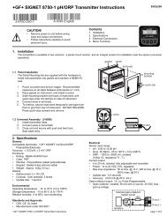
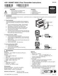
+GF+ SIGNET <strong>8550</strong>-2 Flow Transmitter Instructions<br />
ENGLISH<br />
3-<strong>8550</strong>.090-2 (A-9/99) English<br />
CAUTION!<br />
• Remove power to unit before wiring<br />
input and output connections.<br />
• Follow instructions carefully to avoid<br />
personal injury.<br />
Contents<br />
1. Installation<br />
2. Specifications<br />
3. Electrical Connections<br />
4. Menu Functions<br />
Flow<br />
Flow 6.25 GPM<br />
Total 1234567.8><br />
Relay 1 Relay 2<br />
ENTER<br />
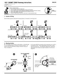
1. Installation<br />
The transmitter is available in three versions: a panel mount version, an integral (pipe mount) version, and a universal assembly for<br />
installation near the sensor.<br />
panel<br />
1.1 Panel Installation<br />
The Panel Mounting kits are supplied with the hardware to<br />
install instrumentation into panels and maintain a NEMA 4X<br />
seal.<br />
1. Punch out panel and de-burr edges. Recommended<br />
clearance on all sides between instruments is 1 inch.<br />
2. Place gasket on instrument, and install in panel.<br />
3. Slide mounting bracket over back of instrument until<br />
quick-clips snap into latches on side of instrument.<br />
4. Connect wires to terminals.<br />
5. To remove, secure instrument temporarily with tape from<br />
front or grip from rear of instrument. DO NOT RELEASE.<br />
Press quick-clips outward and remove.<br />
gasket<br />
latch<br />
transmitter<br />
terminals<br />
mounting<br />
bracket<br />
quick-clip<br />
1.2 Integral Assembly (3-8051)<br />
1. Punch out conduit ports if necessary.<br />
2. Connect sensor to integral adapter. Push and twist-lock<br />
integral adapter to conduit base and secure with locking<br />
ring and screw.<br />
3. Mount unit in pipe. Route cable through cable gland and<br />
connect to transmitter.<br />
4. Close unit and secure. Seal cable entry.<br />
cable<br />
gland<br />
seal<br />
1.3 Universal Assembly (3-8050)<br />
1. Install transmitter base<br />
2. Connect wires to transmitter.<br />
3. Close unit and secure with push and twist lock.<br />
Seal cable entry.<br />
wires<br />
seal<br />
2 . Specifications<br />
General<br />
Compatibility: +GF+ SIGNET Flow Sensors (w/freq out)<br />
Accuracy: ±0.5 Hz<br />
Enclosure:<br />
• Rating: NEMA 4X/IP65 front<br />
• Case: PBT<br />
• Window: Polyurethane coated polycarbonate<br />
• Keypad: Sealed 4-key silicone rubber<br />
• Weight: Approx. 325g (12 oz.)<br />
Display:<br />
• Alphanumeric 2 x 16 LCD<br />
• Update rate: 1 second<br />
• Contrast: User selected, 5 levels<br />
Environmental<br />
Operating temperature: -10 to 70°C (14 to 158°F)<br />
Storage temperature: -15 to 80°C (5 to 176°F)<br />
Relative humidity: 0 to 95%, non-condensing<br />
Standards and Approvals<br />
• CSA, CE, UL listed<br />
• Manufactured under ISO 9001<br />
Electrical<br />
Sensor Input:<br />
• Range: 0.5 to 1500 Hz<br />
• Sensor power: 2-wire: 1.5 mA @ 5 VDC ± 1%<br />
3 or 4 wire: 20 mA @ 5 VDC ± 1%<br />
• Optically isolated from current loop<br />
• Short circuit protected<br />
Current output:<br />
• 4 to 20 mA, isolated, fully adjustable and reversible<br />
• Power: 12 to 24 VDC ±10%, regulated<br />
• Max loop impedance: 50 Ω max. @ 12 V, 325 Ω max. @ 18 V,<br />
600 Ω max. @ 24V<br />
• Update rate: 100 ms<br />
• Accuracy: ±0.03 mA<br />
Relay outputs (2 sets):<br />
• Mechanical SPDT contacts: Hi, Lo, Pulse Programmable<br />
• Maximum voltage rating: 5 A @ 30 VDC, 5 A @ 250 VAC<br />
resistive load<br />
• Hysteresis: User adjustable<br />
+GF+ SIGNET <strong>8550</strong>-2 Flow Transmitter Instructions Provided by <strong>KTH</strong> <strong>Sales</strong>,<strong>Inc</strong>. www.<strong>KTH</strong> <strong>Sales</strong>.com Page 1 of 5
Dimensions<br />
Panel Mount<br />
96mm (3.8 in.)<br />
Field Mount<br />
96 mm (3.8 in.)<br />
Panel Cutout<br />
96 mm<br />
(3.8 in.)<br />
Optional<br />
Rear Cover<br />
92 x 92 mm<br />
(+ 0.8, - 0 mm)<br />
3.6 x 3.6 in.<br />
(+0.031, -0 in.)<br />
96 mm<br />
(3.8 in.)<br />
82 mm<br />
(3.23 in.)<br />
41 mm<br />
(1.6 in.)<br />
56 mm<br />
(2.2 in.)<br />
97 mm<br />
(3.8 in.)<br />
102 mm<br />
(4.0 in.)<br />
3. Electrical Connections<br />
Caution: Failure to fully open terminal jaws before removing wire may permanently damage instrument.<br />
Wiring Procedure<br />
1. Remove 0.5 - 0.625 in. (13-16 mm) of insulation from wire end.<br />
2. Press the orange terminal lever downward with a small screwdriver to open terminal jaws.<br />
3. Insert exposed (non-insulated) wire end in terminal hole until it bottoms out.<br />
4. Release orange terminal lever to secure wire in place. Gently pull on each wire to ensure a good connection.<br />
2<br />
1<br />
Wiring Removal Procedure<br />
1. Press the orange terminal lever downward with a small screwdriver to open terminal jaws.<br />
2. When fully open, remove wire from terminal.<br />
Terminals<br />
1. AUX Power +<br />
2. AUX Power -<br />
Description<br />
12-24 VDC<br />
System Power/Loop<br />
3. System Power/Loop +<br />
4. System Power/Loop -<br />
12-24 VDC ±5%, system power and current loop connections.<br />
Max. loop impedence: 50 Ω max @12 V, 600 Ω max. @ 24 V.<br />
Relays<br />
5. Relay 1 NC contact<br />
6. Relay 1 COM contact<br />
7. Relay 1 NO contact<br />
8. Relay 2 NC contact<br />
9. Relay 2 COM contact<br />
10. Relay 2 NO contact<br />
Sensor Input<br />
11. Black (Sensr V+)<br />
12. Red (Sensr IN)<br />
13. Silver (Sensr GND)<br />
Relay 1 / 2 contact sets programmable as:<br />
• High/Low alarm with adjustable hysteresis<br />
• Proportional pulse output<br />
• Disable (Off) selection<br />
4<br />
3<br />
2<br />
1<br />
System Pwr<br />
Loop -<br />
System Pwr<br />
Loop +<br />
AUX<br />
Power -<br />
AUX<br />
Power +<br />
10<br />
9<br />
8<br />
7<br />
6<br />
5<br />
Relay 2<br />
(NO)<br />
Relay 2<br />
(COM)<br />
Relay 2<br />
(NC)<br />
Relay 1<br />
(NO)<br />
Relay 1<br />
(COM)<br />
Relay 1<br />
(NC)<br />
13<br />
12<br />
11<br />
Sensr Gnd<br />
(SHIELD)<br />
Sensr IN<br />
(RED)<br />
Sensr V+<br />
(BLACK)<br />
Wiring Tips:<br />
• Do not route sensor cable in conduit containing AC power wiring - electrical noise may interfere with sensor signal.<br />
• Routing sensor cabling in grounded metal conduit may prevent moisture damage, electrical noise, and mechanical damage.<br />
• Seal cable entry points to prevent moisture damage.<br />
• When placing two wire ends into a single terminal, solder or crimp ends together.<br />
page 2 of 6<br />
+GF+ SIGNET <strong>8550</strong>-2 Flow Transmitter Instructions
3.1 System Power/Loop Connections<br />
Stand-alone application, no current loop used<br />
Connection to a PLC with built-in power supply<br />
Transmitter<br />
Terminals<br />
Sys. Pwr.<br />
Loop -<br />
Sys. Pwr.<br />
Loop +<br />
AUX<br />
Power -<br />
AUX<br />
Power +<br />
4<br />
3<br />
2<br />
1<br />
Power Supply<br />
DC 12 - 24 V<br />
-<br />
+<br />
Power<br />
Supply<br />
Power<br />
Supply<br />
Transmitter<br />
Sys. Pwr.<br />
Loop -<br />
Sys. Pwr.<br />
Loop +<br />
AUX<br />
Power -<br />
AUX<br />
Power +<br />
Terminals<br />
4<br />
3<br />
2<br />
1<br />
Internal PLC<br />
Connection<br />
PLC<br />
-<br />
+<br />
-<br />
+<br />
Terminals<br />
Power Supply<br />
Ground<br />
Power<br />
Supply<br />
Loop Input<br />
4-20 mA<br />
Loop Input<br />
4-20 mA<br />
Connection to a PLC/Recorder, separate supply<br />
Transmitter<br />
Sys. Pwr.<br />
Loop -<br />
Sys. Pwr.<br />
Loop +<br />
AUX<br />
Power -<br />
AUX<br />
Power +<br />
Terminals<br />
4<br />
3<br />
2<br />
1<br />
-<br />
+<br />
PLC or Recorder<br />
-<br />
+<br />
DC 12 - 24 V<br />
Power<br />
Supply<br />
Power<br />
Supply<br />
Loop Input<br />
4-20 mA in<br />
Loop Input<br />
4-20 mA in<br />
Example: Two transmitters connected to PLC/Recorder<br />
with separate power supply<br />
Transmitter 1<br />
DC 12 - 24 V<br />
-<br />
+<br />
Sys. Pwr.<br />
Loop -<br />
Sys. Pwr.<br />
Loop +<br />
AUX<br />
Power -<br />
AUX<br />
Power +<br />
4<br />
3<br />
2<br />
1<br />
Transmitter 2<br />
Sys. Pwr.<br />
Loop -<br />
Sys. Pwr.<br />
Loop +<br />
AUX<br />
Power -<br />
AUX<br />
Power +<br />
4<br />
3<br />
2<br />
1<br />
Power<br />
Supply<br />
Power<br />
Supply<br />
PLC or Recorder<br />
Channel 1<br />
4-20 mA in<br />
-<br />
+<br />
-<br />
+<br />
Channel 1<br />
4-20 mA in<br />
Channel 2<br />
4-20 mA in<br />
Channel 2<br />
4-20 mA in<br />
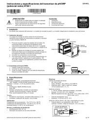
3.2 Sensor Input Connections<br />
Wiring Tip:<br />
Do not route sensor cable in any conduit<br />
containing AC power wiring - electrical<br />
noise may interfere with the signal.<br />
Terminals<br />
13<br />
12<br />
11<br />
Sensr Gnd<br />
(SHIELD)<br />
Sensr IN<br />
(RED)<br />
Sensr V+<br />
(BLACK)<br />
515<br />
525<br />
2100<br />
2517<br />
2536<br />
3-8510-XX<br />
3-8512-XX<br />
2540<br />
Vortex<br />
2000<br />
2507<br />
2530<br />
2535<br />
3.3 Open Collector Functions<br />
• Low: Output triggers when process variable is less than<br />
setpoint.<br />
• High: Output triggers when process variable is higher than<br />
setpoint.<br />
Example: In Low Alarm Mode Operation, the output becomes<br />
active when the process drops below the setpoint, and<br />
becomes inactive when the process rises above the setpoint<br />
plus hysteresis. The opposite is true for High Alarm Mode.<br />
• Off: Disables output pulse.<br />
• Pulse: Outputs a pulse whenever a specified amount of<br />
volume has been totalized.<br />
• Frequency: Outputs a pulse whenever the divided number of<br />
pulses are input.<br />
Output active<br />
Output inactive<br />
Process<br />
Hysteresis<br />
Setpoint<br />
Time<br />
+GF+ SIGNET <strong>8550</strong>-2 Flow Transmitter Instructions<br />
page 3 of 6
4. Menu Functions<br />
VIEW Menu: is displayed during standard operation.<br />
• Press UP or DOWN buttons to view process parameters.<br />
• Press UP and DOWN buttons at the same time, to exit any<br />
other display and return to VIEW menu.<br />
• Display will return to VIEW menu in 10 minutes unless a key<br />
is pressed.<br />
CALIBRATE Menu: contains display setup and output<br />
parameters. A security code feature prevents unauthorized<br />
tampering. To access CALIBRATE menu:<br />
• Press ENTER button for 2 seconds to display:<br />
• Press UP, UP, UP, DOWN buttons in sequence<br />
to display:<br />
CALIBRATE: ----<br />
Enter Key Code<br />
CALIBRATE: XXXX<br />
Enter Key Code<br />
OPTIONS Menu: contains setup and display features for minor<br />
display or output adjustments. To access OPTIONS menu:<br />
• Press ENTER button for 5 seconds to display:<br />
• Press UP, UP, UP, DOWN buttons in sequence<br />
to display:<br />
OPTIONS: ----<br />
Enter Key Code<br />
OPTIONS: XXXX<br />
Enter Key Code<br />
Menu Tips<br />
• Right button scrolls to right, from top to bottom row, and allows<br />
editing when ">" symbol is shown.<br />
• In CALIBRATE or OPTIONS menus, the transmitter will<br />
continue to measure and control outputs. When > is pressed,<br />
the input value is held at the last measured process value.<br />
• When sensor is not connected, unit will display CHECK<br />
SENSOR and any output controlled by sensor will be at 3.6 mA<br />
or OFF.<br />
Example<br />
To change date, first enter CALIBRATE menu (Press ENTER button for 2 seconds; Press UP, UP, UP, DOWN buttons in sequence)<br />
Once in CALIBRATE menu, press UP button 1 time.<br />
1. Display shows right<br />
arrow<br />
2. Press RIGHT button<br />
to display "01" blinking<br />
3. Press buttons to scroll<br />
through numbers.<br />
4. Press ENTER button<br />
to save<br />
5. Display now reads<br />
new date<br />
LAST CAL:<br />
01-01-99 ><br />
LAST CAL:<br />
01-01-99<br />
LAST CAL:<br />
08-01-99<br />
SAVING<br />
LAST CAL:<br />
08-01-99<br />
+GF+ SIGNET<br />
+GF+ SIGNET +GF+ SIGNET<br />
+GF+ SIGNET +GF+ SIGNET<br />
ENTER<br />
ENTER<br />
ENTER<br />
ENTER<br />
ENTER<br />
Menu Functions<br />
View Menu Range Calibrate Menu Range Preset Options Menu Range Preset<br />
Flow units 00000 - 99999 Flow Units: a-z,A-Z,/,3, GPM Contrast: 1-5 3<br />
Total: > GPM > s,h,m,d Level ><br />
Total Reset Lock: OFF s=seconds Flow Decimal: *.**** to ****.*<br />
Reset Total? 00000000 h=hours ***.** > *****.<br />
Total Reset Lock: ON m=minutes<br />
Reset Total? d=days Total Decimal: ******.** to ********.<br />
Key Code ---- Flow K-Factor: 0.0000 to 60.00 ********. > ********.<br />
Perm: 00000000 - > 99999 Averaging: Off Off<br />
Total Units 99999999 Total Units: a-z,A-Z,/,0-9 Gallons Off > Low (4secs)<br />
Gallons > eight digit High(8secs)<br />
Loop Output: 4-20 mA field Total Reset: On Off<br />
mA Total K-Factor: 0.0000 to 60.00 Lock Off > Off<br />
60.00 > 99999 Loop Adjust: 3.8 to 4.00<br />
Last Cal: 00-00-00 to Loop Range: GPM 0.0000 to 0 to 100 4.00 mA > 5.0 mA mA<br />
Date 39-39-99 000.00->100.00> 99999 Loop Adjust: 19.0 to 20<br />
20.00 mA > 21.0 mA mA<br />
Relay1 Mode: Off Low (Relay1) Test Loop: 4-20 mA N/A<br />
Low > Low High (Relay2) ><br />
High Test Relay1: On or N/A<br />
Pulse > Off<br />
Test Relay2: On or N/A<br />
Low or High selected > Off<br />
Settings repeat for Relay 2 Relay1 Setpnt: 0.0000 to 99999 10 (Relay1)<br />
10.0 GPM > 90 (Relay2)<br />
Relay1 Hys: 0.0000 to 99999 5 gpm<br />
5.0 GPM ><br />
Pulse Selected<br />
Relay1 Volume: 0.0000 to 99999 100<br />
100.00 Gallons ><br />
Relay1 Plswdth: 0.1 to 999.9 0.1 seconds<br />
0.1 Seconds > seconds<br />
Last Cal: 00-00-00 to 01-01-99<br />
01-01-99 > 39-39-99<br />
page 4 of 6<br />
+GF+ SIGNET <strong>8550</strong>-2 Flow Transmitter Instructions
Troubleshooting<br />
Display<br />
——<br />
Check settings<br />
for Output<br />
SETUP READ ERROR<br />
Press Any Key<br />
Problem<br />
Display timebase too large<br />
Pulse width value too large for frequency<br />
input or pulse volume too small<br />
Memory fault occurred.<br />
Solution<br />
Change flow timebase<br />
(S=seconds,M=minutes,H=hours,D=days) in CALIBRATE<br />
menu to a smaller value (e.g. GPD to GPM<br />
Reduce output Plswidth setting or increase Output Volume<br />
setting.<br />
Press any key to reload presets, then reprogram setpoints.<br />
Provided by <strong>KTH</strong> <strong>Sales</strong>, <strong>Inc</strong>.<br />
www.<strong>KTH</strong><strong>Sales</strong>.com