Hoval Cosmo heating boilers, outputs from 100 to - MacFarlane ...
Hoval Cosmo heating boilers, outputs from 100 to - MacFarlane ...
Hoval Cosmo heating boilers, outputs from 100 to - MacFarlane ...

You also want an ePaper? Increase the reach of your titles
YUMPU automatically turns print PDFs into web optimized ePapers that Google loves.
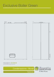
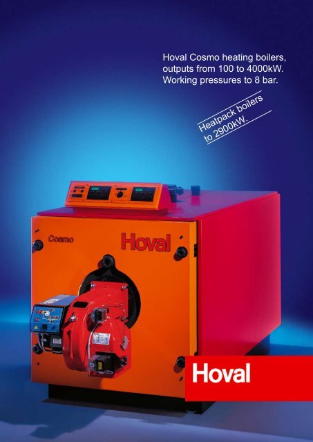
<strong>Hoval</strong> <strong>Cosmo</strong> <strong>heating</strong> <strong>boilers</strong>,<br />
<strong>outputs</strong> <strong>from</strong> <strong>100</strong> <strong>to</strong> 4000kW.<br />
Working pressures <strong>to</strong> 8 bar.<br />
Heatpack <strong>boilers</strong><br />
<strong>to</strong> 2900kW.
Whether your application is for single, multiple or space saving<br />
heatpack <strong>boilers</strong>, <strong>Hoval</strong> always have the solution.<br />
If only everything could be as versatile as the high efficiency <strong>Hoval</strong><br />
<strong>Cosmo</strong>.
General<br />
The <strong>Hoval</strong> <strong>Cosmo</strong> has been developed <strong>from</strong> our well proven steel boiler<br />
design <strong>to</strong> give greater specifier options in meeting the latest efficiency and<br />
emissions legislation. The <strong>Cosmo</strong> boiler is designed and manufactured under<br />
EN ISO 9001 and is fully CE-marked.<br />
Key Benefits<br />
● No minimum water flow rate is required due <strong>to</strong> the generous boiler water<br />
content.<br />
● Unique third pass tube design for improved heat transfer rate.<br />
● Boiler quality steel chamber and shell construction with heavy grade tubes.<br />
● Standing losses typically 0.3%.<br />
● Hinged boiler door and bolt-on smoke box provides easy access for<br />
cleaning and maintenance.<br />
● Suitable for firing with a range of matched burners for use with gas<br />
(including bio-gas), oil (including bio-diesel) or dual fuel.<br />
● Rear connections allow a second boiler <strong>to</strong> be stacked on <strong>to</strong>p <strong>to</strong> form a<br />
<strong>Cosmo</strong>-Heatpack.<br />
<strong>Cosmo</strong><br />
● Extremely reliable offering both high efficiency performance <strong>to</strong>gether with<br />
low NOx emissions.<br />
● Operating temperatures up <strong>to</strong> <strong>100</strong>°C. (Higher temperature version with PED<br />
certification available on request)<br />
● Working pressure 6 bar as standard.<br />
● 8 bar model available on request.<br />
● Efficiency <strong>to</strong> 92% net.<br />
<strong>Cosmo</strong>-plus<br />
● Matched <strong>to</strong> a wide range of burners including fully modulating and<br />
Ultra-low NOx.<br />
● Burner selections have additional fan power <strong>to</strong> overcome the resistance of<br />
the ThermoCondensor unit when the <strong>Cosmo</strong>-Condens package is specified.<br />
● Special retarders fitted for improved efficiency <strong>to</strong> 94% net.<br />
<strong>Cosmo</strong>-Condens<br />
● Combined with a <strong>Hoval</strong> TC-AF thermocondensor unit (left), the<br />
<strong>Cosmo</strong>-Condens can achieve efficiencies of up <strong>to</strong> 107% net on gas.<br />
(See separate page for details).<br />
<strong>Cosmo</strong>-Heatpack<br />
● Where there are space limitations in the plantroom the <strong>Cosmo</strong> and the<br />
<strong>Cosmo</strong>-plus <strong>boilers</strong> can be stacked <strong>to</strong> form the <strong>Cosmo</strong>-Heatpack or the<br />
<strong>Cosmo</strong>-plus Heatpack. The Heatpack solution gives double the output<br />
capability within the same footprint area as a standard boiler.<br />
Controls<br />
All <strong>Cosmo</strong> <strong>boilers</strong> are supplied with an integral control panel, which is <strong>to</strong>pmounted<br />
on <strong>boilers</strong> up <strong>to</strong> the <strong>Cosmo</strong> 2500 model and side-mounted on larger<br />
sizes <strong>to</strong>gether with the <strong>Cosmo</strong> Heatpack models.<br />
The standard control panel incorporates the following:<br />
● Flow thermometer.<br />
● Temperature control thermostat(s).<br />
● High temperature limit thermostat with manual reset.<br />
● On/off switch.<br />
● Excess temperature, burner run, burner lockout and high fire indica<strong>to</strong>rs.<br />
Optional items include:<br />
● Volt free contacts (for BMS interface)<br />
● Hours run meter<br />
● Burner modulating controller<br />
● Flue gas thermometer and altitude gauge.<br />
TopTronic control<br />
Alternatively <strong>Hoval</strong> TopTronic controller(s) can be specified, providing a<br />
simple user friendly operating platform that controls individual <strong>heating</strong> and hot<br />
water systems and optimises energy consumption.
<strong>Cosmo</strong> and <strong>Cosmo</strong>-plus <strong>boilers</strong> can be fired using gas, oil, or dual<br />
fuel pressure jet burners. The gas fired <strong>Cosmo</strong>-Condens combines<br />
the well proven <strong>Cosmo</strong> boiler and the TC-AF ThermoCondensor <strong>to</strong><br />
form a fully engineered and highly efficient condensing solution.<br />
TC-AF thermocondensor<br />
Where required TopTronic<br />
controllers can be fitted<br />
Stainless steel<br />
construction<br />
Doors can be hinged on either<br />
side.<br />
Combustion chamber sight glass<br />
Large combustion chamber<br />
helps reduce NOx<br />
emissions<br />
aluFer®<br />
tubes for maximum<br />
heat transfer<br />
Generous water volume<br />
permits no minimum water<br />
flow rate<br />
Dimpled tubes reduce laminar<br />
flow and increase efficiency<br />
Fully insulated combustion<br />
chamber for minimal standing<br />
losses<br />
Important:<br />
The return water temperature in<strong>to</strong> the <strong>Cosmo</strong> boiler<br />
must (if required) be raised <strong>to</strong> at least 55 o C <strong>to</strong><br />
prevent condensation of the flue gas in the boiler.<br />
<strong>Cosmo</strong>-Condens<br />
Combined with a TC-AF thermocondensor<br />
<strong>to</strong> form a fully engineered and matched<br />
package, the highly efficient <strong>Cosmo</strong> is<br />
even better, achieving up <strong>to</strong> 107% net<br />
efficiency on gas.<br />
The ThermoCondensor aluFer® TC-AF is<br />
an independent exhaust gas condensation<br />
heat recovery unit. It is available in five<br />
sizes and matched <strong>to</strong> <strong>Hoval</strong> gas fired<br />
pressure jet <strong>boilers</strong>.<br />
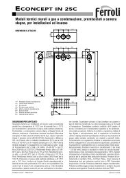
The TC-AF can be matched as a<br />
single unit with the <strong>Cosmo</strong> boiler up <strong>to</strong><br />
2000kW <strong>to</strong> achieve significant energy<br />
savings (see graph).<br />
<strong>Cosmo</strong>-Condens Energy Gains.<br />
<strong>Cosmo</strong>-Condens key benefits<br />
● Significant energy savings achieved at<br />
low return water temperature due <strong>to</strong><br />
higher efficiency<br />
● The heat exchanger utilises a bank of<br />
single pass patented aluFer® tubes<br />
constructed of an inner aluminium finned<br />
surface within an outer stainless steel<br />
tube.This provides maximum heat<br />
transfer and water-side corrosion<br />
resistance.<br />
● Greatest efficiency gains occur with<br />
return temperature of 40°C or lower.<br />
● Lower hydraulic resistance allows full<br />
system water flow through the unit.<br />
● Multi-position flue gas inlet connection<br />
aids site installation.<br />
● Compact design – minimum plant room<br />
requirements.<br />
● An optional condensate neutralisation<br />
reservoir can be supplied (if required by<br />
local by-laws), complete with a<br />
condensate discharge pump.<br />
● Burner matched <strong>to</strong> overcome boiler and<br />
ThermoCondensor flue gas combined<br />
resistance.<br />
Please refer <strong>to</strong> our separate TC-AF leaflet<br />
for further information.<br />
Chloride - Max chloride content of<br />
<strong>heating</strong> system water serving the<br />
ThermoCondensor is 50mg/litre.<br />
Approximate energy savings as a<br />
percentage of boiler capacity.<br />
18<br />
16<br />
14<br />
12<br />
10<br />
8<br />
6<br />
4<br />
220 o C<br />
200 o C<br />
180 o C<br />
160 o C<br />
Flue gas inlet temperature - ( o C)<br />
aluFer® tubes<br />
At the heart of the <strong>Hoval</strong>’s condensing<br />
technolgy, the revolutionary aluFer® tube<br />
maximizes heat transfer and efficiency.<br />
2<br />
25 30 35 40 45 50 55 60 65 70<br />
Temperature of hot water entering the ThermoCondensor ( o C).<br />
Temperature difference between hot water inlet and outlet at the Thermocondensor 5K.
<strong>Hoval</strong> <strong>Cosmo</strong><br />
Technical Data<br />
<strong>Cosmo</strong><br />
Type 175 240 290 350 410 465 585 700 850 950<br />
• Nominal output kW 174 241 291 350 410 465 584 701 850 950<br />
• Minimum output kW <strong>100</strong>.00 145.00 155.00 165.00 190.00 205.00 220.00 260.00 350.00 460.00<br />
• Boiler input at nominal output kW 191.25 262.51 317.75 382.51 448.09 508.42 639.35 765.24 929.96 1038.53<br />
• Boiler input at minimum output kW 109.65 158.12 169.58 180.33 207.42 224.04 236.56 278.07 375.94 491.45<br />
• Maximum boiler operating temperature (1) °C <strong>100</strong> <strong>100</strong> <strong>100</strong> <strong>100</strong> <strong>100</strong> <strong>100</strong> <strong>100</strong> <strong>100</strong> <strong>100</strong> <strong>100</strong><br />
• Minimum return temperature (oil/gas) °C 60/55 60/55 60/55 60/55 60/55 60/55 60/55 60/55 60/55 60/55<br />
• Minimum flue gas temperature °C 140 140 140 140 140 140 140 140 140 140<br />
• Maximum working pressure / test pressure (2) bar 6/9 6/9 6/9 6/9 6/9 6/9 6/9 6/9 6/9 6/9<br />
• Boiler efficiency net (3) at <strong>100</strong>%PN % 91.2 91.7 91.4 91.5 91.6 91.5 91.5 91.7 91.4 91.5<br />
at 30%PN % 93.9 93.5 93.6 93.8 93.8 93.9 93.0 93.5 93.1 93.6<br />
• Standing losses qB at 70°C Watt 600 800 800 900 1200 1200 1500 1600 1800 2000<br />
• Insulation thickness mm 70 70 70 70 70 70 70 70 70 70<br />
• Fuel Consumption at nominal output<br />
Nat Gas (4) m 3 /hr 19.83 27.22 32.99 39.67 46.47 52.72 66.19 79.27 96.44 107.67<br />
35 seconds oil (5) litres/hr 19.30 26.49 32.10 38.60 45.22 51.31 64.41 77.14 93.85 104.77<br />
• Hydraulic resistance through the boiler (6) z-fac<strong>to</strong>r 0.102 0.106 0.106 0.051 0.051 0.051 0.033 0.009 0.008 0.005<br />
• Hydraulic resistance with 11 K T m bar 18.95 37.50 54.77 38.18 52.49 67.42 68.76 27.02 35.31 27.57<br />
• Hydraulic resistance with 20 K T m bar 5.75 11.35 16.56 11.55 15.89 20.40 20.80 8.17 10.68 8.34<br />
• Water Flow rate with 11 K T m 3 / h 13.63 18.81 22.73 27.36 32.08 36.36 45.65 54.79 66.44 74.26<br />
• Water Flow rate with 20 K T m 3 / h 7.50 10.35 12.50 15.05 17.65 20.00 25.11 30.14 36.54 40.84<br />
• Boiler water content litres 270 333 385 396 455 574 617 697 837 1134<br />
• Dry Weight (without burner) (7) kg 577 640 695 801 862 932 1184 1273 1433 1792<br />
<strong>Cosmo</strong><br />
Type 1050 1200 1450 1800 2000 2500 3000 3500 4000<br />
• Nominal output kW 1051 1200 1450 1800 2000 2500 3000 3500 4000<br />
• Minimum output kW 480 570 650 882 1020 1225 1530 1715 1920<br />
• Boiler input at nominal output kW 1148.63 1311.49 1611.11 1975.8 2185.8 2741.2 3281.5 3833.5 4376.4<br />
• Boiler input at minimum output kW 511.72 608.32 695.93 947.4 1094.4 1310.1 1632.9 1834.2 2057.9<br />
• Maximum boiler operating temperature (1) °C <strong>100</strong> <strong>100</strong> <strong>100</strong> <strong>100</strong> <strong>100</strong> <strong>100</strong> <strong>100</strong> <strong>100</strong> <strong>100</strong><br />
• Minimum return temperature (oil/gas) °C 60/55 60/55 60/55 60/55 60/55 60/55 60/55 60/55 60/55<br />
• Minimum flue gas temperature °C 140 140 140 140 140 140 140 140 140<br />
• Maximum working pressure / test pressure (2) bar 6/9 6/9 6/9 6/9 6/9 6/9 6/9 6/9 6/9<br />
• Boiler efficiency net (3) at <strong>100</strong>%PN % 91.6 91.5 91.1 91.1 91.5 91.2 91.4 91.3 91.2<br />
at 30%PN % 93.8 93.7 93.4 93.1 93.2 93.5 93.7 93.6 93.3<br />
• Standing losses qB at 70°C Watt 2000 2<strong>100</strong> 2300 2290 2370 2560 2950 3050 3150<br />
• Insulation thickness mm 70 70 70 70 70 70 70 70 70<br />
• Fuel Consumption at nominal output<br />
Nat Gas (4) m 3 /hr 118.87 136.00 165.05 204.89 226.66 284.26 340.37 397.53 454..82<br />
35 seconds oil (5) litres/hr 115.68 132.35 160.62 199.39 220.58 276.63 331.23 386.86 442.61<br />
• Hydraulic resistance through the boiler (6) z-fac<strong>to</strong>r 0.005 0.005 0.005 0.0034 0.0029 0.0012 0.0012 0.0011 0.0010<br />
• Hydraulic resistance with 11 K T m bar 33.68 43.99 56.52 67.30 70.87 45.82 65.98 82.33 97.75<br />
• Hydraulic resistance with 20 K T m bar 10.19 13.31 17.10 20.36 21.44 13.86 19.96 24.91 29.57<br />
• Water Flow rate with 11 K T m 3 / h 82.07 93.80 113.34 140.70 156.33 195.41 234.49 273.57 312.66<br />
• Water Flow rate with 20 K T m 3 / h 45.14 51.59 62.34 77.38 85.98 107.48 128.97 150.47 171.96<br />
• Boiler water content litres 1134 1138 1520 2710 2927 3417 4810 5515 5930<br />
• Dry Weight (without burner) (7) kg 1792 2004 2380 4800 5300 5900 6850 7200 7700<br />
(1) Based on a maximum limit thermostat setting of 110 o C. <strong>Cosmo</strong> <strong>boilers</strong> suitable<br />
for higher operating temperatures conforming <strong>to</strong> the PED are available on<br />
request (<strong>to</strong> model 1450 only).<br />
Alternatively refer <strong>to</strong> the THW-I HTE boiler leaflet for other high temperature<br />
boiler options.<br />
(2) Refers <strong>to</strong> all standard <strong>Cosmo</strong> <strong>boilers</strong>, a higher pressure version is<br />
available on request, (8 bar maximum operating pressure / 12 bar test).<br />
(3) Boiler efficiencies at <strong>100</strong>% load are based on a mean operating temperature<br />
of 70 o C, at 30% efficiencies are based on a mean temperature of 50 o C.<br />
(4) Based on gross CV 38.5 MJ/m 3 .<br />
(5) Based on gross CV 45.5 MJ/kg and specific gravity 0.835.<br />
(6) Hydraulic resistance (mbar) = (Flow rate (m 3 /h)) 2 x z<br />
(7) Dry weights based on the 6 bar boiler, <strong>to</strong> calculate the weight of an 8 bar<br />
version add 30%.
<strong>Hoval</strong> <strong>Cosmo</strong> Heating Boiler<br />
Dimensions and Technical Information<br />
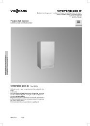
<strong>Cosmo</strong> <strong>heating</strong> boiler (models 175 <strong>to</strong> 1450)<br />
a<br />
m<br />
m<br />
Control panels are<br />
mounted on <strong>to</strong>p as<br />
standard but can be<br />
mounted on either side<br />
if required.<br />
7<br />
6<br />
i<br />
8<br />
205<br />
7<br />
2<br />
1<br />
Burner C L<br />
5<br />
b<br />
l<br />
5<br />
d<br />
k<br />
j<br />
4<br />
3<br />
9<br />
e<br />
1 Flow #<br />
2 Return #<br />
3 Hydraulic drain<br />
4 Condensate drain<br />
5 Flue outlet<br />
6 Au<strong>to</strong>matic air vent<br />
7 Control panel<br />
8 Plugged vent connection<br />
9 Smokebox cleaning door<br />
#<br />
Flanges PN16 on 8 bar <strong>boilers</strong><br />
f<br />
g<br />
Note:<br />
h<br />
Smokebox cleaning door<br />
behind removeable cover<br />
The installer must fit a safety valve in the flow pipework before any isolation valve.<br />
The installer must ensure the au<strong>to</strong>matic air vent (6) is fitted.<br />
The installer must ensure the condensate drain connection (4) is piped <strong>to</strong> drain via a<br />
drain trap <strong>to</strong> prevent flue gases escaping. Do not fit an isolation valve in this pipework.<br />
A single phase 230V supply is required for the control panel operation.<br />
Single phase burners are electrically supplied via the control panel.<br />
Three phase burners require a separate three phase isolated supply (by the installer)<br />
direct <strong>to</strong> the burner, incorporating a flexible connection <strong>to</strong> allow for boiler/burner door<br />
opening. In this case control cables fitted with wieland plug/sockets will still run<br />
between the control panel and the burner.<br />
n<br />
c<br />
205<br />
<strong>Cosmo</strong> Boiler 175 240 290 350 410 465 585 700 850 950 1050 1200 1450<br />
Dimensions:<br />
a (mm) 1610 1860 2060 1860 2060 2260 2070 2270 2620 2470 2470 2820 3120<br />
b (mm) 1033 1033 1033 1141 1141 1141 1334 1334 1334 1491 1491 1491 1491<br />
c (mm) 970 970 970 1078 1078 1078 1226 1226 1226 1400 1400 1400 1400<br />
d (mm) 552 552 552 606 606 606 725 725 725 795 795 795 795<br />
e (mm) 210 210 210 210 210 210 210 210 210 210 210 210 210<br />
f (mm) 1014 1264 1464 1264 1464 1664 1464 1664 2014 1864 1864 2214 2514<br />
g (mm) 1610 1860 2060 1860 2060 2260 2070 2270 2620 2470 2470 2820 3120<br />
h (mm) 386 386 386 386 386 386 396 396 396 391 391 391 391<br />
i (mm) 110 110 110 110 110 110 110 110 110 80 80 80 80<br />
j (mm) 73 73 73 73 73 73 80 80 80 80 80 80 80<br />
k (mm) 552 552 552 606 606 606 725 725 725 795 795 795 795<br />
l (mm) 931 931 931 1030 1030 1030 1224 1224 1224 1351 1351 1351 1351<br />
m (mm) 379 379 379 424 424 424 499 499 499 556 556 556 556<br />
n (mm) 920 920 920 1028 1028 1028 1176 1176 1176 1350 1350 1350 1350<br />
Connections:<br />
1 Flow # (PN6 # ) DN65 DN65 DN65 DN80 DN80 DN80 DN125 DN125 DN125 DN150 DN150 DN150 DN150<br />
2 Return # (PN6 # ) DN65 DN65 DN65 DN80 DN80 DN80 DN125 DN125 DN125 DN150 DN150 DN150 DN150<br />
3 Drain (BSP) G1.1/2<br />
ײ G1.1/2 ײ G1.1/2 ײ G1.1/2 ײ G1.1/2 ײ G1.1/2 ײ G2 ײ G2 ײ G2 ײ G2 ײ G2 ײ G2 ײ G2 ײ 4 Condensate drain (BSP) R1/2<br />
ײ R1/2 ײ R1/2 ײ R1/2 ײ R1/2 ײ R1/2 ײ R1/2 ײ R1/2 ײ R1/2 ײ R1/2 ײ R1/2 ײ R1/2 ײ R1/2 ײ 5 Flue O/Dia (mm) 245 245 245 295 295 295 345 345 345 395 395 395 395<br />
6 A.A.V. (BSP) G1/2<br />
ײ G1/2 ײ G1/2 ײ G1/2 ײ G1/2 ײ G1/2 ײ G1/2 ײ G1/2 ײ G1/2 ײ G1/2 ײ G1/2 ײ G1/2 ײ G1/2 ײ
<strong>Hoval</strong> <strong>Cosmo</strong> Heating Boiler<br />
Dimensions and Technical Information<br />
<strong>Cosmo</strong> <strong>heating</strong> boiler (models 1800 <strong>to</strong> 4000)<br />
7<br />
h<br />
2 1<br />
3<br />
60<br />
j<br />
d<br />
i<br />
<strong>100</strong> Chequer plate <strong>to</strong>p covers.<br />
205<br />
Control panels are<br />
mounted on <strong>to</strong>p or side<br />
on models 1800 <strong>to</strong> 2500,<br />
and side mounted on<br />
larger models.<br />
7<br />
Burner C L<br />
5<br />
8<br />
5<br />
8<br />
c<br />
f<br />
320<br />
b<br />
8<br />
6<br />
4 80<br />
g<br />
4<br />
e<br />
a<br />
6<br />
8<br />
205<br />
1 Flow<br />
2 Return<br />
3 Safety valve connection<br />
4 Hydraulic drain<br />
5 Flue outlet<br />
6 Condensate drain<br />
7 Control panel<br />
8 Smokebox cleaning door<br />
Note:<br />
The installer must ensure the condensate drain connection (6) is piped <strong>to</strong> drain via a<br />
drain trap <strong>to</strong> prevent flue gases escaping. Do not fit an isolation valve in this pipework.<br />
A single phase 230V supply is required for the control panel operation.<br />
Three phase burners require a separate three phase isolated supply (by the installer)<br />
direct <strong>to</strong> the burner, incorporating a flexible connection <strong>to</strong> allow for boiler/burner door<br />
opening. A separate control cable is fitted with wieland plug/sockets <strong>to</strong> run between<br />
the control panel and the burner.<br />
<strong>Cosmo</strong> Boiler 1800 2000 2500 3000 3500 4000<br />
Dimensions:<br />
a (mm) 1800 1800 1800 2200 2200 2200<br />
b (mm) 2534 2664 3234 3000 3200 3450<br />
c (mm) 1950 1950 1950 2350 2350 2350<br />
d (mm) 1<strong>100</strong> 1200 1300 1300 1500 1750<br />
e (mm) 1750 1750 1750 2150 2150 2150<br />
f (mm) 1025 1025 1025 1225 1225 1225<br />
g (mm) 1025 1025 1025 1225 1225 1225<br />
h (mm) 800 800 800 900 900 900<br />
i (mm) 750 750 750 800 800 800<br />
j (mm) 3270 3400 4000 3750 3050 4200<br />
Connections:<br />
1 Flow (PN16) DN150 DN200 DN200 DN200 DN200 DN200<br />
2 Return (PN16) DN150 DN200 DN200 DN200 DN200 DN200<br />
3 Safety valve (PN16) DN<strong>100</strong> DN<strong>100</strong> DN<strong>100</strong> DN<strong>100</strong> DN<strong>100</strong> DN<strong>100</strong><br />
4 Drain (BSP) G2<br />
ײ G2 ײ G2 ײ G2 ײ G2 ײ G2 ײ 5 Flue O/Dia (mm) 450 450 450 650 650 650<br />
6 Condensate drain (BSP) R1<br />
ײ R1 ײ R1 ײ R1 ײ R1 ײ R1 ײ
<strong>Hoval</strong> <strong>Cosmo</strong> Heatpack<br />
Dimensions and Technical Information<br />
<strong>Cosmo</strong> Heatpack (models 2x175 <strong>to</strong> 2x1450)<br />
a<br />
6<br />
Plugged vent.<br />
k<br />
6<br />
k<br />
2 1<br />
Burner C L<br />
5<br />
5<br />
b<br />
7<br />
6<br />
Plugged vent.<br />
Control panels<br />
can be mounted<br />
either side.<br />
4<br />
3<br />
c<br />
7<br />
m<br />
n<br />
2 1<br />
Burner C L<br />
5<br />
j<br />
o<br />
5<br />
d<br />
p<br />
4<br />
3<br />
e<br />
1 Flow #<br />
2 Return #<br />
3 Hydraulic Drain<br />
4 Condensate Drain<br />
f<br />
g<br />
5 Flue Outlet<br />
6 Au<strong>to</strong>matic air vent<br />
7 Control panels (on left or right)<br />
#<br />
Flanges PN16 on 8 bar <strong>boilers</strong><br />
Note:<br />
h<br />
i<br />
Smokebox cleaning door<br />
behind removeable cover<br />
q<br />
205 l<br />
205<br />
The installer must fit a safety valve in the flow pipework before any isolation valve.<br />
The installer must ensure the au<strong>to</strong>matic air vents (6) are fitted.<br />
The installer must ensure the condensate drain connection (4) is piped <strong>to</strong> drain via a drain<br />
trap <strong>to</strong> prevent flue gases escaping. Do not fit an isolation valve in this pipework.<br />
<strong>Cosmo</strong> Boiler 2x175 2x240 2x290 2x350 2x410 2x465 2x585 2x700 2x850 2x950 2x1050 2x1200 2x1450<br />
Dimensions:<br />
a (mm) 1610 1860 2060 1860 2060 2260 2070 2270 2620 2470 2470 2820 3120<br />
b (mm) 2087 2087 2087 2303 2303 2303 2690 2690 2690 3000 3000 3000 3000<br />
c (mm) 1606 1606 1606 1768 1768 1768 2080 2080 2080 2303 2303 2303 2303<br />
d (mm) 552 552 552 606 606 606 725 725 725 795 795 795 795<br />
e (mm) 210 210 210 210 210 210 210 210 210 210 210 210 210<br />
f (mm) 1014 1264 1464 1264 1464 1664 1464 1664 2014 1864 1864 2214 2514<br />
g (mm) 1610 1860 2060 1860 2060 2260 2070 2270 2620 2470 2470 2820 3120<br />
h (mm) 386 386 386 386 386 386 396 396 396 391 391 391 391<br />
i (mm) 73 73 73 73 73 73 80 80 80 80 80 80 80<br />
j (mm) 1054 1054 1054 1162 1162 1162 1355 1355 1355 1508 1508 1508 1508<br />
k (mm) 379 379 379 424 424 424 499 499 499 556 556 556 556<br />
l (mm) 970 970 970 1078 1078 1078 1226 1226 1226 1400 1400 1400 1400<br />
m (mm) 1985 1985 1985 2192 2192 2192 2579 2579 2579 2859 2859 2859 2859<br />
n (mm) 1606 1606 1606 1768 1768 1768 2080 2080 2080 2303 2303 2303 2303<br />
o (mm) 931 931 931 1030 1030 1030 1224 1224 1224 1351 1351 1351 1351<br />
p (mm) 552 552 552 606 606 606 725 725 725 795 795 795 795<br />
q (mm) 920 920 920 1028 1028 1028 1176 1176 1176 1350 1350 1350 1350<br />
Connections:<br />
1 Flow # (PN6 # ) DN65 DN65 DN65 DN80 DN80 DN80 DN125 DN125 DN125 DN150 DN150 DN150 DN150<br />
2 Return # (PN6 # ) DN65 DN65 DN65 DN80 DN80 DN80 DN125 DN125 DN125 DN150 DN150 DN150 DN150<br />
3 Drain (BSP) G1.1/2<br />
ײ G1.1/2 ײ G1.1/2 ײ G1.1/2 ײ G1.1/2 ײ G1.1/2 ײ G2 ײ G2 ײ G2 ײ G2 ײ G2 ײ G2 ײ G2 ײ 4 Condensate drain (BSP) R1/2<br />
ײ R1/2 ײ R1/2 ײ R1/2 ײ R1/2 ײ R1/2 ײ R1/2 ײ R1/2 ײ R1/2 ײ R1/2 ײ R1/2 ײ R1/2 ײ R1/2 ײ 5 Flue (O/Dia) (mm) 245 245 245 295 295 295 345 345 345 395 395 395 395<br />
6 A.A.V. (BSP) G1/2<br />
ײ G1/2 ײ G1/2 ײ G1/2 ײ G1/2 ײ G1/2 ײ G1/2 ײ G1/2 ײ G1/2 ײ G1/2 ײ G1/2 ײ G1/2 ײ G1/2 ײ
<strong>Hoval</strong> <strong>Cosmo</strong> Heating Boiler<br />
Installation Information<br />
Delivery and assembly<br />
All <strong>Cosmo</strong> <strong>boilers</strong> are delivered with burner,<br />
insulation, casings and control panel<br />
packed separately for fitting by the installer.<br />
Any ancilliary items such as safety valves,<br />
altitude gauges, drain valves, gas<br />
boosters etc, will also be supplied<br />
separately for fitting by the installer.<br />
Heatpack <strong>boilers</strong> will be supplied as<br />
two separate <strong>boilers</strong> for the installer the<br />
mount on site.<br />
Before mounting the burner, the front<br />
casing must be fitted. Likewise before<br />
connecting the flue, the rear casing<br />
must be fitted.<br />
<strong>Cosmo</strong> Boiler Model 175 240 290 350 410 465 585 700 850 950 1050 1200 1450 1800 2000 2500 3000 3500 4000<br />
Boiler<br />
Dimensions:<br />
L (mm) 1643 1893 2093 1893 2093 2293 2103 2303 2653 2501 2501 2851 3151 3240 3370 3970 3720 3920 4170<br />
W (mm) 920 920 920 1028 1028 1028 1176 1176 1176 1350 1350 1350 1350 1750 1750 1750 2150 2150 2150<br />
H or H1 #<br />
(mm) 1012 1012 1012 1120 1120 1120 1313 1313 1313 1470 1470 1470 1470 2010 2010 2010 2410 2410 2410<br />
Weight: (kg) 512 565 615 711 762 827 1078 1152 1302 1635 1635 1837 2218 4610 5090 5670 6400 6950 7390<br />
Casings Box Dimensions:<br />
Number of Boxes: 1 1 1 1 1 1 1 1 1 1 1 1 1 1 1 2 2 2 2<br />
L (mm) 2120 1880 1880 2120 2120 2120 2120 2110 2120 1920 1920 1920 1920 2120 2120 2120 2120 2120 2120<br />
W (mm) 330 230 270 300 300 300 300 300 350 350 350 330 330 350 350 350 350 350 350<br />
H (mm) 1330 <strong>100</strong>5 <strong>100</strong>5 1330 1330 1330 1330 1330 1330 1520 1520 1520 1520 1330 1330 1330 1330 1330 1330<br />
Weight per box: (kg) 145 90 90 <strong>100</strong> 110 115 120 135 145 175 175 175 200 240 260 140 150 150 180<br />
# Top connections as standard on <strong>Cosmo</strong> 1800-4000 <strong>boilers</strong><br />
Shipment dimensions and weights<br />
H1 #<br />
H<br />
W<br />
L<br />
Lifting shackle on <strong>boilers</strong> up <strong>to</strong> and<br />
including the <strong>Cosmo</strong> 465, lifting lugs<br />
either side of shell on larger <strong>boilers</strong>.<br />
K<br />
Minimum Access<br />
L<br />
W<br />
T<br />
K = (W÷T) x L<br />
T = (W÷K) x L<br />
T = Door opening<br />
K = Corridor width<br />
W = Boiler width<br />
L = Boiler length<br />
Plantroom Layout.<br />
Wherever possible, space should be left<br />
around the boiler <strong>to</strong> enable all parts <strong>to</strong> be<br />
examined and the cubicle casings <strong>to</strong> be<br />
fitted or removed easily.<br />
Front clearance: Space for the burner<br />
and the servicing of the equipment, must<br />
be accommodated. Ideally, front clearance<br />
should equate <strong>to</strong> the length of the boiler.<br />
This will permit the cleaning and removal<br />
of boiler tubes. The installer is advised<br />
<strong>to</strong> avoid creating obstructions which may<br />
hinder opening the boiler door, or the fitting<br />
of an acoustic shroud. These obstructions<br />
include; other plant, extended boiler plinths,<br />
extensive gas pipework, and rigid oil lines /<br />
burner power supplies.<br />
<strong>Hoval</strong> recommend the boiler plinth does not<br />
project beyond the front of the boiler as this<br />
will prevent a wheel over type shroud <strong>from</strong><br />
encapsulating the burner. Also, in some<br />
circumstances a plinth may be necessary<br />
<strong>to</strong> increase the firing height of the boiler<br />
<strong>to</strong> accomodate a particular burner. The<br />
installer must avoid, wherever practicable,<br />
the fitting of pipework within the swing of<br />
the boiler door. If this is not possible, a<br />
removeable s<strong>to</strong>ol piece with a shut off valve<br />
upstream must be fitted.<br />
Typical Plan View<br />
If 3ph burners<br />
are fitted, the<br />
installer should<br />
ensure that the<br />
power supply<br />
<strong>to</strong> the burner is<br />
flexible <strong>to</strong> allow<br />
the boiler door<br />
<strong>to</strong> fully open.<br />
Side Clearance: Generally a minimum<br />
clearance of <strong>100</strong>mm is required at the<br />
side of the boiler <strong>to</strong> fit and remove the side<br />
casings. Space <strong>to</strong> one side of the boiler is<br />
required <strong>to</strong> swing the boiler door with the<br />
burner fitted, (standard <strong>to</strong> the right, optional<br />
<strong>to</strong> left), whereby when the door is open 90 o ,<br />
the length of the burner+80mm will be at<br />
the side of the boiler. Normally the same<br />
access for the burner swing can also be<br />
used for getting <strong>to</strong> the back of the boiler.<br />
Where gas burners are fitted consideration<br />
should be given <strong>to</strong> the gas train (and<br />
booster if specified). Normally the gas<br />
mains are run either <strong>from</strong> high or low level.<br />
(Heatpack version shown)<br />
In both cases an elbow has <strong>to</strong> be fitted off<br />
the gas train <strong>to</strong> connect back <strong>to</strong> the header.<br />
Where gas trains fall within the width of<br />
the boiler this elbow has <strong>to</strong> be taken in<strong>to</strong><br />
account.<br />
Back clearance: is required for the flue<br />
and system connections and access <strong>to</strong> the<br />
cleaning door.<br />
Top clearance: is required above the boiler<br />
<strong>to</strong> fit safety valves, au<strong>to</strong>matic air vents and<br />
<strong>to</strong> access the <strong>to</strong>p boiler on Heatpack units.<br />
Shorter clearances are possible subject <strong>to</strong><br />
cleaning methods and plantroom layout.<br />
Please consult <strong>Hoval</strong> technical.
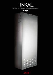
Other associated products<br />
<strong>Cosmo</strong>-Combination<br />
The <strong>Cosmo</strong>-combination boiler couples the tried and tested<br />
technology of the <strong>Cosmo</strong> boiler with that of the <strong>Hoval</strong> CT-plus<br />
and Modul-plus calorifier range. Mounted on <strong>to</strong>p, the calorifier<br />
combines with the boiler <strong>to</strong> provide a fully integrated package,<br />
including the primary circulating pump and DHW temperature<br />
control. ‘Mix & Match’ your DHW and <strong>heating</strong> requirements<br />
with a tailored combination package.<br />
<strong>Hoval</strong> Ltd<br />
Northgate<br />
Newark<br />
Notts<br />
NG24 1JN<br />
Tel: (01636) 672711<br />
Fax: (01636) 673532<br />
e-mail: <strong>boilers</strong>ales@hoval.co.uk<br />
Web Site: www.hoval.co.uk<br />
Uno-3<br />
The Uno-3 boiler couples high efficiency with low NOx<br />
emissions. These dual goals are achieved with the special<br />
3-pass design which incorporates the unique <strong>Hoval</strong><br />
thermolytic heat exchanger. Available as <strong>heating</strong> only units<br />
or with a calorifier as a combination unit, with ratings between<br />
50 -280 kW and DHW up <strong>to</strong> 1110 litres per hour. A modular<br />
heatpack version is also available up <strong>to</strong> 180 kW output.<br />
THW-I NTE and HTE<br />
The <strong>Hoval</strong> THW-I <strong>boilers</strong> are steel fabricated <strong>boilers</strong> based<br />
on the proven 3 pass wet back type construction with unique<br />
water cooled finned tube wall gas reversal chamber<br />
generating high efficiency. Design options allow for low,<br />
medium and high temperature / pressure applications <strong>from</strong><br />
1.5MW <strong>to</strong> 28MW boiler output. All boiler models are complete<br />
with Pressure Equipment Directive (PED) / CE certification.<br />
PressVal Micron<br />
The PressVal Micron range of pressurisation units are<br />
compact microprocessor controlled units. Covering all<br />
system ouputs <strong>from</strong> small commercial <strong>heating</strong> and chilled<br />
water systems, through <strong>to</strong> the very largest district <strong>heating</strong><br />
schemes. Both single and twin pump units are available in<br />
wall hung, free standing, skid mounted, or cabinet housed<br />
configuations. Volt free contacts provide a multitude of fault<br />
signals for BMS interface.<br />
May 2007<br />
By Appointment <strong>to</strong><br />
By Her Majesty the Queen<strong>to</strong><br />
Her Boiler Majesty Manufacturers the & Engineers Queen<br />
<strong>Hoval</strong> Limited, Newark<br />
Boiler Manufacturers & Engineers<br />
<strong>Hoval</strong> Ltd Newark.<br />
Conservation of energy - protection of the environment<br />
<strong>Hoval</strong> follows a policy of continued improvement and reserves the right <strong>to</strong> change specifications without notice.