Fibre C - Ravago
Fibre C - Ravago
Fibre C - Ravago

Create successful ePaper yourself
Turn your PDF publications into a flip-book with our unique Google optimized e-Paper software.
Planning Details<br />
Substructure<br />
Exclusively metal substructure.<br />
Fastening<br />
With undercut anchors and clips suspended in horizontal aluminium<br />
carrier profiles. Fasteners recommended in the system<br />
approval: Keil anchor (www.keil.eu) with the marking Hs=8.5 mm or<br />
equivalent.<br />
The undercut anchor must be tightened with a torque of 2.00 – 4.00<br />
Nm. Depending on the substructure used, there are suitable screws<br />
in different lengths. One must ensure that clips, anchors and<br />
screws belong to one system and match each other.<br />
Preparation<br />
In the fibreC plant, the panels are both tailored and prepared<br />
for fitting with undercut anchors. The bore holes for the<br />
undercut anchors can if required be pre-drilled in the factory.<br />
Any fastening agents required like system anchors,<br />
screws and metal profiles are not supplied by Rieder.<br />
Joint<br />
Joints must be at least 8 mm wide. If the horizontal joints are designed<br />
with 20 mm, panels can be unhooked or hooked on at a later<br />
date (please follow the manufacturer’s instructions). Depending on<br />
the substructure, a sponge rubber layer must be used between the<br />
clip and the panel. The length of the screw for the undercut anchor<br />
varies depending on the system.<br />
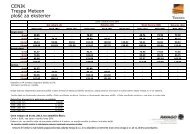
Fastening<br />
Absorbable loads of a panel fastened with four undercut anchors<br />
fibreC with undercut anchor<br />
panel thickness 13 mm<br />
panel width B [cm] span Y [cm] pressure/suction load<br />
40 4,4<br />
60 3,3<br />
60<br />
80 2,0<br />
100 1,3<br />
120 0,9<br />
40 3,1<br />
60 2,5<br />
80<br />
80 1,9<br />
100 1,2<br />
120 0,9<br />
40 1,8<br />
60 1,7<br />
100<br />
80 1,6<br />
100 1,1<br />
120 0,8<br />
40 1,2<br />
60 1,1<br />
120<br />
80 1,1<br />
100 1,0<br />
120 0,8<br />
Values in kN/m² (correspond to wk = cp*q)<br />
System sketch<br />
6-10 x 6-10<br />
B<br />
10 10<br />
Y<br />
How to read statics<br />
1. Select the panel width (B) .<br />
2. Choose the relevant span (Y) in<br />
column 2.<br />
3. In column 3 you can read the maximum<br />
absorbable loads.<br />
L = Y + 2*10<br />
Note<br />
All the visualisations in the brochure are schematic representations of the system and<br />
structural-physical requirements and project details are not included in the data. The services<br />
provided by the Company Firma Rieder Faserbeton-Elemente GmbH do not include<br />
static calculations. The sample calculation listed here does not dispense with an individual<br />
test by a structural designer. The Rieder Company does not accept any liability for statics.<br />
41