Fibre C - Ravago
Fibre C - Ravago
Fibre C - Ravago

You also want an ePaper? Increase the reach of your titles
YUMPU automatically turns print PDFs into web optimized ePapers that Google loves.
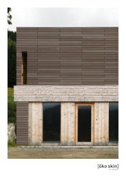
fibreC Design+<br />
Unlimited design possibilities<br />
In the design of cladding, there are hardly no limits on planners and<br />
architects with fibreC. The selection of ten different colours in each<br />
of three surface forms the basis. In line with current trends and<br />
developments, fibreC offers a range of additional procedures for<br />
the creation of individual building shells.<br />
fibreC offers a wide range of possibilities for printing the surface of<br />
the panel, irradiating designs, cutting out ornaments or lettering or<br />
incorporating a relief-like surface (e.g. a wood structure).<br />
What primarily characterises the material fibreC however, is the<br />
variations in the representation of shapes. With a specially developed<br />
method, it is possible, to make glassfibre reinforced concrete<br />
flow around corners, or produce formed elements. Two-dimensional<br />
standard formed elements can be produced in real time. We<br />
would be delighted to meet you in person to tell you about triaxial<br />
curved elements.<br />
··<br />
Perforation: Individual shapes or letters can be cut out of the<br />
panel using a water jet.<br />
··<br />
Sandblasting: Using specially made jet films, patterns, characters,<br />
or logos can be applied permanently to the panel surface<br />
··<br />
Digital or Screen printing: fibreC panels can be printed using<br />
either digital or screen printing. Printing images, photographs,<br />
designs and texts is suitable for both outside and inside.<br />
··<br />
Relief: Using a special technique, it is possible to produce<br />
relief-like rises on the fibreC panel<br />
··<br />
Formed elements: fibreC can be produced as U-shapes,<br />
arches, corners or other geometric shapes.<br />
··<br />
Three-dimensional special shapes: Basically everything is<br />
possible. We have special projects where we work on solutions<br />
to cater for your individual requirements like special shapes or<br />
2D and 3D formed elements.<br />
Material<br />
Perforation<br />
Base panel<br />
··<br />
Panel size: max. 3600/1200 mm (additional on request)<br />
··<br />
Panel thickness: 13 mm<br />
··<br />
Thickness tolerances: max. ± 1 mm<br />
··<br />
Surfaces: MA Matt, FL Ferro Light, FE Ferro<br />
··<br />
Back: untreated or FE Ferro<br />
Perforation<br />
··<br />
Perforation form: round, oval or square<br />
··<br />
Special shapes on request<br />
··<br />
Percentage of holes: max. 40 %<br />
··<br />
Hole diameter: min. 80 mm (others on request)<br />
··<br />
Distance to the panel edge: min. 80 mm<br />
··<br />
Distance between perforations: min. 60 mm<br />
Fastening<br />
··<br />
Visible and concealed fastening system possible<br />
··<br />
Fastening distance bore to bore max. 600 mm<br />
··<br />
Max. profile distances to the substructure 600 mm<br />
··<br />
Additional substructure to the fastening required based on the<br />
statics<br />
··<br />
Need to check the overall statics<br />
Handling<br />
··<br />
Panel fastening: manual or with suction pad<br />
··<br />
Handling the panel with particular care<br />
Sandblasting<br />
Base panel<br />
··<br />
Panel size: max. 3600/1200 mm (additional on request)<br />
··<br />
Panel thickness: 13 mm<br />
··<br />
Thickness tolerances: max. ± 1 mm<br />
··<br />
Surface: the base panel is always MA Matt<br />
··<br />
Colour: possible with all colours (effect depending on colour)<br />
··<br />
Back: untreated or FE Ferro<br />
Blasting<br />
··<br />
Logos and images can be negatively or positively blasted<br />
··<br />
Positive: lettering or image is opaque<br />
··<br />
Negative: lettering or image is sandblasted<br />
··<br />
Contour thickness > 5 mm<br />
··<br />
Distance to the panel edge: min. 80 mm<br />
Data<br />
Depending on the design, the data should be provided as an eps,<br />
dxf or dwg file. Where there are depictions or designs crossing<br />
over several panels, it is the customer’s responsibility to ensure<br />
that the logo runs from panel to panel taking the joint into consideration.<br />
A separate graphic file must be created for each panel.<br />
Handling<br />
··<br />
Panel fastening: manual or with suction pad<br />
··<br />
Handling the panel with particular care<br />
27