110 / 210 Fiber Optic Oxygen Monitor - Instech Laboratories, Inc.
110 / 210 Fiber Optic Oxygen Monitor - Instech Laboratories, Inc.
110 / 210 Fiber Optic Oxygen Monitor - Instech Laboratories, Inc.

Create successful ePaper yourself
Turn your PDF publications into a flip-book with our unique Google optimized e-Paper software.
11. Clean off all grease from the window valve. An<br />
acetone dampened tissue works well.<br />
12. Press the window valve back on to the chamber cup<br />
and rotate to distribute the grease across the face.<br />
13. Install the appropriate fill port plug into the top of the<br />
chamber. If you plan to use a plastic-tipped<br />
micropipette to add fluid to the chamber during<br />
your experiment, use the single-piece pipette<br />
plug. If you plan to use a microliter syringe, use<br />
the two-piece syringe plug.<br />
from the chamber block and that the setscrew does not<br />
protrude into the hole.<br />
2. Attach inlet and outlet tubes of your experiment to the<br />
flow cell. The system is designed for 1/16” ID tubing,<br />
such as Tygon.The flow cell is now ready for the<br />
probe.<br />
Pipette Fill<br />
Port Plug<br />
Hamilton Syringe<br />
Fill Port Plug<br />
The chamber is now ready for the electrode. When<br />
inserted, the electrode will hold the cup firmly in<br />
place.<br />
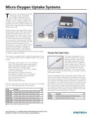
Setting up the Flow Cell<br />
Chamber<br />
Flow cell chamber assembly<br />
The various pieces of equipment designed for the batch cell<br />
mode (i.e., speed controller, motor, chamber cup, window<br />
valve, and red spacer) are not needed and should be set<br />
aside.<br />
Most in-line experiments involve measuring the difference<br />
in oxygen level at two points in a sy stem, and thus will<br />
require that you set up two flow cells.<br />
To set up the flow cell chamber:<br />
1. Insert the flow cell into the chamber block from the<br />
front. Be sure that batch cell parts have been removed<br />
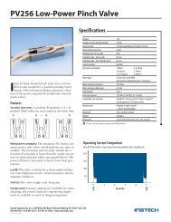
Titanium Micro<br />
Chamber<br />
Assembly<br />
Introduction<br />
This chamber is constructed of non-reactive titanium<br />
with volumes of 250 microliters to 1 ml. It is top<br />
loading for easy sample loading and clean out. A<br />
beveled, transparent, sample-sealing plug serves also<br />
as a valve by closing off the angled fill port when<br />
rotated. The angle on the plug allows air to be easily<br />
purged. An alternative acrylic plug with a central fill<br />
hole may also be provided. Miniature stirring system<br />
and a nickel/Teflon coated aluminum block are<br />
standard. Stirring is not required to achieve a stable<br />
reading with this type of probe but faster thermal<br />
equilibrium will be achieved and any particulates will<br />
be kept in suspension.<br />
7