EM-28 DC-MOTOR CONTROL UNIT 12-24V 3A - Electromen
EM-28 DC-MOTOR CONTROL UNIT 12-24V 3A - Electromen
EM-28 DC-MOTOR CONTROL UNIT 12-24V 3A - Electromen

You also want an ePaper? Increase the reach of your titles
YUMPU automatically turns print PDFs into web optimized ePapers that Google loves.
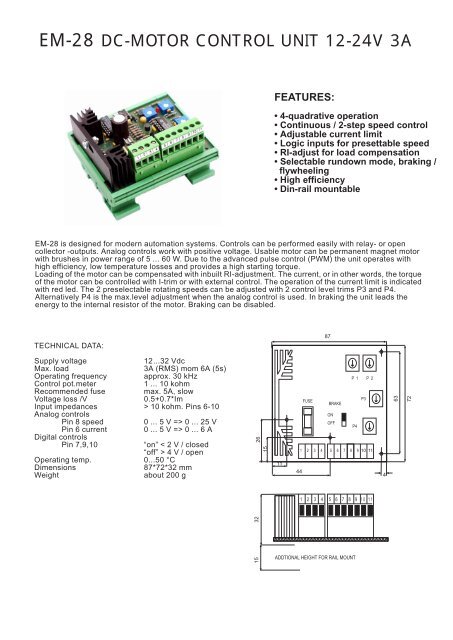
<strong>EM</strong>-<strong>28</strong> <strong>DC</strong>-<strong>MOTOR</strong> <strong>CONTROL</strong> <strong>UNIT</strong> <strong>12</strong>-<strong>24V</strong> <strong>3A</strong><br />
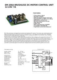
FEATURES:<br />
• 4-quadrative operation<br />
• Continuous / 2-step speed control<br />
• Adjustable current limit<br />
• Logic inputs for presettable speed<br />
• RI-adjust for load compensation<br />
• Selectable rundown mode, braking /<br />
flywheeling<br />
• High efficiency<br />
• Din-rail mountable<br />
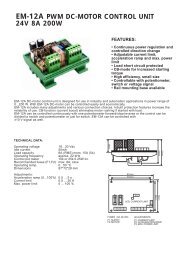
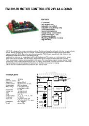
<strong>EM</strong>-<strong>28</strong> is designed for modern automation systems. Controls can be performed easily with relay- or open<br />
collector -outputs. Analog controls work with positive voltage. Usable motor can be permanent magnet motor<br />
with brushes in power range of 5 ... 60 W. Due to the advanced pulse control (PWM) the unit operates with<br />
high efficiency, low temperature losses and provides a high starting torque.<br />
Loading of the motor can be compensated with inbuilt RI-adjustment. The current, or in other words, the torque<br />
of the motor can be controlled with I-trim or with external control. The operation of the current limit is indicated<br />
with red led. The 2 preselectable rotating speeds can be adjusted with 2 control level trims P3 and P4.<br />
Alternatively P4 is the max.level adjustment when the analog control is used. In braking the unit leads the<br />
energy to the internal resistor of the motor. Braking can be disabled.<br />
TECHNICAL DATA:<br />
87<br />
Supply voltage<br />
<strong>12</strong>...32 Vdc<br />
Max. load<br />
<strong>3A</strong> (RMS) mom 6A (5s)<br />
Operating frequency approx. 30 kHz<br />
Control pot.meter<br />
1 ... 10 kohm<br />
Recommended fuse<br />
max. 5A, slow<br />
Voltage loss /V<br />
0.5+0.7*Im<br />
Input impedances > 10 kohm. Pins 6-10<br />
Analog controls<br />
Pin 8 speed<br />
0 ... 5 V => 0 ... 25 V<br />
Pin 6 current 0 ... 5 V => 0 ... 6 A<br />
Digital controls<br />
Pin 7,9,10<br />
“on” < 2 V / closed<br />
“off” > 4 V / open<br />
Operating temp. 0...50 °C<br />
Dimensions<br />
87*72*32 mm<br />
Weight<br />
about 200 g<br />
26<br />
15<br />
11<br />
44<br />
FUSE<br />
1 2 3 4<br />
P 1 P 2<br />
P3<br />
BRAKE<br />
ON<br />
OFF<br />
P4<br />
5 6 7 8 910 11<br />
4<br />
63<br />
72<br />
1 2 3 4<br />
5 6 7 8 9<br />
10 11<br />
15<br />
32<br />
ADDTIONAL HEIGHT FOR RAIL MOUNT
<strong>EM</strong>-<strong>28</strong> OPERATING AND CONNECTION INSTRUCTIONS<br />
INTRODUCTION<br />
Always disconnect supply before making connections. Operating voltage must be filtered <strong>DC</strong>-voltage with less<br />
than 25 % ripple at full load.<br />
ADJUSTMENTS<br />
Set all trims to the middle position. With analog control the maximum running speed is set with trim P4. When<br />
using the 2-step speed adjustment set the “fast” speed on (pin 9). Adjust the running speed to desired value with<br />
trim P4. Then change to the “slow” speed on (pin 10) and adjust the running speed to desired value with trim P3.<br />
The current limit adjustment is linear between 0 ... 6 A. The set value can be approximately determined from the<br />
position of the trim. When more precise adjustment is needed a current meter must be connected to motor circuit.<br />
The operation of the current limit is indicated with red led light. During the load compensation adjustment (P1)<br />
the load of the motor should be adjusted while observing the speed changes of the motor running speed. The<br />
compensation can be increased to point where the motor starts to twitch. Twitching is a sign of over<br />
compensation. The compensation adjustment has a slight effect on the running speed settings. _<br />
ADJUSTMENTS<br />
P1 LOAD COMPENSATION<br />
P2 CURRENT LIMIT (IF NO EXT. <strong>CONTROL</strong>)<br />
P3 PRESETTABLE SPEED “SLOW”<br />
P4 PRESETTABLE SPEED “FAST”<br />
OR MAX. LEVEL LIMIT<br />
1 2 3 4<br />
+ -<br />
CONNECTION OF <strong>MOTOR</strong><br />
AND SUPPLY<br />
min.<br />
min.<br />
min.<br />
0<br />
max.<br />
6A<br />
max.<br />
max.<br />
CONNECTIONS<br />
1 <strong>MOTOR</strong> - (MINUS)<br />
2 SUPPLY VOLTAGE <strong>12</strong> ... 32 V<br />
3 <strong>MOTOR</strong> + (PLUS)<br />
4 SUPPLY VOLTAGE (GND)<br />
5 <strong>CONTROL</strong> VOLTAGE 0V (GND)<br />
6 CURRENT LIMIT INPUT<br />
7 DIRECTION CHANGE<br />
8 SPEED <strong>CONTROL</strong> INPUT<br />
9 SELECTION OF PRESET SPEED (FAST)<br />
10 SELECTION OF PRESET SPEED (SLOW)<br />
11 +5.5 V REFERENCE OUTPUT MAX. 50 mA<br />
-<br />
M +<br />
SPEED ADJUSTMENT<br />
WITH POTENTIOMETER<br />
5 6 7 8 9 10 11<br />
SELECTION OF PRESET SPEED<br />
WITH SELECTION CONTACT<br />
5 6 7 8 9 10 11<br />
SPEED ADJUSTMENT<br />
WITH VOLTAGE SIGNAL<br />
5 6 7 8 9<br />
10 11<br />
SPEED<br />
“FAST”“<br />
SPEED<br />
“SLOW<br />
-<br />
Uin<br />
+<br />
POT 1...10kohm<br />
MAX. SET WITH TRIM P4<br />
“FAST" IS SET WITH TRIM P4<br />
“SLOW" IS SET WITH TRIM P3<br />
<strong>CONTROL</strong> 0 ... 5 V<br />
MAX. SET WITH TRIM P4<br />
DIRECTION SHIFT<br />
5 6 7 8 9<br />
10 11<br />
ADJUSTMENT OF TORQUE<br />
(CURRENT) WITH POTENTIOMETER<br />
5 6 7 8 9<br />
10 11<br />
ADJUSTMENT OF TORQUE<br />
WITH VOLTAGE SIGNAL<br />
5 6 7 8 9<br />
10 11<br />
-<br />
Uin<br />
+<br />
“FORWARD” OPEN OR VOLTAGE > 4 V<br />
“RESVERSE” CLOSE OR VOLTAGE < 2 V<br />
POTENTIOMETER 1...10 kohm<br />
TRIM P2 TO POSITION MIN<br />
<strong>CONTROL</strong> 0...5 V<br />
TRIM P2 TO POSITION MIN.<br />
ELECTROMEN Oy Vähäheikkiläntie 56B, 20810 Turku, FINLAND Tel. +358-2-4693050 Fax. +358-2-4693052