SERVICE MANUAL - Encompass Imaging
SERVICE MANUAL - Encompass Imaging SERVICE MANUAL - Encompass Imaging
TUNER / NTSC > ANT. Input ---------------------- 75 Ω Unbal., F type < TUNER / ATSC > < LCD PANEL > < VIDEO > < AUDIO > SPECIFICATIONS Description Condition Unit Nominal Limit 1. AFT Pull-In Range --- MHz ±2.3 ±2.1 2. Synchronizing Sens. TV.ch.4 CA.ch.31 CA.ch.87 Description Condition Unit Nominal Limit 1. Received Freq. Range (-28dBm) --- kHz --- ±100 2. ATSC Dynamic Range (min / max) 1. Native Pixel Resolution ch.4 ch.10 ch.41 dBµ dBµ dBµ dBm dBm dBm All items are measured across 8 Ω load at speaker output terminal with L.P.F. 18 18 18 --- --- --- 20 20 23 -76/0 -76/0 -76/+4 Description Condition Unit Nominal Limit Horizontal Vertical pixels pixels 2. Brightness (w / filter) --- cd/m 2 3. Viewing Angle 1. Over Scan 2. Color Temperature Horizontal Vertical ° ° 1366 768 [LC195SLX, LC195EMX, LC195SSX, 19MF339B/F7] 300 [22MF339B/F7, LC225SSX] 330 -85 to 85 -80 to 80 Description Condition Unit Nominal Limit 3. Resolution (composite video) Horizontal Vertical --x y Horizontal Vertical % % --- --- 1-1 FL9.0SP 5 5 °K 12000 0.272 0.278 line line 400 350 --- --- --- 5±5 5±5 --- ±3% ±3% Description Condition Unit Nominal Limit 1. Audio Output 10% Distortion (ATSC 0 dBfs) Lch/Rch W 3.0/3.0 2.8/2.8 2. Audio Distortion (NTSC) 500mW: Lch/Rch % 0.5/0.5 2.0/2.0 3. Audio Freq. Response (NTSC) -6dB: Lch -6dB: Rch Hz Hz 70 to 10 k 70 to 10 k --- --- --- ---
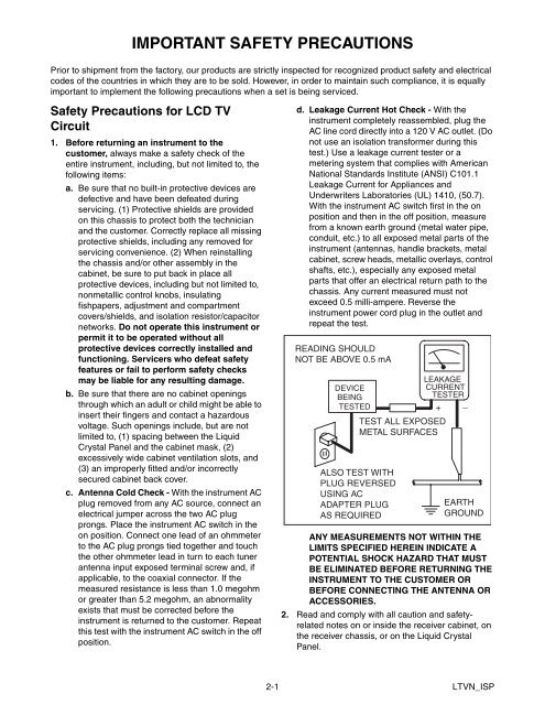
IMPORTANT SAFETY PRECAUTIONS Prior to shipment from the factory, our products are strictly inspected for recognized product safety and electrical codes of the countries in which they are to be sold. However, in order to maintain such compliance, it is equally important to implement the following precautions when a set is being serviced. Safety Precautions for LCD TV Circuit 1. Before returning an instrument to the customer, always make a safety check of the entire instrument, including, but not limited to, the following items: a. Be sure that no built-in protective devices are defective and have been defeated during servicing. (1) Protective shields are provided on this chassis to protect both the technician and the customer. Correctly replace all missing protective shields, including any removed for servicing convenience. (2) When reinstalling the chassis and/or other assembly in the cabinet, be sure to put back in place all protective devices, including but not limited to, nonmetallic control knobs, insulating fishpapers, adjustment and compartment covers/shields, and isolation resistor/capacitor networks. Do not operate this instrument or permit it to be operated without all protective devices correctly installed and functioning. Servicers who defeat safety features or fail to perform safety checks may be liable for any resulting damage. b. Be sure that there are no cabinet openings through which an adult or child might be able to insert their fingers and contact a hazardous voltage. Such openings include, but are not limited to, (1) spacing between the Liquid Crystal Panel and the cabinet mask, (2) excessively wide cabinet ventilation slots, and (3) an improperly fitted and/or incorrectly secured cabinet back cover. c. Antenna Cold Check - With the instrument AC plug removed from any AC source, connect an electrical jumper across the two AC plug prongs. Place the instrument AC switch in the on position. Connect one lead of an ohmmeter to the AC plug prongs tied together and touch the other ohmmeter lead in turn to each tuner antenna input exposed terminal screw and, if applicable, to the coaxial connector. If the measured resistance is less than 1.0 megohm or greater than 5.2 megohm, an abnormality exists that must be corrected before the instrument is returned to the customer. Repeat this test with the instrument AC switch in the off position. d. Leakage Current Hot Check - With the instrument completely reassembled, plug the AC line cord directly into a 120 V AC outlet. (Do not use an isolation transformer during this test.) Use a leakage current tester or a metering system that complies with American National Standards Institute (ANSI) C101.1 Leakage Current for Appliances and Underwriters Laboratories (UL) 1410, (50.7). With the instrument AC switch first in the on position and then in the off position, measure from a known earth ground (metal water pipe, conduit, etc.) to all exposed metal parts of the instrument (antennas, handle brackets, metal cabinet, screw heads, metallic overlays, control shafts, etc.), especially any exposed metal parts that offer an electrical return path to the chassis. Any current measured must not exceed 0.5 milli-ampere. Reverse the instrument power cord plug in the outlet and repeat the test. READING SHOULD NOT BE ABOVE 0.5 mA DEVICE BEING TESTED TEST ALL EXPOSED METAL SURFACES ALSO TEST WITH PLUG REVERSED USING AC ADAPTER PLUG AS REQUIRED LEAKAGE CURRENT TESTER + _ EARTH GROUND ANY MEASUREMENTS NOT WITHIN THE LIMITS SPECIFIED HEREIN INDICATE A POTENTIAL SHOCK HAZARD THAT MUST BE ELIMINATED BEFORE RETURNING THE INSTRUMENT TO THE CUSTOMER OR BEFORE CONNECTING THE ANTENNA OR ACCESSORIES. 2. Read and comply with all caution and safetyrelated notes on or inside the receiver cabinet, on the receiver chassis, or on the Liquid Crystal Panel. 2-1 LTVN_ISP
- Page 1 and 2: LCD TV chassis FL9.0 SERVICE MANUAL
- Page 3: TABLE OF CONTENTS Specifications .
- Page 7 and 8: Precautions during Servicing A. Par
- Page 9 and 10: Circuit Board Indications STANDARD
- Page 11 and 12: With Iron Wire: 1. Using desolderin
- Page 13 and 14: CABINET DISASSEMBLY INSTRUCTIONS [L
- Page 15 and 16: [16] Front Cabinet [13] Junction-B
- Page 17 and 18: CABINET DISASSEMBLY INSTRUCTIONS [2
- Page 19 and 20: [16] Front Cabinet (S-14) [13] Junc
- Page 21 and 22: ELECTRICAL ADJUSTMENT INSTRUCTIONS
- Page 23 and 24: The white balance adjustment should
- Page 25 and 26: Equipment Required a. USB memory b.
- Page 27 and 28: FLOW CHART NO.6 PANEL+24.5V is not
- Page 29 and 30: FLOW CHART NO.14 AL+3.3V is not out
- Page 31 and 32: FLOW CHART NO.4 Picture does not ap
- Page 33 and 34: FLOW CHART NO.3 Audio is not output
- Page 35 and 36: BLOCK DIAGRAMS System Control Block
- Page 37 and 38: Audio Block Diagram AUDIO SIGNAL JA
- Page 39 and 40: Inverter Block Diagram [LC195SLX, L
- Page 41 and 42: Power Supply Block Diagram [LC195SL
- Page 43 and 44: SCHEMATIC DIAGRAMS / CBA AND TEST P
- Page 45 and 46: Main 1/4 Schematic Diagram [LC195SL
- Page 47 and 48: Main 3/4 & Junction-B Schematic Dia
- Page 49 and 50: Main 1/4 Schematic Diagram [22MF339
- Page 51 and 52: Main 3/4 & Junction-B Schematic Dia
- Page 53 and 54: Jack & Junction-C Schematic Diagram
IMPORTANT SAFETY PRECAUTIONS<br />
Prior to shipment from the factory, our products are strictly inspected for recognized product safety and electrical<br />
codes of the countries in which they are to be sold. However, in order to maintain such compliance, it is equally<br />
important to implement the following precautions when a set is being serviced.<br />
Safety Precautions for LCD TV<br />
Circuit<br />
1. Before returning an instrument to the<br />
customer, always make a safety check of the<br />
entire instrument, including, but not limited to, the<br />
following items:<br />
a. Be sure that no built-in protective devices are<br />
defective and have been defeated during<br />
servicing. (1) Protective shields are provided<br />
on this chassis to protect both the technician<br />
and the customer. Correctly replace all missing<br />
protective shields, including any removed for<br />
servicing convenience. (2) When reinstalling<br />
the chassis and/or other assembly in the<br />
cabinet, be sure to put back in place all<br />
protective devices, including but not limited to,<br />
nonmetallic control knobs, insulating<br />
fishpapers, adjustment and compartment<br />
covers/shields, and isolation resistor/capacitor<br />
networks. Do not operate this instrument or<br />
permit it to be operated without all<br />
protective devices correctly installed and<br />
functioning. Servicers who defeat safety<br />
features or fail to perform safety checks<br />
may be liable for any resulting damage.<br />
b. Be sure that there are no cabinet openings<br />
through which an adult or child might be able to<br />
insert their fingers and contact a hazardous<br />
voltage. Such openings include, but are not<br />
limited to, (1) spacing between the Liquid<br />
Crystal Panel and the cabinet mask, (2)<br />
excessively wide cabinet ventilation slots, and<br />
(3) an improperly fitted and/or incorrectly<br />
secured cabinet back cover.<br />
c. Antenna Cold Check - With the instrument AC<br />
plug removed from any AC source, connect an<br />
electrical jumper across the two AC plug<br />
prongs. Place the instrument AC switch in the<br />
on position. Connect one lead of an ohmmeter<br />
to the AC plug prongs tied together and touch<br />
the other ohmmeter lead in turn to each tuner<br />
antenna input exposed terminal screw and, if<br />
applicable, to the coaxial connector. If the<br />
measured resistance is less than 1.0 megohm<br />
or greater than 5.2 megohm, an abnormality<br />
exists that must be corrected before the<br />
instrument is returned to the customer. Repeat<br />
this test with the instrument AC switch in the off<br />
position.<br />
d. Leakage Current Hot Check - With the<br />
instrument completely reassembled, plug the<br />
AC line cord directly into a 120 V AC outlet. (Do<br />
not use an isolation transformer during this<br />
test.) Use a leakage current tester or a<br />
metering system that complies with American<br />
National Standards Institute (ANSI) C101.1<br />
Leakage Current for Appliances and<br />
Underwriters Laboratories (UL) 1410, (50.7).<br />
With the instrument AC switch first in the on<br />
position and then in the off position, measure<br />
from a known earth ground (metal water pipe,<br />
conduit, etc.) to all exposed metal parts of the<br />
instrument (antennas, handle brackets, metal<br />
cabinet, screw heads, metallic overlays, control<br />
shafts, etc.), especially any exposed metal<br />
parts that offer an electrical return path to the<br />
chassis. Any current measured must not<br />
exceed 0.5 milli-ampere. Reverse the<br />
instrument power cord plug in the outlet and<br />
repeat the test.<br />
READING SHOULD<br />
NOT BE ABOVE 0.5 mA<br />
DEVICE<br />
BEING<br />
TESTED<br />
TEST ALL EXPOSED<br />
METAL SURFACES<br />
ALSO TEST WITH<br />
PLUG REVERSED<br />
USING AC<br />
ADAPTER PLUG<br />
AS REQUIRED<br />
LEAKAGE<br />
CURRENT<br />
TESTER<br />
+ _<br />
EARTH<br />
GROUND<br />
ANY MEASUREMENTS NOT WITHIN THE<br />
LIMITS SPECIFIED HEREIN INDICATE A<br />
POTENTIAL SHOCK HAZARD THAT MUST<br />
BE ELIMINATED BEFORE RETURNING THE<br />
INSTRUMENT TO THE CUSTOMER OR<br />
BEFORE CONNECTING THE ANTENNA OR<br />
ACCESSORIES.<br />
2. Read and comply with all caution and safetyrelated<br />
notes on or inside the receiver cabinet, on<br />
the receiver chassis, or on the Liquid Crystal<br />
Panel.<br />
2-1 LTVN_ISP


