SUSPENSION – FRONT - CelicaTech
SUSPENSION – FRONT - CelicaTech
SUSPENSION – FRONT - CelicaTech
You also want an ePaper? Increase the reach of your titles
YUMPU automatically turns print PDFs into web optimized ePapers that Google loves.
<strong>SUSPENSION</strong> - <strong>FRONT</strong><br />
1988 Toyota Celica<br />
<strong>FRONT</strong> <strong>SUSPENSION</strong><br />
Toyota<br />
DESCRIPTION<br />
Vehicles are equipped with front wheel drive and independent<br />
MacPherson strut front suspension. Suspension consists of vertically<br />
mounted strut assemblies, control arms and a stabilizer bar.<br />
Struts are mounted between the inner fender and steering<br />
knuckle. Tie rod ends connect rack and pinion steering to steering<br />
knuckle. A ball joint connects the steering knuckle to lower control<br />
arm which attaches to frame crossmember. Stabilizer bar attaches to<br />
lower control arms and 2 points on the crossmember. On Camry and<br />
Tercel, the stabilizer bar acts as a strut rod and permits caster<br />
adjustment.<br />
Fig. 1: Tercel Front Suspension Components<br />
Courtesy of Toyota Motor Sales, U.S.A., Inc.<br />
ADJUSTMENTS & INSPECTION<br />
WHEEL ALIGNMENT SPECIFICATIONS & PROCEDURES<br />
See WHEEL ALIGNMENT SPECIFICATIONS & PROCEDURES in WHEEL<br />
ALIGNMENT section.<br />
WHEEL BEARING<br />
Wheel bearings are not adjustable. Whenever bearings are<br />
removed, replace with new bearings, races, and oil seals.
BALL JOINT CHECKING<br />
1) Raise vehicle and place a wooden block with a height of<br />
7.09-7.87" (180.0-200.0 mm) under one front tire. Lower floor jack<br />
until there is about half the load of the vehicle on front struts.<br />
Place safety stands under vehicle.<br />
2) Position front wheels straight ahead and block them. Use<br />
a rod to move control arm up and down. Check for vertical ball joint<br />
play. Ball joints are serviceable as a unit only. If damaged or any<br />
vertical play is found, replace ball joint.<br />
REMOVAL & INSTALLATION<br />
WHEEL BEARING<br />
Removal<br />
1) Remove cotter pin, bearing lock nut cap and bearing lock<br />
nut (apply brakes when removing lock nut). Remove brake caliper. Do<br />
not disconnect brake line. Secure caliper out of the way. Remove disc<br />
brake rotor. Remove cotter pin and castle nut from tie rod end.<br />
2) Using Puller (09950-20016) for Camry and Corolla models,<br />
Puller (09610-20012) for Tercel models, or Puller (09628-62011) for<br />
Celica models, pull tie rod end from steering knuckle. Place<br />
reference marks on lower strut bracket and camber adjusting cam.<br />
3) Remove bolts and nuts to separate steering knuckle and<br />
strut. On Camry and Tercel models, remove 2 bolts holding ball joint<br />
to steering knuckle and separate. On Celica and Corolla models,<br />
remove 1 bolt and 2 nuts, and separate lower arm from steering<br />
knuckle.<br />
4) On all models, use puller to pull axle hub from drive<br />
shaft. Cover drive boot with a cloth to prevent damage. On Celica and<br />
Corolla models, use Puller (09610-55012) to remove the ball joint<br />
from the steering knuckle.<br />
5) Place steering knuckle in a vise and remove dust<br />
deflector. Using Seal Puller (09308-00010), pull inner oil seal out<br />
of steering knuckle. Remove snap ring from steering knuckle hole.<br />
6) Remove the 3 bolts holding the disc brake dust cover to<br />
the steering knuckle. Using puller, push axle hub from steering<br />
knuckle. Remove disc brake dust cover. On models equipped with ABS,<br />
remove speed sensor rotor from axle hub. Remove inside inner bearing<br />
race. Using puller, remove outside inner race from axle hub. Pull<br />
outer oil seal from steering knuckle.<br />
7) On all models, install old outside inner race on bearing.<br />
On Tercel models, use Fixture (09228-22020) and an arbor press to<br />
remove bearing from steering knuckle. On all other models, use Driver<br />
(09605-60010) and a hammer to remove bearing.
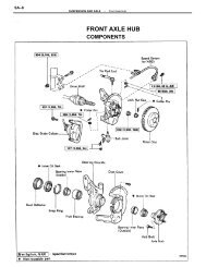
Fig. 2: Camry, Celica & Corolla Axle Hub Components<br />
Courtesy of Toyota Motor Sales, U.S.A., Inc.<br />
CAUTION: Always replace bearings and races as an assembly.<br />
Installation<br />
1) On Camry, Celica and Corolla models use an arbor press and
Seal Driver (09608-32010) to press new bearing into steering knuckle.<br />
On Tercel models, use Bearing Driver (09309-35010) to press new<br />
bearing into steering knuckle. Place outside inner bearing race on<br />
outside bearing.<br />
2) Using seal driver and Bushing Driver (09710-14012) for<br />
Camry, Celica and Corolla models, or Seal Driver (09515-35010) for<br />
Tercel models, drive new outer oil seal into steering knuckle. Apply<br />
sealer to dust cover and steering knuckle connection and assemble.<br />
3) On models equipped with ABS, install speed sensor rotor<br />
onto axle hub. Use Bearing Driver (09310-35010) to press hub into<br />
steering knuckle. Do not interchange the inner and outer races on<br />
Tercel models. Install snap ring into hole of steering knuckle on all<br />
models.<br />
4) Using seal driver and Bushing Driver (09710-14012) for<br />
Camry, Celica and Corolla models, drive new oil seal flush to the end<br />
surface of steering knuckle. On Tercel models, use Seal Driver<br />
(09309-35010) to drive inner oil seal .130" (3.3 mm) below the end<br />
surface of steering knuckle.<br />
5) On Camry models, use Seal Driver (09223-41020) to drive<br />
new dust deflector into steering knuckle. On Tercel models, use Seal<br />
Driver (09608-16050). On Corolla models, use Seal Driver<br />
(09218-46010). On Celica models, use Seal Driver (09608-35014).<br />
6) On Celica and Corolla models, seat ball joint to steering<br />
knuckle by tightening old nut to 14 ft. lbs. (20 N.m). Remove the<br />
nut, and install a new nut. Tighten the new nut to specification.<br />
7) On all models, install steering knuckle with axle hub to<br />
driveshaft with the washer and nut. Do not tighten the nut. Tighten<br />
steering knuckle-to-control arm on Camry and Tercel models to<br />
specification. Tighten ball joint-to-lower control arm on Corolla and<br />
Celica models to specification.<br />
8) Align reference marks of camber adjusting cam-to-strut.<br />
Install steering knuckle to strut. Tighten and torque to<br />
specifications.<br />
NOTE:<br />
Camry and Corolla model strut bolts are installed from the<br />
rear side. Celica and Tercel model strut bolts are installed<br />
from the front side.<br />
9) Install disc rotor to axle hub. Tighten and torque brake<br />
caliper to steering knuckle bolts to specifications. Install tie rod<br />
end to steering knuckle. Tighten to specification. To install wheel<br />
bearing lock nut, apply brakes and tighten axle nut on all models to<br />
137 ft. lbs. (186 N.m). Install nut lock cap and new cotter pin.<br />
Check wheel alignment.<br />
Fig. 3: Camry Lower Control Arm & Stabilizer<br />
Courtesy of Toyota Motor Sales, U.S.A., Inc.
Fig. 4: Corolla Lower Control Arm & Stabilizer<br />
Courtesy of Toyota Motor Sales, U.S.A., Inc.
Fig. 5: Celica Lower Control Arm & Stabilizer<br />
Courtesy of Toyota Motor Sales, U.S.A., Inc.<br />
CONTROL ARM & BALL JOINT<br />
Removal<br />
1) Raise vehicle and support with jackstands. On Tercel and<br />
Camry models remove 2 bolts holding ball joint to steering knuckle and<br />
separate. On Celica and Corolla models remove 1 bolt and 2 nuts<br />
holding the ball joint to the control arm and separate. On Celica<br />
models, remove nut and disconnect stabilizer link from lower arm. On<br />
all other models, remove stabilizer bar nut, retainer and cushion from
lower arm.<br />
2) On Celica and Corolla models remove 2 bolts holding the<br />
lower arm rear brackets to the frame. Loosen the lower arm bolt<br />
(Corolla) or nut and washer (Celica) and remove lower arm. On Celica<br />
models only, remove suspension lower crossmember and lower arm shaft.<br />
NOTE:<br />
On Celica models equipped with automatic transmission, left<br />
side lower control arm must be removed together with lower<br />
arm shaft. Remove suspension lower crossmember first before<br />
removing lower arm and shaft assembly.<br />
3) On Camry and Tercel models, loosen the lower arm bolt.<br />
Pry on arm and pull out bolt. Disconnect lower arm from stabilizer.<br />
Be careful not to lose the caster adjusting spacer.<br />
NOTE:<br />
On Tercel models, jack up the opposite wheel to remove lower<br />
arm.<br />
4) To remove ball joint from lower arm, use ball joint<br />
puller. Temporarily install nut to prevent ball joint from falling<br />
out of control arm when removing.<br />
Installation<br />
1) Reverse removal procedure. Tighten ball joint nut to<br />
specification. Replace cotter pin.<br />
2) On all models except Celica, install control arm and<br />
finger tighten the bolts and the stabilizer nut. Tighten ball joint<br />
to steering knuckle on Camry and Tercel models to specification.<br />
Tighten ball joint to lower arm on Corolla models to specification.<br />
3) On Celica models, install lower arm shaft or lower arm<br />
shaft/control arm assembly and tighten shaft nut and bolt to<br />
specification. Ensure shaft washer tapered side faces body. Install<br />
lower suspension crossmember and tighten the fasteners to<br />
specification. Tighten ball joint to lower control arm to<br />
specification. Finger tighten lower arm nut, rear bracket bolts and<br />
stabilizer bar link nut.<br />
4) Install wheels and lower vehicle. Bounce vehicle to<br />
settle the suspension. Tighten stabilizer bar nut to specification.<br />
Tighten lower arm bolts on Camry and Tercel models to specification.<br />
Tighten Corolla lower arm rear bracket bolts and lower arm bolt to<br />
specification. Tighten Celica lower arm nut and lower arm rear<br />
bracket bolts to specification. Check alignment.<br />
CONTROL ARM BUSHING<br />
Removal (Camry & Tercel)<br />
1) Before removing control arm bushing, cut off excess rubber<br />
from flange. Using a hammer and a chisel, bend bushing flange inward.<br />
2) Using a pair of pliers, bend and break off flange. Using<br />
an arbor press and Fixture (09726-32010), press bushing from control<br />
arm.<br />
Installation (Camry & Tercel)<br />
When installing control arm bushing, there must be no oil or<br />
grease on bushing or arm boss. Using an arbor press and Fixture<br />
(09726-32010), press bushing into control arm boss.<br />
Removal (Celica & Corolla)<br />
On a vise. Remove nut, retainer and bushing from control arm.<br />
Installation (Celica & Corolla)<br />
Install new bushing, retainer and nut. Tighten nut to<br />
specification.
STRUT ASSEMBLY<br />
Removal<br />
1) On Camry and Corolla models only, disconnect brake tube<br />
from flexible brake hose. Drain brake fluid into a container. Remove 2<br />
clips and 2 "E" rings. Remove 2 bolts from the brake caliper and<br />
remove the caliper. Do not disconnect the flexible brake hose from the<br />
caliper assembly.<br />
2) On Celica models, remove union bolt and 2 washers and<br />
disconnect brake hose from disc brake caliper. Drain fluid into a<br />
container. Remove clip from brake hose and pull off hose from bracket.<br />
3) On all models, place reference marks on strut lower<br />
bracket and camber adjusting cam. Remove the 2 nuts and bolts and<br />
separate strut from steering knuckle.<br />
4) Remove dust cover from top of strut. Loosen strut support<br />
nut on Tercel models only. On all models, remove 3 nuts holding top<br />
of strut to body. Remove strut from vehicle.<br />
CAUTION: When removing strut, cover drive shaft boot with a cloth<br />
for protection.<br />
Disassembly<br />
1) Install a bolt and 2 nuts to the strut lower bracket to<br />
prevent distortion of strut shell when clamped. Clamp bottom of strut<br />
in a vise.<br />
2) Using Compressor (09727-22032), compress coil spring.<br />
Hold the spring seat with Lever (09729-22031) and remove strut rod<br />
top nut. Remove components.<br />
Inspection (Corolla)<br />
Inspect for leaks or damage. Pull up shock absorber piston<br />
rod at a constant rate to see if tension is even throughout length of<br />
pull. Rapidly move piston up and down .20-.39" (5.0-10.0 mm) to see if<br />
there is a change in tension. If shock is defective, replace as an<br />
assembly.<br />
Inspection (Camry, Celica & Tercel)<br />
Inspect for leaks or damage. Push the piston rod in fully and<br />
release it. The rod should return at a constant speed throughout the<br />
stroke. Check for abnormal resistance or noise when compressing the<br />
rod. If shock is defective, replace as an assembly.<br />
CAUTION: Be sure and discharge the gas in the shock by loosening the<br />
ring nut 2 or 3 turns before discarding. Use Shock Absorber<br />
Wrench (09720-00011) on ring nut.<br />
Installation<br />
1) To install, reverse removal procedure. On Celica, Corolla<br />
and Camry models, ensure "OUT" mark on spring seat faces towards the<br />
outside of the vehicle. On Celica, Corolla and Camry models, tighten<br />
support nut to specification. On Tercel models, install nut but do not<br />
tighten.<br />
2) Install strut to body. Tighten and torque the 3 nuts to<br />
specification.<br />
3) Install strut to steering knuckle and tighten bolts. See<br />
step 8) in WHEEL BEARING INSTALLATION in this article.<br />
4) On Tercel, tighten support nut to specification. On all<br />
models, install dust cover after packing bearing in suspension<br />
support with grease. Bleed brakes. On Celica models, ensure flexible<br />
brake hose peg aligns with caliper hole. On all models, check front<br />
end alignment. See WHEEL ALIGNMENT section.
STABILIZER BAR<br />
Removal (Camry)<br />
Remove covers below engine. Remove the 2 hole covers and the<br />
8 bolts from the center engine mounting members. Remove stabilizer<br />
brackets from body. Disconnect bar from lower arms. Note positions of<br />
bushings and spacers. Remove the stabilizer bar. It may be necessary<br />
to remove one of the lower control arms to remove stabilizer.<br />
Fig. 6: Camry & Corolla Shock Avsorber<br />
Courtesy of Toyota Motor Sales, U.S.A. Inc.<br />
Removal (Celica)<br />
Disconnect stabilizer link from lower arm and stabilizer bar.
Remove both brackets from body. On models equipped with 4WD, mark<br />
driveshaft flange for installation reference and remove drive shaft.<br />
Disconnect exhaust pipe from manifold. Disconnect exhaust pipe from<br />
tail pipe hanger ring. Remove stabilizer bar. Inspect stabilizer link<br />
ball joint arms. If movement of arms is not free in all directions,<br />
replace stabilizer link.<br />
Removal (Corolla)<br />
Disconnect bar from lower arms. Remove brackets from body.<br />
Disconnect exhaust pipe from exhaust manifold. Remove stabilizer.<br />
Removal (Tercel)<br />
Remove covers below engine. Remove brackets from crossmember.<br />
Disconnect both ends from lower arms, noting positions of bushings and<br />
spacers. Remove stabilizer bar.<br />
Installation (All Models)<br />
To install, reverse removal procedure. On Camry, tighten<br />
center engine mounting member bolts to 29 ft. lbs. (39 N.m). On all<br />
models, check wheel alignment. See WHEEL ALIGNMENT section.<br />
TORQUE SPECIFICATIONS<br />
TIGHTENING SPECIFICATIONS TABLE<br />
¡¡¡¡¡¡¡¡¡¡¡¡¡¡¡¡¡¡¡¡¡¡¡¡¡¡¡¡¡¡¡¡¡¡¡¡¡¡¡¡¡¡¡¡¡¡¡¡¡¡¡¡¡¡¡¡¡¡¡¡¡¡¡¡¡¡¡¡<br />
¡<br />
Application<br />
Ft. Lbs. (N.m)<br />
Camry<br />
Axle Shaft Flange Bolts<br />
4WD ..................................................... 48 (65)<br />
2WD ..................................................... 27 (36)<br />
Axle Nut ............................................... 137 (186)<br />
Ball Joint-to-Control Arm Nut ............................ 67 (91)<br />
Ball Joint-to-Knuckle Bolts ............................. 94 (127)<br />
Brake Caliper Bolts ..................................... 86 (117)<br />
Control Arm-to-Body Bolt ............................... 156 (212)<br />
Control Arm-to-Steering Knuckle ........................ 156 (212)<br />
Stabilizer Bar Bracket Bolts ............................ 94 (127)<br />
Stabilizer-to-Control Arm Nut ........................... 86 (117)<br />
Steering Knuckle-to-Strut .............................. 166 (226)<br />
Strut Assembly Top Support Nut ........................... 34 (47)<br />
Strut Assembly-to-Body Nuts .............................. 47 (64)<br />
Tie Rod End-to-Steering Knuckle .......................... 36 (49)<br />
Celica<br />
Axle Shaft Flange Bolts<br />
4WD ..................................................... 48 (65)<br />
2WD ..................................................... 27 (36)<br />
Axle Nut ............................................... 137 (186)<br />
Ball Joint-to-Knuckle Nut ............................... 82 (111)<br />
Ball Joint-to-Lower Arm ................................. 94 (127)<br />
Brake Caliper-to-Knuckle ................................. 70 (95)<br />
Brake Hose-to-Caliper .................................... 22 (30)<br />
Control Arm Bushing Nut ................................. 76 (103)<br />
Control Arm Bracket-to-Body .............................. 72 (98)<br />
Crossmember Bolts (4) .................................. 156 (212)<br />
Crossmember Nuts (2) ..................................... 29 (39)<br />
Drive Shaft Flange Bolts ................................. 54 (74)<br />
Exhaust Pipe-to-Manifold ................................. 46 (62)<br />
Exhaust Pipe-to-Tail Pipe ................................ 32 (43)<br />
Knuckle-to-Strut ....................................... 152 (206)<br />
Lower Arm Shaft-to-Body ................................ 154 (208)<br />
Lower Arm Nut .......................................... 156 (212)
Stabilizer Link-to-<br />
Lower Arm & Bar ......................................... 26 (35)<br />
Stabilizer Bracket-to-Body ............................... 14 (19)<br />
Strut Assembly Top Support Nut ........................... 34 (47)<br />
Strut Assembly-to-Body Nuts .............................. 47 (64)<br />
Tie Rod-to-Knuckle ....................................... 36 (49)<br />
Corolla<br />
Axle Shaft Flange Bolts .................................. 27 (36)<br />
Axle Nut ............................................... 137 (186)<br />
Ball Joint-to-Steering Knuckle .......................... 82 (111)<br />
Ball Joint-to-Control Arm ................................ 47 (64)<br />
Brake Caliper Bolts ...................................... 65 (88)<br />
Control Arm Bracket-to-Body Bolts ........................ 64 (87)<br />
Control Arm-to-Body Bolt ............................... 105 (142)<br />
Control Arm Bushing Nut ................................. 76 (103)<br />
Stabilizer Bar Nut ....................................... 13 (18)<br />
Steering Knuckle-to-Strut .............................. 105 (142)<br />
Strut Assembly Top Support Nut ........................... 34 (47)<br />
Strut Assembly-to-Body Nuts .............................. 23 (31)<br />
Stabilizer Bracket Bolts ................................. 14 (19)<br />
Tie Rod End-to-Steering Knuckle .......................... 36 (49)<br />
Tercel<br />
Axle Nut ............................................... 137 (186)<br />
Ball Joint-to-Control Arm Nut ............................ 59 (80)<br />
Ball Joint-to-Knuckle Bolts .............................. 59 (80)<br />
Brake Caliper Bolts ...................................... 70 (95)<br />
Control Arm-to-Body Bolt ............................... 105 (142)<br />
Stabilizer Bar Bracket Bolts ............................. 32 (44)<br />
Stabilizer-to-Control Arm Nut ........................... 78 (105)<br />
Steering Knuckle-to-Strut .............................. 105 (142)<br />
Strut Assembly Top Support Nut ........................... 34 (47)<br />
Strut Assembly-to-Body Nuts .............................. 23 (31)<br />
Tie Rod End-to-Steering Knuckle .......................... 36 (49)<br />
¡ ¡ ¡ ¡ ¡ ¡ ¡ ¡ ¡ ¡ ¡ ¡ ¡ ¡ ¡ ¡ ¡ ¡ ¡ ¡ ¡ ¡ ¡ ¡ ¡ ¡ ¡ ¡ ¡ ¡ ¡ ¡ ¡ ¡ ¡ ¡ ¡ ¡ ¡ ¡ ¡ ¡ ¡ ¡ ¡ ¡ ¡ ¡ ¡ ¡ ¡ ¡ ¡ ¡ ¡ ¡ ¡ ¡ ¡ ¡ ¡ ¡ ¡ ¡ ¡ ¡ ¡ ¡ ¡


