Niles CM710FX CM750FX surround in-ceiling speaker Installation
Niles CM710FX CM750FX surround in-ceiling speaker Installation
Niles CM710FX CM750FX surround in-ceiling speaker Installation
You also want an ePaper? Increase the reach of your titles
YUMPU automatically turns print PDFs into web optimized ePapers that Google loves.
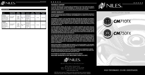
SPECIFICATIONS<br />
Model<br />
<strong>CM710FX</strong><br />
7" polypropylene woofer<br />
with treated urethane<br />
<strong>surround</strong> and one fluidcooled<br />
13mm Kaladex.<br />
<strong>CM750FX</strong><br />
7" Injection-molded<br />
TCC woofer with<br />
butyl rubber <strong>surround</strong><br />
and two pivot<strong>in</strong>g 1”<br />
Teteron ® tweeters with<br />
fluid cool<strong>in</strong>g.<br />
Recommended<br />
Amplifier Power<br />
10 to 75 watts<br />
per channel<br />
10 to 125 watts<br />
per channel<br />
Normal<br />
Impedance<br />
8 ohm<br />
nom<strong>in</strong>al;<br />
6 ohm<br />
m<strong>in</strong>imum<br />
8 ohm<br />
nom<strong>in</strong>al;<br />
6 ohm<br />
m<strong>in</strong>imum<br />
Frequency<br />
Response<br />
60Hz - 21kHz<br />
+/-3dB<br />
55Hz - 21kHz<br />
+/-3dB<br />
Sensitivity<br />
90 dB with<br />
2.83 V p<strong>in</strong>k<br />
noise <strong>in</strong>put<br />
measured<br />
at 1 meter<br />
on axis<br />
89 dB with<br />
2.83 V p<strong>in</strong>k<br />
noise <strong>in</strong>put<br />
measured<br />
at 1 meter<br />
on axis<br />
Frame<br />
Dimensions<br />
Hole Cut-Out<br />
Dimensions<br />
Depth Beh<strong>in</strong>d<br />
Ceil<strong>in</strong>g<br />
9-1/4 <strong>in</strong>ches 8 <strong>in</strong>ches 4-3/8 <strong>in</strong>ches<br />
9-1/4 <strong>in</strong>ches 8 <strong>in</strong>ches 4-3/8 <strong>in</strong>ches<br />
TECHNICAL SUPPORT<br />
IF YOU HAVE QUESTIONS ABOUT THE INSTALLATION OR OPERATION OF THIS OR ANY OTHER NILES PRODUCT,<br />
PLEASE CALL OUR TECHNICAL SUPPORT DEPARTMENT AT 1-800-BUY-HIFI (1-800-289-4434). SUPPORT IS<br />
AVAILABLE WEEKDAYS 8:00 A.M. TO 7:00 P.M. EASTERN TIME WITH THE EXCEPTION OF HOLIDAYS.<br />
LIMITED WARRANTY<br />
NILES AUDIO CORPORATION (“NILES”) WARRANTS ITS LOUDSPEAKER PRODUCTS TO THE ORIGINAL PURCHASER TO<br />
BE FREE OF MANUFACTURING DEFECTS IN MATERIAL AND WORKMANSHIP FOR A PERIOD OF FIVE YEARS FROM<br />
DATE OF PURCHASE.<br />
THIS WARRANTY IS SUBJECT TO THE FOLLOWING ADDITIONAL CONDITIONS AND LIMITATIONS. THE WARRANTY<br />
IS VOID AND INAPPLICABLE IF NILES DEEMS THAT THE PRODUCT HAS BEEN USED OR HANDLED OTHER THAN IN<br />
ACCORDANCE WITH THE INSTRUCTIONS PROVIDED BY THE MANUFACTURER, INCLUDING BUT NOT LIMITED TO<br />
DAMAGE CAUSED BY ACCIDENT, MISHANDLING, IMPROPER INSTALLATION, ABUSE, NEGLIGENCE, OR NORMAL<br />
WEAR AND TEAR, OR ANY DEFECT CAUSED BY REPAIR TO THE PRODUCT BY ANYONE OTHER THAN NILES OR AN<br />
AUTHORIZED NILES DEALER.<br />
TO OBTAIN WARRANTY SERVICE, TAKE THE UNIT TO THE NEAREST AUTHORIZED NILES DEALER, WHO WILL<br />
TEST THE PRODUCT AND IF NECESSARY, FORWARD IT TO NILES FOR SERVICE. IF THERE ARE NO AUTHORIZED<br />
NILES DEALERS IN YOUR AREA, YOU MUST WRITE TO NILES AND INCLUDE YOUR NAME, ADDRESS, MODEL AND<br />
SERIAL NUMBER OF YOUR UNIT, ALONG WITH A BRIEF DESCRIPTION OF THE PROBLEM. A FACTORY RETURN<br />
AUTHORIZATION NUMBER WILL BE SENT TO YOU. DO NOT RETURN ANY UNIT WITHOUT FIRST RECEIVING WRITTEN<br />
AUTHORIZATION AND SHIPPING INSTRUCTIONS FROM NILES.<br />
IF THE ABOVE CONDITIONS ARE MET, THE PURCHASER’S SOLE REMEDY SHALL BE TO RETURN THE PRODUCT TO<br />
NILES, IN WHICH CASE NILES WILL REPAIR OR REPLACE, AT ITS SOLE OPTION, THE DEFECTIVE PRODUCT WITHOUT<br />
CHARGE FOR PARTS OR LABOR. NILES WILL RETURN A UNIT REPAIRED OR REPLACED UNDER WARRANTY BY<br />
SHIPPING SAME BY ITS USUAL SHIPPING METHOD FROM THE FACTORY (ONLY) AT ITS EXPENSE WITHIN THE<br />
UNITED STATES OF AMERICA. THERE ARE NO OTHER WARRANTIES, INCLUDING WITHOUT LIMITATION, EITHER<br />
EXPRESS OR IMPLIED WARRANTIES OF MERCHANTABILITY OR FITNESS FOR A PARTICULAR PURPOSE, WITH<br />
RESPECT TO THE PRODUCT.<br />
REPAIR OR REPLACEMENT AS PROVIDED UNDER THIS WARRANTY IS THE EXCLUSIVE REMEDY OF THE CONSUMER/<br />
PURCHASER. NILES SHALL NOT BE RESPONSIBLE FOR ANY INCIDENTAL OR CONSEQUENTIAL DAMAGES EXCEPT TO<br />
THE EXTENT PROVIDED (OR PROHIBITED) BY APPLICABLE LAW.<br />
SOME STATES DO NOT ALLOW THE EXCLUSION OR LIMITATION OF INCIDENTAL OR CONSEQUENTIAL DAMAGES,<br />
SO THE ABOVE LIMITATION MAY NOT APPLY TO YOU. THIS WARRANTY GIVES YOU SPECIFIC LEGAL RIGHTS, AND<br />
YOU MAY ALSO HAVE OTHER RIGHTS WHICH VARY FROM STATE TO STATE.<br />
FOR THE NAME OF YOUR NEAREST AUTHORIZED NILES DEALER CONTACT:<br />
NILES AUDIO CORPORATION, P.O. BOX 160818, MIAMI, FLORIDA 33116-0818.<br />
B L E N D I N G H I G H F I D E L I T Y A N D A R C H I T E C T U R E ®<br />
N i l e s A u d i o C o r p o r a t i o n<br />
1 2 3 3 1 S . W . 1 3 0 S t r e e t M i a m i , F l o r i d a 3 3 1 8 6<br />
P h o n e : 3 0 5 - 2 3 8 - 4 3 7 3 F a x : ( 3 0 5 ) 2 3 8 - 0 1 8 5<br />
w w w . n i l e s a u d i o . c o m<br />
©2007 <strong>Niles</strong> Audio Corporation. All rights reser ved. <strong>Niles</strong> and the <strong>Niles</strong> logos are registered trademarks<br />
of <strong>Niles</strong> Audio Corporation. All other trademarks are the property of their respective owners. D S 0 0 5 3 6 A<br />
I N S T A L L A T I O N G U I D E<br />
<strong>CM710FX</strong><br />
<strong>CM750FX</strong><br />
H I G H P E R F O R M A N C E C E I L I N G L O U D S P E A K E R S
CONGRATULATIONS!<br />
Thank you for choos<strong>in</strong>g a <strong>CM710FX</strong> or <strong>CM750FX</strong> loud<strong>speaker</strong> from <strong>Niles</strong>. With proper <strong>in</strong>stallation and operation, you will enjoy years of<br />
trouble-free use. <strong>Niles</strong> manufactures the <strong>in</strong>dustry’s most complete l<strong>in</strong>e of custom <strong>in</strong>stallation components and accessories for audio/video<br />
systems. To see the complete <strong>Niles</strong> product assortment, visit us on the Internet at: www.nilesaudio.com<br />
PACKAGE CONTENTS<br />
Each package conta<strong>in</strong>s a pair of <strong>CM710FX</strong> or <strong>CM750FX</strong> loud<strong>speaker</strong>s; 1 pair of Alum<strong>in</strong>um MicroPerf Grilles and 1 pair of cardboard pa<strong>in</strong>t<br />
mask/hole cutout templates.<br />
INSTALLATION CONSIDERATIONS<br />
We recommend us<strong>in</strong>g the follow<strong>in</strong>g tools and material to <strong>in</strong>stall your <strong>Niles</strong> CM loud<strong>speaker</strong>:<br />
• Cordless drill with 1/4 – and 1/2<strong>in</strong>ch<br />
drill bits and a 1-<strong>in</strong>ch paddle<br />
drill bit (for drill<strong>in</strong>g through studs)<br />
• Stiff wire, fish tape or glow rods<br />
for rout<strong>in</strong>g cables<br />
• Rubber gloves and protective<br />
eyewear<br />
Before start<strong>in</strong>g the <strong>in</strong>stallation, please observe the follow<strong>in</strong>g precautions:<br />
• Turn off all system power before<br />
mak<strong>in</strong>g any connections<br />
• Always wear protective eyewear<br />
when us<strong>in</strong>g tools<br />
RUNNING WIRES IN WALLS OR CEILINGS<br />
• Keyhole or drywall saw<br />
• Phillips screwdriver set<br />
• Wire stripper<br />
• Stud f<strong>in</strong>der<br />
• Cable ties<br />
• Pencil<br />
When runn<strong>in</strong>g loud<strong>speaker</strong> wire <strong>in</strong>side walls or ceil<strong>in</strong>gs, use special jacketed cable (a m<strong>in</strong>imum of 18 to 16-gauge two-conductor CL-2<br />
or CL-3 rated loud<strong>speaker</strong> wire) to protect the wire and for fire prevention. In some areas, conduit is also required. For a trouble-free<br />
<strong>in</strong>stallation, low-voltage wire such as loud<strong>speaker</strong> wire must be run <strong>in</strong> accordance with the National Electrical Code and any applicable<br />
provisions of the local build<strong>in</strong>g code. If you are unsure of the correct <strong>in</strong>stallation techniques, wire jacket, or type of conduit to use, consult a<br />
professional audio/video <strong>in</strong>staller, build<strong>in</strong>g contractor, or the local build<strong>in</strong>g and <strong>in</strong>spection department.<br />
SELECTING THE LOCATION FOR YOUR LOUDSPEAKERS<br />
The CM700FX series loud<strong>speaker</strong>s are designed to be <strong>in</strong>stalled <strong>in</strong> any standard ceil<strong>in</strong>g. There are two considerations for plac<strong>in</strong>g the<br />
loud<strong>speaker</strong>; ease of runn<strong>in</strong>g the cable to the loud<strong>speaker</strong> and coverage of the loud<strong>speaker</strong>. The <strong>surround</strong> effect will be most conv<strong>in</strong>c<strong>in</strong>g<br />
if both of the loud<strong>speaker</strong>s are at equal distance from the listener. Avoid <strong>in</strong>stall<strong>in</strong>g the loud<strong>speaker</strong>s near corners to prevent a “boomy” or<br />
diffracted sound. The loud<strong>speaker</strong>s will cover an area of a circle with a 16-foot diameter when mounted at an 8-foot height. (See Figure 1)<br />
EXISTING CONSTRUCTION INSTALLATION<br />
• Make sure hands are clean before<br />
<strong>in</strong>stallation<br />
• Wear gloves when work<strong>in</strong>g with<br />
fiberglass <strong>in</strong>sulation<br />
IMPORTANT: BEFORE YOU CUT INTO ANY WALL, REVIEW THE PRIOR SECTION ON LOUDSPEAKER PLACEMENT WHEN SELECTING THE<br />
LOCATION FOR YOUR LOUDSPEAKERS.<br />
1. When determ<strong>in</strong><strong>in</strong>g the location of the loud<strong>speaker</strong> cutout, keep <strong>in</strong> m<strong>in</strong>d that the mount<strong>in</strong>g dogs will extend 3/4” beyond the cutout.<br />
Make sure that you do not place the edge of the cutout directly next to a ceil<strong>in</strong>g joist. Locate the joists us<strong>in</strong>g a stud sensor or by hand<br />
knock<strong>in</strong>g. Use the supplied cutout template (remove the largest perforated circle and use cardboard square with hole as the template) to<br />
determ<strong>in</strong>e how large of a hole you will need to cut. These templates are packed with your loud<strong>speaker</strong>s between the styrofoam pack<strong>in</strong>g<br />
and the ends of the box.<br />
2. Once you have determ<strong>in</strong>ed a possible position for the cutout, drill a 1/8” pilot hole just barely through the ceil<strong>in</strong>g (1/2” to 5/8” deep <strong>in</strong><br />
most homes) <strong>in</strong> the center of your proposed loud<strong>speaker</strong> location.<br />
BE VERY CAREFUL NOT TO DRILL THROUGH EXISTING WIRES, PIPES, OR STRUCTURE. IF YOU FEEL ANY EXTRA RESISTANCE AS YOU<br />
ARE DRILLING, STOP.<br />
3. Cut a foot-long piece of coat hanger. Bend the wire (creat<strong>in</strong>g a right angle) leav<strong>in</strong>g 5-1/2” at one end (this allows for the extra width of<br />
the mount<strong>in</strong>g dogs). Poke the “L-shaped” wire <strong>in</strong>to the pilot hole and turn it <strong>in</strong> a complete circle and move it <strong>in</strong>to the ceil<strong>in</strong>g cavity to<br />
make sure you have approximately 4-3/8” of depth. If the wire’s movement is obstructed by anyth<strong>in</strong>g, fill the hole(s) with spackle and try<br />
another location.<br />
4. If the coat hanger moves freely <strong>in</strong> a complete circle and you have sufficient depth, hold the template up to the ceil<strong>in</strong>g surface. The<br />
cardboard square with the circular hole is the template. The <strong>in</strong>ner perforated circle with<strong>in</strong> the larger circle that was removed <strong>in</strong> step 1<br />
earlier is the pa<strong>in</strong>t mask. Keep it for pa<strong>in</strong>t<strong>in</strong>g the loud<strong>speaker</strong> later. Outl<strong>in</strong>e the circular cutout on the ceil<strong>in</strong>g surface lightly with a pencil.<br />
Drill the start<strong>in</strong>g po<strong>in</strong>t of your cut with a 1/4” bit.<br />
5. If you are cutt<strong>in</strong>g drywall use a sheetrock or keyhole saw, cut the hole with the saw at a 45° angle. That way the drywall section can be<br />
replaced cleanly if there is an unseen obstruction beh<strong>in</strong>d the wall.<br />
IMPORTANT: BE VERY CAREFUL NOT TO SAW THROUGH EXISTING WIRES, PIPES, OR STRUCTURE.<br />
IF YOU FEEL EXTRA RESISTANCE AS YOU ARE CUTTING, STOP.<br />
NEW CONSTRUCTION INSTALLATION<br />
INSULATING THE WALL CAVITY<br />
If feasible, fill the wall cavity with <strong>in</strong>sulation at this po<strong>in</strong>t.<br />
MOUNTING THE NEW CONSTRUCTION BRACKET<br />
The optional CM700 BKT can be used with the <strong>CM710FX</strong> or <strong>CM750FX</strong> loud<strong>speaker</strong>s. The hole sav<strong>in</strong>g bracket enables a faster and cleaner<br />
f<strong>in</strong>al <strong>in</strong>stallation of the loud<strong>speaker</strong>. It forces the drywall <strong>in</strong>staller to cut out the loud<strong>speaker</strong> hole for you and provides wire ties for the<br />
loud<strong>speaker</strong> wire, reduc<strong>in</strong>g the risks of accidental loss or movement of the wire. In addition, it enables you to align your loud<strong>speaker</strong>s with<br />
other ceil<strong>in</strong>g fixtures with great accuracy s<strong>in</strong>ce you can really see exactly where the loud<strong>speaker</strong> will be. To <strong>in</strong>stall the bracket, first pivot<br />
the long w<strong>in</strong>g out until it stops, which will be <strong>in</strong> straight l<strong>in</strong>e with the short w<strong>in</strong>g. The w<strong>in</strong>gs and brackets have center<strong>in</strong>g l<strong>in</strong>es to simplify<br />
placement of the loud<strong>speaker</strong>s. Screw one side of the assembled bracket with w<strong>in</strong>gs to the joist us<strong>in</strong>g one of the supplied screws. Level<br />
the bracket. Screw the other side of the bracket/w<strong>in</strong>g assembly to the joist. Two screws on each side make for a very secure <strong>in</strong>stallation.<br />
Secure the wire to the bracket us<strong>in</strong>g bracket’s wire tie tab. The drywall <strong>in</strong>stallers will cut the drywall to the exact size of the bracket. (See<br />
Figure 2)<br />
CONCEALING LOUDSPEAKER WIRE FOR A FUTURE INSTALLATION<br />
Attach the loud<strong>speaker</strong> wire <strong>in</strong> a loop between the ceil<strong>in</strong>g joists and carefully mark the exact location of the wire on a set of plans. Ask the<br />
general contractor to <strong>in</strong>form the drywall <strong>in</strong>stallers that the loud<strong>speaker</strong> wire loops are concealed for future <strong>in</strong>stallations.<br />
UNPACKING AND FINAL INSTALLATION<br />
1. Remove the top piece of styrofoam from the box. You will f<strong>in</strong>d two loud<strong>speaker</strong>s bagged <strong>in</strong> a lower portion of pack<strong>in</strong>g. Remove the<br />
loud<strong>speaker</strong> from the bag. The metal grille is <strong>in</strong>stalled on the loud<strong>speaker</strong> and will need to be removed. This is easily done by rotat<strong>in</strong>g<br />
the mount<strong>in</strong>g ‘dogs’ out with your f<strong>in</strong>gers and pull<strong>in</strong>g them towards the front of the loud<strong>speaker</strong>. This will push the screw heads aga<strong>in</strong>st<br />
the <strong>in</strong>side of the grille to work it out of the baffle. (See Figure 3)<br />
2. At each loud<strong>speaker</strong> location, route the wire to the <strong>in</strong>put connectors, then separate the loud<strong>speaker</strong> wire so that at least 2 <strong>in</strong>ches of each<br />
conductor are free. Strip away 1/4 <strong>in</strong>ch of <strong>in</strong>sulation from each <strong>in</strong>dividual loud<strong>speaker</strong> wire.<br />
3. Press down each spr<strong>in</strong>g-loaded connector one at a time, <strong>in</strong>sert the appropriate conductor and then release the connector. Check to be<br />
sure that the connector is mak<strong>in</strong>g contact with stripped wire and not the wire jacket. Gently tug on the loud<strong>speaker</strong> wire to make sure it<br />
is held <strong>in</strong> place. If not, repeat this procedure until it is.<br />
IMPORTANT: OBSERVE CORRECT POLARITY: POSITIVE (+) GOES TO THE RED POST AND NEGATIVE (–) GOES TO THE BLACK POST.<br />
4. Rotate dogs back to their orig<strong>in</strong>al positions so that they do not protrude out from the diameter of the loud<strong>speaker</strong>.<br />
5. Insert the loud<strong>speaker</strong> <strong>in</strong>to the hole by carefully hold<strong>in</strong>g it with both hands and angl<strong>in</strong>g it slowly <strong>in</strong>to the hole until the frame is flush with<br />
the ceil<strong>in</strong>g. Hold<strong>in</strong>g it <strong>in</strong> place carefully with one hand, (do not push aga<strong>in</strong>st the woofer or tweeter) use a cordless drill to beg<strong>in</strong> mount<strong>in</strong>g<br />
the loud<strong>speaker</strong>.<br />
6. Tighten the four screws us<strong>in</strong>g a #2 Phillips bit. Use low torque and low speed or you may damage the loud<strong>speaker</strong>. This should pull the<br />
frame and mount<strong>in</strong>g dog together (sandwich<strong>in</strong>g the drywall) so that the frame is absolutely flush with the wall surface. There should be<br />
no gaps between the wall and the frame.<br />
IMPORTANT: DO NOT OVER TIGHTEN THE SCREWS! OVER TIGHTENING THEM MAY MAKE THE GRILLE DIFFICULT TO INSTALL<br />
7. Direct the tweeters. (<strong>CM750FX</strong> only) The tweeters are directed by gently press<strong>in</strong>g on the outer edge of the tweeter hous<strong>in</strong>g. It will move<br />
<strong>in</strong> any direction. For envelop<strong>in</strong>g <strong>surround</strong> sound create more reflections and thus more ambiance by direct<strong>in</strong>g the tweeters towards the<br />
sidewalls. (See Figure 4)<br />
8. Set the Treble level control. Listen to a well-recorded piece of music or movie selection at the user’s favorite listen<strong>in</strong>g position. Listen for<br />
treble harshness or r<strong>in</strong>g<strong>in</strong>g, particularly when the loud<strong>speaker</strong>s are placed <strong>in</strong> a room without carpet. Use the -3dB Treble cut position to<br />
correct. (See Figure 5)<br />
9. Set the Diffuse / Direct control. Use the Diffuse sett<strong>in</strong>g when listen<strong>in</strong>g to movies and classical music. The sound will be less focused as<br />
it is reflected along the room’s boundaries. This is the best choice, s<strong>in</strong>ce most films are mixed us<strong>in</strong>g non-localized <strong>surround</strong> effects and<br />
classical music is usually recorded <strong>in</strong> a favorable acoustic environment. Use the Direct sett<strong>in</strong>g when listen<strong>in</strong>g to discrete multi-channel<br />
record<strong>in</strong>gs that equally emphasize front and <strong>surround</strong> sounds. For multiple sets of CM700FX series loud<strong>speaker</strong>s, use the Diffuse sett<strong>in</strong>g<br />
on the Side/Rear loud<strong>speaker</strong>s for more <strong>surround</strong> effect. For the Surround Back loud<strong>speaker</strong>s, use the Direct sett<strong>in</strong>g to focus the sound.<br />
(See Figure 6)<br />
10. Install the MicroPerf grille. Start by position<strong>in</strong>g one edge of the grille slightly <strong>in</strong>side the loud<strong>speaker</strong>. Gently work around the<br />
loud<strong>speaker</strong> a little at a time until the grille is fully seated. Don’t try to <strong>in</strong>sert the grille fully <strong>in</strong> any one area, as this will make complete<br />
<strong>in</strong>stallation more difficult. Don’t force the grille to fit as you may damage the grille if you apply too much force.<br />
11. Connect the other end of each loud<strong>speaker</strong> wire to the receiver (or amplifier) carefully observ<strong>in</strong>g polarity.<br />
12. Turn on the home theater receiver and calibrate all loud<strong>speaker</strong>s <strong>in</strong> the system accord<strong>in</strong>g to the receiver manufacture’s <strong>in</strong>structions.<br />
PAINTING THE GRILLE AND FRAME<br />
Each <strong>CM710FX</strong> and <strong>CM750FX</strong> loud<strong>speaker</strong> and flush-mount metal grille may be pa<strong>in</strong>ted without the need for primer.<br />
1. Install loud<strong>speaker</strong> <strong>in</strong>to ceil<strong>in</strong>g or wall follow<strong>in</strong>g the previous steps 1 - 6.<br />
2. Remove the smallest perforated circle from the cardboard square template. This is the pa<strong>in</strong>t mask that protects the loud<strong>speaker</strong> from<br />
pa<strong>in</strong>t. Gently press it <strong>in</strong>to place <strong>in</strong>side the baffle.<br />
3. Pa<strong>in</strong>t the frame of the loud<strong>speaker</strong>.<br />
4. Pa<strong>in</strong>t the grille separately from the loud<strong>speaker</strong> frame. For best results when pa<strong>in</strong>t<strong>in</strong>g the grille, use a spray gun or airless sprayer. Th<strong>in</strong><br />
the pa<strong>in</strong>t to prevent clogg<strong>in</strong>g of the grille holes and apply several light coats <strong>in</strong>stead of one heavy one.<br />
5. Gently remove the pa<strong>in</strong>t mask after pa<strong>in</strong>t has dried by press<strong>in</strong>g <strong>in</strong> the tab <strong>in</strong> the center and carefully pull<strong>in</strong>g out the mask with your<br />
f<strong>in</strong>ger. Be very careful not to poke the tweeter with your f<strong>in</strong>ger.<br />
6. F<strong>in</strong>ish <strong>in</strong>stallation of the loud<strong>speaker</strong> follow<strong>in</strong>g the previous steps 7 –12.<br />
Figure 1. Typical placement for <strong>surround</strong> use.<br />
Figure 3. Mount<strong>in</strong>g “dog” rotation.<br />
REBLE<br />
Figure 4. Tweeter adjustment.<br />
+3<br />
Figure 2. New construction bracket.<br />
TREBLE<br />
-3 0 +3<br />
DIFFUSE DIRECT<br />
Figure 5. Treble level control. Figure 6. Mode selector.


