LinMot
LinMot
LinMot
Create successful ePaper yourself
Turn your PDF publications into a flip-book with our unique Google optimized e-Paper software.
Motion Control SW<br />
L i n M o t ®<br />
7 Controller Configuration<br />
The parameter configuration is normally done with <strong>LinMot</strong>-Talk software [3]. The UPIDs, over<br />
which the parameter can be accessed, are the same for E1100, E1200 and E1400<br />
controllers, but are different for the B1100 controllers. In this documentation the<br />
E1100/E1200/E1400 UPIDs are used. If a UPID for a B1100 servo controller is needed, a<br />
conversion list can be generated with the <strong>LinMot</strong>-Talk software.<br />
7.1 Power Bridge<br />
The E1100/B1100 servo controllers are divided into three different power classes. The<br />
normal controllers have a maximal current of 8A, the high current (name extension HC)<br />
variant has a maximal current of 15A and the extreme current (name extension XC) has a<br />
maximal current of 25A. The E1200 series is only available as ultra current controllers (name<br />
extension UC), with a current maximum of 32A.<br />
7.2 X4 I/O Definitions<br />
The functionality of most IOs can be programmed as a control word input bit or status word<br />
output bit, or they can be used as interface IO and read out or written over a serial bus<br />
interface. Apart from this general functionality a few IOs have a special functionality.<br />
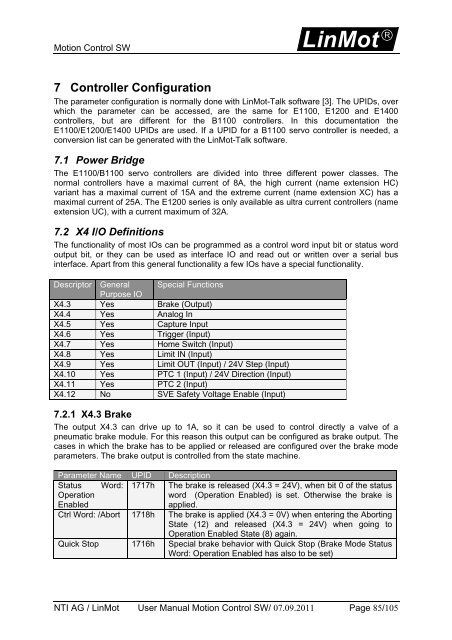
Descriptor General Special Functions<br />
Purpose IO<br />
X4.3 Yes Brake (Output)<br />
X4.4 Yes Analog In<br />
X4.5 Yes Capture Input<br />
X4.6 Yes Trigger (Input)<br />
X4.7 Yes Home Switch (Input)<br />
X4.8 Yes Limit IN (Input)<br />
X4.9 Yes Limit OUT (Input) / 24V Step (Input)<br />
X4.10 Yes PTC 1 (Input) / 24V Direction (Input)<br />
X4.11 Yes PTC 2 (Input)<br />
X4.12 No SVE Safety Voltage Enable (Input)<br />
7.2.1 X4.3 Brake<br />
The output X4.3 can drive up to 1A, so it can be used to control directly a valve of a<br />
pneumatic brake module. For this reason this output can be configured as brake output. The<br />
cases in which the brake has to be applied or released are configured over the brake mode<br />
parameters. The brake output is controlled from the state machine.<br />
Parameter Name UPID Description<br />
Status Word: 1717h The brake is released (X4.3 = 24V), when bit 0 of the status<br />
Operation<br />
Enabled<br />
word (Operation Enabled) is set. Otherwise the brake is<br />
applied.<br />
Ctrl Word: /Abort 1718h The brake is applied (X4.3 = 0V) when entering the Aborting<br />
State (12) and released (X4.3 = 24V) when going to<br />
Operation Enabled State (8) again.<br />
Quick Stop 1716h Special brake behavior with Quick Stop (Brake Mode Status<br />
Word: Operation Enabled has also to be set)<br />
NTI AG / <strong>LinMot</strong> User Manual Motion Control SW/ 07.09.2011 Page 85/105


