LinMot
LinMot
LinMot

Create successful ePaper yourself
Turn your PDF publications into a flip-book with our unique Google optimized e-Paper software.
Motion Control SW<br />
Documentation of the Motion Control SW<br />
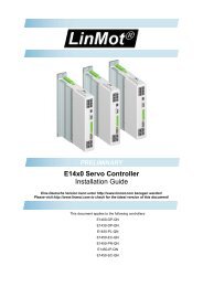
- E1200 Servo Controller Series<br />
- E1400 Servo Controller Series<br />
Motion Control SW SG5<br />
User Manual
© 2011 NTI AG<br />
This work is protected by copyright.<br />
Under the copyright laws, this publication may not be reproduced or transmitted in any form, electronic or mechanical, including<br />
photocopying,<br />
recording, microfilm, storing in an information retrieval system, not even for didactical use, or translating, in whole or in<br />
part, without the prior written consent of NTI AG.<br />
<strong>LinMot</strong>® is a registered trademark of NTI AG.<br />
Note<br />
The information in this documentation reflects the stage of development at the time of press and is therefore without obligation.<br />
NTI AG. reserves itself the right to make changes at any time and without notice to reflect further technical advance or product<br />
improvement.<br />
Document Version 4.3 / Whp, September 2011
Motion Control SW<br />
L i n M o t ®<br />
TABLE OF CONTENT<br />
SYSTEM OVERVIEW.......................................................................................................... 10<br />
1.1 REFERENCES ............................................................................................................. 10<br />
1.2 DEFINITIONS, ITEMS, SHORTCUTS............................................................................. 10<br />
1.3 DATA TYPES .............................................................................................................. 10<br />
2 MOTION CONTROL INTERFACES......................................................................... 11<br />
3 STATE MACHINE........................................................................................................ 12<br />
3.1 STATE 0: NOT READY TO SWITCH ON ...................................................................... 14<br />
3.2 STATE 1: SWITCH ON DISABLED ............................................................................... 14<br />
3.3 STATE 2: READY TO SWITCH ON .............................................................................. 14<br />
3.4 STATE 3: SETUP ERROR STATE.................................................................................. 14<br />
3.5 STATE 4: ERROR STATE ............................................................................................ 14<br />
3.6 STATE 5: HW TEST................................................................................................... 14<br />
3.7 STATE 6: READY TO OPERATE................................................................................... 14<br />
3.8 STATE 8: OPERATION ENABLED ................................................................................ 15<br />
3.9 STATE 9: HOMING ..................................................................................................... 15<br />
3.10 STATE 10: CLEARANCE CHECK ................................................................................. 15<br />
3.11 STATE 11: GOING TO INITIAL POSITION.................................................................... 15<br />
3.12 STATE 12: ABORTING................................................................................................ 16<br />
3.13 STATE 13: FREEZING................................................................................................. 16<br />
3.14 STATE 14: ERROR BEHAVIOUR QUICK STOP ............................................................. 16<br />
3.15 STATE 15: GOING TO POSITION................................................................................. 16<br />
3.16 STATE 16: JOGGING +................................................................................................ 16<br />
3.17 STATE 17: JOGGING - ................................................................................................ 16<br />
3.18 STATE 18: LINEARIZING............................................................................................ 16<br />
3.19 STATE 19: PHASE SEARCHING................................................................................... 16<br />
3.20 STATE 20: SPECIAL MODE ........................................................................................ 16<br />
3.21 BUILDING THE CONTROL WORD................................................................................ 17<br />
3.22 CONTROL WORD ....................................................................................................... 17<br />
3.23 STATUS WORD .......................................................................................................... 19<br />
3.24 WARN WORD ............................................................................................................ 20<br />
4 MOTION COMMAND INTERFACE......................................................................... 21<br />
4.1 MOTION COMMAND INTERFACE................................................................................ 21<br />
4.1.1 Command Header ............................................................................................ 21<br />
4.1.1.1 Master ID...................................................................................................... 21<br />
4.1.1.2 Sub ID .......................................................................................................... 21<br />
4.1.1.3 Command Count .......................................................................................... 21<br />
4.2 OVERVIEW MOTION COMMANDS .............................................................................. 22<br />
4.3 DETAILED MOTION COMMAND DESCRIPTION ........................................................... 28<br />
4.3.1 No Operation (000xh) ...................................................................................... 28<br />
4.3.2 Write Interface Control Word (001xh)............................................................. 28<br />
4.3.3 Write Live Parameter (002xh).......................................................................... 28<br />
4.3.4 Write X4 Intf Outputs with Mask (003xh) ........................................................ 28<br />
4.3.5 Select Position Controller Set (005xh)............................................................. 29<br />
4.3.6 Clear Event Evaluation (008xh)....................................................................... 29<br />
4.3.7 Master Homing (009xh) ................................................................................... 29<br />
NTI AG / <strong>LinMot</strong> User Manual Motion Control SW/ 07.09.2011 Page 3/105
L i n M o t ®<br />
Motion Control SW<br />
4.3.8 Reset (00Fxh) ................................................................................................... 29<br />
4.3.9 VAI Go To Pos (010xh) .................................................................................... 29<br />
4.3.10 VAI Increment Dem Pos (011xh) ..................................................................... 30<br />
4.3.11 VAI Increment Target Pos (012xh) .................................................................. 30<br />
4.3.12 VAI Go To Pos From Act Pos And Act Vel (013xh)......................................... 30<br />
4.3.13 VAI Go To Pos From Act Pos Starting With Dem Vel = 0 (014xh)................. 31<br />
4.3.14 VAI Increment Act Pos (015xh)........................................................................ 31<br />
4.3.15 VAI Increment Act Pos Starting With Dem Vel = 0 (016xh)............................ 31<br />
4.3.16 VAI Stop (017xh) .............................................................................................. 32<br />
4.3.17 VAI Go To Pos After Actual Command (018xh) .............................................. 32<br />
4.3.18 VAI Go To Analog Pos (019xh)........................................................................ 32<br />
4.3.19 VAI Go To Pos On Rising Trigger Event (01Axh) ........................................... 32<br />
4.3.20 VAI Increment Target Pos On Rising Trigger Event (01Bxh) ......................... 32<br />
4.3.21 VAI Go To Pos On Falling Trigger Event (01Cxh) ......................................... 33<br />
4.3.22 VAI Increment Target Pos On Falling Trigger Event (01Dxh) ....................... 33<br />
4.3.23 VAI Change Motion Parameters On Positive Position Transition (01Exh) .... 33<br />
4.3.24 VAI Change Motion Parameters On Negative Position Transition (01Fxh)... 33<br />
4.3.25 Predef VAI Go To Pos (020xh) ........................................................................ 34<br />
4.3.26 Predef VAI Increment Dem Pos (021xh).......................................................... 34<br />
4.3.27 Predef VAI Increment Target Pos (022xh)....................................................... 34<br />
4.3.28 Predef VAI Go To Pos From Act Pos and Act Vel (023xh).............................. 34<br />
4.3.29 Predef VAI Go To Pos From Act Pos Starting With Dem Vel = 0 (024xh) ..... 34<br />
4.3.30 Predef VAI Stop (027xh) .................................................................................. 34<br />
4.3.31 Predef VAI Go To Pos After Actual Command (028xh)................................... 35<br />
4.3.32 Predef VAI Go To Pos On Rising Trigger Event (02Axh)................................ 35<br />
4.3.33 Predef VAI Increment Target Pos On Rising Trigger Event (02Bxh).............. 35<br />
4.3.34 Predef VAI Go To Pos On Falling Trigger Event (02Cxh).............................. 35<br />
4.3.35 Predef VAI Go To Pos On Falling Trigger Event (02Dxh).............................. 35<br />
4.3.36 Predef VAI Infinite Motion Positive Direction (02Exh)................................... 35<br />
4.3.37 Predef VAI Infinite Motion Negative Direction (02Fxh) ................................. 35<br />
4.3.38 P Stream With Slave Generated Time Stamp (030xh)...................................... 36<br />
4.3.39 PV Stream With Slave Generated Time Stamp (031xh) ................................... 36<br />
4.3.40 P Stream With Slave Generated Time Stamp and Configured Period Time<br />
(032xh) 36<br />
4.3.41 PV Stream With Slave Generated Time Stamp Stamp and Configured Period<br />
Time (033xh) ....................................................................................................................36<br />
4.3.42 PVA Stream With Slave Generated Time Stamp (034xh)................................. 37<br />
4.3.43 PVA Stream With Slave Generated Time Stamp and Configured Period Time<br />
(035xh) 37<br />
4.3.44 Stop Streaming (03Fxh) ................................................................................... 38<br />
4.3.45 Time Curve With Default Parameters (040xh) ................................................ 38<br />
4.3.46 Time Curve With Default Parameters From Act Pos (041xh) ......................... 38<br />
4.3.47 Time Curve To Pos With Default Speed (042xh) ............................................. 38<br />
4.3.48 Time Curve To Pos With Adjustable Time (043xh).......................................... 38<br />
4.3.49 Time Curve With Adjustable Offset, Time Scale & Amplitude Scale (044xh).. 39<br />
4.3.50 Time Curve With Adjustable Offset, Time & Amplitude Scale (045xh) ........... 39<br />
4.3.51 Time Curve With Adjustable Offset, Time & Amplitude Scale On Rising<br />
Trigger Event (046xh) ...................................................................................................... 39<br />
4.3.52 Time Curve With Adjustable Offset, Time & Amplitude Scale On Falling<br />
Trigger Event (047xh) ...................................................................................................... 39<br />
Page 4/105 User Manual Motion Control SW / 07.09.2011 NTI AG / <strong>LinMot</strong>
Motion Control SW<br />
L i n M o t ®<br />
4.3.53 Time Curve To Pos With Default Speed On Rising Trigger Event (04Axh) .... 40<br />
4.3.54 Time Curve To Pos With Default Speed On Falling Trigger Event (04Cxh)... 40<br />
4.3.55 Time Curve To Pos With Adjustable Time On Rising Trigger Event (04Exh). 40<br />
4.3.56 Time Curve To Pos With Adjustable Time On Falling Trigger Event (04Fxh)40<br />
4.3.57 Modify Curve Start Address in RAM (050xh) .................................................. 40<br />
4.3.58 Modify Curve Info Block 16 Bit Value in RAM (051xh) .................................. 41<br />
4.3.59 Modify Curve Info Block 32 Bit Value in RAM (052xh) .................................. 41<br />
4.3.60 Modify Curve Data Block 32 Bit Value in RAM (054xh)................................. 42<br />
4.3.61 Modify Curve Data Block 64 Bit Value in RAM (055xh)................................. 42<br />
4.3.62 Modify Curve Data Block 96 Bit Value in RAM (056xh)................................. 43<br />
4.3.63 Setup Encoder Cam On Rising Trigger Event With Delay Counts (069xh)..... 43<br />
4.3.64 Setup Encoder Cam On Rising Trigger Event With Delay Counts, Target Pos<br />
and Length (06Axh).......................................................................................................... 43<br />
4.3.65 Setup Encoder Cam On Falling Trigger Event With Delay Counts (06Bxh)... 44<br />
4.3.66 Setup Encoder Cam On Falling Trigger Event With Delay Counts, Target Pos<br />
and Length (06Cxh).......................................................................................................... 44<br />
4.3.67 Setup Encoder Cam On Rising Trigger Event With Delay Counts, Amplitude<br />
scale and Length (06Dxh) ................................................................................................ 44<br />
4.3.68 Setup Encoder Cam On Falling Trigger Event With Delay Counts, Amplitude<br />
scale and Length (06Exh)................................................................................................. 45<br />
4.3.69 Start VAI Encoder Position Indexing (070xh).................................................. 45<br />
4.3.70 Start Predef VAI Encoder Position Indexing (071xh)...................................... 45<br />
4.3.71 Stop Position Indexing and VAI Go To Pos (07Exh) ....................................... 45<br />
4.3.72 Stop Position Indexing and VAI Go To Pos (07Fxh) ....................................... 46<br />
4.3.73 VAI 16 Bit Go To Pos (090xh) ......................................................................... 46<br />
4.3.74 VAI 16 Bit Increment Dem Pos (091xh)........................................................... 46<br />
4.3.75 VAI 16 Bit Increment Target Pos (092xh)........................................................ 46<br />
4.3.76 VAI 16 Bit Go To Pos From Act Pos And Act Vel (093xh) .............................. 47<br />
4.3.77 VAI 16 Bit Go To Pos From Act Pos Starting With Dem Vel = 0 (094xh) ...... 47<br />
4.3.78 VAI 16 Bit Increment Act Pos (095xh)............................................................. 47<br />
4.3.79 VAI 16 Bit Increment Act Pos Starting With Dem Vel = 0 (096xh)................. 47<br />
4.3.80 VAI 16 Bit Stop (097xh) ................................................................................... 47<br />
4.3.81 VAI 16 Bit Go To Pos After Actual Command (098xh).................................... 48<br />
4.3.82 VAI 16 Bit Go To Pos On Rising Trigger Event (09Axh)................................. 48<br />
4.3.83 VAI 16 Bit Increment Target Pos On Rising Trigger Event (09Bxh)............... 48<br />
4.3.84 VAI 16 Bit Go To Pos On Falling Trigger Event (09Cxh)............................... 48<br />
4.3.85 VAI 16 Bit Increment Target Pos On Falling Trigger Event (09Dxh)............. 49<br />
4.3.86 VAI 16 Bit Change Motion Parameters On Positive Position Transition<br />
(09Exh) 49<br />
4.3.87 VAI 16 Bit Change Motion Parameters On Negative Position Transition<br />
(09Fxh) 49<br />
4.3.88 Predef VAI 16 Bit Go To Pos (0A0xh) ............................................................. 49<br />
4.3.89 Predef VAI 16 Bit Increment Dem Pos (0A1xh)............................................... 50<br />
4.3.90 Predef VAI 16 Bit Increment Target Pos (0A2xh)............................................ 50<br />
4.3.91 Predef VAI 16 Bit Go To Pos From Act Pos And Act Vel (0A3xh).................. 50<br />
4.3.92 Predef VAI 16 Bit Go To Pos From Act Pos Starting With Dem Vel = 0<br />
(0A4xh) 50<br />
4.3.93 Predef VAI 16 Bit Stop (0A7xh) ....................................................................... 50<br />
4.3.94 Predef VAI 16 Bit Go To Pos After Actual Command (0A8xh) ....................... 50<br />
4.3.95 Predef VAI 16 Bit Go To Pos On Rising Trigger Event (0AAxh) .................... 51<br />
NTI AG / <strong>LinMot</strong> User Manual Motion Control SW/ 07.09.2011 Page 5/105
L i n M o t ®<br />
Motion Control SW<br />
4.3.96 Predef VAI 16 Bit Increment Target Pos On Rising Trigger Event (0ABxh)... 51<br />
4.3.97 Predef VAI 16 Bit Go To Pos On Falling Trigger Event (0ACxh)................... 51<br />
4.3.98 Predef VAI 16 Bit Increment Target Pos On Falling Trigger Event (0ADxh). 51<br />
4.3.99 VAI Predef Acc Go To Pos (0B0xh)................................................................. 51<br />
4.3.100 VAI Predef Acc Increment Dem Pos (0B1xh) ............................................. 51<br />
4.3.101 VAI Predef Acc Increment Target Pos (0B2xh) ........................................... 51<br />
4.3.102 VAI Predef Acc Go To Pos From Act Pos And Act Vel (0B3xh).................. 52<br />
4.3.103 VAI Predef Acc Go To Pos From Act Pos Starting With Dem Vel = 0<br />
(0B4xh) 52<br />
4.3.104 VAI Predef Acc Go To Pos After Actual Command (0B8xh) ....................... 52<br />
4.3.105 VAI Predef Acc Go To Pos On Rising Trigger Event (0BAxh) .................... 52<br />
4.3.106 VAI Predef Acc Increment Target Pos On Rising Trigger Event (0BBxh) .. 52<br />
4.3.107 VAI Predef Acc Go To Pos On Falling Trigger Event (0BCxh) .................. 53<br />
4.3.108 VAI Predef Acc Increment Target Pos On Falling Trigger Event (0BDxh) 53<br />
4.3.109 VAI Dec=Acc Go To Pos (0C0xh) ............................................................... 53<br />
4.3.110 VAI Dec=Acc Increment Dem Pos (0C1xh)................................................ 53<br />
4.3.111 VAI Dec=Acc Increment Target Pos (0C2xh).............................................. 53<br />
4.3.112 VAI Dec=Acc Go To Pos From Act Pos And Act Vel (0C3xh).................... 54<br />
4.3.113 VAI Dec=Acc Go To Pos From Act Pos Starting With Dem Vel = 0 (0C4xh)<br />
54<br />
4.3.114 VAI Dec=Acc Go To Pos With Max Curr (0C5xh)...................................... 54<br />
4.3.115 VAI Dec=Acc Go To Pos From Act Pos And Vel With Max Curr (0C6xh). 55<br />
4.3.116 VAI Dec=Acc Go To Pos From Act Pos And Vel = 0 With Max Curr<br />
(0C7xh) 55<br />
4.3.117 VAI Dec=Acc Go To Pos After Actual Command (0C8xh) ......................... 55<br />
4.3.118 VAI Dec=Acc Go To Pos On Rising Trigger Event (0CAxh) ...................... 56<br />
4.3.119 VAI Dec=Acc Increment Target Pos On Rising Trigger Event (0CBxh)..... 56<br />
4.3.120 VAI Dec=Acc Go To Pos On Falling Trigger Event (0CCxh)..................... 56<br />
4.3.121 VAI Dec=Acc Increment Target Pos On Falling Trigger Event (0CDxh)... 56<br />
4.3.122 VAI Increment Captured Pos (0D0xh)......................................................... 56<br />
4.3.123 VAI 16 Bit Dec=Acc Go To Pos (0D1xh) .................................................... 57<br />
4.3.124 VAI Go To Cmd Tab Var1 Pos (0D4xh) ...................................................... 57<br />
4.3.125 VAI Go To Cmd Tab Var2 Pos (0D5xh) ...................................................... 57<br />
4.3.126 VAI Go To Cmd Tab Var1 Pos From Act Pos And Act Vel (0D6xh) ........... 57<br />
4.3.127 VAI Go To Cmd Tab Var2 Pos From Act Pos And Act Vel (0D7xh) ........... 58<br />
4.3.128 VAI Start Trig Rise Config VAI Command (0DExh).................................... 58<br />
4.3.129 VAI Start Trig Rise Config VAI Command (0DFxh).................................... 58<br />
4.3.130 Sin VA Go To Pos (0E0xh)........................................................................... 58<br />
4.3.131 Sin VA Increment Demand Pos (0E1xh) ...................................................... 58<br />
4.3.132 Sin VA Go To Pos From Actual Pos (0E4xh)............................................... 59<br />
4.3.133 Sin VA Increment Actual Pos (0E6xh) ......................................................... 59<br />
4.3.134 Sin VA Go To Pos After Actual Command (0E8xh)..................................... 59<br />
4.3.135 Sin VA Go To Analog Pos (0E9xh) .............................................................. 60<br />
4.3.136 Sin VA Go To Pos On Rising Trigger Event (0EAxh).................................. 60<br />
4.3.137 Sin VA Increment Demand Pos On Rising Trigger Event (0EBxh) ............. 60<br />
4.3.138 Sin VA Go To Pos On Falling Trigger Event (0ECxh) ................................ 61<br />
4.3.139 Sin VA Increment Demand Pos On Falling Trigger Event (0EDxh) ........... 61<br />
4.3.140 Bestehorn VAJ Go To Pos (0F0xh).............................................................. 61<br />
4.3.141 Bestehorn VAJ Increment Demand Pos (0F1xh) ......................................... 62<br />
4.3.142 Bestehorn VAJ Go To Pos From Actual Pos (0F4xh).................................. 62<br />
Page 6/105 User Manual Motion Control SW / 07.09.2011 NTI AG / <strong>LinMot</strong>
Motion Control SW<br />
L i n M o t ®<br />
4.3.143 Bestehorn VAJ Increment Actual Pos (0F6xh) ............................................ 62<br />
4.3.144 Bestehorn VAJ Go To Pos After Actual Command (0F8xh) ........................ 63<br />
4.3.145 Bestehorn VAJ Go To Analog Pos (0F9xh) ................................................. 63<br />
4.3.146 Bestehorn VAJ Go To Pos On Rising Trigger Event (0FAxh) ..................... 63<br />
4.3.147 Bestehorn VAJ Increment Demand Pos On Rising Trigger Event (0FBxh) 64<br />
4.3.148 Bestehorn VAJ Go To Pos On Falling Trigger Event (0FCxh) ................... 64<br />
4.3.149 Bestehorn VAJ Increment Demand Pos On Falling Trigger Event (0FDxh)<br />
64<br />
4.3.150 Encoder Cam Enable (100xh)...................................................................... 65<br />
4.3.151 Encoder Cam Disable (101xh)..................................................................... 65<br />
4.3.152 Encoder Cam Go To Sync Pos (102xh)........................................................ 65<br />
4.3.153 Encoder Cam Set Value (104xh) .................................................................. 65<br />
4.3.154 Encoder Cam y Define Curve With Default Parameters (1y0xh) ................ 65<br />
4.3.155 Encoder Cam y Define Curve From Act Pos (1y1xh) .................................. 66<br />
4.3.156 Encoder Cam y Define Curve To Pos (1y2xh) ............................................. 66<br />
4.3.157 Encoder Cam y Define Curve From Pos To Pos In Counts (1y3xh)............ 66<br />
4.3.158 Encoder Cam y Define Curve To Pos In Counts (1y4xh) ............................ 66<br />
4.3.159 Encoder Cam y Define Curve With Amplitude Scale In Counts (1y5xh) ..... 67<br />
4.3.160 Encoder Cam y Enable (1y6xh) ................................................................... 67<br />
4.3.161 Encoder Cam y Disable (1y7xh) .................................................................. 67<br />
4.3.162 Encoder Cam y Change Amplitude Scale and Length (1y8xh) .................... 67<br />
4.3.163 Start Command Table Command (200xh).................................................... 67<br />
4.3.164 Start Command Table Command On Rising Trigger Event (201xh) ........... 67<br />
4.3.165 Start Command Table Command On Falling Trigger Event (202xh).......... 68<br />
4.3.166 Modify Command Table 16 bit Parameter in RAM (208xh)........................ 68<br />
4.3.167 Modify Command Table 32 bit Parameter in RAM (209xh)........................ 68<br />
4.3.168 Wait Time (210xh)........................................................................................ 68<br />
4.3.169 Wait Until Motion Finished (211xh) ............................................................ 68<br />
4.3.170 Wait Until In Target Position (212xh) ......................................................... 69<br />
4.3.171 Wait Until Rising Trigger Event (213xh) ..................................................... 69<br />
4.3.172 Wait Until Falling Trigger Event (214xh).................................................... 69<br />
4.3.173 Wait Until Demand Position Greater Than (220xh).................................... 69<br />
4.3.174 Wait Until Demand Position Less Than (221xh) ......................................... 69<br />
4.3.175 Wait Until Actual Position Greater Than (222xh)....................................... 69<br />
4.3.176 Wait Until Actual Position Less Than (223xh)............................................. 69<br />
4.3.177 Wait Until Difference Position Greater Than (224xh)................................. 70<br />
4.3.178 Wait Until Difference Position Less Than (225xh) ...................................... 70<br />
4.3.179 Wait Until Difference Position Unsigned Greater Than (226xh) ................ 70<br />
4.3.180 Wait Until Difference Position Unsigned Less Than (227xh)...................... 70<br />
4.3.181 Wait Until Demand Velocity Greater Than (228xh) .................................... 70<br />
4.3.182 Wait Until Demand Velocity Less Than (229xh).......................................... 70<br />
4.3.183 Wait Until Actual Velocity Greater Than (22Axh)....................................... 71<br />
4.3.184 Wait Until Actual Velocity Less Than (22Bxh) ............................................ 71<br />
4.3.185 Wait Until Current Greater Than (22Exh)................................................... 71<br />
4.3.186 Wait Until Current Less Than (22Fxh) ........................................................ 71<br />
4.3.187 Set Cmd Table Var 1 To (240xh).................................................................. 71<br />
4.3.188 Add To Cmd Table Var 1 (241xh) ................................................................ 71<br />
4.3.189 Set Cmd Table Var 2 To (242xh).................................................................. 71<br />
4.3.190 Add To Cmd Table Var 2 (243xh) ................................................................ 72<br />
4.3.191 Write Cmd Table Var 1 To UPID RAM value (248xh) ................................ 72<br />
NTI AG / <strong>LinMot</strong> User Manual Motion Control SW/ 07.09.2011 Page 7/105
L i n M o t ®<br />
Motion Control SW<br />
4.3.192 Write Cmd Table Var 2 To UPID RAM value (249xh) ................................ 72<br />
4.3.193 Write UPID RAM Value To Cmd Table Var 1 (24Cxh)............................... 72<br />
4.3.194 Write UPID RAM Value To Cmd Table Var 2 (24Dxh)............................... 72<br />
4.3.195 IF Cmd Table Var 1 Less Than (250xh)....................................................... 72<br />
4.3.196 IF Cmd Table Var 1 Greater Than (251xh) ................................................. 72<br />
4.3.197 IF Cmd Table Var 1 Less Than (252xh)....................................................... 72<br />
4.3.198 IF Cmd Table Var 1 Greater Than (253xh) ................................................. 73<br />
4.3.199 IF Demand Position Less Than (258xh) ...................................................... 73<br />
4.3.200 IF Demand Position Greater Than (259xh)................................................. 73<br />
4.3.201 IF Actual Position Less Than (25Axh) ......................................................... 73<br />
4.3.202 IF Actual Position Greater Than (25Bxh).................................................... 73<br />
4.3.203 IF Difference Position Less Than (25Cxh) .................................................. 73<br />
4.3.204 IF Difference Position Greater Than (25Dxh)............................................. 74<br />
4.3.205 IF Current Less Than (25Exh) ..................................................................... 74<br />
4.3.206 IF Current Greater Than (25Fxh)................................................................ 74<br />
4.3.207 IF Analog Val On X4.4 Less Than (260xh).................................................. 74<br />
4.3.208 IF Masked X4 Input Value Equal Than (262xh) .......................................... 74<br />
4.3.209 IF Masked X6 Input Value Equal Than (263xh) .......................................... 74<br />
4.3.210 IF Masked Status Word Equal Than (264xh)............................................... 75<br />
4.3.211 IF Masked Warn Word Equal Than (265xh)................................................ 75<br />
4.3.212 IF CAM Counts Less Than (266xh).............................................................. 75<br />
4.3.213 Encoder Winding Stop Adaptation Of Left/Right Position and Disturbance<br />
(304xh) 75<br />
4.3.214 Encoder Winding Restart Adaptation Of Left/Right Position and<br />
Disturbance (305xh)......................................................................................................... 75<br />
4.3.215 Encoder Curve Winding Start With Default Parameters (310xh)................ 75<br />
4.3.216 Encoder Curve Winding Start With Default Parameters At Revolutions<br />
(311xh) 76<br />
4.3.217 VAI Go To Pos With Higher Force Ctrl Limit (380xh)................................ 76<br />
4.3.218 VAI Go To Pos From Act Pos And Reset Force Control (381xh)................ 76<br />
4.3.219 Force Ctrl Change Target Force (382xh).................................................... 76<br />
4.3.220 VAI Go To Pos With Higher Force Ctrl Limit and Target Force (383xh)... 77<br />
4.3.221 VAI Go To Pos With Lower Force Ctrl Limit (384xh)................................. 77<br />
4.3.222 VAI Go To Pos With Lower Force Ctrl Limit and Target Force (385xh).... 77<br />
4.3.223 Current Command Mode (390xh) ................................................................ 77<br />
4.3.224 Change to Position Controlled Mode (39Fxh)............................................. 78<br />
5 SETPOINT GENERATION ......................................................................................... 79<br />
5.1 VA-INTERPOLATOR................................................................................................... 79<br />
5.1.1.1 Parameters and Output ................................................................................. 79<br />
5.2 SINE VA MOTION ..................................................................................................... 80<br />
5.2.1.1 Parameters and Output ................................................................................. 80<br />
5.3 BESTEHORN VAJ MOTION ........................................................................................ 81<br />
5.3.1.1 Parameters and Output ................................................................................. 81<br />
5.4 P(V)-STREAM ........................................................................................................... 82<br />
5.5 CAM MOTIONS .......................................................................................................... 83<br />
5.5.1 Triggered Cam Motions ................................................................................... 83<br />
5.5.2 Repeated Cam Motions with the Modulo CamMode ....................................... 83<br />
6 COMMAND TABLE ..................................................................................................... 84<br />
Page 8/105 User Manual Motion Control SW / 07.09.2011 NTI AG / <strong>LinMot</strong>
Motion Control SW<br />
L i n M o t ®<br />
7 CONTROLLER CONFIGURATION.......................................................................... 85<br />
7.1 POWER BRIDGE ......................................................................................................... 85<br />
7.2 X4 I/O DEFINITIONS ................................................................................................. 85<br />
7.2.1 X4.3 Brake........................................................................................................ 85<br />
7.2.1.1 X4.3 Brake Operation /Abort Behavior ....................................................... 86<br />
7.2.1.2 X4.3 Brake Operation Quick Stop Behavior................................................ 87<br />
7.2.2 X4.6 Trigger ..................................................................................................... 87<br />
7.2.2.1 Direct Trigger Mode..................................................................................... 87<br />
7.2.2.2 Inhibited Trigger Mode ................................................................................ 88<br />
7.2.2.3 Delayed Trigger Mode ................................................................................. 88<br />
7.2.2.4 Inhibited & Delayed Trigger Mode.............................................................. 89<br />
7.2.3 X4.8 and X4.9 Limit Switches........................................................................... 89<br />
7.2.4 X4.10 and X4.11 PTC 1 and PTC 2 ................................................................. 89<br />
7.2.5 X4.12 SVE (Safety Voltage Enable) ................................................................. 90<br />
7.3 MASTER ENCODER .................................................................................................... 90<br />
7.4 MONITORING............................................................................................................. 92<br />
7.4.1 Logic Supply Voltage ....................................................................................... 92<br />
7.4.2 Motor Supply Voltage....................................................................................... 92<br />
7.4.2.1 Phase Switch On Test................................................................................... 92<br />
7.4.3 Regeneration Resistor ...................................................................................... 93<br />
7.4.4 Temperature Monitoring.................................................................................. 94<br />
7.5 POSCTRLSTRUCTURE ................................................................................................ 95<br />
8 MOTOR CONFIGURATION ...................................................................................... 96<br />
8.1 GENERIC MOTOR TEMPERATURE CALCULATED........................................................ 96<br />
9 STATE MACHINE SETUP .......................................................................................... 97<br />
10 ERROR CODE LIST................................................................................................. 98<br />
11 CONTACT ADDRESSES ....................................................................................... 105<br />
NTI AG / <strong>LinMot</strong> User Manual Motion Control SW/ 07.09.2011 Page 9/105
L i n M o t ®<br />
Motion Control SW<br />
System Overview<br />
This user Manual describes the Motion Control SW functionality of the <strong>LinMot</strong> E1200 / E1400<br />
servo controllers.<br />
1.1 References<br />
Ref Title Source<br />
1 Installation_Guide_E1200.pdf www.linmot.com<br />
2 Installation_Guide_E1400.pdf www.linmot.com<br />
3 Usermanual_<strong>LinMot</strong>-Talk_4.pdf www.linmot.com<br />
The documentation is distributed with the <strong>LinMot</strong>-Talk configuration software or can be<br />
downloaded from the Internet from the download section of our homepage.<br />
1.2 Definitions, Items, Shortcuts<br />
Shortcut Meaning<br />
LM <strong>LinMot</strong> linear motor<br />
OS Operating system (Software)<br />
MC (SW) Motion Control (Software)<br />
Intf Interface (Software)<br />
Appl Application (Software)<br />
VAI VA-Interpolator (Max velocity limited acceleration position interpolator)<br />
Pos Position<br />
Vel Velocity<br />
Acc Acceleration<br />
Dec Deceleration<br />
UPID Unique Parameter ID (16 bit)<br />
1.3 Data types<br />
Type Range/Format Num of bytes<br />
Bool Boolean, False/True 1/8<br />
Byte 0..255 1<br />
Char ASCII 1<br />
String Array of char last char = 00h X<br />
SInt16 -32768..32767 2<br />
UInt16 0..65535 2<br />
SInt32 -2147483648..2147483647 4<br />
UInt32 0..4294967295 4<br />
Float 4<br />
Page 10/105 User Manual Motion Control SW / 07.09.2011 NTI AG / <strong>LinMot</strong>
Motion Control SW<br />
L i n M o t ®<br />
2 Motion Control Interfaces<br />
For controlling the behavior of the motion control SW, two different Interfaces are available.<br />
For controlling the main state machine, a bit coded control word can be used. For<br />
controlling the motion functionality a memory mapped motion command interface can be<br />
used. These two instances are mapped via an interface SW to an upper control system<br />
(PLC, IPC, PC, ..). The interfacing is done with digital I/Os or a serial link like Profibus DP,<br />
CAN bus (CANopen), RS485, RS422 or RS232 (LinRS protocol).Ethernet (POWERLINK,<br />
EtherCAT, Ethernet/IP).<br />
With <strong>LinMot</strong>-Talk the control over the control word can be taken bit by bit, for testing and<br />
debugging. Unused control word bits can be forced by parameter value.<br />
Also the control of the motion command interpreter can be switched to the control panel of<br />
the <strong>LinMot</strong>-Talk software for testing.<br />
All this can be done while the system is running, so be careful using this features on a<br />
running machine!<br />
Realtime Machine Control<br />
Monitoring, Testing, Simulating<br />
PLC<br />
with serial bus<br />
<strong>LinMot</strong>-Talk1100<br />
Control Panel<br />
Interface Control<br />
Word<br />
Motion<br />
Command<br />
Registers<br />
Control Word<br />
Parameter Force Values<br />
Motion<br />
Command<br />
Registers<br />
Control Word Intf<br />
Copy Mask<br />
Control Word<br />
Parameter Force Mask<br />
Motion Command<br />
Interface Selector<br />
Event<br />
Handler<br />
Control Word<br />
Status Word<br />
Command<br />
Registers<br />
Response<br />
Registers<br />
State Machine Control<br />
Motion Command<br />
Interpreter<br />
Axle Control<br />
NTI AG / <strong>LinMot</strong> User Manual Motion Control SW/ 07.09.2011 Page 11/105
L i n M o t ®<br />
Motion Control SW<br />
3 State Machine<br />
The main behavior of the axles is controlled with the control word, it is shown in the following<br />
state diagram.<br />
Not Ready to<br />
Switch On (0)<br />
Bit 0=0<br />
Switch On<br />
Disabled (1)<br />
Control Word<br />
xxxx xxxx xxxx x110<br />
Ready to<br />
Switch On (2)<br />
Bit 0=1<br />
Bit 7<br />
Error (4)<br />
Setup Error (3)<br />
HW Tests (5)<br />
I=0<br />
Bit 0=0<br />
Switch Off<br />
Ready to<br />
Operate (6)<br />
Bit 3=1<br />
Operation<br />
Enabled (8)<br />
Power On<br />
Bit 1=0<br />
Disable<br />
Voltage<br />
Error Behavior<br />
Quick Stop (14)<br />
QuickStop<br />
Bit 2=0<br />
Homing (9)<br />
Clearance<br />
Checking (10)<br />
Going To Initial<br />
Position (11)<br />
Aborting (12)<br />
Freezing (13)<br />
Jogging + (16)<br />
Jogging - (17)<br />
Going To Position (15)<br />
Linearizing (18)<br />
Phase Searching (19)<br />
Special Mode (20)<br />
Page 12/105 User Manual Motion Control SW / 07.09.2011 NTI AG / <strong>LinMot</strong>
Motion Control SW<br />
L i n M o t ®<br />
The state machine can be followed in the PLCs with fieldbus using the the StateVar. This<br />
response word can be configured for any supported fieldbus.<br />
State Var<br />
Main State<br />
Sub State<br />
15 14 13 12 11 10 9 8 7 6 5 4 3 2 1 0<br />
The State Var is divided into two sections: the Main State section (high byte) contains directly<br />
the number of the state machine, the content of the Sub State (low byte) is state depending.<br />
State Var<br />
Main State<br />
Sub State<br />
00: Not Ready To Switch On 0<br />
01: Switch On Disabled 0<br />
02: Ready To Switch On 0<br />
03: Setup Error Error Code which will be logged<br />
04: Error Logged Error Code<br />
05: HW Tests 0 (Not yet defined)<br />
06: Ready To Operate 0 (Not yet defined)<br />
07: -<br />
08: Operation Enabled Bits 0..3: Motion Command Count<br />
Bit 4: Event Handler Active<br />
Bit 5: Motion Active<br />
Bit 6: In Target Position<br />
Bit 7: Homed<br />
09: Homing 0Fh: Homing Finished<br />
10: Clearance Check 0Fh: Clearance Check Finished<br />
11: Going To Initial Position 0Fh: Going To Initial Position Finished<br />
12: Aborting Not yet defined<br />
13: Freezing Not yet defined<br />
14: Quick Stop (Error Behaviour) Not yet defined<br />
15: Going To Position 0Fh: Going To Position Finished<br />
16: Jogging + 01h: Moving positive<br />
0Fh: Jogging +Finished<br />
17: Jogging - 01h: Moving negative<br />
0Fh: Jogging -Finished<br />
18: Linearizing Not yet defined<br />
19: Phase Search Not yet defined<br />
20: Special Mode Not yet defined<br />
NTI AG / <strong>LinMot</strong> User Manual Motion Control SW/ 07.09.2011 Page 13/105
L i n M o t ®<br />
Motion Control SW<br />
3.1 State 0: Not Ready To Switch On<br />
In this state the release of control word bit 0 switch on is awaited. As soon as this bit is<br />
cleared a change to state 1 is performed. This behavior avoids self starting if all necessary<br />
bits for a start are set correctly in the control word.<br />
3.2 State 1: Switch On Disabled<br />
The state machine rests in this state as long as the bits 1 or 2 of the control word are<br />
cleared.<br />
3.3 State 2: Ready To Switch On<br />
The state machine rests in this state as long as the bit 0 is cleared.<br />
3.4 State 3: Setup Error State<br />
The state machine rests in this state as long the bits 0 is cleared.<br />
3.5 State 4: Error State<br />
The error state can be acknowledged with a rising edge of the control word bit 7 ‘Error<br />
Acknowledge’. If the error is fatal, bit 12 ‘Fatal Error’ in the status word is set, no error<br />
acknowledgment is possible.<br />
In the case of a fatal error, the error has to be checked, and the problem has to be solved<br />
before a reset or power cycle is done for resetting the error.<br />
3.6 State 5: HW Test<br />
The HW Test state is an intermediate state before turning on the power stage of the servo<br />
controller. If everything seems to be ok the servo changes to state 6 without any user action.<br />
The test takes about 300ms.<br />
3.7 State 6: Ready to Operate<br />
In this state the motor is either position controlled or with demand current = 0 and under<br />
voltage, but no motion commands are accepted. The mode is configurable with UPID 6300h.<br />
Sending motion commands in this state will generate the error ‘Motion command sent in<br />
wrong state’ and a state change to the error state will be performed.<br />
Clearing the control word bit 3 ‘Enable Operation’ in state 8 or higher will stop immediately<br />
the set point generation and a state transition to 6 is performed. Clearing the bit while a<br />
motion is in execution a following error might be generated.<br />
Page 14/105 User Manual Motion Control SW / 07.09.2011 NTI AG / <strong>LinMot</strong>
Motion Control SW<br />
L i n M o t ®<br />
3.8 State 8: Operation Enabled<br />
This is the state of the normal operation in which the motion commands are executed. It is<br />
strongly recommended to use the State Var for the motion command synchronization with<br />
any fieldbus system.<br />
Main State = 8<br />
State Var<br />
H<br />
o<br />
m<br />
e<br />
d<br />
NTI AG / <strong>LinMot</strong> User Manual Motion Control SW/ 07.09.2011 Page 15/105<br />
I<br />
n<br />
T<br />
a<br />
r<br />
g<br />
e<br />
t<br />
P<br />
o<br />
s<br />
it<br />
i<br />
o<br />
n<br />
M<br />
o<br />
ti<br />
o<br />
n<br />
A<br />
c<br />
ti<br />
v<br />
e<br />
E<br />
v<br />
e<br />
n<br />
t<br />
H<br />
a<br />
n<br />
d<br />
l<br />
e<br />
r<br />
Motion Command<br />
Count<br />
15 14 13 12 11 10 9 8 7 6 5 4 3 2 1 0<br />
In the high byte stands the number of the main state = 8. In the low byte stands in the lowest<br />
4 bits the actual interpreted ‘Motion Command Count’, bit 4 indicates if the event handler is<br />
active, in bit 5 stands the status word bit ‘Motion Active’, in bit 6 the status word bit ‘In Target<br />
Position’ and in bit 7 the status word bit ‘Homed’. Because the ‘Motion Command Count’<br />
echo and this status word bits are located in the same byte no data consistency problem is<br />
possible with any fieldbus.<br />
A new motion command can be setup when the Motion Command Count has changed to the<br />
last sent and the ‘Motion Active’ bit is 0 or the ‘In Target Position’ bit is 1 if an exact<br />
positioning is required.<br />
3.9 State 9: Homing<br />
The homing state is used to define the position of the system according a mechanical<br />
reference, a home switch or an index.<br />
For <strong>LinMot</strong> motors the slider home position at this home position is taken to compensate<br />
edge effects.<br />
In the home sequence a position check of two positions and the motion to an initial position<br />
can be added.<br />
Hint: If a mechanical stop homing mode is chosen, the initial position should be a little apart<br />
from this mechanical stop to avoid overheating of the motor.<br />
3.10 State 10: Clearance Check<br />
Setting the Clearance Check bit in the Control Word, two positions are moved to, to check if<br />
the whole motion range is free. Normally this action is added to the homing sequence to<br />
ensure that the homing was done correctly.<br />
3.11 State 11: Going To Initial Position<br />
Setting the Go To Initial Position bit in the control word, the servo moves to the initial<br />
position, normally used to move away from the mechanical stop after homing, to protect the
L i n M o t ®<br />
Motion Control SW<br />
motor from overheating at the mechanical stop. After an error it is also recommended to<br />
move to a defined position again.<br />
3.12 State 12: Aborting<br />
Clearing the /Abort bit in the control word initiates a quick stop. After the motion has stopped<br />
the servo rests position controlled. Setting the bit again the servo controller rests in position<br />
until a new motion command is executed.<br />
3.13 State 13: Freezing<br />
Clearing the /Freeze bit in the control word initiates a quick stop. After the motion is stopped<br />
the servo rests position controlled. Setting the bit again the servo controller will finish the<br />
frozen motion (e.g. if it was a VAI command). Curve motion can be frozen but not restarted<br />
by releasing this bit, setting the bit again the motor moves at the target position of the last<br />
VAI command, if never used a VAI command it will go to the initial position.<br />
3.14 State 14: Error Behaviour Quick Stop<br />
Most of the errors, which can occur during an active motion, cause a quick stop behavior to<br />
stop the motion. After the quick stop is finished the motor is no longer position controlled.<br />
3.15 State 15: Going To Position<br />
Setting the Go To Position bit in the control word, the serveo moves to the defined position,<br />
recommendable for example, after an error, to move to a defined position again.<br />
3.16 State 16: Jogging +<br />
Setting the Jog Move + bit in the control word, the servo moves either a defined position<br />
increment or to the maximal position with a limited speed. Releasing the bit will stop the<br />
motion.<br />
3.17 State 17: Jogging -<br />
Setting the Jog Move - bit in the control word, the servo moves either a defined position<br />
decrement or to the minimal position with a limited speed. Releasing the bit will stop the<br />
motion<br />
3.18 State 18: Linearizing<br />
The linearizing state is used to correct position feedback parameters, to improve the linearity<br />
of the position feedback.<br />
3.19 State 19: Phase Searching<br />
The phase search is only defined for three phase EC motors with hall switches and ABZsensors<br />
to find the commutation offset for to the sensor. It cannot be guaranteed that this<br />
feature will work for all kinds of EC motors. The found offset can be found in the variable<br />
section Calculated Commutation Offset (UPID: 1C1Bh), and has to be set manually to he<br />
parameter Phase Angle (UPID 11F2h).<br />
3.20 State 20: Special Mode<br />
The Special Mode is available only on the B1100 servo controllers. In this state the current<br />
command mode over the analog input is available. For using this mode see the [4].<br />
Page 16/105 User Manual Motion Control SW / 07.09.2011 NTI AG / <strong>LinMot</strong>
Motion Control SW<br />
L i n M o t ®<br />
3.21 Building the Control Word<br />
The Control Word can be accessed bit by bit from different sources with different priorities.<br />
The highest priorities have the bits that are forced by parameters. The second highest priority<br />
has the control panel of the <strong>LinMot</strong>-Talk software, if logged in with the SW. The next lower<br />
priorities have the bits that are defined on the X4 IOs as control word input bits. The lowest<br />
priority have bits which are set over the interface (normally a serial fieldbus connection), so in<br />
the Ctrl Word Interface Copy mask all bits can be selected, without causing any problems,<br />
but bits which should not be accessed through the interface can be masked out.<br />
3.22 Control Word<br />
With the Control Word (16Bit) the main state machine of the servo controller can be<br />
accessed. Following table shows the meaning of each bit:<br />
Bit<br />
Name Val Meaning Remark<br />
0<br />
Switch On<br />
0<br />
1<br />
OFF1<br />
ON<br />
A-Stop, -> Current = 0, power switches<br />
disabled<br />
State change from switch on disabled to<br />
ready to switch on<br />
1<br />
Voltage Enable<br />
0 OFF2 Power switches disabled without<br />
microcontroller action<br />
2<br />
/Quick Stop<br />
3<br />
Enable Operation<br />
4<br />
/Abort<br />
5<br />
/Freeze<br />
1 Operation<br />
0 OFF3 Quick Stop -> Current = 0 -> H-Bridges<br />
disabled<br />
1 Operation<br />
0 Operation disabled Position controller active Motion Commands<br />
disabled<br />
1 Operation enable Position controller active Motion Commands<br />
enabled<br />
0 Abort Quick Stop position control rests active,<br />
motion command is cleared.<br />
1 Operation<br />
0 Freeze motion Quick Stop position control rests active,<br />
Target position not cleared, curves motions<br />
are aborted<br />
1 Operation Rising edge will reactivate motion command<br />
6<br />
0<br />
Go To Position 1 Go To Position Go to fixed parameterized Position. Wait for<br />
release of signal.<br />
7<br />
0<br />
Error Acknowledge 1 Error Acknowledge Rising edge of signal acknowledges error<br />
8<br />
0<br />
Jog Move + 1 Jog Move +<br />
9<br />
0<br />
Jog Move - 1 Jog Move -<br />
10<br />
0<br />
Special Mode 1 Special Mode Special Mode<br />
11<br />
0 Stop Homing<br />
Home 1 Homing At startup bit 11 Status word is cleared, until<br />
procedure is finished.<br />
12<br />
0 Stop Clearance Check<br />
Clearance Check 1 Clearance Check Enable Clearance Check Movements<br />
13<br />
0<br />
Go To Initial Position 1 Go To initial Position Rising edge will start go to initial position<br />
14 0<br />
NTI AG / <strong>LinMot</strong> User Manual Motion Control SW/ 07.09.2011 Page 17/105
L i n M o t ®<br />
Motion Control SW<br />
Reserved 1 Reserved<br />
15<br />
0 Stop Phase Search<br />
Phase Search 1 Phase Search Enable Phase Search Movements<br />
Page 18/105 User Manual Motion Control SW / 07.09.2011 NTI AG / <strong>LinMot</strong>
Motion Control SW<br />
L i n M o t ®<br />
3.23 Status Word<br />
Following table shows the meaning of the single bits:¬<br />
Bit<br />
Name Val Meaning Remark<br />
0<br />
0 State Nr < 8<br />
Operation Enabled 1 Operation Enabled State Nr 8 or higher (copied to Controller EN LED )<br />
1<br />
0 Switch On Disabled<br />
Switch On Active 1 Switch On Enabled<br />
2<br />
0 Operation Disabled<br />
Enable Operation 1 Operation<br />
Control Word Bit 0<br />
Control Word Bit 3<br />
3<br />
0 No Error<br />
Error 1 Error Acknowledge with Control word Bit 7 (Reset Error)<br />
4<br />
0 Power Bridge Off<br />
Voltage Enable 1 Operation<br />
5<br />
0 Active<br />
/Quick Stop 1 Operation<br />
Control Word Bit 1<br />
Control Word Bit 2<br />
6<br />
0 Not Locked<br />
Switch On Locked 1 Switch On Locked Release with 0 of Control word bit 0 (Switch On)<br />
7<br />
0 Warning not active No bit is set in the Warn Word<br />
Warning 1 Warning active One or more bits in the Warn Word are set<br />
8<br />
0 Event Handler Inactive Event Handler cleared or disabled<br />
Event Handler Active 1 Event Handler Active Event Handler setup<br />
9<br />
0 Normal Operation<br />
Special Motion Active 1 Special Command runs Special motion commands (Homing, ..) runs<br />
10<br />
0 Not In Pos Motion active or actual position out of window<br />
In Target Position 1 In Pos Actual position after motion in window<br />
11<br />
0 Motor not homed Incremental sensor not homed (referenced)<br />
Homed 1 Motor homed Position sensor system valid<br />
12<br />
0<br />
Fatal Error 1 Fatal Error A fatal error can not be acknowledged!<br />
13<br />
0 No Motion Setpoint generation inactive<br />
Motion Active 1 Motion active Setpoint generation (VAI, curve) active<br />
14<br />
0 Not In Range 1 Defined UPID is not in Range 1<br />
Range Indicator 1 1 In Range1 Defined UPID is in Range 1<br />
15<br />
0 Not In Range 2 Defined UPID is not in Range 2<br />
Range Indicator 2 1 In Range2 Defined UPID is in Range 2<br />
NTI AG / <strong>LinMot</strong> User Manual Motion Control SW/ 07.09.2011 Page 19/105
L i n M o t ®<br />
Motion Control SW<br />
3.24 Warn Word<br />
Following table shows the meaning of the single bits of the Warn Word:<br />
Bit<br />
Name Val Meaning<br />
0<br />
0 Normal Operation<br />
Motor Hot Sensor 1 Motor Temperature Sensor On<br />
1<br />
0 Normal Operation<br />
Motor Short Time Overload I^2t 1 Calculated Motor Temperature Reached Warn Limit<br />
2<br />
0 Normal Operation<br />
Motor Supply Voltage Low 1 Motor Supply Voltage Reached Low Warn Limit<br />
3<br />
0 Normal Operation<br />
Motor Supply Voltage High 1 Motor Supply Voltage Reached High Warn Limit<br />
4<br />
0 Normal Operation<br />
Position Lag Always 1 Position Error during Moving Reached Warn Limit<br />
5<br />
0<br />
Reserved 1<br />
6<br />
0 Normal Operation<br />
Controller Hot 1 Temperature on Servo Controller High<br />
7<br />
0 Normal Operation<br />
Motor Not Homed 1 Warning Motor Not Homed Yet<br />
8<br />
0 Normal Operation<br />
PTC Sensor 1 Hot 1 PTC Temperature Sensor 1 On<br />
9<br />
0 Normal Operation<br />
Reserved PTC 2 1 PTC Temperature Sensor 2 On<br />
10<br />
0 Normal Operation<br />
RR Hot Calculated 1 Regenerative Resistor Temperature Hot Calculated<br />
11<br />
0<br />
Reserved 1<br />
12<br />
0<br />
Reserved 1<br />
13<br />
0<br />
Reserved 1<br />
14<br />
0 Normal Operation<br />
Interface Warn Flag 1 Warn Flag Of Interface SW layer<br />
15<br />
0 Normal Operation<br />
Application Warn Flag 1 Warn Flag Of Application SW layer<br />
Normally the warn word bits are used to react in conditions before the controller goes into the<br />
error state. E.g. a typical reaction on the warning ‘Motor Temperature Sensor’ would be a stop<br />
of the machine, before the controller goes into the error state and the motor goes out of<br />
control to avoid crashes.<br />
Page 20/105 User Manual Motion Control SW / 07.09.2011 NTI AG / <strong>LinMot</strong>
Motion Control SW<br />
L i n M o t ®<br />
4 Motion Command Interface<br />
4.1 Motion Command Interface<br />
The motion command interface consists of one word that contains the command ID, and up<br />
to 16 command parameter words. Example: ‘VA-Interpolator 16 bit Go To Absolute Position’<br />
Word Description Example of command<br />
1. Command Header with ID Go To Absolute Position Immediate<br />
2. 1. Command Parameter Position<br />
3. 2. Command Parameter Maximal Speed<br />
4. 3. Command Parameter Acceleration<br />
5. 4. Command Parameter Deceleration<br />
6.-16. 5. - Command Parameter Not used<br />
4.1.1 Command Header<br />
Master ID Sub ID Command Count<br />
15 14 13 12 11 10 9 8 7 6 5 4 3 2 1 0<br />
The header of the Motion command is split into three parts:<br />
• Master ID<br />
• Sub ID<br />
• Command Count<br />
4.1.1.1 Master ID<br />
The master ID specifies the command group.<br />
4.1.1.2 Sub ID<br />
The sub ID is used to identify different commands from the same command group.<br />
4.1.1.3 Command Count<br />
A new command will only be executed, if the value of the command count has changed. In<br />
the easiest way bit 0 can be toggled.<br />
NTI AG / <strong>LinMot</strong> User Manual Motion Control SW/ 07.09.2011 Page 21/105
L i n M o t ®<br />
Motion Control SW<br />
4.2 Overview Motion Commands<br />
Master<br />
ID<br />
00h<br />
01h<br />
02h<br />
03h<br />
Sub<br />
ID<br />
E<br />
1<br />
2<br />
0<br />
0<br />
E<br />
4<br />
2<br />
0<br />
0<br />
Description<br />
0h X X No Operation<br />
1h X X Write Interface Control Word<br />
2h X X Write Live Parameter<br />
3h X X Write X4/X14 Intf Outputs with Mask<br />
5h X X Select Position Controller Set<br />
8h X X Clear Event Evaluation<br />
9h X X Master Homing<br />
Fh X X Reset<br />
0h X X VAI Go To Pos<br />
1h X X VAI Increment Dem Pos<br />
2h X X VAI Increment Target Pos<br />
3h X X VAI Go To Pos From Act Pos And Act Vel<br />
4h X X VAI Go To Pos From Act Pos Starting With Dem Vel = 0<br />
5h X X VAI Increment Act Pos<br />
6h X X VAI Increment Act Pos Starting with Dem Vel = 0<br />
7h X X VAI Stop<br />
8h X X VAI Go To Pos After Actual Command<br />
9h X X VAI Go To Analog Pos<br />
Ah X X VAI Go To Pos On Rising Trigger Event<br />
Bh X X VAI Increment Target Pos On Rising Trigger Event<br />
Ch X X VAI Go To Pos On Falling Trigger Event<br />
Dh X X VAI Increment Target Pos On Falling Trigger Event<br />
Eh X X VAI Change Motion Parameters On Positive Position Transition<br />
Fh X X VAI Change Motion Parameters On Negative Position Transition<br />
0h X X Predef VAI Go To Pos<br />
1h X X Predef VAI Increment Dem Pos<br />
2h X X Predef VAI Increment Target Pos<br />
3h X X Predef VAI Go To Pos From Act Pos And Act Vel<br />
4h X X Predef VAI Go To Pos From Act Pos Starting With Dem Vel = 0<br />
7h X X Predef VAI Stop With Quick Stop Deceleration<br />
8h X X Predef VAI Go To Pos After Actual Command<br />
Ah X X Predef VAI Go To Pos On Rising Trigger Event<br />
Bh X X Predef VAI Increment Target Pos On Rising Trigger Event<br />
Ch X X Predef VAI Go To Pos On Falling Trigger Event<br />
Dh X X Predef VAI Increment Target Pos On Falling Trigger Event<br />
Eh X X Predef VAI Infinite Motion Positive Direction<br />
Fh X X Predef VAI Infinite Motion Negative Direction<br />
0h X X P Stream With Slave Generated Time Stamp<br />
1h X X PV Stream With Slave Generated Time Stamp<br />
2h X X P Stream With Slave Generated Time Stamp and Configured<br />
Period Time<br />
3h X X PV Stream With Slave Generated Time Stamp and Configured<br />
Period Time<br />
4h X X PVA Stream With Slave Generated Time Stamp<br />
Page 22/105 User Manual Motion Control SW / 07.09.2011 NTI AG / <strong>LinMot</strong>
Motion Control SW<br />
L i n M o t ®<br />
04h<br />
05h<br />
06h<br />
07h<br />
09h<br />
5h X X PV Stream With Slave Generated Time Stamp and Configured<br />
Period Time<br />
Fh X X Stop Streaming<br />
0h X X Time Curve With Default Parameters<br />
1h X X Time Curve With Default Parameters From Act Pos<br />
2h X X Time Curve To Pos With Default Speed<br />
3h X X Time Curve To Pos With Adjustable Time<br />
4h X X Time Curve With Adjustable Offset, Time Scale & Amplitude Scale<br />
5h X X Time Curve With Adjustable Offset, Time & Amplitude Scale<br />
6h X X Time Curve With Adjustable Offset, Time & Amplitude Scale On<br />
Rising Trigger Event<br />
7h X X Time Curve With Adjustable Offset, Time & Amplitude Scale On<br />
Falling Trigger Event<br />
Ah X X Time Curve To Pos With Default Speed On Rising Trigger Event<br />
Ch X X Time Curve To Pos With Default Speed On Falling Trigger Event<br />
Eh X X Time Curve To Pos With Adjustable Time On Rising Trigger Event<br />
Fh X X Time Curve To Pos With Adjustable Time On Falling Trigger Event<br />
0h X X Modify Curve Start Address in RAM<br />
1h X X Modify Curve Info Block 16 Bit Value in RAM<br />
2h X X Modify Curve Info block 32 Bit Value in RAM<br />
4h X X Modify Curve Data Block 32 Bit in RAM<br />
5h X X Modify Curve Data Block 64 Bit in RAM<br />
6h X X Modify Curve Data Block 96 Bit in RAM<br />
4h X X Setup Encoder CAM from Actual Counts With Delay Counts<br />
9h X X Setup Encoder CAM On Rise Trigger Event With Delay Counts<br />
Ah X X Setup Encoder CANM On Rise Trigger Event With Delay Counts,<br />
Target Pos and Length<br />
Bh X X Setup Encoder CAM On Fall Trigger Event With Delay Counts<br />
Ch X X Setup Encoder CAM On Fall Trigger Event With Delay Counts,<br />
Target Pos and Length<br />
Dh X X Setup Encoder CAM On Rise Trigger Event With Delay Counts<br />
Amplitude scale and length<br />
Eh X X Setup Encoder CAM On Fall Trigger Event With Delay Counts<br />
Amplitude scale and length<br />
0h X X Start VAI Encoder Position Indexing<br />
1h X X Start Predef VAI Encoder Position Indexing<br />
Eh X X Stop Position Indexing And VAI Go To Pos<br />
Fh X X Stop Position Indexing And Predefined VAI Go To Pos<br />
0h X X VAI 16 Bit Go To Pos<br />
1h X X VAI 16 Bit Increment Dem Pos<br />
2h X X VAI 16 Bit Increment Target Pos<br />
3h X X VAI 16 Bit Go To Pos From Act Pos And Act Vel<br />
4h X X VAI 16 Bit Go To Pos From Act Pos Starting With Dem Vel = 0<br />
5h X X VAI 16Bit Increment Act Pos<br />
6h X X VAI Increment Act Pos Starting with Dem Vel = 0<br />
7h X X VAI 16 Bit Stop<br />
8h X X VAI 16 Bit Go To Pos After Actual Command<br />
Ah X X VAI 16 Bit Go To Pos On Rising Trigger Event<br />
Bh X X VAI 16 Bit Increment Target Pos On Rising Trigger Event<br />
Ch X X VAI 16 Bit Go To Pos On Falling Trigger Event<br />
Dh X X VAI 16 Bit Increment Target Pos On Falling Trigger Event<br />
NTI AG / <strong>LinMot</strong> User Manual Motion Control SW/ 07.09.2011 Page 23/105
L i n M o t ®<br />
Motion Control SW<br />
Eh X X VAI 16 Bit Change Motion Parameters On Positive Position<br />
Transition<br />
Fh X X VAI 16 Bit Change Motion Parameters On Negative Position<br />
Transition<br />
0Ah 0h X X Predef VAI 16 Bit Go To Pos<br />
1h X X Predef VAI 16 Bit Increment Dem Pos<br />
2h X X Predef VAI 16 Bit Increment Target Pos<br />
3h X X Predef VAI 16 Bit Go To Pos From Act Pos And Act Vel<br />
4h X X Predef VAI 16 Bit Go To Pos From Act Pos Starting With Dem Vel<br />
= 0<br />
7h X X Predef VAI 16 Bit Stop With Quick Stop Deceleration<br />
8h X X Predef VAI 16 Bit Go To Pos After Actual Command<br />
Ah X X Predef VAI 16 Bit Go To Pos On Rising Trigger Event<br />
Bh X X Predef VAI 16 Bit Increment Target Pos On Rising Trigger Event<br />
Ch X X Predef VAI 16 Bit Go To Pos On Falling Trigger Event<br />
Dh X X Predef VAI 16 Bit Increment Target Pos On Falling Trigger Event<br />
0Bh 0h X X VAI Predef Acc Go To Pos<br />
1h X X VAI Predef Acc Increment Dem Pos<br />
2h X X VAI Predef Acc Increment Target Pos<br />
3h X X VAI Predef Acc Go To Pos From Act Pos And Act Vel<br />
4h X X VAI Predef Acc Go To Pos From Act Pos Starting With Dem Vel =<br />
0<br />
8h X X VAI Predef Acc Go To Pos After Actual Command<br />
Ah X X VAI Predef Acc Go To Pos On Rising Trigger Event<br />
Bh X X VAI Predef Acc Increment Target Pos On Rising Trigger Event<br />
Ch X X VAI Predef Acc Go To Pos On Falling Trigger Event<br />
Dh X X VAI Predef Acc Increment Target Pos On Falling Trigger Event<br />
0Ch 0h X X VAI Dec=Acc Go To Pos<br />
1h X X VAI Dec=Acc Increment Dem Pos<br />
2h X X VAI Dec=Acc Increment Target Pos<br />
3h X X VAI Dec=Acc Go To Pos From Act Pos And Act Vel<br />
4h X X VAI Dec=Acc Go To Pos From Act Pos Starting With Dem Vel = 0<br />
5h X X VAI Dec=Acc Go To Pos With Max Curr<br />
6h X X VAI Dec=Acc Go To Pos From Act Pos And Act Vel With Max Curr<br />
7h X X VAI Dec=Acc Go To Pos From Act Pos, Dem Vel = 0 and With<br />
Max Curr<br />
8h X X VAI Dec=Acc Go To Pos After Actual Command<br />
Ah X X VAI Dec=Acc Go To Pos On Rising Trigger Event<br />
Bh X X VAI Dec=Acc Increment Target Pos On Rising Trigger Event<br />
Ch X X VAI Dec=Acc Go To Pos On Falling Trigger Event<br />
Dh X X VAI Dec=Acc Increment Target Pos On Falling Trigger Event<br />
Eh X X VAI Dec=Acc Infinite Motion Positive Direction<br />
Fh X X VAI Dec=Acc Infinite Motion Negative Direction<br />
0Dh 0h X X VAI Go Relative To Captured Pos<br />
1h X X VAI Dec=Acc 16 Bit Go To Pos<br />
4h X X VAI Go To Cmd Table Var 1 Pos<br />
5h X X VAI Go To Cmd Table Var 2 Pos<br />
6h X X VAI Go To Cmd Table Var 1 Pos From Act Pos And Act Vel<br />
7h X X VAI Go To Cmd Table Var 2 Pos From Act Pos And Act Vel<br />
Eh X X VAI Start Trig Rise Config VAI Command<br />
Fh X X VAI Start Trig Rise Config VAI Command<br />
0Eh 0h X X Sin VA Go To Pos<br />
Page 24/105 User Manual Motion Control SW / 07.09.2011 NTI AG / <strong>LinMot</strong>
Motion Control SW<br />
L i n M o t ®<br />
0Fh<br />
10h<br />
11h<br />
12h<br />
20h<br />
21h<br />
1h X X Sin VA Increment Demand Pos<br />
4h X X Sin VA Go To Pos From Actual Pos<br />
6h X X Sin VA Increment Actual Pos<br />
8h X X Sin VA Go To Pos After Actual Command<br />
9h X X Sin VA Go To Analog Pos<br />
Ah X X Sin VA Go To Pos On Rising Trigger Event<br />
Bh X X Sin VA Increment Demand Pos On Rising Trigger Event<br />
Ch X X Sin VA Go To Pos On Falling Trigger Event<br />
Dh X X Sin VA Increment Demand Pos On Falling Trigger Event<br />
0h X X Bestehorn VAJ Go To Pos<br />
1h X X Bestehorn VAJ Increment Demand Pos<br />
4h X X Bestehorn VAJ Go To Pos From Actual Pos<br />
6h X X Bestehorn VAJ Increment Actual Pos<br />
8h X X Bestehorn VAJ Go To Pos After Actual Command<br />
9h X X Bestehorn VAJ Go To Analog Pos<br />
Ah X X Bestehorn VAJ Go To Pos On Rising Trigger Event<br />
Bh X X Bestehorn VAJ Increment Demand Pos On Rising Trigger Event<br />
Ch X X Bestehorn VAJ Go To Pos On Falling Trigger Event<br />
Dh X X Bestehorn VAJ Increment Demand Pos On Falling Trigger Event<br />
0h X X Encoder CAM Enable<br />
1h X X Encoder CAM Disable<br />
2h X X Encoder CAM Go To Sync Pos<br />
4h X X Encoder CAM Set Value<br />
0h X X Encoder CAM 1 Define Curve With Default Parameters<br />
1h X X Encoder CAM 1 Define Curve From Act Pos<br />
2h X X Encoder CAM 1 Define Curve To Pos<br />
3h X X Encoder CAM 1 Define Curve From Pos To Pos In Counts<br />
4h X X Encoder CAM 1 Define Curve To Pos In Counts<br />
5h X X Encoder CAM 1 Define Curve with Amplitude Scale In Counts<br />
6h X X Encoder CAM 1 Enable<br />
7h X X Encoder CAM 1 Disable<br />
8h X X Encoder CAM 1 Change Amplitude Scale and Length<br />
0h X X Encoder CAM 2 Define Curve With Default Parameters<br />
1h X X Encoder CAM 2 Define Curve From Act Pos<br />
2h X X Encoder CAM 2 Define Curve To Pos<br />
3h X X Encoder CAM 2 Define Curve From Pos To Pos In Counts<br />
4h X X Encoder CAM 2 Define Curve To Pos In Counts<br />
5h X X Encoder CAM 2 Define Curve with Amplitude Scale In Counts<br />
6h X X Encoder CAM 2 Enable<br />
7h X X Encoder CAM 2 Disable<br />
8h X X Encoder CAM 2 Change Amplitude Scale and Length<br />
0h X X Start Command Table Command<br />
1h X X Start Command Table Command On Rising Trigger Event<br />
2h X X Start Command Table Command On Falling Trigger Event<br />
8h X X Modify Command Table 16 bit Parameter in RAM<br />
9h X X Modify Command Table 32 bit Parameter in RAM<br />
0h X X Wait Time<br />
1h X X Wait Until Motion Finished<br />
2h X X Wait Until In Target Position<br />
3h X X Wait Until Rising Trigger Edge<br />
4h X X Wait Until Falling Trigger Edge<br />
8h X X Wait Time Defined With Cmd Table Var 1<br />
NTI AG / <strong>LinMot</strong> User Manual Motion Control SW/ 07.09.2011 Page 25/105
L i n M o t ®<br />
Motion Control SW<br />
9h X X Wait Time Defined With Cmd Table Var 2<br />
22h 0h X X Wait Until Demand Position Greater Than<br />
22h 1h X X Wait Until Demand Position Less Than<br />
2h X X Wait Until Actual Position Greater Than<br />
3h X X Wait Until Actual Position Less Than<br />
4h X X Wait Until Difference Position Greater Than<br />
5h X X Wait Until Difference Position Less Than<br />
6h X X Wait Until Difference Position Unsigned Greater Than<br />
7h X X Wait Until Difference Position Unsigned Less Than<br />
8h X X Wait Until Demand Velocity Greater Than<br />
9h X X Wait Until Demand Velocity Less Than<br />
Ah X X Wait Until Actual Velocity Greater Than<br />
Bh X X Wait Until Actual Velocity Less Than<br />
Eh X X Wait Until Current Greater Than<br />
Fh X X Wait Until Current Less Than<br />
24h 0h X X Set Cmd Table Var 1 To<br />
1h X X Add To Cmd Table Var 1<br />
2h X X Set Cmd Table Var 2 To<br />
3h X X Add To Cmd Table Var 2<br />
8h X X Write Cmd Table Var 1 To UPID RAM value<br />
9h X X Write Cmd Table Var 2 To UPID RAM value<br />
Ch X X Write UPID RAM value To Cmd Table Var 1<br />
Dh X X Write UPID RAM value To Cmd Table Var 2<br />
Eh X X Write UPID RAM value To UPID ROM value<br />
25h 0h X X IF Cmd Table Var 1 Less Than<br />
1h X X IF Cmd Table Var 1 Greater Than<br />
2h X X IF Cmd Table Var 2 Less Than<br />
3h X X IF Cmd Table Var 2 Greater Than<br />
6h X X IF Cmd Table Var 1 Less Than UPID Value<br />
7h X X IF Cmd Table Var 2 Less Than UPID Value<br />
8h X X IF Demand Position Less Than<br />
9h X X IF Demand Greater Than<br />
Ah X X IF Actual Position Less Than<br />
Bh X X IF Actual Greater Than<br />
Ch X X IF Difference Position Less Than<br />
Dh X X IF Difference Greater Than<br />
Eh X X IF Current Less Than<br />
Fh X X IF Current Greater Than<br />
26h 0h X X IF Analog Val On X4.4 Less Than<br />
2h X X IF Masked X4 Input Value Equal Than<br />
3h X X IF Masked X6 input Value Equal Than<br />
4h X X IF Masked Status Word Equal Than<br />
5h X X IF Masked Warn Word Equal Than<br />
6h X X IF CAM Counts Less Than<br />
38h 0h F F VAI Go To Pos With Force Ctrl Limit<br />
1h F F VAI Go To Pos From Act Pos And Reset Force Control<br />
2h F F Force Ctrl Change Target Force<br />
3h F F VAI Go To Pos With Force Ctrl Limit and Target Force<br />
4h F F VAI Go To Pos With Lower Force Ctrl Limit<br />
5h F F VAI Go To Pos With Lower Force Ctrl Limit and Target Force<br />
0h X X Current Command Mode<br />
39 15h X X Change to Position Controlled mode<br />
Page 26/105 User Manual Motion Control SW / 07.09.2011 NTI AG / <strong>LinMot</strong>
Motion Control SW<br />
L i n M o t ®<br />
F: only with Force Control Key<br />
NTI AG / <strong>LinMot</strong> User Manual Motion Control SW/ 07.09.2011 Page 27/105
L i n M o t ®<br />
Motion Control SW<br />
4.3 Detailed Motion Command Description<br />
4.3.1 No Operation (000xh)<br />
Name Byte Description Type Unit<br />
Offset<br />
Header 0 No Operation (000xh) UInt16 -<br />
This command does nothing. It can be sent in any operational state.<br />
4.3.2 Write Interface Control Word (001xh)<br />
Name Byte Description Type Unit<br />
Offset<br />
Header 0 001xh: Write Interface Control Word UInt16 -<br />
1. Par 2 Interface Control Word UInt16 -<br />
This command allows writing the control word through the motion command interface. The<br />
fieldbus interfaces (CANOpen, DeviceNet, Profibus, LinRS, POWERLINK, EtherCAT) offer<br />
other ways to access the control word directly. Mostly a direct access is more comfortable<br />
than the way over the motion command interface.<br />
4.3.3 Write Live Parameter (002xh)<br />
Name Byte Description Type Unit<br />
Offset<br />
Header 0 002xh: Write Live Parameter UInt16 -<br />
1. Par 2 UPID (Unique Parameter ID) UInt16 -<br />
2. Par 4 Parameter Value, the Unit depends on Parameter Div Div<br />
This command allows writing any live parameter’s ram value through the motion command<br />
interface. The parameter has to be specified by its UPID (Unique Parameter ID). In order to<br />
keep the interface as simple as possible any parameter can be accessed as 32bit integer<br />
value. The controller’s operating system will filter out the relevant number of bits for<br />
parameters with smaller data size (e.g. only the lowest bit is considered for Boolean<br />
parameters).<br />
The fieldbus interfaces (CANOpen, DeviceNet, Profibus, LinRS, POWERLINK, EtherCAT)<br />
offer other ways to read and write parameter values directly. Mostly a direct access is more<br />
comfortable than the way over the motion command interface.<br />
4.3.4 Write X4 Intf Outputs with Mask (003xh)<br />
Name Byte Description Type Unit<br />
Offset<br />
Header 0 003xh: Write X4 Intf Outputs with Mask UInt16 -<br />
1. Par 2 Bit Mask; Bit 0 = X4.3 Bit 1 = X4.4… UInt16 -<br />
2. Par 4 Bit Value; Bit 0 = X4.3, Bit 1 X4.4… UInt16 -<br />
This command allows writing the configured X4 interface outputs with a write mask through<br />
the motion command interface. To write an output, the corresponding bit in the mask must be<br />
set. Bit 0 is mapped to output X4.3, bit 1 to output X4.4 etc.<br />
Page 28/105 User Manual Motion Control SW / 07.09.2011 NTI AG / <strong>LinMot</strong>
Motion Control SW<br />
L i n M o t ®<br />
4.3.5 Select Position Controller Set (005xh)<br />
Name Byte Description Type Unit<br />
Offset<br />
Header 0 005xh: Select Position Controller Set UInt16 -<br />
1. Par 2 Controller Set Selection (0 = Set A, 1 = Set B) UInt16 -<br />
This command selects the actve position controller set (A/B) UPID 0x1393. For set A the ID<br />
is 0 and for Set B the ID auf 1.<br />
4.3.6 Clear Event Evaluation (008xh)<br />
Name Byte Description Type Unit<br />
Offset<br />
Header 0 008xh: Clear Event Evaluation UInt16 -<br />
This command resets the event handler. The event handler becomes active, if a motion<br />
command has been sent, that does not immediately start, but waits with its execution until<br />
other conditions are fulfilled (e.g. command 'VAI Go To Pos On Rising Trigger Event'). The<br />
bit 8 of the status word shows, if the event handler is active.<br />
Once the event handler becomes active, it remains active, until it is deactivated with this<br />
clear command. As long the event handler is active, the command to be executed on the<br />
event situation will be restarted each time the event condition is fulfilled.<br />
4.3.7 Master Homing (009xh)<br />
Name Byte Description Type Unit<br />
Offset<br />
Header 0 009xh: Master Homing UInt16 -<br />
1. Par 2 Home Position SInt32 0.1 um<br />
This command can be used, if the master system knows the home position without going to<br />
the home state in the state machine. The passed value of the home position is stored in the<br />
RAM value of the parameter Home Position (UPID 13C7h), then the corresponding value of<br />
the parameter Slider Home Position (UPID 13CAh) is calculated and stored in the RAM<br />
value. Then a homing at actual position is done without going into the homing state.<br />
4.3.8 Reset (00Fxh)<br />
Name Byte Description Type Unit<br />
Offset<br />
Header 0 00Fxh: Reset UInt16 -<br />
This command resets the all firmware instances of the controller. Use this command with<br />
count = 0, otherwise the controller reboots cyclic!<br />
4.3.9 VAI Go To Pos (010xh)<br />
Name Byte Description Type Unit<br />
Offset<br />
Header 0 010xh: VAI Go To Pos UInt16 -<br />
1. Par 2 Target Position SInt32 0.1 um<br />
2. Par 6 Maximal Velocity UInt32 1E-6 m/s<br />
3. Par 10 Acceleration UInt32 1E-5 m/s 2<br />
4. Par 14 Deceleration UInt32 1E-5 m/s 2<br />
NTI AG / <strong>LinMot</strong> User Manual Motion Control SW/ 07.09.2011 Page 29/105
L i n M o t ®<br />
Motion Control SW<br />
4.3.10 VAI Increment Dem Pos (011xh)<br />
Name Byte Description Type Unit<br />
Offset<br />
Header 0 011xh:VAI Increment Dem Pos UInt16 -<br />
1. Par 2 Position Increment SInt32 0.1 um<br />
2. Par 6 Maximal Velocity UInt32 1E-6 m/s<br />
3. Par 10 Acceleration UInt32 1E-5 m/s 2<br />
4. Par 14 Deceleration UInt32 1E-5 m/s 2<br />
This command sets a new target position and defines the maximal velocity, acceleration and<br />
deceleration for going there. The new target position value will be determined by the<br />
firmware. It is calculated by adding the position increment argument to the demand position<br />
value. The demand position is the actual position setpoint on which the motor is controlled.<br />
The demand position value moves towards the target position value while a motion<br />
command is in execution.<br />
4.3.11 VAI Increment Target Pos (012xh)<br />
Name Byte Description Type Unit<br />
Offset<br />
Header 0 012xh: VAI Increment Target Pos UInt16 -<br />
1. Par 2 Position Increment SInt32 0.1 um<br />
2. Par 6 Maximal Velocity UInt32 1E-6 m/s<br />
3. Par 10 Acceleration UInt32 1E-5 m/s 2<br />
4. Par 14 Deceleration UInt32 1E-5 m/s 2<br />
This command sets a new target position and defines the maximal velocity, acceleration and<br />
deceleration for going there. The new target position value will be determined by the<br />
firmware. It is calculated by adding the position increment argument to the (former) target<br />
position. The target position is the motion’s end position and doesn’t change during the<br />
execution of a motion command.<br />
4.3.12 VAI Go To Pos From Act Pos And Act Vel (013xh)<br />
Name Byte Description Type Unit<br />
Offset<br />
Header 0 013xh: VAI Go To Pos From Act Pos And Act Vel UInt16 -<br />
1. Par 2 Target Position SInt32 0.1 um<br />
2. Par 6 Maximal Velocity UInt32 1E-6 m/s<br />
3. Par 10 Acceleration UInt32 1E-5 m/s 2<br />
4. Par 14 Deceleration UInt32 1E-5 m/s 2<br />
This command starts the new VAI setpoint generation from the actual position and actual<br />
velocity. Can be used after a press command.<br />
Page 30/105 User Manual Motion Control SW / 07.09.2011 NTI AG / <strong>LinMot</strong>
Motion Control SW<br />
L i n M o t ®<br />
4.3.13 VAI Go To Pos From Act Pos Starting With Dem Vel = 0<br />
(014xh)<br />
Name Byte Description Type Unit<br />
Offset<br />
Header 0 014xh: VAI Go To Pos From Act Pos Starting With UInt16 -<br />
Dem Vel =0<br />
1. Par 2 Target Position SInt32 0.1 um<br />
2. Par 6 Maximal Velocity UInt32 1E-6 m/s<br />
3. Par 10 Acceleration UInt32 1E-5 m/s 2<br />
4. Par 14 Deceleration UInt32 1E-5 m/s 2<br />
This command starts the new VAI setpoint generation from the actual position and the start<br />
velocity is forced to zero. Can be used after a press command.<br />
4.3.14 VAI Increment Act Pos (015xh)<br />
Name Byte Description Type Unit<br />
Offset<br />
Header 0 015xh: VAI Increment Act Pos UInt16 -<br />
1. Par 2 Position Increment SInt32 0.1 um<br />
2. Par 6 Maximal Velocity UInt32 1E-6 m/s<br />
3. Par 10 Acceleration UInt32 1E-5 m/s 2<br />
4. Par 14 Deceleration UInt32 1E-5 m/s 2<br />
This command sets a new target position and defines the maximal velocity, acceleration and<br />
deceleration for going there. The new target position value will be determined by the<br />
firmware. It is calculated by adding the position increment argument to the actual position.<br />
The actual position is the effective motor position. This command can be used to perform a<br />
retraction move after a press command. If the position increment argument is zero, this<br />
command defines the actual motor position as new setpoint.<br />
4.3.15 VAI Increment Act Pos Starting With Dem Vel = 0 (016xh)<br />
Name Byte Description Type Unit<br />
Offset<br />
Header 0 016xh: VAI Increment Act Pos Starting With Dem UInt16 -<br />
Vel = 0<br />
1. Par 2 Position Increment SInt32 0.1 um<br />
2. Par 6 Maximal Velocity UInt32 1E-6 m/s<br />
3. Par 10 Acceleration UInt32 1E-5 m/s 2<br />
4. Par 14 Deceleration UInt32 1E-5 m/s 2<br />
This command starts the new VAI setpoint generation from the actual position and the start<br />
velocity is forced to zero. This command defines the maximal velocity, acceleration and<br />
deceleration for going to the target position. The new target position value will be determined<br />
by the firmware. It is calculated by adding the position increment argument to the actual<br />
position. The actual position is the effective motor position. This command can be used to<br />
perform a retraction move after a press command. If the position increment argument is zero,<br />
then this command defines the actual motor position as new setpoint.<br />
NTI AG / <strong>LinMot</strong> User Manual Motion Control SW/ 07.09.2011 Page 31/105
L i n M o t ®<br />
Motion Control SW<br />
4.3.16 VAI Stop (017xh)<br />
Name Byte Description Type Unit<br />
Offset<br />
Header 0 017xh: VAI Stop UInt16 -<br />
1. Par 2 Deceleration UInt32 1E-5 m/s 2<br />
4.3.17 VAI Go To Pos After Actual Command (018xh)<br />
Name Byte Description Type Unit<br />
Offset<br />
Header 0 018xh: VAI Go To Pos After Actual Command UInt16 -<br />
1. Par 2 Target Position SInt32 0.1 um<br />
2. Par 6 Maximal Velocity UInt32 1E-6 m/s<br />
3. Par 10 Acceleration UInt32 1E-5 m/s 2<br />
4. Par 14 Deceleration UInt32 1E-5 m/s 2<br />
This command waits until the actual motion setpoint generation has finished, then starts the<br />
new defined VAI motion.<br />
4.3.18 VAI Go To Analog Pos (019xh)<br />
Name Byte Description Type Unit<br />
Offset<br />
Header 0 019xh: VAI Go To Analog Pos UInt16 -<br />
1. Par 2 Maximal Velocity UInt32 1E-6 m/s<br />
2. Par 6 Acceleration UInt32 1E-5 m/s 2<br />
3. Par 10 Deceleration UInt32 1E-5 m/s 2<br />
4.3.19 VAI Go To Pos On Rising Trigger Event (01Axh)<br />
Name Byte Description Type Unit<br />
Offset<br />
Header 0 01Axh: VAI Go To Pos On Rising Trigger Event UInt16 -<br />
1. Par 2 Target Position SInt32 0.1 um<br />
2. Par 6 Maximal Velocity UInt32 1E-6 m/s<br />
3. Par 10 Acceleration UInt32 1E-5 m/s 2<br />
4. Par 14 Deceleration UInt32 1E-5 m/s 2<br />
4.3.20 VAI Increment Target Pos On Rising Trigger Event (01Bxh)<br />
Name Byte Description Type Unit<br />
Offset<br />
Header 0 01Bxh: VAI Increment Target Pos On Rising Trigger UInt16 -<br />
Event<br />
1. Par 2 Position Increment SInt32 0.1 um<br />
2. Par 6 Maximal Velocity UInt32 1E-6 m/s<br />
3. Par 10 Acceleration UInt32 1E-5 m/s 2<br />
4. Par 14 Deceleration UInt32 1E-5 m/s 2<br />
Page 32/105 User Manual Motion Control SW / 07.09.2011 NTI AG / <strong>LinMot</strong>
Motion Control SW<br />
L i n M o t ®<br />
4.3.21 VAI Go To Pos On Falling Trigger Event (01Cxh)<br />
Name Byte Description Type Unit<br />
Offset<br />
Header 0 01Cxh: VAI Go To Pos On Falling Trigger Event UInt16 -<br />
1. Par 2 Target Position SInt32 0.1 um<br />
2. Par 6 Maximal Velocity UInt32 1E-6 m/s<br />
3. Par 10 Acceleration UInt32 1E-5 m/s 2<br />
4. Par 14 Deceleration UInt32 1E-5 m/s 2<br />
4.3.22 VAI Increment Target Pos On Falling Trigger Event (01Dxh)<br />
Name Byte Description Type Unit<br />
Offset<br />
Header 0 01Dxh: VAI Increment Target Pos On Falling UInt16 -<br />
Trigger Event<br />
1. Par 2 Position Increment SInt32 0.1 um<br />
2. Par 6 Maximal Velocity UInt32 1E-6 m/s<br />
3. Par 10 Acceleration UInt32 1E-5 m/s 2<br />
4. Par 14 Deceleration UInt32 1E-5 m/s 2<br />
4.3.23 VAI Change Motion Parameters On Positive Position<br />
Transition (01Exh)<br />
Name Byte Description Type Unit<br />
Offset<br />
Header 0 01Exh: VAI Change Motion Parameters On Positive UInt16 -<br />
Position Transition<br />
1. Par 2 Transition Event Position SInt32 0.1 um<br />
2. Par 6 Max Velocity After Event UInt32 1E-6 m/s<br />
3. Par 10 Acceleration After Event UInt32 1E-5 m/s 2<br />
4. Par 14 Deceleration After Event UInt32 1E-5 m/s 2<br />
This motion command moves an event change position, an event maximal speed, an event<br />
acceleration and an event deceleration to the event instance, and starts the event evaluation.<br />
As soon as the demand position crosses the event change position in the positive direction<br />
the VAI is changed with event values, the target position rests unchanged.<br />
4.3.24 VAI Change Motion Parameters On Negative Position<br />
Transition (01Fxh)<br />
Name Byte Description Type Unit<br />
Offset<br />
Header 0 01Fxh: VAI Change Motion Parameters On UInt16 -<br />
Negative Position Transition<br />
1. Par 2 Transition Event Position SInt32 0.1 um<br />
2. Par 6 Max Velocity After Event UInt32 1E-6 m/s<br />
3. Par 10 Acceleration After Event UInt32 1E-5 m/s 2<br />
4. Par 14 Deceleration After Event UInt32 1E-5 m/s 2<br />
This motion command moves an event change position, an event maximal speed, an event<br />
acceleration and an event deceleration to the event instance, and starts the event evaluation.<br />
As soon as the demand position crosses the event change position in the negative direction<br />
the VAI is changed with event values, the target position rests unchanged.<br />
NTI AG / <strong>LinMot</strong> User Manual Motion Control SW/ 07.09.2011 Page 33/105
L i n M o t ®<br />
Motion Control SW<br />
4.3.25 Predef VAI Go To Pos (020xh)<br />
Name Byte Description Type Unit<br />
Offset<br />
Header 0 020xh: Predef VAI Go To Pos UInt16 -<br />
1. Par 2 Target Position SInt32 0.1 um<br />
4.3.26 Predef VAI Increment Dem Pos (021xh)<br />
Name Byte Description Type Unit<br />
Offset<br />
Header 0 021xh: Predef VAI Increment Dem Pos UInt16 -<br />
1. Par 2 Position Increment SInt32 0.1 um<br />
4.3.27 Predef VAI Increment Target Pos (022xh)<br />
Name Byte Description Type Unit<br />
Offset<br />
Header 0 022xh: Predef VAI Increment Target Pos UInt16 -<br />
1. Par 2 Position Increment SInt32 0.1 um<br />
4.3.28 Predef VAI Go To Pos From Act Pos and Act Vel (023xh)<br />
Name Byte Description Type Unit<br />
Offset<br />
Header 0 023xh: Predef VAI Go To Pos From Act Pos And UInt16 -<br />
Act Vel<br />
1. Par 2 Target Position SInt32 0.1 um<br />
This command starts the new VAI setpoint generation from the actual position, can be used<br />
after a press command.<br />
4.3.29 Predef VAI Go To Pos From Act Pos Starting With Dem Vel =<br />
0 (024xh)<br />
Name Byte Description Type Unit<br />
Offset<br />
Header 0 024xh: Predef VAI Go To Pos From Act Pos With UInt16 -<br />
Dem Vel = 0<br />
1. Par 2 Target Position SInt32 0.1 um<br />
This command starts the new VAI-Setpoint generation from the actual position and the start<br />
velocity is forced to zero can be used after a press command.<br />
4.3.30 Predef VAI Stop (027xh)<br />
Name Byte Description Type Unit<br />
Offset<br />
Header 0 017xh: Predef VAI Stop With Quick Stop UInt16 -<br />
Deceleration<br />
Page 34/105 User Manual Motion Control SW / 07.09.2011 NTI AG / <strong>LinMot</strong>
Motion Control SW<br />
L i n M o t ®<br />
4.3.31 Predef VAI Go To Pos After Actual Command (028xh)<br />
Name Byte Description Type Unit<br />
Offset<br />
Header 0 028xh: Predef VAI Go To Pos After Actual UInt16 -<br />
Command<br />
1. Par 2 Target Position SInt32 0.1 um<br />
This command waits until the actual motion setpoint generation has finished, then starts the<br />
new defined VAI motion.<br />
4.3.32 Predef VAI Go To Pos On Rising Trigger Event (02Axh)<br />
Name Byte Description Type Unit<br />
Offset<br />
Header 0 02Axh: Predef VAI Go To Pos On Rising Trigger UInt16 -<br />
Event<br />
1. Par 2 Target Position SInt32 0.1 um<br />
4.3.33 Predef VAI Increment Target Pos On Rising Trigger Event<br />
(02Bxh)<br />
Name Byte Description Type Unit<br />
Offset<br />
Header 0 02Bxh: Predef VAI Increment Target Pos On Rising UInt16 -<br />
Trigger Event<br />
1. Par 2 Position Increment SInt32 0.1 um<br />
4.3.34 Predef VAI Go To Pos On Falling Trigger Event (02Cxh)<br />
Name Byte Description Type Unit<br />
Offset<br />
Header 0 02Cxh: Predef VAI Go To Pos On Falling Trigger UInt16 -<br />
Event<br />
1. Par 2 Target Position SInt32 0.1 um<br />
4.3.35 Predef VAI Go To Pos On Falling Trigger Event (02Dxh)<br />
Name Byte Description Type Unit<br />
Offset<br />
Header 0 02Cxh: Predef VAI Go To Pos On Falling Trigger UInt16 -<br />
Event<br />
1. Par 2 Target Position SInt32 0.1 um<br />
4.3.36 Predef VAI Infinite Motion Positive Direction (02Exh)<br />
Name Byte Description Type Unit<br />
Offset<br />
Header 0 02Exh: Predef VAI Infinite Motion Positive Direction UInt16 -<br />
4.3.37 Predef VAI Infinite Motion Negative Direction (02Fxh)<br />
Name Byte Description Type Unit<br />
Offset<br />
Header 0 02Fxh: Predef VAI Infinite Motion Negative Direction UInt16 -<br />
NTI AG / <strong>LinMot</strong> User Manual Motion Control SW/ 07.09.2011 Page 35/105
L i n M o t ®<br />
Motion Control SW<br />
4.3.38 P Stream With Slave Generated Time Stamp (030xh)<br />
Name Byte Description Type Unit<br />
Offset<br />
Header 0 030xh: P Stream With Slave Generated Time Stamp UInt16 -<br />
1. Par 2 Position SInt32 0.1 um<br />
Position streaming mode: The time stamp is generated by the interface (receive time stamp<br />
of T0), the streaming period has to be in the time range 2..5ms. For good results the<br />
streaming period has to be as constant as possible.<br />
4.3.39 PV Stream With Slave Generated Time Stamp (031xh)<br />
Name Byte Description Type Unit<br />
Offset<br />
Header 0 031xh: PV Stream With Slave Generated Time UInt16 -<br />
Stamp<br />
1. Par 2 Position SInt32 0.1 um<br />
2. Par 6 Velocity SInt32 1 um/s<br />
Position and velocity streaming mode: Preferred streaming mode. The time stamp is<br />
generated by the interface (receive time stamp of T0), the streaming period has to be in the<br />
time range 2..5ms. Less sensitive to deviations of the streaming period.<br />
4.3.40 P Stream With Slave Generated Time Stamp and Configured<br />
Period Time (032xh)<br />
Name Byte Description Type Unit<br />
Offset<br />
Header 0 032xh: P Stream With Slave Generated Time Stamp UInt16 -<br />
and Configured Period Time<br />
1. Par 2 Position SInt32 0.1 um<br />
Position streaming mode: The time stamp is generated by the interface (receive time stamp<br />
of T0), the streaming period has to be in the time range 2..5ms. For good results the<br />
streaming period has to be as constant as possible. For the derivation of the velocity and the<br />
acceleration the configured streaming period time 14E6h is taken to minimize communication<br />
time jittering.<br />
4.3.41 PV Stream With Slave Generated Time Stamp Stamp and<br />
Configured Period Time (033xh)<br />
Name Byte Description Type Unit<br />
Offset<br />
Header 0 033xh: PV Stream With Slave Generated Time UInt16 -<br />
Stamp Stamp and Configured Period Time<br />
1. Par 2 Position SInt32 0.1 um<br />
2. Par 6 Velocity SInt32 1 um/s<br />
This command can be used for cyclic streaming of position and velocity setpoints. This is<br />
possible if master provides NC functionality. The commands have to be sent strictly cyclic in<br />
order to prevent buffer underflow/buffer overflow errors. The period length must be in the<br />
time range of 0.4ms .. 10ms. The setpoint time stamp is generated by the slave's interface<br />
when the command is received (receive time stamp). The first two streaming commands are<br />
used to determine the nominal period length. The setpoints are Than delayed 1.5 times the<br />
Page 36/105 User Manual Motion Control SW / 07.09.2011 NTI AG / <strong>LinMot</strong>
Motion Control SW<br />
L i n M o t ®<br />
period length. Between the setpoints, the slave performs a fine interpolation. Since<br />
acceleration setpoint derivation is less sensitive to bus jitters, it is recommended to use this<br />
command (PV streaming) instead of the simple P streaming command whenever possible.<br />
For the derivation of the velocity and the acceleration the configured streaming period time<br />
14E6h is taken to minimize communication time jittering.<br />
4.3.42 PVA Stream With Slave Generated Time Stamp (034xh)<br />
Name Byte Description Type Unit<br />
Offset<br />
Header 0 034xh: PVA Stream With Slave Generated Time UInt16 -<br />
Stamp<br />
1. Par 2 Position SInt32 0.1 um<br />
2. Par 6 Velocity SInt32 1 um/s<br />
3. Par 10 Acceleration SInt32 1E-5m/s 2<br />
This command can be used for cyclic position, velocity and acceleration setpoint streaming.<br />
This is possible if master provides NC functionality. The commands have to be sent strictly<br />
cyclic in order to prevent buffer underflow/buffer overflow errors. The period length should be<br />
in the time range of 0.4ms .. 10ms. The setpoint time stamp is generated by the slave's<br />
interface when the command is received (receive time stamp). The first two streaming<br />
commands are used to determine the nominal period length. The setpoints are Than delayed<br />
1.5 times the period length. Between the setpoints, the slave performs a fine interpolation.<br />
For good results the streaming period has to be as constant as possible.<br />
4.3.43 PVA Stream With Slave Generated Time Stamp and<br />
Configured Period Time (035xh)<br />
Name Byte Description Type Unit<br />
Offset<br />
Header 0 035xh: PVA Stream With Slave Generated Time UInt16 -<br />
Stamp and Configured Period Time<br />
1. Par 2 Position SInt32 0.1 um<br />
2. Par 6 Velocity SInt32 1 um/s<br />
3. Par 10 Acceleration SInt32 1E-5m/s 2<br />
This command can be used for cyclic streaming of position, velocity and acceleration<br />
setpoints. This is possible if master provides NC functionality. The commands have to be<br />
sent strictly cyclic in order to prevent buffer underflow/buffer overflow errors. The period<br />
length must be in the time range of 0.4ms .. 10ms. The setpoint time stamp is generated by<br />
the slave's interface when the command is received (receive time stamp). The first two<br />
streaming commands are used to determine the nominal period length. The setpoints are<br />
Than delayed 1.5 times the period length. Between the setpoints, the slave performs a fine<br />
interpolation. Since acceleration setpoint derivation is less sensitive to bus jitters, it is<br />
recommended to use this command (PVA streaming) instead of the simple P streaming<br />
command whenever possible. For the derivation of the velocity and the acceleration the<br />
configured streaming period time 14E6h is taken to minimize communication time jittering.<br />
NTI AG / <strong>LinMot</strong> User Manual Motion Control SW/ 07.09.2011 Page 37/105
L i n M o t ®<br />
Motion Control SW<br />
4.3.44 Stop Streaming (03Fxh)<br />
Name Byte Description Type Unit<br />
Offset<br />
Header 0 03Fxh: Stop Streaming UInt16 -<br />
This command is used to leave the streaming mode.<br />
4.3.45 Time Curve With Default Parameters (040xh)<br />
Name Byte Description Type Unit<br />
Offset<br />
Header 0 040xh: Time Curve With Default Parameters UInt16 -<br />
1. Par 2 Curve ID UInt16 1..100<br />
4.3.46 Time Curve With Default Parameters From Act Pos (041xh)<br />
Name Byte Description Type Unit<br />
Offset<br />
Header 0 41xh: Time Curve With Default Parameters From UInt16 -<br />
Act Pos<br />
1. Par 2 Curve ID UInt16 1..100<br />
This command sets the curve offset to the actual position set point then starts the specified<br />
time curve with the default parameters (curve time scaling and curve amplitude scaling).<br />
4.3.47 Time Curve To Pos With Default Speed (042xh)<br />
Name Byte Description Type Unit<br />
Offset<br />
Header 0 042xh: Time Curve To Pos With Default Speed UInt16 -<br />
1. Par 2 Curve ID UInt16 1..100<br />
2. Par 4 Target Position SInt32 0.1 um<br />
This command sets the curve offset to the actual demand position and scales the curve the<br />
way that the target position is reached at the end (the scaling range is –2000%..2000%, if<br />
this range is exceeded an error will be generated) then starts the specified time curve with<br />
the default curve speed parameter.<br />
4.3.48 Time Curve To Pos With Adjustable Time (043xh)<br />
Name Byte Description Type Unit<br />
Offset<br />
Header 0 043xh: Time Curve To Pos With Adjustable Time UInt16 -<br />
1. Par 2 Curve ID UInt16 1..100<br />
2. Par 4 Target Position SInt32 0.1 um<br />
3. Par 8 Curve Time SInt32 10us<br />
This command sets the curve offset to the demand position and scales the curve the way<br />
that the target position is reached at the end (the scaling range is –2000%..2000%, if this<br />
range is exceeded an error will be generated). The curve time is taken from the motion<br />
command.<br />
Page 38/105 User Manual Motion Control SW / 07.09.2011 NTI AG / <strong>LinMot</strong>
Motion Control SW<br />
L i n M o t ®<br />
4.3.49 Time Curve With Adjustable Offset, Time Scale & Amplitude<br />
Scale (044xh)<br />
Name Byte Description Type Unit<br />
Offset<br />
Header 0 044xh: Time Curve With Adjustable Offset, Time UInt16 -<br />
Scale & Amplitude Scale<br />
1. Par 2 Curve ID UInt16 1..100<br />
2. Par 4 Curve Offset SInt32 0.1 um<br />
3. Par 8 Time Scale [0..200%] UInt16 0.01%<br />
4. Par 10 Amplitude Scale [-2000%..2000%] SInt16 0.1%<br />
With this command all the curve parameters are defined.<br />
4.3.50 Time Curve With Adjustable Offset, Time & Amplitude Scale<br />
(045xh)<br />
Name Byte Description Type Unit<br />
Offset<br />
Header 0 045xh: Time Curve With Adjustable Offset, Time & UInt16 -<br />
Amplitude Scale<br />
1. Par 2 Curve ID UInt16 1..100<br />
2. Par 4 Curve Offset SInt32 0.1 um<br />
3. Par 8 Curve Time SInt32 10us<br />
4. Par 12 Amplitude Scale [-2000%..2000%] SInt16 0.1%<br />
With this command all the curve parameters are defined, unlike command 44xh this<br />
command defines the absolute curve time.<br />
4.3.51 Time Curve With Adjustable Offset, Time & Amplitude Scale<br />
On Rising Trigger Event (046xh)<br />
Name Byte Description Type Unit<br />
Offset<br />
Header 0 046xh: Time Curve With Adjustable Offset, Time & UInt16 -<br />
Amplitude Scale On Rise Trigger Event<br />
1. Par 2 Curve ID UInt16 1..100<br />
2. Par 4 Curve Offset SInt32 0.1 um<br />
3. Par 8 Curve Time SInt32 10us<br />
4. Par 12 Amplitude Scale [-2000%..2000%] SInt16 0.1%<br />
On a rising trigger event start command 045xh.<br />
4.3.52 Time Curve With Adjustable Offset, Time & Amplitude Scale<br />
On Falling Trigger Event (047xh)<br />
Name Byte Description Type Unit<br />
Offset<br />
Header 0 047xh: Time Curve With Adjustable Offset, Time & UInt16 -<br />
Amplitude Scale On Falling Trigger Event<br />
1. Par 2 Curve ID UInt16 1..100<br />
2. Par 4 Curve Offset SInt32 0.1 um<br />
3. Par 8 Curve Time SInt32 10us<br />
4. Par 12 Amplitude Scale [-2000%..2000%] SInt16 0.1%<br />
NTI AG / <strong>LinMot</strong> User Manual Motion Control SW/ 07.09.2011 Page 39/105
L i n M o t ®<br />
Motion Control SW<br />
On a falling trigger event start command 045xh.<br />
4.3.53 Time Curve To Pos With Default Speed On Rising Trigger<br />
Event (04Axh)<br />
Name Byte Description Type Unit<br />
Offset<br />
Header 0 04Axh: Time Curve To Pos With Default Speed On UInt16 -<br />
Rising Trigger Event<br />
1. Par 2 Curve ID UInt16 1..100<br />
2. Par 4 Target Position SInt32 0.1 um<br />
On a rising trigger event start command 042xh.<br />
4.3.54 Time Curve To Pos With Default Speed On Falling Trigger<br />
Event (04Cxh)<br />
Name Byte Description Type Unit<br />
Offset<br />
Header 0 04Cxh: Time Curve To Pos With Default Speed On UInt16 -<br />
Falling Trigger Event<br />
1. Par 2 Curve ID UInt16 1..100<br />
2. Par 4 Target Position SInt32 0.1 um<br />
On a falling trigger event start command 042xh.<br />
4.3.55 Time Curve To Pos With Adjustable Time On Rising Trigger<br />
Event (04Exh)<br />
Name Byte Description Type Unit<br />
Offset<br />
Header 0 04Exh: Time Curve Go To Absolute Position With UInt16 -<br />
Adjustable Time On Rising Trigger Event<br />
1. Par 2 Curve ID UInt16 1..100<br />
2. Par 4 Target Position SInt32 0.1 um<br />
3 Par 8 Curve Time SInt32 10us<br />
On a rising trigger event start command 043xh.<br />
4.3.56 Time Curve To Pos With Adjustable Time On Falling Trigger<br />
Event (04Fxh)<br />
Name Byte Description Type Unit<br />
Offset<br />
Header 0 04Fxh: Time Curve To Pos With Adjustable Time UInt16 -<br />
On Falling Trigger Event<br />
1. Par 2 Curve ID UInt16 1..100<br />
2. Par 4 Target Position SInt32 0.1 um<br />
3 Par 8 Curve Time SInt32 10us<br />
On a falling trigger event start command 043xh.<br />
4.3.57 Modify Curve Start Address in RAM (050xh)<br />
Name<br />
Byte<br />
Offset<br />
Description Type Unit<br />
Page 40/105 User Manual Motion Control SW / 07.09.2011 NTI AG / <strong>LinMot</strong>
Motion Control SW<br />
L i n M o t ®<br />
Header 0 050xh: Modify Curve Start Address in RAM UInt16 -<br />
1. Par 2 Curve ID UInt16 1..100<br />
2. Par 4 Curve Start Address Offset Uint16 -<br />
This command allows locating the curve start address (points to the start of the curve info<br />
header). A value of 0FFFh means no curve has been defined, can be used to clear a curve.<br />
When using this command the whole memory management of the curve data has to be done<br />
by the superior system! A curve can only be defined with a valid start address. If a start<br />
address is defined, the curve (curve info header and curve data points) has to be completely<br />
defined, otherwise this will lead to an unpredictable behavior!<br />
4.3.58 Modify Curve Info Block 16 Bit Value in RAM (051xh)<br />
Name Byte Description Type Unit<br />
Offset<br />
Header 0 051xh: Modify Curve Info Block 16 Bit Value in UInt16 -<br />
RAM<br />
1. Par 2 Curve ID UInt16 1..100<br />
2. Par 4 Offset in Byte Uint16 0..<br />
3. Par 6 Value Sint16 -<br />
This command allows to modify a 16 bit value (or half of a 32 bit value) in RAM within the<br />
curve info block of an existing curve profile with the given ID. The offset argument defines on<br />
which position within the curve info block the modification takes place (byte offset). In order<br />
to modify for instance the value of x-Length you first have to set the low word of the new<br />
curve length with Offset 32 and then the high word with offset 34.<br />
The fieldbus interfaces (CANOpen, DeviceNet, Profibus, LinRS, POWERLINK, EtherCAT)<br />
offer a safer way to download and modify curve profiles (Curve Service). Writing with wrong<br />
offsets, may overwrite and destroy data of other curves and may lead to unpredictable<br />
behavior!<br />
4.3.59 Modify Curve Info Block 32 Bit Value in RAM (052xh)<br />
Name Byte Description Type Unit<br />
Offset<br />
Header 0 052xh: Modify Curve Info Block 32 Bit Value in UInt16 -<br />
RAM<br />
1. Par 2 Curve ID UInt16 1..100<br />
2. Par 4 Offset in Byte Uint16 0..<br />
3. Par 6 Value Sint32 -<br />
This command allows to modify a 32 bit value in RAM within the curve data block of an<br />
already existing curve profile with the given ID. The offset argument defines on which<br />
position within the curve data block the modification takes place (byte offset). In order to<br />
modify for instance the first position setpoint value (SInt32) you have to set the new position<br />
with offset 0. The second setpoint has offset 4, and so on.<br />
The fieldbus interfaces (CANOpen, DeviceNet, Profibus, LinRS, POWERLINK, EtherCAT)<br />
offer a safer way to download and modify curve profiles (Curve Service). Writing with wrong<br />
offsets, may overwrite and destroy data of other curves and may lead to unpredictable<br />
behavior!<br />
NTI AG / <strong>LinMot</strong> User Manual Motion Control SW/ 07.09.2011 Page 41/105
L i n M o t ®<br />
Motion Control SW<br />
4.3.60 Modify Curve Data Block 32 Bit Value in RAM (054xh)<br />
Name Byte Description Type Unit<br />
Offset<br />
Header 0 054xh: Modify Curve Data Block 32 Bit Value in UInt16 -<br />
RAM<br />
1. Par 2 Curve ID UInt16 1..100<br />
2. Par 4 Offset in Byte Uint16 0..<br />
3. Par 6 Curve point value Sint32 -<br />
This command allows to modify in RAM a 32 bit value within the Curve Data Block of a curve<br />
with existing curve start address and curve info header block with the given ID. The offset<br />
argument defines on which position within the curve data block the modification takes place<br />
(byte offset). In order to modify for instance the first position setpoint value (SInt32) you have<br />
to set the new position with offset 0. The second setpoint has offset 4, and so on. The<br />
fieldbus interfaces (CANOpen, DeviceNet, Profibus, LinRS, POWERLINK, EtherCAT) offer a<br />
safer way to download and modify curve profiles (Curve Service). Writing with wrong offsets,<br />
may overwrite and destroy data of other curves and may lead to unpredictable behavior!<br />
4.3.61 Modify Curve Data Block 64 Bit Value in RAM (055xh)<br />
Name Byte Description Type Unit<br />
Offset<br />
Header 0 055xh: Modify Curve Data Block 64 Bit Value in UInt16 -<br />
RAM<br />
1. Par 2 Curve ID UInt16 1..100<br />
2. Par 4 Offset in Byte Uint16 0..<br />
3. Par 6 Curve point value Sint32 -<br />
4. Par 10 Curve point value Sint32 -<br />
This command allows to modify in RAM two 32 bit value within the curve data block of a<br />
curve with existing curve start address and curve info header block with the given ID. The<br />
offset argument defines on which position within the curve data block the modification takes<br />
place (byte offset). In order to modify for instance the first position setpoint value (SInt32) you<br />
have to set the new position with offset 0. The second setpoint has offset 4, and so on. The<br />
fieldbus interfaces (CANOpen, DeviceNet, Profibus, LinRS, POWERLINK, EtherCAT) offer a<br />
safer way to download and modify curve profiles (Curve Service). Writing with wrong offsets,<br />
may overwrite and destroy data of other curves and may lead to unpredictable behavior!<br />
Page 42/105 User Manual Motion Control SW / 07.09.2011 NTI AG / <strong>LinMot</strong>
Motion Control SW<br />
L i n M o t ®<br />
4.3.62 Modify Curve Data Block 96 Bit Value in RAM (056xh)<br />
Name Byte Description Type Unit<br />
Offset<br />
Header 0 056xh: Modify Curve Data Block 96 Bit Value in Uint16 -<br />
RAM<br />
1. Par 2 Curve ID UInt16 1..100<br />
2. Par 4 Offset in Byte Uint16 0..<br />
3. Par 6 Curve point value Sint32 -<br />
4. Par 10 Curve point value Sint32 -<br />
4. Par 14 Curve point value Sint32 -<br />
This command allows to modify in RAM three 32 bit value within the curve data block of a<br />
curve with existing curve start address and curve info header block with the given ID. The<br />
offset argument defines on which position within the curve data block the modification takes<br />
place (byte offset). In order to modify for instance the first position setpoint value (SInt32) you<br />
have to set the new position with offset 0. The second setpoint has offset 4, and so on. The<br />
fieldbus interfaces (CANOpen, DeviceNet, Profibus, LinRS, POWERLINK, EtherCAT) offer a<br />
safer way to download and modify curve profiles (Curve Service). Writing with wrong offsets,<br />
may overwrite and destroy data of other curves and may lead to unpredictable behavior!<br />
4.3.63 Setup Encoder Cam On Rising Trigger Event With Delay<br />
Counts (069xh)<br />
Name Byte Description Type Unit<br />
Offset<br />
Header 0 069xh: Setup Encoder Cam On Rising Trigger UInt16 -<br />
Event With Delay Counts<br />
1. Par 2 Curve ID UInt16 1..100<br />
2. Par 4 Curve Start Delay Count UInt32 1 Incr<br />
Setup in the event handler to start a cam curve on the rising trigger event with the specified<br />
curve ID and the specified delay counts. The specified curve ID is written to the RAM value<br />
of UPID 154Ah, and the specified cam start delay is written to the RAM value of UPID<br />
154Ch. Use the infinite cam Length (UPID1527h) for triggered cam motions.<br />
4.3.64 Setup Encoder Cam On Rising Trigger Event With Delay<br />
Counts, Target Pos and Length (06Axh)<br />
Name Byte Description Type Unit<br />
Offset<br />
Header 0 06Axh: Setup Encoder Cam On Rise Trigger Event UInt16 -<br />
With Delay Counts, Target Pos and Length<br />
1. Par 2 Curve ID UInt16 1..100<br />
2. Par 4 Curve Start Delay Count SInt32 1 Incr<br />
3. Par 8 Target Position SInt32 0.1 um<br />
4. Par 12 Curve length SInt32 1 Incr<br />
Setup in the event handler to start a cam curve on the rising trigger event with the specified<br />
curve ID and the specified delay counts to specified target position in specified counts. The<br />
specified curve ID is written to the RAM value of UPID 154Ah, and the specified cam start<br />
delay is written to the RAM value of UPID 154Ch. Use the infinite cam length (UPID1527h)<br />
for triggered cam motions.<br />
NTI AG / <strong>LinMot</strong> User Manual Motion Control SW/ 07.09.2011 Page 43/105
L i n M o t ®<br />
Motion Control SW<br />
4.3.65 Setup Encoder Cam On Falling Trigger Event With Delay<br />
Counts (06Bxh)<br />
Name Byte Description Type Unit<br />
Offset<br />
Header 0 06Bxh: Setup Encoder Cam On Falling Trigger UInt16 -<br />
Event With Delay Counts<br />
1. Par 2 Curve ID UInt16 1..100<br />
2. Par 4 Curve Start Delay Count UInt32 1 Incr<br />
Setup in the event handler to start a cam curve on the falling trigger event with the specified<br />
curve ID and the specified delay counts. The specified curve ID is written to the RAM value<br />
of UPID 154Bh, and the specified cam start delay is written to the RAM value of UPID<br />
154Dh. Use the infinite cam length (UPID1527h) for triggered cam motions.<br />
4.3.66 Setup Encoder Cam On Falling Trigger Event With Delay<br />
Counts, Target Pos and Length (06Cxh)<br />
Name Byte Description Type Unit<br />
Offset<br />
Header 0 06Cxh: Setup Encoder Cam On Falling Trigger UInt16 -<br />
Event With Delay Counts, Target Pos and Length<br />
1. Par 2 Curve ID UInt16 1..100<br />
2. Par 4 Curve Start Delay Count SInt32 1 Incr<br />
3. Par 8 Target Position SInt32 0.1 um<br />
4. Par 12 Curve length SInt32 1 Incr<br />
Setup in the event handler to start a cam curve on the falling trigger event with the specified<br />
curve ID and the specified delay counts to specified target position in specified counts. The<br />
specified curve ID is written to the RAM value of UPID 154Bh, and the specified cam start<br />
delay is written to the RAM value of UPID 154Dh. Use the infinite cam length (UPID1527h)<br />
for triggered cam motions.<br />
4.3.67 Setup Encoder Cam On Rising Trigger Event With Delay<br />
Counts, Amplitude scale and Length (06Dxh)<br />
Name Byte Description Type Unit<br />
Offset<br />
Header 0 06Dxh: Setup Encoder Cam On Rise Trigger Event UInt16 -<br />
With Delay Counts, Amplitude scale and Length<br />
1. Par 2 Curve ID UInt16 1..100<br />
2. Par 4 Curve Start Delay Count SInt32 1 Incr<br />
3. Par 8 Amplitude Scale Sint16 0.1 %<br />
4. Par 10 Curve length in Counts SInt32 1 Incr<br />
Setup in the event handler to start a cam curve on the rising trigger event with the specified<br />
curve ID and the specified delay counts to specified target position in specified counts. The<br />
specified curve ID is written to the RAM value of UPID 154Ah, and the specified cam start<br />
delay is written to the RAM value of UPID 154Ch. Use the infinite cam length (UPID1527h)<br />
for triggered cam motions.<br />
Page 44/105 User Manual Motion Control SW / 07.09.2011 NTI AG / <strong>LinMot</strong>
Motion Control SW<br />
L i n M o t ®<br />
4.3.68 Setup Encoder Cam On Falling Trigger Event With Delay<br />
Counts, Amplitude scale and Length (06Exh)<br />
Name Byte Description Type Unit<br />
Offset<br />
Header 0 06Exh: Setup Encoder Cam On Fall Trigger Event UInt16 -<br />
With Delay Counts, Amplitude scale and Length<br />
1. Par 2 Curve ID UInt16 1..100<br />
2. Par 4 Curve Start Delay Count SInt32 1 Incr<br />
3. Par 8 Amplitude Scale Sint16 0.1 %<br />
4. Par 10 Curve length in Counts SInt32 1 Incr<br />
Setup in the event handler to start a cam curve on the rising trigger event with the specified<br />
curve ID and the specified delay counts to specified target position in specified counts. The<br />
specified curve ID is written to the RAM value of UPID 154Ah, and the specified cam start<br />
delay is written to the RAM value of UPID 154Ch. Use the infinite cam length (UPID1527h)<br />
for triggered cam motions.<br />
4.3.69 Start VAI Encoder Position Indexing (070xh)<br />
Name Byte Description Type Unit<br />
Offset<br />
Header 0 070xh: Start VAI Encoder Position Indexing UInt16 -<br />
1. Par 2 Target Position SInt32 0.1 um<br />
2. Par 6 Maximal Velocity UInt32 1E-6 m/s<br />
3. Par 10 Acceleration UInt32 1E-5 m/s 2<br />
4. Par 14 Deceleration UInt32 1E-5 m/s 2<br />
Changes to the VAI encoder position indexing mode, the actual encoder count is to the target<br />
position. To stop the indexing mode use one of the commands (008xh), (07Exh) or (07Fxh).<br />
4.3.70 Start Predef VAI Encoder Position Indexing (071xh)<br />
Name Byte Description Type Unit<br />
Offset<br />
Header 0 071xh: Start Predef VAI Encoder Position Indexing UInt16 -<br />
1. Par 2 Target Position SInt32 0.1 um<br />
Changes to the VAI encoder position indexing mode, the actual encoder count is to the target<br />
position. The VAI parameters maximal velocity, acceleration and deceleration are ones taken<br />
at calling time from the predefined VAI parameter set (UPIDs: 14BEh, 14BF and 14C0h). To<br />
stop the indexing mode use one of the commands (008xh), (07Exh) or (07Fxh).<br />
4.3.71 Stop Position Indexing and VAI Go To Pos (07Exh)<br />
Name Byte Description Type Unit<br />
Offset<br />
Header 0 07Exh: Stop Position Indexing And VAI Go To Pos UInt16 -<br />
1. Par 2 Target Position SInt32 0.1 um<br />
2. Par 6 Maximal Velocity UInt32 1E-6 m/s<br />
3. Par 10 Acceleration UInt32 1E-5 m/s 2<br />
4. Par 14 Deceleration UInt32 1E-5 m/s 2<br />
This command stops the position indexing mode and moves to the defined target position<br />
with a VAI command.<br />
NTI AG / <strong>LinMot</strong> User Manual Motion Control SW/ 07.09.2011 Page 45/105
L i n M o t ®<br />
Motion Control SW<br />
4.3.72 Stop Position Indexing and VAI Go To Pos (07Fxh)<br />
Name Byte Description Type Unit<br />
Offset<br />
Header 0 07Vxh: Stop Position Indexing And VAI Go To Pos UInt16 -<br />
1. Par 2 Target Position SInt32 0.1 um<br />
This command clears the position indexing mode and moves to the defined target position<br />
with a Predefined VAI command.<br />
4.3.73 VAI 16 Bit Go To Pos (090xh)<br />
Name Byte Description Type Unit<br />
Offset<br />
Header 0 090xh: VAI 16 Bit Go To Pos UInt16 -<br />
1. Par 2 Target Position SInt16 Scaled<br />
2. Par 4 Maximal Velocity UInt16 Scaled<br />
3. Par 6 Acceleration UInt16 Scaled<br />
4. Par 8 Deceleration UInt16 Scaled<br />
This command is similar to the 010xh command, but the parameters are only 16 bit and<br />
scaled. The scaling is according to the parameter settings under \Motion Control SW\ Motion<br />
Interface\ 16 Bit Interface Scaling\.<br />
4.3.74 VAI 16 Bit Increment Dem Pos (091xh)<br />
Name Byte Description Type Unit<br />
Offset<br />
Header 0 091xh: VAI 16 Bit Go To Relative Position UInt16 -<br />
1. Par 2 Position Increment SInt16 Scaled<br />
2. Par 4 Maximal Velocity UInt16 Scaled<br />
3. Par 6 Acceleration UInt16 Scaled<br />
4. Par 8 Deceleration UInt16 Scaled<br />
4.3.75 VAI 16 Bit Increment Target Pos (092xh)<br />
Name Byte Description Type Unit<br />
Offset<br />
Header 0 092xh: VAI 16 Bit Increment Target Pos UInt16 -<br />
1. Par 2 Position Increment SInt16 Scaled<br />
2. Par 4 Maximal Velocity UInt16 Scaled<br />
3. Par 6 Acceleration UInt16 Scaled<br />
4. Par 8 Deceleration UInt16 Scaled<br />
Page 46/105 User Manual Motion Control SW / 07.09.2011 NTI AG / <strong>LinMot</strong>
Motion Control SW<br />
L i n M o t ®<br />
4.3.76 VAI 16 Bit Go To Pos From Act Pos And Act Vel (093xh)<br />
Name Byte Description Type Unit<br />
Offset<br />
Header 0 093xh: VAI 16 Bit Go To Pos From Act Pos And Act UInt16 -<br />
Vel<br />
1. Par 2 Target Position SInt16 Scaled<br />
2. Par 4 Maximal Velocity UInt16 Scaled<br />
3. Par 6 Acceleration UInt16 Scaled<br />
4. Par 8 Deceleration UInt16 Scaled<br />
This command starts the new VAI setpoint generation from the actual position, can be used<br />
after a press command.<br />
4.3.77 VAI 16 Bit Go To Pos From Act Pos Starting With Dem Vel = 0<br />
(094xh)<br />
Name Byte Description Type Unit<br />
Offset<br />
Header 0 094xh: VAI 16 Bit Go To Pos From Act Pos Starting UInt16 -<br />
With Dem Vel = 0<br />
1. Par 2 Target Position SInt16 Scaled<br />
2. Par 4 Maximal Velocity UInt16 Scaled<br />
3. Par 6 Acceleration UInt16 Scaled<br />
4. Par 8 Deceleration UInt16 Scaled<br />
This command starts a the new VAI-Setpoint generation from the actual position and the<br />
start velocity is forced to zero. Can be used after a press command.<br />
4.3.78 VAI 16 Bit Increment Act Pos (095xh)<br />
Name Byte Description Type Unit<br />
Offset<br />
Header 0 095xh: VAI 16 Bit Increment Act Pos UInt16 -<br />
1. Par 2 Position Increment SInt16 Scaled<br />
2. Par 4 Maximal Velocity UInt16 Scaled<br />
3. Par 6 Acceleration UInt16 Scaled<br />
4. Par 8 Deceleration UInt16 Scaled<br />
4.3.79 VAI 16 Bit Increment Act Pos Starting With Dem Vel = 0<br />
(096xh)<br />
Name Byte Description Type Unit<br />
Offset<br />
Header 0 096xh: VAI 16 Bit Increment Act Pos UInt16 -<br />
1. Par 2 Position Increment SInt16 Scaled<br />
2. Par 4 Maximal Velocity UInt16 Scaled<br />
3. Par 6 Acceleration UInt16 Scaled<br />
4. Par 8 Deceleration UInt16 Scaled<br />
4.3.80 VAI 16 Bit Stop (097xh)<br />
Name Byte Description Type Unit<br />
Offset<br />
Header 0 097xh: VAI 16 Bit Stop UInt16 -<br />
1. Par 2 Deceleration UInt16 Scaled<br />
NTI AG / <strong>LinMot</strong> User Manual Motion Control SW/ 07.09.2011 Page 47/105
L i n M o t ®<br />
Motion Control SW<br />
4.3.81 VAI 16 Bit Go To Pos After Actual Command (098xh)<br />
Name Byte Description Type Unit<br />
Offset<br />
Header 0 098xh: VAI 16 Bit Go To Pos After Actual UInt16 -<br />
Command<br />
1. Par 2 Target Position SInt16 Scaled<br />
2. Par 4 Maximal Velocity UInt16 Scaled<br />
3. Par 6 Acceleration UInt16 Scaled<br />
4. Par 8 Deceleration UInt16 Scaled<br />
This command waits until the actual motion setpoint generation has finished, then starts the<br />
new defined VAI motion.<br />
4.3.82 VAI 16 Bit Go To Pos On Rising Trigger Event (09Axh)<br />
Name Byte Description Type Unit<br />
Offset<br />
Header 0 9Axh: VAI 16 Bit Go To Pos On Rising Trigger UInt16 -<br />
Event<br />
1. Par 2 Target Position SInt16 Scaled<br />
2. Par 4 Maximal Velocity UInt16 Scaled<br />
3. Par 6 Acceleration UInt16 Scaled<br />
4. Par 8 Deceleration UInt16 Scaled<br />
4.3.83 VAI 16 Bit Increment Target Pos On Rising Trigger Event<br />
(09Bxh)<br />
Name Byte Description Type Unit<br />
Offset<br />
Header 0 9Bxh: VAI 16 Bit Increment Target Pos On Rising UInt16 -<br />
Trigger Event<br />
1. Par 2 Position Increment SInt16 Scaled<br />
2. Par 4 Maximal Velocity UInt16 Scaled<br />
3. Par 6 Acceleration UInt16 Scaled<br />
4. Par 8 Deceleration UInt16 Scaled<br />
4.3.84 VAI 16 Bit Go To Pos On Falling Trigger Event (09Cxh)<br />
Name Byte Description Type Unit<br />
Offset<br />
Header 0 09Cxh: VAI 16 Bit Go To Pos On Falling Trigger UInt16 -<br />
Event<br />
1. Par 2 Target Position SInt16 Scaled<br />
2. Par 4 Maximal Velocity UInt16 Scaled<br />
3. Par 6 Acceleration UInt16 Scaled<br />
4. Par 8 Deceleration UInt16 Scaled<br />
Page 48/105 User Manual Motion Control SW / 07.09.2011 NTI AG / <strong>LinMot</strong>
Motion Control SW<br />
L i n M o t ®<br />
4.3.85 VAI 16 Bit Increment Target Pos On Falling Trigger Event<br />
(09Dxh)<br />
Name Byte Description Type Unit<br />
Offset<br />
Header 0 09Dxh: VAI 16 Bit Increment Target Pos On Falling UInt16 -<br />
Trigger Event<br />
1. Par 2 Position Increment SInt16 Scaled<br />
2. Par 4 Maximal Velocity UInt16 Scaled<br />
3. Par 6 Acceleration UInt16 Scaled<br />
4. Par 8 Deceleration UInt16 Scaled<br />
4.3.86 VAI 16 Bit Change Motion Parameters On Positive Position<br />
Transition (09Exh)<br />
Name Byte Description Type Unit<br />
Offset<br />
Header 0 09Exh: VAI 16 Bit Change Motion Parameters On UInt16 -<br />
Positive Position Transition<br />
1. Par 2 Transition Event Position SInt16 Scaled<br />
2. Par 4 Max Velocity After Event UInt16 Scaled<br />
3. Par 6 Acceleration After Event UInt16 Scaled<br />
4. Par 8 Deceleration After Event UInt16 Scaled<br />
As soon as the demand position crosses the event change position in positive direction the<br />
parameters for velocity, acceleration and deceleration will be changed to the values defined<br />
in the command.<br />
4.3.87 VAI 16 Bit Change Motion Parameters On Negative Position<br />
Transition (09Fxh)<br />
Name Byte Description Type Unit<br />
Offset<br />
Header 0 09Exh: VAI Change Motion Parameters on UInt16 -<br />
Negative Position Transition<br />
1. Par 2 Transition Event Position SInt16 Scaled<br />
2. Par 4 Max Velocity After Event UInt16 Scaled<br />
3. Par 6 Acceleration After Event UInt16 Scaled<br />
4. Par 8 Deceleration After Event UInt16 Scaled<br />
As soon as the demand position crosses the event change position in negative direction the<br />
parameters for velocity, acceleration and deceleration will be changed to the values defined<br />
in the command.<br />
4.3.88 Predef VAI 16 Bit Go To Pos (0A0xh)<br />
Name Byte Description Type Unit<br />
Offset<br />
Header 0 0A0xh: Predef VAI 16 Bit Go To Pos UInt16 -<br />
1. Par 2 Target Position SInt16 Scaled<br />
NTI AG / <strong>LinMot</strong> User Manual Motion Control SW/ 07.09.2011 Page 49/105
L i n M o t ®<br />
Motion Control SW<br />
4.3.89 Predef VAI 16 Bit Increment Dem Pos (0A1xh)<br />
Name Byte Description Type Unit<br />
Offset<br />
Header 0 0A1xh: Predef VAI 16 Bit Increment Dem Pos UInt16 -<br />
1. Par 2 Position Increment SInt16 Scaled<br />
4.3.90 Predef VAI 16 Bit Increment Target Pos (0A2xh)<br />
Name Byte Description Type Unit<br />
Offset<br />
Header 0 0A2xh: Predef VAI 16 Bit Increment Target Pos UInt16 -<br />
1. Par 2 Position Increment SInt16 Scaled<br />
4.3.91 Predef VAI 16 Bit Go To Pos From Act Pos And Act Vel<br />
(0A3xh)<br />
Name Byte Description Type Unit<br />
Offset<br />
Header 0 0A3xh: VAI 16 Bit Go To Pos From Act Pos And UInt16 -<br />
Act Vel<br />
1. Par 2 Target Position SInt16 Scaled<br />
This command starts a new VAI setpoint generation from the actual position, can be used<br />
after a press command.<br />
4.3.92 Predef VAI 16 Bit Go To Pos From Act Pos Starting With Dem<br />
Vel = 0 (0A4xh)<br />
Name Byte Description Type Unit<br />
Offset<br />
Header 0 0A4xh: Predef VAI 16 Bit Go To Pos From Act Pos UInt16 -<br />
Starting With Dem Vel = 0<br />
1. Par 2 Target Position SInt16 Scaled<br />
This command starts a new VAI setpoint generation from the actual position and the start<br />
velocity is forced to zero. Can be used after a press command.<br />
4.3.93 Predef VAI 16 Bit Stop (0A7xh)<br />
Name Byte Description Type Unit<br />
Offset<br />
Header 0 0A7xh: Predef VAI Stop With Quick Stop UInt16 -<br />
Deceleration<br />
4.3.94 Predef VAI 16 Bit Go To Pos After Actual Command (0A8xh)<br />
Name Byte Description Type Unit<br />
Offset<br />
Header 0 0A8xh: Predef VAI 16 Bit Go To Pos After Actual UInt16 -<br />
Command<br />
1. Par 2 Target Position SInt16 Scaled<br />
This command waits until the actual motion setpoint generation has finished, then starts the<br />
new defined VAI motion.<br />
Page 50/105 User Manual Motion Control SW / 07.09.2011 NTI AG / <strong>LinMot</strong>
Motion Control SW<br />
L i n M o t ®<br />
4.3.95 Predef VAI 16 Bit Go To Pos On Rising Trigger Event (0AAxh)<br />
Name Byte Description Type Unit<br />
Offset<br />
Header 0 0AAxh: Predef VAI 16 Bit Go To Pos On Rising UInt16 -<br />
Trigger Event<br />
1. Par 2 Target Position SInt16 Scaled<br />
4.3.96 Predef VAI 16 Bit Increment Target Pos On Rising Trigger<br />
Event (0ABxh)<br />
Name Byte Description Type Unit<br />
Offset<br />
Header 0 0ABxh: Predef VAI 16 Bit Increment Target Pos On UInt16 -<br />
Rising Trigger Event<br />
1. Par 2 Position Increment SInt16 Scaled<br />
4.3.97 Predef VAI 16 Bit Go To Pos On Falling Trigger Event (0ACxh)<br />
Name Byte Description Type Unit<br />
Offset<br />
Header 0 0ACxh: VAI 16 Bit Go To Pos On Falling Trigger UInt16 -<br />
Event<br />
1. Par 2 Target Position SInt32 0.1 um<br />
4.3.98 Predef VAI 16 Bit Increment Target Pos On Falling Trigger<br />
Event (0ADxh)<br />
Name Byte Description Type Unit<br />
Offset<br />
Header 0 0ADxh: Predef VAI 16 Bit Increment Target Pos UInt16 -<br />
On Falling Trigger Event<br />
1. Par 2 Target Position SInt16 Scaled<br />
4.3.99 VAI Predef Acc Go To Pos (0B0xh)<br />
Name Byte Description Type Unit<br />
Offset<br />
Header 0 0B0xh: VAI Predef Acc Go To Pos UInt16 -<br />
1. Par 2 Target Position SInt32 0.1 um<br />
2. Par 6 Maximal Velocity UInt32 1E-6 m/s<br />
4.3.100 VAI Predef Acc Increment Dem Pos (0B1xh)<br />
Name Byte Description Type Unit<br />
Offset<br />
Header 0 0B1xh:VAI Predef Acc Increment Dem Pos UInt16 -<br />
1. Par 2 Position Increment SInt32 0.1 um<br />
2. Par 6 Maximal Velocity UInt32 1E-6 m/s<br />
4.3.101 VAI Predef Acc Increment Target Pos (0B2xh)<br />
Name Byte Description Type Unit<br />
Offset<br />
Header 0 0B2xh: VAI Predef Acc Increment Target Pos UInt16 -<br />
1. Par 2 Position Increment SInt32 0.1 um<br />
2. Par 6 Maximal Velocity UInt32 1E-6 m/s<br />
NTI AG / <strong>LinMot</strong> User Manual Motion Control SW/ 07.09.2011 Page 51/105
L i n M o t ®<br />
Motion Control SW<br />
4.3.102 VAI Predef Acc Go To Pos From Act Pos And Act Vel (0B3xh)<br />
Name Byte Description Type Unit<br />
Offset<br />
Header 0 0B3xh: VAI Predef Acc Go To Pos From Act Pos UInt16 -<br />
And Act Vel<br />
1. Par 2 Target Position SInt32 0.1 um<br />
2. Par 6 Maximal Velocity UInt32 1E-6 m/s<br />
This command starts a new VAI setpoint generation from the actual position and with actual<br />
velocity. Can be used after a press command.<br />
4.3.103 VAI Predef Acc Go To Pos From Act Pos Starting With Dem<br />
Vel = 0 (0B4xh)<br />
Name Byte Description Type Unit<br />
Offset<br />
Header 0 0B4xh: VAI Predef Acc Go To Pos From Act Pos UInt16 -<br />
Starting With Dem Vel =0<br />
1. Par 2 Target Position SInt32 0.1 um<br />
2. Par 6 Maximal Velocity UInt32 1E-6 m/s<br />
This command starts a new VAI setpoint generation from the actual position and the start<br />
velocity is forced to zero. Can be used after a press command.<br />
4.3.104 VAI Predef Acc Go To Pos After Actual Command (0B8xh)<br />
Name Byte Description Type Unit<br />
Offset<br />
Header 0 0B8xh: VAI Predef Acc Go To Pos After Actual UInt16 -<br />
Command<br />
1. Par 2 Target Position SInt32 0.1 um<br />
2. Par 6 Maximal Velocity UInt32 1E-6 m/s<br />
This command waits until the actual motion setpoint generation has finished, then starts the<br />
new defined VAI motion.<br />
4.3.105 VAI Predef Acc Go To Pos On Rising Trigger Event (0BAxh)<br />
Name Byte Description Type Unit<br />
Offset<br />
Header 0 0BAxh: VAI Predef Acc Go To Pos On Rising UInt16 -<br />
Trigger Event<br />
1. Par 2 Target Position SInt32 0.1 um<br />
2. Par 6 Maximal Velocity UInt32 1E-6 m/s<br />
4.3.106 VAI Predef Acc Increment Target Pos On Rising Trigger<br />
Event (0BBxh)<br />
Name Byte Description Type Unit<br />
Offset<br />
Header 0 0BBxh: VAI Predef Acc Increment Target Pos On UInt16 -<br />
Rising Trigger Event<br />
1. Par 2 Position Increment SInt32 0.1 um<br />
2. Par 6 Maximal Velocity UInt32 1E-6 m/s<br />
Page 52/105 User Manual Motion Control SW / 07.09.2011 NTI AG / <strong>LinMot</strong>
Motion Control SW<br />
L i n M o t ®<br />
4.3.107 VAI Predef Acc Go To Pos On Falling Trigger Event (0BCxh)<br />
Name Byte Description Type Unit<br />
Offset<br />
Header 0 0BCxh: VAI Predef Acc Go To Pos On Falling UInt16 -<br />
Trigger Event<br />
1. Par 2 Target Position SInt32 0.1 um<br />
2. Par 6 Maximal Velocity UInt32 1E-6 m/s<br />
4.3.108 VAI Predef Acc Increment Target Pos On Falling Trigger<br />
Event (0BDxh)<br />
Name Byte Description Type Unit<br />
Offset<br />
Header 0 0BDxh: VAI Predef Acc Increment Target Pos On UInt16 -<br />
Falling Trigger Event<br />
1. Par 2 Position Increment SInt32 0.1 um<br />
2. Par 6 Maximal Velocity UInt32 1E-6 m/s<br />
4.3.109 VAI Dec=Acc Go To Pos (0C0xh)<br />
Name Byte Description Type Unit<br />
Offset<br />
Header 0 0C0xh: VAI Dec=Acc Go To Pos UInt16 -<br />
1. Par 2 Target Position SInt32 0.1 um<br />
2. Par 6 Maximal Velocity UInt32 1E-6 m/s<br />
3. Par 10 Acceleration = Deceleration UInt32 1E-5 m/s 2<br />
4.3.110 VAI Dec=Acc Increment Dem Pos (0C1xh)<br />
Name Byte Description Type Unit<br />
Offset<br />
Header 0 0C1xh:VAI Dec=Acc Increment Dem Pos UInt16 -<br />
1. Par 2 Position Increment SInt32 0.1 um<br />
2. Par 6 Maximal Velocity UInt32 1E-6 m/s<br />
3. Par 10 Acceleration = Deceleration UInt32 1E-5 m/s 2<br />
4.3.111 VAI Dec=Acc Increment Target Pos (0C2xh)<br />
Name Byte Description Type Unit<br />
Offset<br />
Header 0 0C2xh: VAI Dec=Acc Increment Target Pos UInt16 -<br />
1. Par 2 Position Increment SInt32 0.1 um<br />
2. Par 6 Maximal Velocity UInt32 1E-6 m/s<br />
3. Par 10 Acceleration = Deceleration UInt32 1E-5 m/s 2<br />
NTI AG / <strong>LinMot</strong> User Manual Motion Control SW/ 07.09.2011 Page 53/105
L i n M o t ®<br />
Motion Control SW<br />
4.3.112 VAI Dec=Acc Go To Pos From Act Pos And Act Vel (0C3xh)<br />
Name Byte Description Type Unit<br />
Offset<br />
Header 0 0C3xh: VAI Dec=Acc Go To Pos From Act Pos And UInt16 -<br />
Act Vel<br />
1. Par 2 Target Position SInt32 0.1 um<br />
2. Par 6 Maximal Velocity UInt32 1E-6 m/s<br />
3. Par 10 Acceleration = Deceleration UInt32 1E-5 m/s 2<br />
This command starts a new VAI setpoint generation from the actual position and actual<br />
velocity. Can be used after a press command.<br />
4.3.113 VAI Dec=Acc Go To Pos From Act Pos Starting With Dem Vel<br />
= 0 (0C4xh)<br />
Name Byte Description Type Unit<br />
Offset<br />
Header 0 0C4xh: VAI Dec=Acc Go To Pos From Act Pos UInt16 -<br />
Starting With Dem Vel =0<br />
1. Par 2 Target Position SInt32 0.1 um<br />
2. Par 6 Maximal Velocity UInt32 1E-6 m/s<br />
3. Par 10 Acceleration = Deceleration UInt32 1E-5 m/s 2<br />
This command starts a new VAI setpoint generation from the actual position and the start<br />
velocity is forced to zero. Can be used after a press command.<br />
4.3.114 VAI Dec=Acc Go To Pos With Max Curr (0C5xh)<br />
Name Byte Description Type Unit<br />
Offset<br />
Header 0 0C5xh: VAI Dec=Acc Go To Pos With Max Curr UInt16 -<br />
1. Par 2 Target Position SInt32 0.1 um<br />
2. Par 6 Maximal Velocity UInt32 1E-6 m/s<br />
3. Par 10 Acceleration = Deceleration UInt32 1E-5 m/s 2<br />
4. Par 14 Demand Curr Limit Uint16 1mA<br />
This command can be used as press command with limited current (force). This command<br />
sets the maximal current of the actual position controller set (UPID 13A6h or 13Bah) to the<br />
value defined with the 4 th parameter. To reset the current to the normal value, use the<br />
command 0C6xh or 0C7xh.<br />
Page 54/105 User Manual Motion Control SW / 07.09.2011 NTI AG / <strong>LinMot</strong>
Motion Control SW<br />
L i n M o t ®<br />
4.3.115 VAI Dec=Acc Go To Pos From Act Pos And Vel With Max Curr<br />
(0C6xh)<br />
Name Byte Description Type Unit<br />
Offset<br />
Header 0 0C6xh: VAI Dec=Acc Go To Pos From Act Pos And UInt16 -<br />
Vel With Max Curr<br />
1. Par 2 Target Position SInt32 0.1 um<br />
2. Par 6 Maximal Velocity UInt32 1E-6 m/s<br />
3. Par 10 Acceleration = Deceleration UInt32 1E-5 m/s 2<br />
4. Par 14 Demand Curr Limit Uint16 1mA<br />
This command can be used after the command 0C5xh to set the current to the normal value.<br />
At the beginning of the motion the position controller integrator is cleared. This command<br />
sets the maximal current of the actual position controller set (UPID 13A6h or 13BAh) to the<br />
value defined with the 4 th parameter.<br />
4.3.116 VAI Dec=Acc Go To Pos From Act Pos And Vel = 0 With Max<br />
Curr (0C7xh)<br />
Name Byte Description Type Unit<br />
Offset<br />
Header 0 0C7xh: VAI Dec=Acc Go To Pos From Act Pos And UInt16 -<br />
Vel = 0 With Max Curr<br />
1. Par 2 Target Position SInt32 0.1 um<br />
2. Par 6 Maximal Velocity UInt32 1E-6 m/s<br />
3. Par 10 Acceleration = Deceleration UInt32 1E-5 m/s 2<br />
4. Par 14 Demand Curr Limit Uint16 1mA<br />
This command can be used after the command 0C5xh to set the current to the normal value.<br />
At the beginning of the motion the position controller integrator is cleared. This command<br />
sets the maximal current of the actual position controller set (UPID 13A6h or 13BAh) to the<br />
value defined with the 4 th parameter.<br />
4.3.117 VAI Dec=Acc Go To Pos After Actual Command (0C8xh)<br />
Name Byte Description Type Unit<br />
Offset<br />
Header 0 0C8xh: VAI Dec=Acc Go To Pos After Actual UInt16 -<br />
Command<br />
1. Par 2 Target Position SInt32 0.1 um<br />
2. Par 6 Maximal Velocity UInt32 1E-6 m/s<br />
3. Par 10 Acceleration = Deceleration UInt32 1E-5 m/s 2<br />
This command waits until the actual motion setpoint generation has finished, then starts the<br />
new defined VAI motion.<br />
NTI AG / <strong>LinMot</strong> User Manual Motion Control SW/ 07.09.2011 Page 55/105
L i n M o t ®<br />
Motion Control SW<br />
4.3.118 VAI Dec=Acc Go To Pos On Rising Trigger Event (0CAxh)<br />
Name Byte Description Type Unit<br />
Offset<br />
Header 0 0CAxh: VAI Dec=Acc Go To Pos On Rising Trigger UInt16 -<br />
Event<br />
1. Par 2 Target Position SInt32 0.1 um<br />
2. Par 6 Maximal Velocity UInt32 1E-6 m/s<br />
3. Par 10 Acceleration = Deceleration UInt32 1E-5 m/s 2<br />
4.3.119 VAI Dec=Acc Increment Target Pos On Rising Trigger Event<br />
(0CBxh)<br />
Name Byte Description Type Unit<br />
Offset<br />
Header 0 0CBxh: VAI Dec=Acc Increment Target Pos On UInt16 -<br />
Rising Trigger Event<br />
1. Par 2 Position Increment SInt32 0.1 um<br />
2. Par 6 Maximal Velocity UInt32 1E-6 m/s<br />
3. Par 10 Acceleration = Deceleration UInt32 1E-5 m/s 2<br />
4.3.120 VAI Dec=Acc Go To Pos On Falling Trigger Event (0CCxh)<br />
Name Byte Description Type Unit<br />
Offset<br />
Header 0 0CCxh: VAI Dec=Acc Go To Pos On Falling Trigger UInt16 -<br />
Event<br />
1. Par 2 Target Position SInt32 0.1 um<br />
2. Par 6 Maximal Velocity UInt32 1E-6 m/s<br />
3. Par 10 Acceleration = Deceleration UInt32 1E-5 m/s 2<br />
4.3.121 VAI Dec=Acc Increment Target Pos On Falling Trigger Event<br />
(0CDxh)<br />
Name Byte Description Type Unit<br />
Offset<br />
Header 0 0CDxh: VAI Dec=Acc Increment Target Pos On UInt16 -<br />
Falling Trigger Event<br />
1. Par 2 Position Increment SInt32 0.1 um<br />
2. Par 6 Maximal Velocity UInt32 1E-6 m/s<br />
3. Par 10 Acceleration = Deceleration UInt32 1E-5 m/s 2<br />
4.3.122 VAI Increment Captured Pos (0D0xh)<br />
Name Byte Description Type Unit<br />
Offset<br />
Header 0 0D0xh: VAI Increment Captured Pos UInt16 -<br />
1. Par 2 Captured Position Increment SInt32 0.1 um<br />
2. Par 6 Maximal Velocity UInt32 1E-6 m/s<br />
3. Par 10 Acceleration UInt32 1E-5 m/s 2<br />
4. Par 14 Deceleration UInt32 1E-5 m/s 2<br />
Go to the target position (Captured Pos + Captured Increment Position).<br />
Page 56/105 User Manual Motion Control SW / 07.09.2011 NTI AG / <strong>LinMot</strong>
Motion Control SW<br />
L i n M o t ®<br />
4.3.123 VAI 16 Bit Dec=Acc Go To Pos (0D1xh)<br />
Name Byte Description Type Unit<br />
Offset<br />
Header 0 0D1xh: VAI 16 Bit Dec=Acc Go To Pos UInt16 -<br />
1. Par 2 Target Position SInt16 Scaled<br />
2. Par 4 Maximal Velocity UInt16 Scaled<br />
3. Par 6 Acceleration / Deceleration UInt16 Scaled<br />
This command sets a new Target Position and defines the maximal velocity, acceleration<br />
and deceleration for going there. The Target Position is calculated by adding the Position<br />
Increment argument and the value of the capture variable $1E62. The command<br />
execution starts immediately when the command has been sent. The setpoints (Demand<br />
Position\c Demand Velocity and Demand Acceleration) are calculated by the internal Velocity<br />
Acceleration Interpolator (VAI). This command initializes the VAI with the current Demand<br />
Position and Demand Velocity value. Therefore it is possible to start a new command, while<br />
execution of a former command is not fully completed.<br />
4.3.124 VAI Go To Cmd Tab Var1 Pos (0D4xh)<br />
Name Byte Description Type Unit<br />
Offset<br />
Header 0 0D4xh: VAI Go To Cmd Tab Var1 Pos UInt16 -<br />
1. Par 2 Maximal Velocity UInt32 1E-6 m/s<br />
2. Par 6 Acceleration UInt32 1E-5 m/s 2<br />
3. Par 10 Deceleration UInt32 1E-5 m/s 2<br />
Go to the target position defined with the command table variable 1 (UPID 1E72h).<br />
4.3.125 VAI Go To Cmd Tab Var2 Pos (0D5xh)<br />
Name Byte Description Type Unit<br />
Offset<br />
Header 0 0D5xh: VAI Go To Cmd Tab Var2 Pos UInt16 -<br />
1. Par 2 Maximal Velocity UInt32 1E-6 m/s<br />
2. Par 6 Acceleration UInt32 1E-5 m/s 2<br />
3. Par 10 Deceleration UInt32 1E-5 m/s 2<br />
Go to the target position defined with the command table variable 2 (UPID 1E73h).<br />
4.3.126 VAI Go To Cmd Tab Var1 Pos From Act Pos And Act Vel<br />
(0D6xh)<br />
Name Byte Description Type Unit<br />
Offset<br />
Header 0 0D6xh: VAI Go To Cmd Tab Var1 Pos From Act UInt16 -<br />
Pos And Act Vel<br />
1. Par 2 Maximal Velocity UInt32 1E-6 m/s<br />
2. Par 6 Acceleration UInt32 1E-5 m/s 2<br />
3. Par 10 Deceleration UInt32 1E-5 m/s 2<br />
Go to the target position defined with the command table variable 1 (UPID 1E72h) starting<br />
from actual position and with actual velocity.<br />
NTI AG / <strong>LinMot</strong> User Manual Motion Control SW/ 07.09.2011 Page 57/105
L i n M o t ®<br />
Motion Control SW<br />
4.3.127 VAI Go To Cmd Tab Var2 Pos From Act Pos And Act Vel<br />
(0D7xh)<br />
Name Byte Description Type Unit<br />
Offset<br />
Header 0 0D7xh: VAI Go To Cmd Tab Var2 Pos From Act UInt16 -<br />
Pos And Act Vel<br />
1. Par 2 Maximal Velocity UInt32 1E-6 m/s<br />
2. Par 6 Acceleration UInt32 1E-5 m/s 2<br />
3. Par 10 Deceleration UInt32 1E-5 m/s 2<br />
Go to the target position defined with the command table Variable 2 (UPID 1E73h) starting<br />
from actual position and with actual velocity.<br />
4.3.128 VAI Start Trig Rise Config VAI Command (0DExh)<br />
Name Byte Description Type Unit<br />
Offset<br />
Header 0 0DExh: VAI Start Trig Rise Config VAI Command UInt16 -<br />
This command starts the VAI motion command, defined with the parameters in Trig Rise<br />
Config of the Triggered VA-Interpolator Run Mode settings.<br />
4.3.129 VAI Start Trig Rise Config VAI Command (0DFxh)<br />
Name Byte Description Type Unit<br />
Offset<br />
Header 0 0DFxh: VAI Start Trig Fall Config VAI Command UInt16 -<br />
This command starts the VAI motion command, defined with the parameters in Trig Fall<br />
Config of the Triggered VA-Interpolator Run Mode settings.<br />
4.3.130 Sin VA Go To Pos (0E0xh)<br />
Name Byte Description Type Unit<br />
Offset<br />
Header 0 0E0xh: Sin VA Go To Pos UInt16 -<br />
1. Par 2 Target Position SInt32 0.1 um<br />
2. Par 6 Maximal Velocity UInt32 1E-6 m/s<br />
3. Par 10 Acceleration UInt32 1E-5 m/s 2<br />
Half period sine motion profile, regarding the limitations of maximal acceleration and maximal<br />
velocity.<br />
4.3.131 Sin VA Increment Demand Pos (0E1xh)<br />
Name Byte Description Type Unit<br />
Offset<br />
Header 0 0E1xh: Sin VA Increment Demand Pos UInt16 -<br />
1. Par 2 Position Increment SInt32 0.1 um<br />
2. Par 6 Maximal Velocity UInt32 1E-6 m/s<br />
3. Par 10 Acceleration UInt32 1E-5 m/s 2<br />
Page 58/105 User Manual Motion Control SW / 07.09.2011 NTI AG / <strong>LinMot</strong>
Motion Control SW<br />
L i n M o t ®<br />
Half period sine motion profile, regarding the limitations of maximal accelearation and<br />
maximal velocity. The new Target Position value will be determined by the firmware. It is<br />
calculated by adding the Position Increment argument to the Demand Position value (relative<br />
move). The command execution starts immediately when the command has been sent.<br />
4.3.132 Sin VA Go To Pos From Actual Pos (0E4xh)<br />
Name Byte Description Type Unit<br />
Offset<br />
Header 0 0E4xh: Sin VA Go To Pos From Actual Pos UInt16 -<br />
1. Par 2 Target Position SInt32 0.1 um<br />
2. Par 6 Maximal Velocity UInt32 1E-6 m/s<br />
3. Par 10 Acceleration UInt32 1E-5 m/s 2<br />
Half period sine motion profile, regarding the limitations of maximal accelearation and<br />
maximal velocity. The command execution starts immediately when the command has been<br />
sent. This command should be used if the Actual Position does not match with the current<br />
Demand Position value, but it can be assumed that the motor stands still (Actual Velocity<br />
assumed to be zero, e.g. because the motor stands on a hard stop). This can happen after a<br />
Press command, where the actual motor position is defined through external conditions and<br />
the motor can not and had not to follow the demand position. By starting this command, the<br />
former accepted difference between Actual Position and Demand Position can be eliminated.<br />
4.3.133 Sin VA Increment Actual Pos (0E6xh)<br />
Name Byte Description Type Unit<br />
Offset<br />
Header 0 0E6xh: Sin VA Increment Actual Pos UInt16 -<br />
1. Par 2 Position Increment SInt32 0.1 um<br />
2. Par 6 Maximal Velocity UInt32 1E-6 m/s<br />
3. Par 10 Acceleration UInt32 1E-5 m/s 2<br />
Half period sine motion profile, regarding the limitations of maximal acceleration and maximal<br />
velocity. The new Target Position value will be determined by the firmware. It is calculated by<br />
adding the Position Increment argument to the Actual Position value (relative move). The<br />
command execution starts immediately when the command has been sent.<br />
4.3.134 Sin VA Go To Pos After Actual Command (0E8xh)<br />
Name Byte Description Type Unit<br />
Offset<br />
Header 0 0E8xh: Sin VA Go To Pos After Actual Command UInt16 -<br />
1. Par 2 Target Position SInt32 0.1 um<br />
2. Par 6 Maximal Velocity UInt32 1E-6 m/s<br />
3. Par 10 Acceleration UInt32 1E-5 m/s 2<br />
Half period sine motion profile, regarding the limitations of maximal acceleration and maximal<br />
velocity. The command execution is delayed until the former command has been completed.<br />
The command activates the Event Handler (see Status Word bit 8). The Event Handler starts<br />
the new VAI motion command as soon as bit 13 of the Status Word (Motion Active) is 0. After<br />
the event, the Event Handler deactivates itself.<br />
NTI AG / <strong>LinMot</strong> User Manual Motion Control SW/ 07.09.2011 Page 59/105
L i n M o t ®<br />
Motion Control SW<br />
4.3.135 Sin VA Go To Analog Pos (0E9xh)<br />
Name Byte Description Type Unit<br />
Offset<br />
Header 0 0E9xh: Sin VA Go To Analog Pos UInt16 -<br />
1. Par 2 Maximal Velocity UInt32 1E-6 m/s<br />
2. Par 6 Acceleration UInt32 1E-5 m/s 2<br />
Half period sine motion profile, regarding the limitations of maximal acceleration and maximal<br />
velocity. This command sets a new Target Position Calculated from the analog input on X4.4<br />
or X20.<br />
4.3.136 Sin VA Go To Pos On Rising Trigger Event (0EAxh)<br />
Name Byte Description Type Unit<br />
Offset<br />
Header 0 0EAxh: Sin VA Go To Pos On Rising Trigger Event UInt16 -<br />
1. Par 2 Target Position SInt32 0.1 um<br />
2. Par 6 Maximal Velocity UInt32 1E-6 m/s<br />
3. Par 10 Acceleration UInt32 1E-5 m/s 2<br />
This command defines a new Cos motion command (see description of command 'Sin VA<br />
Go To Pos (0E0xh)'). The command will be started on each rising edge on the Trigger signal.<br />
This command is used to synchronize the execution of the motion command to a hardware<br />
signal. The command activates the Event Handler (see Status Word bit 8). The Event<br />
Handler starts the new Sin VA motion on the rising trigger event. The Event Handler can be<br />
deactivated by using the command 'Clear Event Evaluation (008xh)'. The trigger input must<br />
be configured with parameter $1039.<br />
4.3.137 Sin VA Increment Demand Pos On Rising Trigger Event<br />
(0EBxh)<br />
Name Byte Description Type Unit<br />
Offset<br />
Header 0 0EBxh: Sin VA Increment Demand Pos On Rising UInt16 -<br />
Trigger Event<br />
1. Par 2 Position Increment SInt32 0.1 um<br />
2. Par 6 Maximal Velocity UInt32 1E-6 m/s<br />
3. Par 10 Acceleration UInt32 1E-5 m/s 2<br />
This command defines a new Sin VA motion command (relative move, see description of<br />
command 'Sin VA Increment Demand Pos (0E1xh)'). The command will be started on each<br />
rising edge on the Trigger signal. This command is used to synchronize the execution of the<br />
motion command to a hardware signal. The command activates the Event Handler (see<br />
Status Word bit 8). The Event Handler starts the new Sin VA motion on the rising trigger<br />
event. The Event Handler can be deactivated by using the command 'Clear Event Evaluation<br />
(008xh)'. The trigger input must be configured with parameter $1039.<br />
Page 60/105 User Manual Motion Control SW / 07.09.2011 NTI AG / <strong>LinMot</strong>
Motion Control SW<br />
L i n M o t ®<br />
4.3.138 Sin VA Go To Pos On Falling Trigger Event (0ECxh)<br />
Name Byte Description Type Unit<br />
Offset<br />
Header 0 0ECxh: Sin VA Go To Pos On Falling Trigger Event UInt16 -<br />
1. Par 2 Target Position SInt32 0.1 um<br />
2. Par 6 Maximal Velocity UInt32 1E-6 m/s<br />
3. Par 10 Acceleration UInt32 1E-5 m/s 2<br />
This command defines a new Sin VA motion command (see description of command 'Sin VA<br />
Go To Pos (0E0xh)'). The command will be started on each falling edge on the Trigger<br />
signal. This command is used to synchronize the execution of the motion command to a<br />
hardware signal. The command activates the Event Handler (see Status Word bit 8). The<br />
Event Handler starts the new Sin VA motion on the falling trigger event. The Event Handler<br />
can be deactivated by using the command 'Clear Event Evaluation (008xh)'. The trigger input<br />
must be configured with parameter $1039.<br />
4.3.139 Sin VA Increment Demand Pos On Falling Trigger Event<br />
(0EDxh)<br />
Name Byte Description Type Unit<br />
Offset<br />
Header 0 0EDxh: Sin VA Increment Demand Pos On Falling UInt16 -<br />
Trigger Event<br />
1. Par 2 Position Increment SInt32 0.1 um<br />
2. Par 6 Maximal Velocity UInt32 1E-6 m/s<br />
3. Par 10 Acceleration UInt32 1E-5 m/s 2<br />
This command defines a new Sin VA motion command (relative move, see description of<br />
command 'Sin VA Increment Demand Pos (0E1xh)'). The command will be started on each<br />
falling edge on the Trigger signal. This command is used to synchronize the execution of the<br />
motion command to a hardware signal. The command activates the Event Handler (see<br />
Status Word bit 8). The Event Handler starts the new Sin VA motion on the falling trigger<br />
event. The Event Handler can be deactivated by using the command 'Clear Event Evaluation<br />
(008xh)'. The trigger input must be configured with parameter $1039.<br />
4.3.140 Bestehorn VAJ Go To Pos (0F0xh)<br />
Name Byte Description Type Unit<br />
Offset<br />
Header 0 0F0xh: Bestehorn VAJ Go To Pos UInt16 -<br />
1. Par 2 Target Position SInt32 0.1 um<br />
2. Par 6 Maximal Velocity UInt32 1E-6 m/s<br />
3. Par 10 Acceleration UInt32 1E-5 m/s 2<br />
4. Par 14 Jerk UInt32 1E-4 m/s 3<br />
Bestehorn Motion Profile, regarding the limitations maximal jerk, acceleration and maximal<br />
speed.<br />
NTI AG / <strong>LinMot</strong> User Manual Motion Control SW/ 07.09.2011 Page 61/105
L i n M o t ®<br />
Motion Control SW<br />
4.3.141 Bestehorn VAJ Increment Demand Pos (0F1xh)<br />
Name Byte Description Type Unit<br />
Offset<br />
Header 0 0F1xh: Bestehorn VAJ Increment Demand Pos UInt16 -<br />
1. Par 2 Position Increment SInt32 0.1 um<br />
2. Par 6 Maximal Velocity UInt32 1E-6 m/s<br />
3. Par 10 Acceleration UInt32 1E-5 m/s 2<br />
4. Par 14 Jerk UInt32 1E-4 m/s 3<br />
Bestehorn Motion Profile, regarding the limitations maximal jerk, acceleration and maximal<br />
speed. The new Target Position value will be determined by the firmware. It is calculated by<br />
adding the Position Increment argument to the Demand Position value (relative move). The<br />
command execution starts immediately when the command has been sent.<br />
4.3.142 Bestehorn VAJ Go To Pos From Actual Pos (0F4xh)<br />
Name Byte Description Type Unit<br />
Offset<br />
Header 0 0F4xh: Bestehorn VAJ Go To Pos From Actual Pos UInt16 -<br />
1. Par 2 Target Position SInt32 0.1 um<br />
2. Par 6 Maximal Velocity UInt32 1E-6 m/s<br />
3. Par 10 Acceleration UInt32 1E-5 m/s 2<br />
4. Par 14 Jerk UInt32 1E-4 m/s 3<br />
Bestehorn Motion Profile, regarding the limitations maximal jerk, acceleration and maximal<br />
speed. The command execution starts immediately when the command has been sent.<br />
This command should be used if the Actual Position does not match with the current<br />
Demand Position value\c but it can be assumed that the motor stands still (Actual Velocity<br />
assumed to be zero\c e.g. because the motor stands on a hard stop). This can happen after<br />
a Press command\c where the actual motor position is defined through external conditions<br />
and the motor cannot and had not to follow the demand position. By starting this command\c<br />
the former accepted difference between Actual Position and Demand Position can be<br />
eliminated.<br />
4.3.143 Bestehorn VAJ Increment Actual Pos (0F6xh)<br />
Name Byte Description Type Unit<br />
Offset<br />
Header 0 0F6xh: Bestehorn VAJ Increment Actual Pos UInt16 -<br />
1. Par 2 Position Increment SInt32 0.1 um<br />
2. Par 6 Maximal Velocity UInt32 1E-6 m/s<br />
3. Par 10 Acceleration UInt32 1E-5 m/s 2<br />
4. Par 14 Jerk UInt32 1E-4 m/s 3<br />
Bestehorn Motion Profile, regarding the limitations maximal jerk, acceleration and maximal<br />
speed. The new Target Position value will be determined by the firmware. It is calculated by<br />
adding the Position Increment argument to the Actual Position value (relative move). The<br />
command execution starts immediately when the command has been sent.<br />
Page 62/105 User Manual Motion Control SW / 07.09.2011 NTI AG / <strong>LinMot</strong>
Motion Control SW<br />
L i n M o t ®<br />
4.3.144 Bestehorn VAJ Go To Pos After Actual Command (0F8xh)<br />
Name Byte Description Type Unit<br />
Offset<br />
Header 0 0F8xh: Bestehorn VAJ Go To Pos After Actual UInt16 -<br />
Command<br />
1. Par 2 Target Position SInt32 0.1 um<br />
2. Par 6 Maximal Velocity UInt32 1E-6 m/s<br />
3. Par 10 Acceleration UInt32 1E-5 m/s 2<br />
4. Par 14 Jerk UInt32 1E-4 m/s 3<br />
Bestehorn Motion Profile, regarding the limitations maximal jerk, acceleration and maximal<br />
speed. The command execution is delayed until the former command has been completed.<br />
The command activates the Event Handler (see Status Word bit 8). The Event Handler<br />
starts the new VAI motion command as soon as bit 13 of the Status Word (Motion Active) is<br />
0. After the event\c the Event Handler deactivates itself.<br />
4.3.145 Bestehorn VAJ Go To Analog Pos (0F9xh)<br />
Name Byte Description Type Unit<br />
Offset<br />
Header 0 0F9xh: Bestehorn VAJ Increment Actual Pos UInt16 -<br />
1. Par 2 Maximal Velocity UInt32 1E-6 m/s<br />
2. Par 6 Acceleration UInt32 1E-5 m/s 2<br />
3. Par 10 Jerk UInt32 1E-4 m/s 3<br />
Bestehorn Motion Profile, regarding the limitations maximal jerk, acceleration and maximal<br />
speed. This command sets a new Target Position Calculated from the analog input on X4.4<br />
or X20.<br />
4.3.146 Bestehorn VAJ Go To Pos On Rising Trigger Event (0FAxh)<br />
Name Byte Description Type Unit<br />
Offset<br />
Header 0 0FAxh: Bestehorn VAJ Go To Pos On Rising UInt16 -<br />
Trigger Event<br />
1. Par 2 Target Position SInt32 0.1 um<br />
2. Par 6 Maximal Velocity UInt32 1E-6 m/s<br />
3. Par 10 Acceleration UInt32 1E-5 m/s 2<br />
4. Par 14 Jerk UInt32 1E-4 m/s 3<br />
This command defines a new Bestehorn motion command (see description of command<br />
Bestehorn VAJ Go To Pos (0F0xh)'). The command will be started on each rising edge on<br />
the Trigger signal. This command is used to synchronize the execution of the motion<br />
command to a hardware signal. The command activates the Event Handler (see Status<br />
Word bit 8). The Event Handler starts the new Bestehorn motion on the rising trigger event.<br />
The Event Handler can be deactivated by using the command 'Clear Event Evaluation<br />
(008xh)'. The trigger input must be configured with parameter $1039.<br />
NTI AG / <strong>LinMot</strong> User Manual Motion Control SW/ 07.09.2011 Page 63/105
L i n M o t ®<br />
Motion Control SW<br />
4.3.147 Bestehorn VAJ Increment Demand Pos On Rising Trigger<br />
Event (0FBxh)<br />
Name Byte Description Type Unit<br />
Offset<br />
Header 0 0FBxh: Bestehorn VAJ Increment Demand Pos On UInt16 -<br />
Rising Trigger Event<br />
1. Par 2 Position Increment SInt32 0.1 um<br />
2. Par 6 Maximal Velocity UInt32 1E-6 m/s<br />
3. Par 10 Acceleration UInt32 1E-5 m/s 2<br />
4. Par 14 Jerk UInt32 1E-4 m/s 3<br />
This command defines a new Bestehorn motion command (relative move\c see description<br />
of command Bestehorn VAJ Increment Demand Pos (0F1xh)'). The command will be started<br />
on each rising edge on the Trigger signal. This command is used to synchronize the<br />
execution of the motion command to a hardware signal. The command activates the<br />
Event Handler (see Status Word bit 8). The Event Handler starts the new Bestehorn motion<br />
on the rising trigger event. The Event Handler can be deactivated by using the command<br />
'Clear Event Evaluation (008xh)'. The trigger input must be configured with parameter<br />
$1039.<br />
4.3.148 Bestehorn VAJ Go To Pos On Falling Trigger Event (0FCxh)<br />
Name Byte Description Type Unit<br />
Offset<br />
Header 0 0FCxh: Bestehorn VAJ Go To Pos On Falling UInt16 -<br />
Trigger Event<br />
1. Par 2 Target Position SInt32 0.1 um<br />
2. Par 6 Maximal Velocity UInt32 1E-6 m/s<br />
3. Par 10 Acceleration UInt32 1E-5 m/s 2<br />
4. Par 14 Jerk UInt32 1E-4 m/s 3<br />
This command defines a new Bestehorn motion command (see description of command<br />
Bestehorn VAJ Go To Pos (0F0xh)'). The command will be started on each falling edge on<br />
the Trigger signal. This command is used to synchronize the execution of the motion<br />
command to a hardware signal. The command activates the Event Handler (see Status<br />
Word bit 8). The Event Handler starts the new Bestehorn motion on the falling trigger event.<br />
The Event Handler can be deactivated by using the command 'Clear Event Evaluation<br />
(008xh)'. The trigger input must be configured with parameter $1039.<br />
4.3.149 Bestehorn VAJ Increment Demand Pos On Falling Trigger<br />
Event (0FDxh)<br />
Name Byte Description Type Unit<br />
Offset<br />
Header 0 0FDxh: Bestehorn VAJ Increment Demand Pos On UInt16 -<br />
Falling Trigger Event<br />
1. Par 2 Position Increment SInt32 0.1 um<br />
2. Par 6 Maximal Velocity UInt32 1E-6 m/s<br />
3. Par 10 Acceleration UInt32 1E-5 m/s 2<br />
4. Par 14 Jerk UInt32 1E-4 m/s 3<br />
Page 64/105 User Manual Motion Control SW / 07.09.2011 NTI AG / <strong>LinMot</strong>
Motion Control SW<br />
L i n M o t ®<br />
This command defines a new Bestehorn motion command (relative move\c see description<br />
of command Bestehorn VAJ Increment Demand Pos (0F1xh)'). The command will be started<br />
on each falling edge on the Trigger signal. This command is used to synchronize the<br />
execution of the motion command to a hardware signal. The command activates the<br />
Event Handler (see Status Word bit 8). The Event Handler starts the new Bestehorn motion<br />
on the falling trigger event. The Event Handler can be deactivated by using the command<br />
'Clear Event Evaluation (008xh)'. The trigger input must be configured with parameter<br />
$1039.<br />
4.3.150 Encoder Cam Enable (100xh)<br />
Name Byte Description Type Unit<br />
Offset<br />
Header 0 100xh: Encoder CAM Enable UInt16 -<br />
4.3.151 Encoder Cam Disable (101xh)<br />
Name Byte Description Type Unit<br />
Offset<br />
Header 0 101xh: Encoder CAM Disable UInt16 -<br />
4.3.152 Encoder Cam Go To Sync Pos (102xh)<br />
Name Byte Description Type Unit<br />
Offset<br />
Header 0 102xh: Encoder CAM Go To Sync Pos UInt16 -<br />
4.3.153 Encoder Cam Set Value (104xh)<br />
Name Byte Description Type Unit<br />
Offset<br />
Header 0 104xh: Encoder CAM Set Value UInt16 -<br />
1. Par 2 Counter Value SInt32 1 Incr.<br />
4.3.154 Encoder Cam y Define Curve With Default Parameters (1y0xh)<br />
At the moment two cams can be defined. In the following y=1 stands for cam 1 and y=2<br />
stands for cam 2.<br />
Name Byte Description Type Unit<br />
Offset<br />
Header 0 1y0xh: Encoder Cam y Define Curve With Default UInt16 -<br />
Parameters (y=1..2)<br />
1. Par 2 Curve ID UInt16 1..100<br />
2. Par 4 Curve Start Count SInt32 1 Incr.<br />
NTI AG / <strong>LinMot</strong> User Manual Motion Control SW/ 07.09.2011 Page 65/105
L i n M o t ®<br />
Motion Control SW<br />
4.3.155 Encoder Cam y Define Curve From Act Pos (1y1xh)<br />
Name Byte Description Type Unit<br />
Offset<br />
Header 0 1y1xh: Encoder Cam y Define Curve From Act Pos UInt16 -<br />
(y=1..2)<br />
1. Par 2 Curve ID UInt16 1..100<br />
2. Par 4 Curve Start Count SInt32 1 Incr.<br />
If the encoder value is in the range of cam y, the motor has to be at the start position of the<br />
cam y during the command setup, to set the position start point of cam y correctly.<br />
4.3.156 Encoder Cam y Define Curve To Pos (1y2xh)<br />
Name Byte Description Type Unit<br />
Offset<br />
Header 0 1y2xh: Encoder Cam y Define Curve To Pos UInt16 -<br />
(y=1..2)<br />
1. Par 2 Curve ID UInt16 1..100<br />
2. Par 4 Curve Start Count SInt32 1 Incr<br />
3. Par 8 Target Position SInt32 0.1 um<br />
If the encoder value is in the range of cam y, the motor has to be at the start position of the<br />
cam y during command setup, to set the position start point correctly of cam y.<br />
4.3.157 Encoder Cam y Define Curve From Pos To Pos In Counts<br />
(1y3xh)<br />
Name Byte Description Type Unit<br />
Offset<br />
Header 0 1y3xh: Encoder Cam y Define Curve To Pos UInt16 -<br />
(y=1..2)<br />
1. Par 2 Curve ID UInt16 1..100<br />
2. Par 4 Curve Start Count SInt32 1 Incr<br />
3. Par 8 Start Position SInt32 0.1 um<br />
4. Par 12 Target Position SInt32 0.1 um<br />
5. Par 16 CAM Length In Counts SInt32 1 Incr<br />
4.3.158 Encoder Cam y Define Curve To Pos In Counts (1y4xh)<br />
Name Byte Description Type Unit<br />
Offset<br />
Header 0 1y4xh: Encoder Cam y Define Curve To Pos UInt16 -<br />
(y=1..2)<br />
1. Par 2 Curve ID UInt16 1..100<br />
2. Par 4 Curve Start Count SInt32 1 Incr<br />
3. Par 8 Target Position SInt32 0.1 um<br />
4. Par 12 CAM Length In Counts SInt32 1 Incr<br />
If the encoder value is in the range of cam y, the motor has to be at the start position of the<br />
cam y during command setup, to set the position start point correctly of cam y.<br />
Page 66/105 User Manual Motion Control SW / 07.09.2011 NTI AG / <strong>LinMot</strong>
Motion Control SW<br />
L i n M o t ®<br />
4.3.159 Encoder Cam y Define Curve With Amplitude Scale In Counts<br />
(1y5xh)<br />
Name Byte Description Type Unit<br />
Offset<br />
Header 0 1y5xh: Encoder CAM y Define Curve To Pos Uint16 -<br />
(y=1..2)<br />
1. Par 2 Curve ID Uint16 1..100<br />
2. Par 4 Curve Start Count Sint32 1 Incr<br />
3. Par 8 Amplitude Scale Sint16 0.1%<br />
4. Par 10 CAM Length In Counts Sint32 1 Incr.<br />
The values for the amplitude scale and cam length are updated immediately, for this reason<br />
this command should only used outside the cam y (old and new) definition. For changing the<br />
amplitude scale and/or length during cam y is active, use the command 1y8xh instead.<br />
4.3.160 Encoder Cam y Enable (1y6xh)<br />
Name Byte Description Type Unit<br />
Offset<br />
Header 0 1y6xh Encoder Cam y Enable; (y=1..2) Uint16 -<br />
4.3.161 Encoder Cam y Disable (1y7xh)<br />
Name Byte Description Type Unit<br />
Offset<br />
Header 0 1y7xh Encoder Cam y Disable; (y=1..2) Uint16 -<br />
4.3.162 Encoder Cam y Change Amplitude Scale and Length (1y8xh)<br />
Name Byte Description Type Unit<br />
Offset<br />
Header 0 1y8xh: Encoder Cam y Define Curve To Pos Uint16 -<br />
(y=1..2)<br />
1. Par 2 Amplitude Scale Sint16 0.1%<br />
2. Par 4 CAM Length In Counts Sint32 1 Incr.<br />
The new values for the amplitude scale and cam length are updated at next cam y start<br />
event.<br />
4.3.163 Start Command Table Command (200xh)<br />
Name Byte Description Type Unit<br />
Offset<br />
Header 0 200xh: Start Command Table Command UInt16 -<br />
1. Par 2 Command Table ID UInt16 1..255<br />
4.3.164 Start Command Table Command On Rising Trigger Event<br />
(201xh)<br />
Name Byte Description Type Unit<br />
Offset<br />
Header 0 201xh: Start Command Table Command On Rising UInt16 -<br />
Trigger Event<br />
1. Par 2 Command Table ID UInt16 1..255<br />
NTI AG / <strong>LinMot</strong> User Manual Motion Control SW/ 07.09.2011 Page 67/105
L i n M o t ®<br />
Motion Control SW<br />
4.3.165 Start Command Table Command On Falling Trigger Event<br />
(202xh)<br />
Name Byte Description Type Unit<br />
Offset<br />
Header 0 202xh: Start Command Table Command On Falling UInt16 -<br />
Trigger Event<br />
1. Par 2 Command Table ID UInt16 1..255<br />
4.3.166 Modify Command Table 16 bit Parameter in RAM (208xh)<br />
Name Byte Description Type Unit<br />
Offset<br />
Header 0 208xh: Modify Command Table 16 bit Parameter in UInt16 -<br />
RAM<br />
1. Par 2 Command Table ID UInt16 1..255<br />
2. Par 4 Parameter Offset Uint16 0..3Eh<br />
3. Par 6 Parameter Value Sint16 -<br />
This command modifies a single 16 bit parameter of the specified command table entry with<br />
the specified offset to specified value. Within the command table entry the link ID has offset =<br />
2 the motion command header has offset = 4 and the first motion command parameter has<br />
offset = 6.<br />
4.3.167 Modify Command Table 32 bit Parameter in RAM (209xh)<br />
Name Byte Description Type Unit<br />
Offset<br />
Header 0 209xh: Modify Command Table 32 bit Parameter in UInt16 -<br />
RAM<br />
1. Par 2 Command Table ID UInt16 1..255<br />
2. Par 4 Parameter Offset Uint16 0..3Eh<br />
3. Par 6 Parameter Value Sint16 -<br />
This command modifies a single 32 bit parameter of the specified command table entry with<br />
the specified offset to specified value. Within the command table entry the link ID has offset =<br />
2 the motion command header has offset = 4 and the first motion command parameter has<br />
offset = 6.<br />
4.3.168 Wait Time (210xh)<br />
Name Byte Description Type Unit<br />
Offset<br />
Header 0 210xh: Wait Time UInt16 -<br />
1. Par 2 Time UInt32 100us<br />
Can be used in a linked command table sequence.<br />
4.3.169 Wait Until Motion Finished (211xh)<br />
Name Byte Description Type Unit<br />
Offset<br />
Header 0 211xh: Wait Until Motion Finished UInt16 -<br />
Can be used in a linked command table sequence.<br />
Page 68/105 User Manual Motion Control SW / 07.09.2011 NTI AG / <strong>LinMot</strong>
Motion Control SW<br />
L i n M o t ®<br />
4.3.170 Wait Until In Target Position (212xh)<br />
Name Byte Description Type Unit<br />
Offset<br />
Header 0 212xh: Wait Until Motion Finished UInt16 -<br />
Can be used in a linked command table sequence.<br />
4.3.171 Wait Until Rising Trigger Event (213xh)<br />
Name Byte Description Type Unit<br />
Offset<br />
Header 0 213xh: Wait Until Rising Trigger UInt16 -<br />
Can be used in a linked command table sequence.<br />
4.3.172 Wait Until Falling Trigger Event (214xh)<br />
Name Byte Description Type Unit<br />
Offset<br />
Header 0 214xh: Wait Until Falling Trigger UInt16 -<br />
Can be used in a linked command table sequence.<br />
4.3.173 Wait Until Demand Position Greater Than (220xh)<br />
Name Byte Description Type Unit<br />
Offset<br />
Header 0 220xh: Wait Until Demand Position Greater Than UInt16 -<br />
1. Par 2 Dem Pos Trig Level SInt32 0.1 um<br />
Can be used in a linked command table sequence.<br />
4.3.174 Wait Until Demand Position Less Than (221xh)<br />
Name Byte Description Type Unit<br />
Offset<br />
Header 0 221xh: Wait Until Demand Position Less Than UInt16 -<br />
1. Par 2 Dem Pos Trig Level SInt32 0.1 um<br />
Can be used in a linked command table sequence.<br />
4.3.175 Wait Until Actual Position Greater Than (222xh)<br />
Name Byte Description Type Unit<br />
Offset<br />
Header 0 222xh: Wait Until Actual Position Greater Than UInt16 -<br />
1. Par 2 Act Pos Trig Level SInt32 0.1 um<br />
Can be used in a linked command table sequence.<br />
4.3.176 Wait Until Actual Position Less Than (223xh)<br />
Name Byte Description Type Unit<br />
Offset<br />
Header 0 223xh: Wait Until Actual Position Less Than UInt16 -<br />
1. Par 2 Act Pos Trig Level SInt32 0.1 um<br />
NTI AG / <strong>LinMot</strong> User Manual Motion Control SW/ 07.09.2011 Page 69/105
L i n M o t ®<br />
Motion Control SW<br />
Can be used in a linked command table sequence.<br />
4.3.177 Wait Until Difference Position Greater Than (224xh)<br />
Name Byte Description Type Unit<br />
Offset<br />
Header 0 224xh: Wait Until Difference Position Greater Than UInt16 -<br />
1. Par 2 Diff Pos Trig Level SInt32 0.1 um<br />
Can be used in a linked command table sequence.<br />
4.3.178 Wait Until Difference Position Less Than (225xh)<br />
Name Byte Description Type Unit<br />
Offset<br />
Header 0 225xh: Wait Until Difference Position Less Than UInt16 -<br />
1. Par 2 Diff Pos Trig Level SInt32 0.1 um<br />
Can be used in a linked command table sequence.<br />
4.3.179 Wait Until Difference Position Unsigned Greater Than (226xh)<br />
Name Byte Description Type Unit<br />
Offset<br />
Header 0 226xh: Wait Until Difference Position Unsigned UInt16 -<br />
Greater Than<br />
1. Par 2 Diff Pos Trig Level SInt32 0.1 um<br />
Can be used in a linked command table sequence.<br />
4.3.180 Wait Until Difference Position Unsigned Less Than (227xh)<br />
Name Byte Description Type Unit<br />
Offset<br />
Header 0 227xh: Wait Until Difference Position Unsigned UInt16 -<br />
Less Than<br />
1. Par 2 Diff Pos Trig Level SInt32 0.1 um<br />
Can be used in a linked command table sequence.<br />
4.3.181 Wait Until Demand Velocity Greater Than (228xh)<br />
Name Byte Description Type Unit<br />
Offset<br />
Header 0 228xh: Wait Until Demand Velocity Greater Than UInt16 -<br />
1. Par 2 Dem Vel Trig Level SInt32 1E-6 m/s<br />
Can be used in a linked command table sequence.<br />
4.3.182 Wait Until Demand Velocity Less Than (229xh)<br />
Name Byte Description Type Unit<br />
Offset<br />
Header 0 229xh: Wait Until Demand Velocity Less Than UInt16 -<br />
1. Par 2 Dem Vel Trig Level SInt32 1E-6 m/s<br />
Can be used in a linked command table sequence.<br />
Page 70/105 User Manual Motion Control SW / 07.09.2011 NTI AG / <strong>LinMot</strong>
Motion Control SW<br />
L i n M o t ®<br />
4.3.183 Wait Until Actual Velocity Greater Than (22Axh)<br />
Name Byte Description Type Unit<br />
Offset<br />
Header 0 22Axh: Wait Until Actual Velocity Greater Than UInt16 -<br />
1. Par 2 Act Vel Trig Level SInt32 1E-6 m/s<br />
Can be used in linked command table sequence.<br />
4.3.184 Wait Until Actual Velocity Less Than (22Bxh)<br />
Name Byte Description Type Unit<br />
Offset<br />
Header 0 22Bxh: Wait Until Actual Velocity Less Than UInt16 -<br />
1. Par 2 Act Vel Trig Level SInt32 1E-6 m/s<br />
Can be used in a linked command table sequence.<br />
4.3.185 Wait Until Current Greater Than (22Exh)<br />
Name Byte Description Type Unit<br />
Offset<br />
Header 0 22Exh: Wait Until Current Greater Than UInt16 -<br />
1. Par 2 Dem Curr Vel Trig Level Sint16 1mA<br />
Can be used in linked command table sequence.<br />
4.3.186 Wait Until Current Less Than (22Fxh)<br />
Name Byte Description Type Unit<br />
Offset<br />
Header 0 22Fxh: Wait Until Current Less Than UInt16 -<br />
1. Par 2 Dem Curr Trig Level Sint16 1mA<br />
Can be used in a linked command table sequence.<br />
4.3.187 Set Cmd Table Var 1 To (240xh)<br />
Name Byte Description Type Unit<br />
Offset<br />
Header 0 240xh: Set Cmd Table Var 1 To UInt16 -<br />
1. Par 2 Set value Sint32 -<br />
4.3.188 Add To Cmd Table Var 1 (241xh)<br />
Name Byte Description Type Unit<br />
Offset<br />
Header 0 241xh: Add To Cmd Table Var 1 UInt16 -<br />
1. Par 2 Add value Sint32 -<br />
4.3.189 Set Cmd Table Var 2 To (242xh)<br />
Name Byte Description Type Unit<br />
Offset<br />
Header 0 242xh: Set Cmd Table Var 2 To UInt16 -<br />
1. Par 2 Set value Sint32 -<br />
NTI AG / <strong>LinMot</strong> User Manual Motion Control SW/ 07.09.2011 Page 71/105
L i n M o t ®<br />
Motion Control SW<br />
4.3.190 Add To Cmd Table Var 2 (243xh)<br />
Name Byte Description Type Unit<br />
Offset<br />
Header 0 243xh: Add To Cmd Table Var 2 UInt16 -<br />
1. Par 2 Add value Sint32 -<br />
4.3.191 Write Cmd Table Var 1 To UPID RAM value (248xh)<br />
Name Byte Description Type Unit<br />
Offset<br />
Header 0 248xh: Write Cmd Table Var 1 To UPID RAM value UInt16 -<br />
1. Par 2 UPID (Unique Parameter ID) UInt16 -<br />
4.3.192 Write Cmd Table Var 2 To UPID RAM value (249xh)<br />
Name Byte Description Type Unit<br />
Offset<br />
Header 0 249xh: Write Cmd Table Var 2 To UPID RAM value UInt16 -<br />
1. Par 2 UPID (Unique Parameter ID) UInt16 -<br />
4.3.193 Write UPID RAM Value To Cmd Table Var 1 (24Cxh)<br />
Name Byte Description Type Unit<br />
Offset<br />
Header 0 24Cxh: Write UPID RAM value To Cmd Table Var 1 UInt16 -<br />
1. Par 2 UPID (Unique Parameter ID) UInt16 -<br />
4.3.194 Write UPID RAM Value To Cmd Table Var 2 (24Dxh)<br />
Name Byte Description Type Unit<br />
Offset<br />
Header 0 24Dxh: Write UPID RAM value To Cmd Table Var 2 UInt16 -<br />
1. Par 2 UPID (Unique Parameter ID) UInt16 -<br />
4.3.195 IF Cmd Table Var 1 Less Than (250xh)<br />
Name Byte Description Type Unit<br />
Offset<br />
Header 0 250xh: IF Cmd Table Var 1 Less Than UInt16 -<br />
1. Par 2 Condition Value Sint32 -<br />
2. Par 6 Command Table ID IF TRUE Uint16 1..255<br />
3. Par 8 Command Table ID IF FALSE Uint16 1..255<br />
4.3.196 IF Cmd Table Var 1 Greater Than (251xh)<br />
Name Byte Description Type Unit<br />
Offset<br />
Header 0 251xh: IF Cmd Table Var 1 Greater Than UInt16 -<br />
1. Par 2 Condition Value Sint32 -<br />
2. Par 6 Command Table ID IF TRUE Uint16 1..255<br />
3. Par 8 Command Table ID IF FALSE Uint16 1..255<br />
4.3.197 IF Cmd Table Var 1 Less Than (252xh)<br />
Name Byte Description Type Unit<br />
Offset<br />
Header 0 252xh: IF Cmd Table Var 1 Less Than UInt16 -<br />
Page 72/105 User Manual Motion Control SW / 07.09.2011 NTI AG / <strong>LinMot</strong>
Motion Control SW<br />
L i n M o t ®<br />
1. Par 2 Condition Value Sint32 -<br />
2. Par 6 Command Table ID IF TRUE Uint16 1..255<br />
3. Par 8 Command Table ID IF FALSE Uint16 1..255<br />
4.3.198 IF Cmd Table Var 1 Greater Than (253xh)<br />
Name Byte Description Type Unit<br />
Offset<br />
Header 0 253xh: IF Cmd Table Var 1 Greater Than UInt16 -<br />
1. Par 2 Condition Value Sint32 -<br />
2. Par 6 Command Table ID IF TRUE Uint16 1..255<br />
3. Par 8 Command Table ID IF FALSE Uint16 1..255<br />
4.3.199 IF Demand Position Less Than (258xh)<br />
Name Byte Description Type Unit<br />
Offset<br />
Header 0 258xh: IF Demand Position Less Than UInt16 -<br />
1. Par 2 Condition Value Sint32 -<br />
2. Par 6 Command Table ID IF TRUE Uint16 1..255<br />
3. Par 8 Command Table ID IF FALSE Uint16 1..255<br />
4.3.200 IF Demand Position Greater Than (259xh)<br />
Name Byte Description Type Unit<br />
Offset<br />
Header 0 259xh: IF Demand Position Greater Than UInt16 -<br />
1. Par 2 Condition Value Sint32 -<br />
2. Par 6 Command Table ID IF TRUE Uint16 1..255<br />
3. Par 8 Command Table ID IF FALSE Uint16 1..255<br />
4.3.201 IF Actual Position Less Than (25Axh)<br />
Name Byte Description Type Unit<br />
Offset<br />
Header 0 25Axh: IF Actual Position Less Than UInt16 -<br />
1. Par 2 Condition Value Sint32 -<br />
2. Par 6 Command Table ID IF TRUE Uint16 1..255<br />
3. Par 8 Command Table ID IF FALSE Uint16 1..255<br />
4.3.202 IF Actual Position Greater Than (25Bxh)<br />
Name Byte Description Type Unit<br />
Offset<br />
Header 0 25Bxh: IF Actual Position Greater Than UInt16 -<br />
1. Par 2 Condition Value Sint32 -<br />
2. Par 6 Command Table ID IF TRUE Uint16 1..255<br />
3. Par 8 Command Table ID IF FALSE Uint16 1..255<br />
4.3.203 IF Difference Position Less Than (25Cxh)<br />
Name Byte Description Type Unit<br />
Offset<br />
Header 0 25Cxh: IF Difference Position Less Than UInt16 -<br />
1. Par 2 Condition Value Sint32 -<br />
2. Par 6 Command Table ID IF TRUE Uint16 1..255<br />
NTI AG / <strong>LinMot</strong> User Manual Motion Control SW/ 07.09.2011 Page 73/105
L i n M o t ®<br />
Motion Control SW<br />
3. Par 8 Command Table ID IF FALSE Uint16 1..255<br />
4.3.204 IF Difference Position Greater Than (25Dxh)<br />
Name Byte Description Type Unit<br />
Offset<br />
Header 0 25Dxh: IF Difference Position Greater Than UInt16 -<br />
1. Par 2 Condition Value Sint32 -<br />
2. Par 6 Command Table ID IF TRUE Uint16 1..255<br />
3. Par 8 Command Table ID IF FALSE Uint16 1..255<br />
4.3.205 IF Current Less Than (25Exh)<br />
Name Byte Description Type Unit<br />
Offset<br />
Header 0 25Cxh: IF Current Less Than UInt16 -<br />
1. Par 2 Condition Value Sint32 -<br />
2. Par 6 Command Table ID IF TRUE Uint16 1..255<br />
3. Par 8 Command Table ID IF FALSE Uint16 1..255<br />
4.3.206 IF Current Greater Than (25Fxh)<br />
Name Byte Description Type Unit<br />
Offset<br />
Header 0 25Fxh: IF Current Greater Than UInt16 -<br />
1. Par 2 Condition Value Sint32 -<br />
2. Par 6 Command Table ID IF TRUE Uint16 1..255<br />
3. Par 8 Command Table ID IF FALSE Uint16 1..255<br />
4.3.207 IF Analog Val On X4.4 Less Than (260xh)<br />
Name Byte Description Type Unit<br />
Offset<br />
Header 0 260xh: IF Analog Val On X4.4 Less Than UInt16 -<br />
1. Par 2 Condition Value Sint32 -<br />
2. Par 6 Command Table ID IF TRUE Uint16 1..255<br />
3. Par 8 Command Table ID IF FALSE Uint16 1..255<br />
4.3.208 IF Masked X4 Input Value Equal Than (262xh)<br />
Name Byte Description Type Unit<br />
Offset<br />
Header 0 262xh: IF Masked X4 Input Value Equal Than UInt16 -<br />
1. Par 2 X4 Bit Mask Uint16<br />
2. Par 4 Condition Value Uint16 -<br />
3. Par 6 Command Table ID IF TRUE Uint16 1..255<br />
4. Par 8 Command Table ID IF FALSE Uint16 1..255<br />
4.3.209 IF Masked X6 Input Value Equal Than (263xh)<br />
Name Byte Description Type Unit<br />
Offset<br />
Header 0 263xh: IF Masked X6 Input Value Equal Than UInt16 -<br />
1. Par 2 X6 Bit Mask Uint16<br />
2. Par 4 Condition Value Uint16 -<br />
3. Par 6 Command Table ID IF TRUE Uint16 1..255<br />
Page 74/105 User Manual Motion Control SW / 07.09.2011 NTI AG / <strong>LinMot</strong>
Motion Control SW<br />
L i n M o t ®<br />
4. Par 8 Command Table ID IF FALSE Uint16 1..255<br />
4.3.210 IF Masked Status Word Equal Than (264xh)<br />
Name Byte Description Type Unit<br />
Offset<br />
Header 0 264xh IF Masked Status Word Equal Than UInt16 -<br />
1. Par 2 Status Word Bit Mask Uint16<br />
2. Par 4 Condition Value Uint16 -<br />
3. Par 6 Command Table ID IF TRUE Uint16 1..255<br />
4. Par 8 Command Table ID IF FALSE Uint16 1..255<br />
4.3.211 IF Masked Warn Word Equal Than (265xh)<br />
Name Byte Description Type Unit<br />
Offset<br />
Header 0 265xh IF Masked Warn Word Equal Than UInt16 -<br />
1. Par 2 Warn Word Bit Mask Uint16<br />
2. Par 4 Condition Value Uint16 -<br />
3. Par 6 Command Table ID IF TRUE Uint16 1..255<br />
4. Par 8 Command Table ID IF FALSE Uint16 1..255<br />
4.3.212 IF CAM Counts Less Than (266xh)<br />
Name Byte Description Type Unit<br />
Offset<br />
Header 0 256xh: IF CAM Counts Less Than UInt16 -<br />
1. Par 2 Condition Value Sint32 Counts<br />
2. Par 6 Command Table ID IF TRUE Uint16 1..255<br />
3. Par 8 Command Table ID IF FALSE Uint16 1..255<br />
4.3.213 Encoder Winding Stop Adaptation Of Left/Right Position and<br />
Disturbance (304xh)<br />
Name Byte Description Type Unit<br />
Offset<br />
Header 0 304xh: Encoder Winding Stop Adaptation Of<br />
Left/Right Position And Disturbance.<br />
UInt16 -<br />
4.3.214 Encoder Winding Restart Adaptation Of Left/Right Position<br />
and Disturbance (305xh)<br />
Name Byte Description Type Unit<br />
Offset<br />
Header 0 305xh: Encoder Winding Restart Adaptation Of UInt16 -<br />
Left/Right Position And Disturbance<br />
4.3.215 Encoder Curve Winding Start With Default Parameters<br />
(310xh)<br />
Name<br />
Byte<br />
Offset<br />
Description Type Unit<br />
NTI AG / <strong>LinMot</strong> User Manual Motion Control SW/ 07.09.2011 Page 75/105
L i n M o t ®<br />
Motion Control SW<br />
Header 0 310xh: Encoder Curve Winding Start With Default UInt16 -<br />
Parameters<br />
1. Par 2 Curve ID UInt16 1..100<br />
4.3.216 Encoder Curve Winding Start With Default Parameters At<br />
Revolutions (311xh)<br />
Name Byte Description Type Unit<br />
Offset<br />
Header 0 311xh: Encoder Curve Winding Start With Default UInt16 -<br />
Parameters At Revolutions<br />
1. Par 2 Curve ID UInt16 1..100<br />
2. Par 4 Revolution Counts To Start SInt32 1 Rev<br />
4.3.217 VAI Go To Pos With Higher Force Ctrl Limit (380xh)<br />
Name Byte Description Type Unit<br />
Offset<br />
Header 0 380xh: VAI Go To Pos With Higher Force Ctrl Limit UInt16 -<br />
1. Par 2 Target Position SInt32 0.1 um<br />
2. Par 6 Maximal Velocity UInt32 1E-6 m/s<br />
3. Par 10 Acceleration UInt32 1E-5 m/s 2<br />
4. Par 14 Force Limit Uint16 0.1 N<br />
Moves to the defined target position, if the measured force reaches the higher defined value<br />
the controller switches to the force control mode with target force = force limit.<br />
To change back to position control mode use motion command VAI Go To Pos From Act Pos<br />
And Reset Force Control (381xh).<br />
4.3.218 VAI Go To Pos From Act Pos And Reset Force Control<br />
(381xh)<br />
Name Byte Description Type Unit<br />
Offset<br />
Header 0 381xh: VAI Go To Pos From Act Pos And Reset UInt16 -<br />
Force Control<br />
1. Par 2 Target Position SInt32 0.1 um<br />
2. Par 6 Maximal Velocity UInt32 1E-6 m/s<br />
3. Par 10 Acceleration UInt32 1E-5 m/s 2<br />
4. Par 14 Deceleration UInt32 1E-5 m/s 2<br />
Reinstalls the position control mode and moves to the defined target position.<br />
4.3.219 Force Ctrl Change Target Force (382xh)<br />
Name Byte Description Type Unit<br />
Offset<br />
Header 0 382xh: Force Ctrl Change Target Force UInt16 -<br />
1. Par 2 Target Force Uint16 0.1 N<br />
This command can be used to change the target force during the force control mode.<br />
Page 76/105 User Manual Motion Control SW / 07.09.2011 NTI AG / <strong>LinMot</strong>
Motion Control SW<br />
L i n M o t ®<br />
4.3.220 VAI Go To Pos With Higher Force Ctrl Limit and Target Force<br />
(383xh)<br />
Name Byte Description Type Unit<br />
Offset<br />
Header 0 383xh: VAI Go To Pos With Higher Force Ctrl Limit UInt16 -<br />
and Target Force<br />
1. Par 2 Target Position Sint32 0.1 um<br />
2. Par 6 Maximal Velocity UInt32 1E-6 m/s<br />
3. Par 10 Acceleration UInt32 1E-5 m/s 2<br />
4. Par 14 Force Limit Uint16 0.1 N<br />
5. Par 16 Target Force Uint16 0.1 N<br />
Moves to the defined target position, if the measured force reaches the higher force limit the<br />
controller switches to the force control mode with target force = target force.<br />
To change back to position control mode use motion command VAI Go To Pos From Act Pos<br />
And Reset Force Control (381xh).<br />
4.3.221 VAI Go To Pos With Lower Force Ctrl Limit (384xh)<br />
Name Byte Description Type Unit<br />
Offset<br />
Header 0 384xh: VAI Go To Pos With Lower Force Ctrl Limit UInt16 -<br />
1. Par 2 Target Position SInt32 0.1 um<br />
2. Par 6 Maximal Velocity UInt32 1E-6 m/s<br />
3. Par 10 Acceleration UInt32 1E-5 m/s 2<br />
4. Par 14 Force Limit Uint16 0.1 N<br />
Moves to the defined target position, if the measured force reaches the lower defined value<br />
the controller switches to the force control mode with target force = force limit.<br />
To change back to position control mode use motion command VAI Go To Pos From Act Pos<br />
And Reset Force Control (381xh).<br />
4.3.222 VAI Go To Pos With Lower Force Ctrl Limit and Target Force<br />
(385xh)<br />
Name Byte Description Type Unit<br />
Offset<br />
Header 0 385xh: VAI Go To Pos With Lower Force Ctrl Limit UInt16 -<br />
and Target Force<br />
1. Par 2 Target Position Sint32 0.1 um<br />
2. Par 6 Maximal Velocity UInt32 1E-6 m/s<br />
3. Par 10 Acceleration UInt32 1E-5 m/s 2<br />
4. Par 14 Force Limit Uint16 0.1 N<br />
5. Par 16 Target Force Uint16 0.1 N<br />
Moves to the defined target position, if the measured force reaches the lower force limit the<br />
controller switches to the force control mode with target force = target force.<br />
To change back to position control mode use motion command VAI Go To Pos From Act Pos<br />
And Reset Force Control (381xh).<br />
4.3.223 Current Command Mode (390xh)<br />
Name<br />
Byte<br />
Offset<br />
Description Type Unit<br />
NTI AG / <strong>LinMot</strong> User Manual Motion Control SW/ 07.09.2011 Page 77/105
L i n M o t ®<br />
Motion Control SW<br />
Header 0 390xh: Current Command Mode UInt16 -<br />
1. Par 2 Demand Current Sint32 0.001 A<br />
Change in Current Command mode if not yet and set demand current.<br />
4.3.224 Change to Position Controlled Mode (39Fxh)<br />
Name Byte Description Type Unit<br />
Offset<br />
Header 0 39Fxh: Change to Position Controlled Mode UInt16 -<br />
Go back to position controlled mode.<br />
Page 78/105 User Manual Motion Control SW / 07.09.2011 NTI AG / <strong>LinMot</strong>
Motion Control SW<br />
L i n M o t ®<br />
5 Setpoint Generation<br />
5.1 VA-Interpolator<br />
The VA-Interpolator generates a position curve from one position to another due to the<br />
parameter values of acceleration deceleration and a maximal speed. A new target position<br />
can be set even if the old target position was not reached.<br />
Acceleration<br />
50<br />
0<br />
-50<br />
-100<br />
0 0.02 0.04 0.06 0.08 0.1 0.12 0.14 0.16<br />
Velocity<br />
2<br />
1<br />
0<br />
0 0.02 0.04 0.06 0.08 0.1 0.12 0.14 0.16<br />
Position<br />
0.2<br />
0.1<br />
0<br />
0 0.02 0.04 0.06 0.08 0.1 0.12 0.14 0.16<br />
Time<br />
5.1.1.1 Parameters and Output<br />
The VA-Interpolator is defined by the following parameters:<br />
• Target Position [SInt32; 0.1um/s]<br />
• Maximal Speed [UInt32; 1E-6 m/s]<br />
• Acceleration [UInt32; 1E-5 m/s 2 ]<br />
• Deceleration [UInt32; 1E-5 m/s 2 ].<br />
The VA-Interpolator generates as outputs:<br />
• Position [SInt32; 0.1um]<br />
• Velocity [SInt32; 1E-6 m/s]<br />
• Acceleration [SInt32; 1E-5 m/s 2 ]<br />
NTI AG / <strong>LinMot</strong> User Manual Motion Control SW/ 07.09.2011 Page 79/105
L i n M o t ®<br />
Motion Control SW<br />
5.2 Sine VA Motion<br />
The Sine generates a position curve from one position to another due to the parameter<br />
values of target position, maximal speed and acceleration. A new target position can only be<br />
started when the previous motion was finished.<br />
5.2.1.1 Parameters and Output<br />
The Sine Motion is defined by the following parameters:<br />
• Target Position [SInt32; 0.1um/s]<br />
• Maximal Speed [UInt32; 1E-6 m/s]<br />
• Acceleration [UInt32; 1E-5 m/s 2 ]<br />
The Sine Motion generates as outputs:<br />
• Position [SInt32; 0.1um]<br />
• Velocity [SInt32; 1E-6 m/s]<br />
• Acceleration [SInt32; 1E-5 m/s 2 ]<br />
Page 80/105 User Manual Motion Control SW / 07.09.2011 NTI AG / <strong>LinMot</strong>
Motion Control SW<br />
L i n M o t ®<br />
5.3 Bestehorn VAJ Motion<br />
The Besthorn generates a position curve from one position to another due to the parameter<br />
values of target position, maximal speed acceleration and jerk. A new target position can<br />
only be started when the previous motion was finished.<br />
5.3.1.1 Parameters and Output<br />
The Bestehorn Motion is defined by the following parameters:<br />
• Target Position [SInt32; 0.1um/s]<br />
• Maximal Speed [UInt32; 1E-6 m/s]<br />
• Acceleration [UInt32; 1E-5 m/s 2 ]<br />
• Jerk [UInt32; 1E-4 m/s 3 ]<br />
The Bestehorn Motion generates as outputs:<br />
• Position [SInt32; 0.1um]<br />
• Velocity [SInt32; 1E-6 m/s]<br />
• Acceleration [SInt32; 1E-5 m/s 2 ]<br />
NTI AG / <strong>LinMot</strong> User Manual Motion Control SW/ 07.09.2011 Page 81/105
L i n M o t ®<br />
Motion Control SW<br />
5.4 P(V)-Stream<br />
For masters with NC (Numerical Control) capabilities, the software supports cyclic streaming<br />
modes of the position and velocity, or position only. The streaming has to be strictly cyclic in<br />
the period range 2ms to 5ms. This feature is supported with all fieldbus variants like Profibus<br />
DP, CAN Open 1 , POWERLINK, EtherCAT,<br />
Different modes are supported:<br />
In the first mode (Motion command: 030xh) the master only streams the position.<br />
In the second mode (Motion command: 031xh) the master streams position and velocity,<br />
whenever possible use the PV-streaming mode, because the acceleration derivation is less<br />
sensitive to bus jitters than in the position only streaming mode.<br />
The third mode (Motion command: 032xh) is like the first mode, but for the derivation of the<br />
velocity and the acceleration a configured period time (UPID 14E6h) is taken, instead of the<br />
slave receive time stamp. This minimizes the bad influence of the transmission jitter.<br />
The position setpoint generation in these modes is delayed 1.5 times the streaming cycle<br />
time, e.g. with 2ms streaming period time the delay is 3ms.<br />
Fine interpolation:<br />
each 0.3125ms<br />
Set point calculated by master:<br />
each 2 to 5ms<br />
1 P(V)-Streaming with CANOpen is only possible with transmission type 1 (synchronous transmission)<br />
Page 82/105 User Manual Motion Control SW / 07.09.2011 NTI AG / <strong>LinMot</strong>
Motion Control SW<br />
L i n M o t ®<br />
5.5 Cam Motions<br />
NOTE: Cam motions are not available in the B1100 servo controllers.<br />
For high speed synchronization different modes of cam motions are supported. The motions<br />
are defined with cam curves, which can be defined with the curve tool of the <strong>LinMot</strong>-Talk<br />
software.<br />
5.5.1 Triggered Cam Motions<br />
For triggered cam motions setup the master encoder and then set cam mode (UPID1527h)<br />
to infinite length. Then use the motion commands 069xh or 06Bxh to setup the cam curves<br />
which should be started at the trigger event, or use the triggered cam curve run mode.<br />
5.5.2 Repeated Cam Motions with the Modulo CamMode<br />
For repeated cam motions setup the master encoder and then set cam mode (UPID1527h)<br />
to modulo cam length. The cam length can be defined independently from the master<br />
encoder length! So with a 8000 counts ABZ master encoder also 16’000 counts or 4’000<br />
counts cam length is possible.<br />
With the following sequence a startup or resynchronization to a standing master encoder is<br />
possible:<br />
- Move to start position of cam 1 motion e.g. VAI GoTo Pos (010xh)<br />
- Define cam 1 motion e.g. Encoder CAM 1 Define Curve To Pos (112xh)<br />
- Move to start position of cam 2 motion e.g. VAI GoTo Pos (010xh)<br />
- Define cam 2 motion e.g. Encoder CAM 2 Define Curve To Pos (112xh)<br />
- Go to synchronized cam position with (102xh)<br />
- After synchronized cam position is reached enable cam motion with (100xh)<br />
- Start turning the encoder<br />
With the following sequence a (re)synchronization to a moving master encoder is possible:<br />
- Disable cam start enable (UPID 1528h) and wait until cam enabled vanishes, or clear<br />
also cam enabled (1BA9h)<br />
- Move to start position of cam 1 motion e.g. VAI GoTo Pos (010xh)<br />
- Define cam 1 motion e.g. Encoder CAM 1 Define Curve To Pos (112xh)<br />
- Define cam 2 motion e.g. Encoder CAM 2 Define Curve To Pos (112xh)<br />
- After the synchronized cam position is reached, enable the cam motion with (100xh)<br />
- Enable cam start enable (UPID 1528h)<br />
NTI AG / <strong>LinMot</strong> User Manual Motion Control SW/ 07.09.2011 Page 83/105
L i n M o t ®<br />
Motion Control SW<br />
6 Command Table<br />
NOTE: The command table in the B1100 servo controllers is limited to 31 entries, and is<br />
flash only, for this reason it is not possible to write or modify the table over a serial interface!<br />
The command table functionality can be used for programming sequences directly in the<br />
controller. The following examples illustrate the possibilities of the command table. The<br />
shown command table can be loaded from the defaults ‘CT_Example.lmc’.<br />
The first sequence ID1, ID2 and ID3 shows a simple sequence GoTo 50mm wait until motion<br />
is completed and then go back to 0mm.<br />
The second sequence ID5..12 repeats 5 times the Sequence GoTo 50mm GoTo 0mm<br />
1. ID 5: Set Command Table To Var 1= 0<br />
2. ID 6: GoTo 50mm<br />
3. ID 7: Wait Until In Target Position<br />
4. ID 8: GoTo 0mm<br />
5. ID 9: Wait until Motion Done<br />
6. ID 10: Increment Command Table Var 1<br />
7. ID 11: If Command Table To Var 1< 5 Then GoTo ID 6 Else GoTo ID 12<br />
8. ID 12: No Operation End of Sequence<br />
The third sequence ID14..23 changes the maximal current of the position controller set A<br />
(UPID 13A6), goes to 50mm wait until motion completed, tests if part is present (Act Pos <<br />
48), goes back to 0mm, sets Normal Force (Current) and sets CT Var 1 = 0 if part was<br />
present else set CT Var1 = 1.<br />
Page 84/105 User Manual Motion Control SW / 07.09.2011 NTI AG / <strong>LinMot</strong>
Motion Control SW<br />
L i n M o t ®<br />
7 Controller Configuration<br />
The parameter configuration is normally done with <strong>LinMot</strong>-Talk software [3]. The UPIDs, over<br />
which the parameter can be accessed, are the same for E1100, E1200 and E1400<br />
controllers, but are different for the B1100 controllers. In this documentation the<br />
E1100/E1200/E1400 UPIDs are used. If a UPID for a B1100 servo controller is needed, a<br />
conversion list can be generated with the <strong>LinMot</strong>-Talk software.<br />
7.1 Power Bridge<br />
The E1100/B1100 servo controllers are divided into three different power classes. The<br />
normal controllers have a maximal current of 8A, the high current (name extension HC)<br />
variant has a maximal current of 15A and the extreme current (name extension XC) has a<br />
maximal current of 25A. The E1200 series is only available as ultra current controllers (name<br />
extension UC), with a current maximum of 32A.<br />
7.2 X4 I/O Definitions<br />
The functionality of most IOs can be programmed as a control word input bit or status word<br />
output bit, or they can be used as interface IO and read out or written over a serial bus<br />
interface. Apart from this general functionality a few IOs have a special functionality.<br />
Descriptor General Special Functions<br />
Purpose IO<br />
X4.3 Yes Brake (Output)<br />
X4.4 Yes Analog In<br />
X4.5 Yes Capture Input<br />
X4.6 Yes Trigger (Input)<br />
X4.7 Yes Home Switch (Input)<br />
X4.8 Yes Limit IN (Input)<br />
X4.9 Yes Limit OUT (Input) / 24V Step (Input)<br />
X4.10 Yes PTC 1 (Input) / 24V Direction (Input)<br />
X4.11 Yes PTC 2 (Input)<br />
X4.12 No SVE Safety Voltage Enable (Input)<br />
7.2.1 X4.3 Brake<br />
The output X4.3 can drive up to 1A, so it can be used to control directly a valve of a<br />
pneumatic brake module. For this reason this output can be configured as brake output. The<br />
cases in which the brake has to be applied or released are configured over the brake mode<br />
parameters. The brake output is controlled from the state machine.<br />
Parameter Name UPID Description<br />
Status Word: 1717h The brake is released (X4.3 = 24V), when bit 0 of the status<br />
Operation<br />
Enabled<br />
word (Operation Enabled) is set. Otherwise the brake is<br />
applied.<br />
Ctrl Word: /Abort 1718h The brake is applied (X4.3 = 0V) when entering the Aborting<br />
State (12) and released (X4.3 = 24V) when going to<br />
Operation Enabled State (8) again.<br />
Quick Stop 1716h Special brake behavior with Quick Stop (Brake Mode Status<br />
Word: Operation Enabled has also to be set)<br />
NTI AG / <strong>LinMot</strong> User Manual Motion Control SW/ 07.09.2011 Page 85/105
L i n M o t ®<br />
Motion Control SW<br />
The following figure shows the behavior when only the brake mode “Status Word: Operation<br />
Enabled” is selected. If only this switch (with UPID 1717h) is activated, no apply or release<br />
delay time is regarded.<br />
Operation Enabled<br />
Brake Out X4.3<br />
7.2.1.1 X4.3 Brake Operation /Abort Behavior<br />
When set the brake mode to “Ctrl Word: /Abort”, the brake is applied in state Aborting (12)<br />
and the maximal current of the motor is set to 0A. If using this behavior, ensure that the<br />
maximal current (UPID 13A6h and 13BAh) is not set over a serial bus during the state<br />
Aborting (12)!<br />
Operation Enabled<br />
Apply Delay Time<br />
/Abort<br />
Brake Out X4.3<br />
Stopping<br />
Release Delay Time<br />
Maximal Current<br />
Parameter Name UPID Description<br />
Apply Delay<br />
Time<br />
171Bh Delay time after brake output goes to 0V until the maximal<br />
current of the motor is set to 0A (UPID 13A6h and 13BAh).<br />
Release Delay<br />
Time<br />
171Ch Delay time of the Status Word bit: Operation Enabled after<br />
the motion has stopped.<br />
Page 86/105 User Manual Motion Control SW / 07.09.2011 NTI AG / <strong>LinMot</strong>
Motion Control SW<br />
L i n M o t ®<br />
7.2.1.2 X4.3 Brake Operation Quick Stop Behavior<br />
If also the Quick Stop brake behavior is selected the brake is applied (X4.3 = 0V) as soon as<br />
the motion has stopped, then the reset of the Operation Enabled bit is delayed by the apply<br />
delay time, which then also powers off the motor.<br />
/Quick Stop<br />
Operation Enabled<br />
Apply Delay Time<br />
Brake Out X4.3<br />
Stopping<br />
Parameter Name UPID Description<br />
Apply Delay 171Bh Delay time of the Status Word bit: Operation Enabled after<br />
Time<br />
the motion has stopped.<br />
7.2.2 X4.6 Trigger<br />
For the trigger input, which is evaluated in the motion control task, different evaluation modes<br />
are supported.<br />
Parameter Name UPID Description<br />
Trigger Modes 170Ch Trigger mode selection:<br />
• 0: None<br />
• 1: Direct<br />
• 2: Inhibited<br />
• 3: Delayed<br />
• 4: Inhibited & Delayed<br />
7.2.2.1 Direct Trigger Mode<br />
In the Direct Trigger Mode copies the trigger input directly copied to the trigger output, which<br />
is used by the MC-SW. No parameter configuration is needed for this mode.<br />
Trigger In<br />
Trigger Out<br />
NTI AG / <strong>LinMot</strong> User Manual Motion Control SW/ 07.09.2011 Page 87/105
L i n M o t ®<br />
Motion Control SW<br />
7.2.2.2 Inhibited Trigger Mode<br />
The Inhibit Trigger Mode can be used to debounce a jittering trigger input without delay. This<br />
method doesn’t increase the noise immunity!<br />
Trigger In<br />
t ir<br />
t if<br />
t ir<br />
Trigger Out<br />
Parameter Name UPID Description<br />
Rise Inhibit Time 170Dh Inhibit time after rising edge of trigger in signal (t ir )<br />
Fall Inhibit Time 170Eh Inhibit time after falling edge of trigger in signal (t if )<br />
7.2.2.3 Delayed Trigger Mode<br />
The Delayed Trigger Mode can be used to delay an action following the rising or falling<br />
trigger event.<br />
Trigger In<br />
t df<br />
t dr<br />
t df<br />
t dr<br />
Trigger Out<br />
Parameter Name UPID Description<br />
Rise Delay Time 170Fh Trigger Out delay time after rising edge of Trigger In signal<br />
(t dr )<br />
Fall Delay Time 1710h Trigger Out delay time after falling edge of Trigger In signal<br />
(t df )<br />
Page 88/105 User Manual Motion Control SW / 07.09.2011 NTI AG / <strong>LinMot</strong>
Motion Control SW<br />
L i n M o t ®<br />
7.2.2.4 Inhibited & Delayed Trigger Mode<br />
The Inhibited & Delayed Trigger Mode first debounces the trigger input signal with the inhibit<br />
time. The inhibited trigger signal is then delayed with the rise/fall delay time and then copied<br />
to the trigger out signal.<br />
Trigger In<br />
t ir<br />
t if<br />
t ir<br />
Inhibited Trigger<br />
t dr t df t dr t df<br />
Trigger Out<br />
Parameter Name UPID Description<br />
Rise Inhibit Time 170Dh Inhibit time after rising edge of Trigger In signal (t ir )<br />
Fall Inhibit Time 170Eh Inhibit time after falling edge of Trigger In signal (t if )<br />
Rise Delay Time 170Fh Trigger Out Delay time after rising edge of Trigger In signal<br />
(t dr )<br />
Fall Delay Time 1710h Trigger Out Delay time after falling edge of Trigger In signal<br />
(t df )<br />
7.2.3 X4.8 and X4.9 Limit Switches<br />
If on IO pin X4.8 and/or on X4.9 a limit switch is defined, the error behavior in case of an<br />
active limit switch can be configured. The error is only generated on a powered motor which<br />
is homed, so it is possible to exit the error state with a new homing request. For that reason<br />
also the homed bit in the status word is cleared if moving into a limit switch.<br />
Parameter Name UPID Description<br />
Error Behavior 121Bh Error behavior of the configured limit switches:<br />
• 0: No Error (maybe only used for homing)<br />
• 1: Power Off<br />
• 2: Quick Stop<br />
7.2.4 X4.10 and X4.11 PTC 1 and PTC 2<br />
On IO pins X4.10 and X4.11 PTC sensors can be connected to supervise an over<br />
temperature of a motor and/or the transformer supply. The other side of the PTC has to be<br />
connected to 24V. If the resistance is below 2kOhm the input is high. If it rises above<br />
15kOhm the output is regarded as low. Typically, the transition low to high is between<br />
5kOhm and 7kOhm. If the input rises, the corresponding bit in the warn word will be set after<br />
the PTC Warn Time. After the PTC error time the corresponding error is set. The error only<br />
can be acknowledged if the corresponding PTC warn bit has vanished.<br />
NTI AG / <strong>LinMot</strong> User Manual Motion Control SW/ 07.09.2011 Page 89/105
L i n M o t ®<br />
Motion Control SW<br />
7.2.5 X4.12 SVE (Safety Voltage Enable)<br />
X4.12 is a special input (input only). If it goes low for more than 0.5ms the PWM generation<br />
of the power stage is disabled by hardware. Additionally, this bit is mapped directly to the<br />
Control Word bit 1. To disable this feature, the input must be wired to 24V logic supply.<br />
7.3 Master Encoder<br />
The master encoder can be used for applications where high-speed synchronization is<br />
needed, such as winding application, indexing positioning mode, etc.<br />
The parameter Encoder Source defines whether the master encoder is connected to the X10<br />
(RJ45) or the X12 (DSUB 9) connector. X10 is looped through to the master encoder<br />
connector X11 (RJ45). This simplifies the loop through cabling of the encoder signals.<br />
Parameter Name UPID Description<br />
Encoder Source 172Ah Defines the source of the Master Encoder:<br />
• 0: None<br />
• 1: Encoder Input X10<br />
• 2: Ext Sensor Input X12<br />
The encoder type parameter defines the signal type of the master encoder. At any rate the<br />
signals have to be differential RS422. When using a SD(Z) master encoder, the step signal<br />
has to be connected to A, /A, Dir signal to B, /B and the Zero to Z, /Z.<br />
Parameter Name UPID Description<br />
Encoder Type 128Eh Defines the Master Encoder Type:<br />
• 0: None<br />
• 1: ABZ<br />
• 2: AB<br />
• 4: Step Dir (SD)<br />
• 5: Step Dir Zero (SDZ)<br />
The decoding parameter defines how many edges of the signals are evaluated. For AB(Z)<br />
encoder types 1x, 2x, 4x decoding is valid; for SD(Z) encoder types only 1x and 2x decoding<br />
is valid. If 4x decoding is selected a 2x decoding is forced without error generation.<br />
Parameter Name UPID Description<br />
Decoding 128Fh Defines the Master Encoder decoding:<br />
• 0: 1x<br />
• 1: 2x<br />
• 2: 4x<br />
With the direction parameter the count direction of the encoder evaluation can be defined.<br />
Parameter Name UPID Description<br />
Direction 1290h Defines the Master Encoder direction:<br />
• 0: Positive<br />
• 1: Negative<br />
Page 90/105 User Manual Motion Control SW / 07.09.2011 NTI AG / <strong>LinMot</strong>
Motion Control SW<br />
L i n M o t ®<br />
The Counts/Revolution parameter defines the number of counts per revolution for ABZ or<br />
SDZ master encoders.<br />
Parameter Name UPID Description<br />
Counts/<br />
1291h Only used for ABZ or SDZ encoders, to define the counts<br />
Revolution<br />
per revolution.<br />
The Speed Filter Time parameter defines the time over which the master encoder speed is<br />
calculated. Bigger values generate a smother master encoder speed but generate a bigger<br />
delay time of the speed, which may be a problem if the master encoder speed varies quickly.<br />
Parameter Name UPID Description<br />
Speed Filter 1293h Time over which the Master Encoder speed is generated.<br />
Time<br />
NTI AG / <strong>LinMot</strong> User Manual Motion Control SW/ 07.09.2011 Page 91/105
L i n M o t ®<br />
Motion Control SW<br />
7.4 Monitoring<br />
All servo controller series support enhanced monitoring features of the supply voltages and<br />
the board temperatures.<br />
7.4.1 Logic Supply Voltage<br />
The logic supply voltage must be in the range from 20V to 28V when using the default<br />
parameter settings. If the supply voltage goes out of this range, an error will be generated. If<br />
the supply voltage goes below approx. 18V the servo controller shuts down.<br />
Parameter Name UPID Description<br />
Logic Supply 100Eh If the logic supply voltage sinks below this limit the error 01h<br />
Voltage Too Low<br />
will be generated.<br />
Parameter Name UPID Description<br />
Logic Supply 1010h If the logic supply voltage rises above this limit the error 02h<br />
Voltage Too High<br />
will be generated.<br />
7.4.2 Motor Supply Voltage<br />
The motor supply voltage can be monitored with different warn and error levels.<br />
Parameter Name UPID Description<br />
Motor Supply 1018h If the motor supply voltage sinks below this limit the warn bit<br />
Voltage Low<br />
Motor Supply Voltage Low (bit 2) is set.<br />
Motor Supply 1019h If the logic supply voltage rises above this limit the warn bit<br />
Voltage High<br />
Motor Supply Voltage High (bit 3) is set.<br />
Parameter Name UPID Description<br />
Motor Supply 101Ah If the logic supply voltage sinks below this limit the error 03h<br />
Voltage Too Low<br />
will be generated.<br />
Motor Supply 101Bh If the logic supply voltage rises above this limit the error 04h<br />
Voltage Too High<br />
will be generated.<br />
7.4.2.1 Phase Switch On Test<br />
The parameters in the Phase Switch On Test section are used in the HW Tests State (State<br />
5) before enabling the power stage. If the motor power supply is on and there is no ground<br />
path in the motor (inclusive cabling) the phase voltage is approx. 6.5V when in power off<br />
state. When moving the motor the induced voltage may lead to HW test error.<br />
Parameter Name UPID Description<br />
Phase Voltage 102Ch If one of the phase voltages is below this limit before<br />
Low Level<br />
powering up an error will be generated.<br />
Phase Voltage 102Dh If one of the phase voltages is above this limit before<br />
High Level<br />
powering up an error will be generated.<br />
Page 92/105 User Manual Motion Control SW / 07.09.2011 NTI AG / <strong>LinMot</strong>
Motion Control SW<br />
L i n M o t ®<br />
As a next motor cabling test step, one single end of a phase is set to half of the motor supply<br />
voltage. At this time, the current into the servo controller has to be below the Phase Test Max<br />
Incurrent value. An error will be generated otherwise.<br />
Parameter Name UPID Description<br />
Phase Test Max 102Eh If the current rises above this limit if one edge of a phase is<br />
Incurrent<br />
set to a voltage en error will be generated.<br />
7.4.3 Regeneration Resistor<br />
The regeneration resister terminals on X1 can be used for energy dissipation, when the<br />
motor is decelerating.<br />
Parameter Name UPID Description<br />
Enable 101Dh The regeneration resistor output can be activated with this<br />
parameter:<br />
• 0: Disable<br />
• 1: Enable<br />
In the configuration section the switch on and off voltage levels for the regeneration resistor<br />
can be defined. The turn on voltage has to be at minimum 0.5V higher than the turn off<br />
voltage. Ensure that the idle motor supply voltage is lower than the turn off voltage!<br />
Parameter Name UPID Description<br />
Turn On Voltage 101Eh If the Motor Supply Voltage rises above this limit the low<br />
side switch of the regeneration output is activated.<br />
Turn Off Voltage 101Fh If the Motor Supply Voltage sinks below this limit the low<br />
side switch of the regeneration output is turned off.<br />
With the RR Temp Calculated section, the temperature model of the regeneration resistor is<br />
parameterized. This is used for avoiding damages to the regeneration resistor if the energy<br />
dissipation rises over the resistor’s capabilities.<br />
Parameter Name UPID Description<br />
RR Resistance 1022h Resistance value of the regeneration resistor. This value is<br />
used for calculating how much heat energy is generated in<br />
the resistor at the current DC link voltage.<br />
Warning Temp 1024h If Calc Temp RR Winding (UPID1C0Dh) of the calculated<br />
temperature model rises above this value, bit 10 of the Warn<br />
Word is set.<br />
Error Temp 1025h If Calc Temp RR Winding (UPID1C0Dh) of the calculated<br />
temperature model rises above this value, the controller<br />
goes to error state with the error 15h.<br />
NTI AG / <strong>LinMot</strong> User Manual Motion Control SW/ 07.09.2011 Page 93/105
L i n M o t ®<br />
Motion Control SW<br />
In the Temp Model Parameters section the regeneration resistor’s temperature model is<br />
defined.<br />
Parameter Name UPID Description<br />
C Resistor 1026h Heat capacity of the resistor winding itself.<br />
R Winding<br />
Housing<br />
1027h Thermal resistance value between resistor winding and its<br />
housing.<br />
C Housing 1028h Heat capacity of the resistor housing.<br />
R Housing<br />
Environment<br />
1029h Thermal resistance value between resistor housing and<br />
environment.<br />
Environment<br />
Temperature<br />
102Ah Environmental temperature of the regeneration resistor.<br />
The figure below shows the implemented temperature model for the regeneration resistor.<br />
T R<br />
T H<br />
T Env<br />
R Resistor-<br />
R Housing-<br />
Housing<br />
Environment<br />
P RR<br />
C Resistor<br />
C Housing<br />
7.4.4 Temperature Monitoring<br />
The E1100 servo controller hardware contains eight absolute temperature sensors for<br />
thermal protection. On the B1100 controller is one sensor placed.<br />
Parameter Name UPID Description<br />
Temp Sens Warn 1040h If the maximal board temperature rises above this level, a<br />
Level<br />
warning is generated (bit 6 in Warn Word is set).<br />
Temp Sens Error<br />
Level<br />
1041h<br />
If the maximal board temperature rises above this level, the<br />
error is generated (error codes 10h..17h).<br />
The table below shows the mapped variables of the temperature monitoring.<br />
Variable Name UPID Description<br />
Power Bridge 1BC6h Temperature of power driver Phase 1+ (E1100 only)<br />
Temp Ph1+<br />
Power Bridge 1BC7h Temperature of power driver Phase 1- (E1100 only)<br />
Temp Ph1-<br />
Power Bridge 1BC8h Temperature of power driver Phase 2+ (E1100 only)<br />
Temp Ph2+<br />
Power Bridge 1BC9h Temperature of power driver Phase 2- (E1100 only)<br />
Temp Ph2-<br />
Power Bridge 1BC9h Temperature of power driver Phase 2+ (E1100 only)<br />
Page 94/105 User Manual Motion Control SW / 07.09.2011 NTI AG / <strong>LinMot</strong>
Motion Control SW<br />
L i n M o t ®<br />
Temp Ph2+<br />
Power Bridge 1BCAh Temperature of power drivers DC link voltage (E1100 only)<br />
Temp DCLV+<br />
Temp RR Driver 1BCBh Temperature of Regeneration Resistor low side driver<br />
(E1100 only)<br />
Connector Temp 1BCCh Temperature of motor connector X3 (E1100 only)<br />
X3<br />
Temp Core 1BCDh Temperature near microcontroller core (E1100 only)<br />
Max Controller<br />
Temp<br />
1BCEh Maximal temperature of above variables<br />
7.5 PosCtrlStructure<br />
NTI AG / <strong>LinMot</strong> User Manual Motion Control SW/ 07.09.2011 Page 95/105
L i n M o t ®<br />
Motion Control SW<br />
8 Motor Configuration<br />
The motor usually is set up with the motor wizard, which sets all needed parameters.<br />
Therefore a detailed description of the parameters will follow in the future.<br />
8.1 Generic Motor Temperature Calculated<br />
For third parties motors a generic calculated motor temperature model is used to adapt the<br />
winding resistance and to detect excess temperature.<br />
T W T I T F T E<br />
R Winding-Housing R Housing-Mounting R Mounting-Environment<br />
P Motor Losses C Winding C Housing<br />
C Mounting<br />
C Winding:<br />
R Winding-Housing:<br />
C Housing:<br />
R Housing-Mounting:<br />
C Mounting:<br />
R Mounting-Environment:<br />
UPID 120Ch<br />
UPID 1210h<br />
UPID 1211h<br />
UPID 1212h<br />
UPID 1213h<br />
UPID 1214h<br />
The sum of all R defines the static power losses (consider also T W and T E ). With the<br />
capacitance the thermal time constant can be influenced. The bigger the thermal capacitance<br />
the slower the temperature will rise.<br />
Page 96/105 User Manual Motion Control SW / 07.09.2011 NTI AG / <strong>LinMot</strong>
Motion Control SW<br />
L i n M o t ®<br />
9 State Machine Setup<br />
In the state machine setup sections the parameters to influence the behavior of the single<br />
states can be defined.<br />
NTI AG / <strong>LinMot</strong> User Manual Motion Control SW/ 07.09.2011 Page 97/105
L i n M o t ®<br />
Motion Control SW<br />
10 Error Code List<br />
Code Description Actions to take<br />
0000h No Error No error is pending.<br />
0001h Err:<br />
X4 Logic Supply Too Low<br />
The logic supply voltage has been too low. The minimal<br />
logic supply voltage level is defined through parameter<br />
100Eh.<br />
Recommended actions: check your 24V logic power<br />
0002h<br />
0003h<br />
0004h<br />
0005h<br />
0006h<br />
0007h<br />
0008h<br />
0009h<br />
000Ah<br />
Err:<br />
X4 Logic Supply Too High<br />
Err:<br />
X1 Pwr Voltage Too Low<br />
Err:<br />
X1 Pwr Voltage Too High<br />
Err:<br />
X1 RR Not Connected<br />
Err:<br />
PTC 1 Sensor Too Hot<br />
Err:<br />
Min Pos Undershot<br />
Err:<br />
Max Pos Overshot<br />
Err:<br />
Ext-Int Sensor Diff Err<br />
Fatal Err:<br />
X12 Signals Missing<br />
supply.<br />
The logic supply voltage has been too high. The<br />
maximal logic supply voltage level is defined through<br />
parameter 1010h.<br />
Recommended actions: check your 24V logic power<br />
supply.<br />
The motor power supply voltage has been too low. The<br />
minimal motor supply voltage level is defined through<br />
parameter 101Ah.<br />
Recommended actions: check your motor power<br />
supply, check the wiring, check the sizing of the power<br />
supply, add a capacitor too enforce your DC link.<br />
The motor power supply voltage has been too high. The<br />
maximal motor supply voltage level is defined through<br />
parameter 101Bh. Back EMF effects may boost the DC<br />
link voltage.<br />
Recommended actions: check your motor power<br />
supply, check the wiring, check the sizing of the power<br />
supply, use a regeneration resistor for power<br />
dissipation, add a capacitor too enforce your DC link.<br />
A regeneration resistor is configured (see parameter<br />
101Dh) but not connected.<br />
Recommended actions: connect the regeneration<br />
resistor to X1.<br />
The PTC 1 sensor on X4.10 is hot or not connected.<br />
Recommended actions: check the temperature, check<br />
the wiring<br />
The motor position has been below the minimal position<br />
(see parameter 146Eh).<br />
Recommended actions: check the configuration, check<br />
the PLC program<br />
The motor position has been above the maximal<br />
position (see parameter 146Fh).<br />
Recommended actions: check the configuration, check<br />
the PLC program<br />
The position difference between sensor feedback on X3<br />
and sensor feedback on X12 has been too big.<br />
Recommended actions: check sensor wiring, check<br />
sensor configuration (count direction, etc. ), check<br />
parameter 1266h<br />
The external sensor is not connected to X12 or the<br />
wiring is not ok.<br />
Recommended actions: check the wiring<br />
Page 98/105 User Manual Motion Control SW / 07.09.2011 NTI AG / <strong>LinMot</strong>
Motion Control SW<br />
L i n M o t ®<br />
000Bh Err:<br />
Pos Lag Always Too Big<br />
000Ch Err:<br />
Pos Lag Standing Too Big<br />
(Not on B1100)<br />
000Dh Fatal Err:<br />
X1 Pwr Over Current<br />
000Eh Err:<br />
Supply Dig Out Missing<br />
000Fh Err:<br />
PTC 2 Sensor Too Hot<br />
0010h Err:<br />
Controller Ph1+ Too Hot<br />
0011h Err:<br />
Controller Ph1- Too Hot<br />
0012h Err:<br />
Controller Ph2+ Too Hot<br />
0013h Err:<br />
Controller Ph2- Too Hot<br />
0014h Err:<br />
Controller Pwr Too Hot<br />
0015h Err:<br />
Controller RR Hot Calc<br />
0016h Err:<br />
Controller X3 Too Hot<br />
0017h Err:<br />
Controller Core Too Hot<br />
0018h Err:<br />
Power Bridge Ph1+<br />
Defective<br />
0019h Err:<br />
Power Bridge Ph1- Defective<br />
001Ah Err:<br />
Power Bridge Ph2+<br />
Defective<br />
The motor was not able to follow the demand position.<br />
The maximal allowed position difference is defined<br />
through parameter 1473h.<br />
Recommended actions: check the motor load, check<br />
the motor stroke range for possible collisions, check the<br />
position controller setup, check the setpoint generation<br />
(unreachable speed/acceleration values?), check the<br />
motor sizing.<br />
The motor was not able to reach the target position or<br />
was not able to stay at the target position. The maximal<br />
allowed position difference is defined through parameter<br />
1475h.<br />
Recommended actions: check the motor load, check<br />
the motor stroke range for possible collisions, check the<br />
position controller setup, check the motor sizing<br />
Over current on X1 detected.<br />
Recommended actions: check motor wiring, check<br />
motor configuration, for P01-48 type motors: set<br />
parameter 11F4h to value 0001h<br />
Controller board defective.<br />
Recommended actions: contact support for repair<br />
The PTC 2 sensor on X4.11 is hot or not connected.<br />
Recommended actions: check the temperature, check<br />
the wiring<br />
Servo controller power bridge phase 1+ too hot.<br />
Recommended actions: check motor wiring<br />
Servo controller power bridge phase 1- too hot.<br />
Recommended actions: check motor wiring<br />
Servo controller power bridge phase 2+ too hot.<br />
Recommended actions: check motor wiring<br />
Servo controller power bridge phase 2- too hot.<br />
Recommended actions: check motor wiring<br />
DC link temp sensor has detected over temperature.<br />
Recommended actions: check wiring<br />
Regeneration resistor switch hot:<br />
Recommended actions: check RR configuration (Turn<br />
On level, Resistance, etc.), check RR sizing<br />
Temp sensor on X3 has detected over temperature.<br />
Recommended actions: check motor wiring<br />
Temp sensor on controller's PCB board reports core<br />
being hot.<br />
Servo controller power bridge phase 1+ may be<br />
defective.<br />
Recommended actions: contact support<br />
Servo controller power bridge phase 1- may be<br />
defective.<br />
Recommended actions: contact support<br />
Servo controller power bridge phase 2+ may be<br />
defective.<br />
Recommended actions: contact support<br />
NTI AG / <strong>LinMot</strong> User Manual Motion Control SW/ 07.09.2011 Page 99/105
L i n M o t ®<br />
Motion Control SW<br />
001Bh Err:<br />
Servo controller power bridge phase 2- may be<br />
Power Bridge Ph2- Defective defective.<br />
Recommended actions: contact support<br />
001Ch Err:<br />
Supply DigOut X6 Fuse<br />
Blown<br />
001Dh Err:<br />
Supply X3.3 5V Fuse Blown<br />
001Eh Err:<br />
Supply X3.8 AGND Fuse<br />
Blown<br />
0020h Err:<br />
Motor Hot Sensor<br />
0021h Fatal Err:<br />
X3 Hall Sig Missing<br />
0022h Fatal Err:<br />
Motor Slider Missing<br />
0023h Err:<br />
Motor Short Time Overload<br />
0024h Err:<br />
RR Hot Calculated<br />
0025h Err:<br />
Sensor Alarm<br />
0028h Err:<br />
Ph1+ Short Circuit To GND<br />
0029h Err:<br />
Ph1- Short Circuit To GND<br />
002Ah Err:<br />
Ph2+ Short Circuit To GND<br />
Supply fuse for digital outputs on X6 blown.<br />
Recommended actions: check X6 wiring, contact<br />
support for repair<br />
Supply X3.3 5V fuse blown. Motor or and/or wiring<br />
defective.<br />
Recommended actions: contact support for controller<br />
repair, check motor and wiring, replace motor and motor<br />
cables<br />
Supply X3.8 analog ground fuse blown.<br />
Recommended actions: contact support for controller<br />
repair, check motor and wiring, replace motor and motor<br />
cables<br />
Temp sensor reports hot motor.<br />
Recommended actions: wait until motor has cooled<br />
down (until corresponding warning disappears, check<br />
load, check the motor configuration, check the setpoint<br />
generation (unreachable speed/acceleration values?),<br />
check the motor sizing<br />
Motor hall signals not connected to X3 or motor<br />
defective:<br />
Recommended actions: Power down the controller and<br />
all power supplies, then reconnect motor, check motor<br />
and wiring, check parameter 1221h.<br />
Motor hall sensors cannot see magnetic field of the<br />
slider. The motor position was outside the allowed<br />
range defined through the motors ZP and Max Stroke<br />
data (see data sheet).<br />
Recommended actions: check stroke range, check<br />
slider orientation.<br />
Short time motor overload detected.<br />
Recommended actions: check if motor is blocked,<br />
check motor sizing<br />
Regeneration resistor hot calculated.<br />
Recommended actions: check RR configuration (Turn<br />
On level, Resistance, etc.), check RR sizing<br />
Sensor Alarm On X12 Occurred.<br />
Recommended actions: Check sensor mounting, band<br />
contamination or motion speed<br />
Short circuit between phase 1+ and ground detected.<br />
Recommended actions: check motor wiring, check<br />
motor<br />
Short circuit between phase 1- and ground detected.<br />
Recommended actions: check motor wiring, check<br />
motor<br />
Short circuit between phase 2+ and ground detected.<br />
Recommended actions: check motor wiring, check<br />
motor<br />
Page 100/105 User Manual Motion Control SW / 07.09.2011 NTI AG / <strong>LinMot</strong>
Motion Control SW<br />
L i n M o t ®<br />
002Bh Err:<br />
Ph2- Short Circuit To GND<br />
002Ch Err:<br />
Ph1 Short Circuit To Ph2<br />
0030h Err:<br />
Ph1+ Wired To Ph2+<br />
0031h Err:<br />
Ph1+ Wired To Ph2-<br />
0032h Err:<br />
Ph1+ Not Wired To Ph1-<br />
0033h Err:<br />
Ph2+ Wired To Ph1+<br />
0034h Err:<br />
Ph2+ Wired To Ph1-<br />
0035h Err:<br />
Ph2+ Not Wired To Ph2-<br />
0036h Err:<br />
Ph1 Short Circuit To Ph2+<br />
0037h Err:<br />
Ph1 Short Circuit To Ph2-<br />
0038h Err:<br />
Ph2 Short Circuit To Ph1+<br />
0039h Err:<br />
Ph2 Short Circuit To Ph1-<br />
003Ah Err:<br />
Phase U Broken<br />
003Bh Err:<br />
Phase V Broken<br />
003Ch Err:<br />
Phase W Broken<br />
Short circuit between phase 2- and ground detected.<br />
Recommended actions: check motor wiring, check<br />
motor<br />
Short circuit between motor phase 1 and phase 2<br />
detected.<br />
Recommended actions: check motor wiring, check<br />
motor<br />
Motor phase 1+ has contact to phase 2+.<br />
Recommended actions: check motor wiring, check<br />
motor<br />
Motor phase 1+ has contact to phase 2-.<br />
Recommended actions: check motor wiring, check<br />
motor<br />
Motor phase 1+ has no connection to phase 1-.<br />
Recommended actions: check motor wiring, check<br />
motor<br />
Motor phase 2+ has contact to phase 1+.<br />
Recommended actions: check motor wiring, check<br />
motor<br />
Motor phase 2+ has contact to phase 1-.<br />
Recommended actions: check motor wiring, check<br />
motor<br />
Motor phase 2+ has no connection to phase 2-.<br />
Recommended actions: check motor wiring, check<br />
motor<br />
Short circuit between motor phase 1 and phase 2+<br />
detected.<br />
Recommended actions: check motor wiring, check<br />
motor<br />
Short circuit between motor phase 1 and phase 2-<br />
detected.<br />
Recommended actions: check motor wiring, check<br />
motor<br />
Short circuit between motor phase 2 and phase 1+<br />
detected.<br />
Recommended actions: check motor wiring, check<br />
motor<br />
Short circuit between motor phase 2 and phase 1-<br />
detected.<br />
Recommended actions: check motor wiring, check<br />
motor<br />
Motor phase U broken.<br />
Recommended actions: check motor wiring, check<br />
motor<br />
Motor phase V broken.<br />
Recommended actions: check motor wiring, check<br />
motor<br />
Motor phase W broken.<br />
Recommended actions: check motor wiring, check<br />
motor<br />
NTI AG / <strong>LinMot</strong> User Manual Motion Control SW/ 07.09.2011 Page 101/105
L i n M o t ®<br />
Motion Control SW<br />
0040h Err:<br />
X4.3 Brake Driver Error<br />
0041h Err:<br />
Dig Out X4.4..X4.11 Status<br />
0042h Err:<br />
Dig Out X6 Status<br />
0044h Err:<br />
X4 Dig Out GND Fuse Blown<br />
0045h Fatal Err:<br />
Motor Comm Lost<br />
0046h Err:<br />
PTC 1 Broken<br />
0047h Err:<br />
PTC 1 Short To 24V<br />
0050h Setup Err:<br />
HW Not Supported<br />
0051h Setup Err:<br />
SW Key Missing<br />
0058h Runtime Err:<br />
ROM write error<br />
0060h Cfg Err:<br />
RR Voltage Set Too Low<br />
0061h Cfg Err:<br />
RR Hysteresis < 0.5V<br />
0062h Cfg Err:<br />
Curve Not Defined<br />
0063h Cfg Err:<br />
Pos Ctrl Max Curr High<br />
0064h Cfg Err (Fatal):<br />
No Motor Defined<br />
0065h Cfg Err (Fatal):<br />
X4.3 brake driver reports error.<br />
Recommended actions: check for short circuit on X4.3<br />
X4.3..X4.11 output driver reports error.<br />
Recommended actions: check for short circuit on<br />
outputs X4.4..X4.11 or output configurations.<br />
X6 output driver reports error.<br />
Recommended actions: check for short circuit on<br />
outputs X6.<br />
Ground fuse for digital outputs on X4 blown.<br />
Recommended actions: check X4 wiring, contact<br />
support for repair<br />
Motor communication lost.<br />
Recommended actions: Power down and check motor<br />
wiring and motor, replace cable and/or motor.<br />
PTC 1 on X4.10 broken or not connected.<br />
Recommended actions: Power down and check PTC 1<br />
wiring and resistance.<br />
PTC 1 on X4.10 short to 24V.<br />
Recommended actions: Power down and check PTC 1<br />
wiring and resistance.<br />
Setup error, hardware is not supported by the software.<br />
Recommended actions: download correct firmware,<br />
contact support<br />
Software key and access code for special functionality<br />
is missing.<br />
Recommended actions: Order the SW key with your<br />
support together with the serial number of your HW.<br />
Runtime error, MC SW was not able to change<br />
parameter value in ROM.<br />
Recommended actions: verify PLC is not configuring<br />
during this action, contact support<br />
Configuration error: regeneration resistor turn on/off<br />
voltage parameter value is too low.<br />
Recommended actions: check parameters 101Eh and<br />
101Fh<br />
Configuration error: regeneration resistor turn on/off<br />
voltage parameter values too close to each other.<br />
Recommended actions: check parameters 101Eh and<br />
101Fh<br />
Configuration error. Software tried to start a curve that<br />
is not defined yet. Action to take: define the curve using<br />
the curves service, check if curves were downloaded to<br />
controller, check the curve IDs, check the configuration,<br />
check the PLC program<br />
Configuration error: Invalid max current setting in control<br />
parameters.<br />
Recommended actions: check parameters 13A6h and<br />
13BAh, check PLC program<br />
Configuration error: No motor has been configured yet.<br />
Recommended actions: use the motor wizard to<br />
configure the motor<br />
Configuration error: Digital input X4.6 is configured for<br />
Page 102/105 User Manual Motion Control SW / 07.09.2011 NTI AG / <strong>LinMot</strong>
Motion Control SW<br />
L i n M o t ®<br />
No Trigger Mode Defined<br />
0067h Cfg Err (Fatal):<br />
Wrong Stator Type<br />
0068h<br />
0069h<br />
0080h<br />
0081h<br />
0082h<br />
0083h<br />
0084h<br />
0085h<br />
Cfg Err (Fatal):<br />
No Motor Communication<br />
Cfg Err:<br />
Wrong Slider<br />
User Err:<br />
Lin: Not Homed<br />
User Err:<br />
Unknown Motion Cmd<br />
User Err:<br />
PVT Buffer Overflow<br />
User Err:<br />
PVT Buffer Underflow<br />
User Err:<br />
PVT Master Too Fast<br />
User Err:<br />
PVT Master Too Slow<br />
trigger input function, but the trigger mode is not defined<br />
yet.<br />
Recommended actions: configure parameter 170Ch<br />
Configuration error: The configured motor type does not<br />
match with the connected motor.<br />
Recommended actions: configure correct motor type by<br />
using the motor wizard, connect an appropriate motor<br />
Configuration error: The controller was not able to<br />
establish the communication to the microcontroller on<br />
the motor. Older P01 motors don't support motor<br />
communication.<br />
Recommended actions: check motor wiring, check<br />
motor, check the motor configuration, disable<br />
communication by using parameter 11FBh if you have<br />
an old P01 motor.<br />
Configuration error: A wrong slider has been configured<br />
or slider home position has an invalid value.<br />
Recommended actions: reconfigure the motor by using<br />
the motor wizard<br />
User error: The PLC program tried to start an action that<br />
requires the motor to be already homed, but the motor<br />
was not homed.<br />
Recommended actions: check the PLC program, do a<br />
homing of the motor first<br />
User error: The PLC program sent an unknown motion<br />
command ID.<br />
Recommended actions: check PLC program, check<br />
firmware version<br />
User error: The PLC program has sent the stream<br />
position commands too fast, the buffer had an overflow.<br />
Streaming has to be strictly cyclic!<br />
Recommended actions: check PLC program, check the<br />
fieldbus by using bus monitor tools<br />
User error: The PLC program has sent the stream<br />
position commands too slowly, the buffer had an<br />
underflow. Streaming has to be strictly cyclic!<br />
Recommended actions: check PLC program, check the<br />
fieldbus by using bus monitor tools<br />
User error: The PLC program has begun to send PVT<br />
streaming command. The commands were too close to<br />
each other. The servo controller expects new streaming<br />
commands every 2ms to 5ms.<br />
Recommended actions: check PLC program, check the<br />
fieldbus by using bus monitor tools<br />
User error: The PLC program has begun to send PVT<br />
streaming command. The cycle time between the<br />
streaming commands has been too long. The servo<br />
controller expects new streaming commands every 2ms<br />
to 5ms.<br />
Recommended actions: check PLC program, check the<br />
fieldbus by using bus monitor tools<br />
NTI AG / <strong>LinMot</strong> User Manual Motion Control SW/ 07.09.2011 Page 103/105
L i n M o t ®<br />
Motion Control SW<br />
0086h<br />
0087h<br />
0088h<br />
0089h<br />
008Ah<br />
User Err: Motion Cmd In<br />
Wrong St<br />
User Err:<br />
Limit Switch In High<br />
User Err:<br />
Limit Switch Out High<br />
User Err:<br />
Curve Amp Scale Error<br />
User Err:<br />
Cmd Tab Entry Not Def<br />
User error: The PLC program has sent a motion<br />
command while the controller was not in an appropriate<br />
operational state. Most of the motion commands are<br />
accepted only in operational state 8 (Operation<br />
Enabled).<br />
Recommended actions: check the PLC program<br />
User error: The motor moved into the Limit Switch In<br />
while it was still in the stroke range.<br />
Recommended actions: check the PLC program or<br />
check homing<br />
User error: The motor moved into the Limit Switch Out<br />
while it was still in the stroke range.<br />
Recommended actions: check the PLC program or<br />
check homing<br />
User error: The automatic calculated amplitude scale is<br />
out of range -2000percent to 2000percent.<br />
Recommended actions: check the PLC program or use<br />
other curve<br />
Called command Table entry is not defined.<br />
Recommended actions: check the PLC program or<br />
define Command Table Entry.<br />
Page 104/105 User Manual Motion Control SW / 07.09.2011 NTI AG / <strong>LinMot</strong>
Motion Control SW<br />
L i n M o t ®<br />
11 Contact Addresses<br />
-----------------------------------------------------------------------------------------------------------------------------<br />
SWITZERLAND<br />
NTI AG<br />
Haerdlistr. 15<br />
CH-8957 Spreitenbach<br />
Sales and Administration: +41-(0)56-419 91 91<br />
office@linmot.com<br />
Tech. Support: +41-(0)56-544 71 00<br />
support@linmot.com<br />
Tech. Support (Skype) :<br />
skype:support.linmot<br />
Fax: +41-(0)56-419 91 92<br />
Web:<br />
http://www.linmot.com/<br />
-----------------------------------------------------------------------------------------------------------------------------<br />
USA<br />
<strong>LinMot</strong>, Inc.<br />
5750 Townline Road<br />
Elkhorn, WI 53121<br />
Sales and Administration: 877-546-3270<br />
262-743-2555<br />
Tech. Support: 877-804-0718<br />
262-743-1284<br />
Fax: 800-463-8708<br />
262-723-6688<br />
us-sales@linmot.com<br />
http://www.linmot-<br />
E-Mail:<br />
Web:<br />
usa.com/<br />
-----------------------------------------------------------------------------------------------------------------------------<br />
Please visit http://www.linmot.com/ to find the distribution near you.<br />
Smart solutions are…<br />
NTI AG / <strong>LinMot</strong> User Manual Motion Control SW/ 07.09.2011 Page 105/105