Technical Publications LOGIQtα100 - Frank's Hospital Workshop
Technical Publications LOGIQtα100 - Frank's Hospital Workshop
Technical Publications LOGIQtα100 - Frank's Hospital Workshop

Create successful ePaper yourself
Turn your PDF publications into a flip-book with our unique Google optimized e-Paper software.
GE Medical Systems<br />
GE Medical Systems: Telex 3797371<br />
P.O. Box 414, Milwaukee, Wisconsin 53201 U.S.A.<br />
(Asia, Pacific, Latin America, North America)<br />
GE Ultrasound Europe<br />
Kranzbuhler GmbH & Co. KG<br />
Beethovenstr. 239<br />
42655 Solingen, GERMANY
Revision History<br />
REV DATE REASON FOR CHANGE<br />
A<br />
0<br />
March 28, 1998<br />
April 15, 1998<br />
V4.0 Initial Draft<br />
V4.0 Release<br />
<br />
<br />
<br />
Title Page 0<br />
Revision History A & B 0<br />
Regulatory Requirement 1&2 0<br />
Table of Contents i thru x 0<br />
Introduction 1 thru 12 0<br />
Getting Started 13 thru 36 0<br />
Safety 37 thru 48 0<br />
Scan Procedures 49 thru 96 0<br />
General Measurements<br />
97 thru 122 0<br />
Diagnostic Category<br />
123 thru 128 0<br />
OB 129 thru 218 0<br />
Cardiology 219 thru 230 0<br />
Urology 231 thru 234 0<br />
Control Keys 235 thru 256 0<br />
Probes/Biopsy 257 thru 308 0<br />
Maintenance 309 thru 328 0<br />
OB Tables 329 thru 384 0<br />
Index 1 thru 8 0<br />
LOGIQ α100 User Manual<br />
2211157–100 Rev 0<br />
Revision History A
Revision History<br />
Please verify that you are using the latest revision of this document. Information<br />
pertaining to this document is maintained on GPC (GE Medical Systems Global<br />
Product Configuration). If you need to know the latest revision, contact your<br />
distributor, local GE Sales Representative or in the USA call the GE Ultrasound<br />
Clinical Answer Center at 1-800-682-5327 or 414-524-5186.<br />
Revision History B<br />
LOGIQ α100 User Manual<br />
2211157–100 Rev 0
Regulatory Requirement<br />
1. Council Directive 93/42/EEC concerning medical devices; the<br />
label affixed to the product testifies compliance to the Directive.<br />
The location of the CE label is documented on page 56.<br />
European registered place of business ;<br />
GE Medical Systems Europe<br />
Quality Assurance Manager<br />
BP 34<br />
F 78533 BUC CEDEX France<br />
Tel : (33) (0) 1 30 70 40 40<br />
2. 510k approval for FDA (Food and Drug Administration) registration,<br />
Department of Health, USA.<br />
3. ETL (Electronics Testing Laboratory) certificate by ITS, based on<br />
UL 2601–1.<br />
4. MHW (Ministry of Health and Welfare) registration for Japan.<br />
CAUTION<br />
United States Federal law restricts this device<br />
to use by or on the order of a physician.<br />
5. General Electric Medical Systems is ISO 9001 and EN 46001 certified.<br />
6. The original document was written in English.<br />
LOGIQ α100 Users Manual<br />
Regulatory Req 1<br />
2211157–100 Rev 0
Regulatory Requirement<br />
This page left blank intentionally.<br />
Regulatory Req 2<br />
LOGIQ α100 Users Manual<br />
2211157–100 Rev 0
Table of Contents<br />
Introduction . . . . . . . . . . . . . . . . . . . . . . . . . . . . . . . . . .<br />
1<br />
System Overview . . . . . . . . . . . . . . . . . . . . . . . . . . . . . . .<br />
3<br />
Attention . . . . . . . . . . . . . . . . . . . . . . . . . . . . . . . . . . . . . . . . .<br />
3<br />
Prescription Device . . . . . . . . . . . . . . . . . . . . . . . . . . . . . . . .<br />
3<br />
System Components . . . . . . . . . . . . . . . . . . . . . . . . . . . . . .<br />
3<br />
Indications for use . . . . . . . . . . . . . . . . . . . . . . . . . . . . . . . . .<br />
3<br />
Contraindications . . . . . . . . . . . . . . . . . . . . . . . . . . . . . . . . .<br />
3<br />
Overview . . . . . . . . . . . . . . . . . . . . . . . . . . . . . . . . . . . . . . . .<br />
4<br />
System Specifications . . . . . . . . . . . . . . . . . . . . . . . . . .<br />
5<br />
Standard Specifications . . . . . . . . . . . . . . . . . . . . . . . . . . . .<br />
5<br />
Standard Configuration . . . . . . . . . . . . . . . . . . . . . . . . . . . .<br />
7<br />
System Description . . . . . . . . . . . . . . . . . . . . . . . . . . . . . . . .<br />
8<br />
Front View . . . . . . . . . . . . . . . . . . . . . . . . . . . . . . . . . . . .<br />
8<br />
Side View . . . . . . . . . . . . . . . . . . . . . . . . . . . . . . . . . . . .<br />
9<br />
Rear View . . . . . . . . . . . . . . . . . . . . . . . . . . . . . . . . . . . .<br />
10<br />
Peripherals/Accessories . . . . . . . . . . . . . . . . . . . . . . . . . . .<br />
12<br />
Optional Accessories . . . . . . . . . . . . . . . . . . . . . . . . . .<br />
12<br />
Getting Started . . . . . . . . . . . . . . . . . . . . . . . . . . . . . . . .<br />
13<br />
Preparing the System for Use . . . . . . . . . . . . . . . . . . . .<br />
15<br />
Overview . . . . . . . . . . . . . . . . . . . . . . . . . . . . . . . . . . . . . . . .<br />
15<br />
Local Site Requirements . . . . . . . . . . . . . . . . . . . . . . . . . . .<br />
15<br />
Before the system arrives . . . . . . . . . . . . . . . . . . . . . .<br />
15<br />
Environmental Requirements . . . . . . . . . . . . . . . . . . .<br />
16<br />
Connecting and Using the System . . . . . . . . . . . . . . . . . . .<br />
17<br />
Keyboard Preparation . . . . . . . . . . . . . . . . . . . . . . . . . .<br />
17<br />
Power Cord . . . . . . . . . . . . . . . . . . . . . . . . . . . . . . . . . . .<br />
17<br />
Circuit Breaker . . . . . . . . . . . . . . . . . . . . . . . . . . . . . . . .<br />
19<br />
Foot Switch Connection (Optional) . . . . . . . . . . . . . . . . . .<br />
19<br />
Power ON/OFF . . . . . . . . . . . . . . . . . . . . . . . . . . . . . . . . . . .<br />
20<br />
Power ON Process . . . . . . . . . . . . . . . . . . . . . . . . . . . .<br />
20<br />
Power Off Process . . . . . . . . . . . . . . . . . . . . . . . . . . . . .<br />
21<br />
Probe Connection . . . . . . . . . . . . . . . . . . . . . . . . . . . . . . . . .<br />
22<br />
Connecting a probe . . . . . . . . . . . . . . . . . . . . . . . . . . . .<br />
22<br />
Disconnecting a probe . . . . . . . . . . . . . . . . . . . . . . . . .<br />
23<br />
Probe Storage . . . . . . . . . . . . . . . . . . . . . . . . . . . . . . . .<br />
23<br />
Adjustment of Monitor Contrast and Brightness . . . . . . .<br />
24<br />
Connection of Peripherals and Accessories . . . . . . . . . .<br />
25<br />
LOGIQ α100 Users Manual<br />
2211157–100 Rev 0<br />
Table of Contents i
Table of Contents<br />
Operator Controls . . . . . . . . . . . . . . . . . . . . . . . . . . . . . .<br />
27<br />
Keyboard Controls . . . . . . . . . . . . . . . . . . . . . . . . . . . . . . . .<br />
27<br />
Keyboard Layout . . . . . . . . . . . . . . . . . . . . . . . . . . . . . .<br />
27<br />
Key Description . . . . . . . . . . . . . . . . . . . . . . . . . . . . . . .<br />
28<br />
System Setup . . . . . . . . . . . . . . . . . . . . . . . . . . . . . . . . . .<br />
33<br />
Setup Procedure . . . . . . . . . . . . . . . . . . . . . . . . . . . . . . . . . .<br />
33<br />
Relocating the System . . . . . . . . . . . . . . . . . . . . . . . . . .<br />
35<br />
Moving the system . . . . . . . . . . . . . . . . . . . . . . . . . . . . . . . .<br />
35<br />
Transporting the system . . . . . . . . . . . . . . . . . . . . . . . . . . .<br />
36<br />
Safety . . . . . . . . . . . . . . . . . . . . . . . . . . . . . . . . . . . . . . . .<br />
37<br />
Precaution Levels . . . . . . . . . . . . . . . . . . . . . . . . . . . . . . .<br />
39<br />
Overview . . . . . . . . . . . . . . . . . . . . . . . . . . . . . . . . . . . . . . . .<br />
39<br />
Icon Description . . . . . . . . . . . . . . . . . . . . . . . . . . . . . . . . . .<br />
39<br />
Hazard Symbols . . . . . . . . . . . . . . . . . . . . . . . . . . . . . . . .<br />
41<br />
Icon Description . . . . . . . . . . . . . . . . . . . . . . . . . . . . . . . . . .<br />
41<br />
Important Safety Considerations . . . . . . . . . . . . . . . . . . . .<br />
42<br />
Patient Safety . . . . . . . . . . . . . . . . . . . . . . . . . . . . . . . . . .<br />
43<br />
Related Hazards . . . . . . . . . . . . . . . . . . . . . . . . . . . . . . . . . .<br />
43<br />
Equipment and Personnel Safety . . . . . . . . . . . . . . . .<br />
47<br />
Related Hazards . . . . . . . . . . . . . . . . . . . . . . . . . . . . . . . . . .<br />
47<br />
Device Labels . . . . . . . . . . . . . . . . . . . . . . . . . . . . . . . . . .<br />
49<br />
Label Icon Description . . . . . . . . . . . . . . . . . . . . . . . . . . . . .<br />
49<br />
Classifications . . . . . . . . . . . . . . . . . . . . . . . . . . . . . . . . . . . .<br />
51<br />
EMC – Electromagnetic Compatibility . . . . . . . . . . . . . . . .<br />
51<br />
Warning Labels/Locations . . . . . . . . . . . . . . . . . . . . . . .<br />
55<br />
Warning Labels . . . . . . . . . . . . . . . . . . . . . . . . . . . . . . . . . . .<br />
55<br />
Scan Procedures . . . . . . . . . . . . . . . . . . . . . . . . . . . . . .<br />
59<br />
Patient Registration . . . . . . . . . . . . . . . . . . . . . . . . . . . . .<br />
61<br />
Introduction . . . . . . . . . . . . . . . . . . . . . . . . . . . . . . . . . . . . . .<br />
61<br />
Patient Registration Procedure . . . . . . . . . . . . . . . . . . . . .<br />
61<br />
Patient Scan Procedure . . . . . . . . . . . . . . . . . . . . . . . .<br />
62<br />
Image Display . . . . . . . . . . . . . . . . . . . . . . . . . . . . . . . . . .<br />
65<br />
Overview . . . . . . . . . . . . . . . . . . . . . . . . . . . . . . . . . . . . . . . .<br />
65<br />
*B/A-Mode . . . . . . . . . . . . . . . . . . . . . . . . . . . . . . . . . . .<br />
66<br />
B-Mode . . . . . . . . . . . . . . . . . . . . . . . . . . . . . . . . . . . . . .<br />
67<br />
B/M-Mode . . . . . . . . . . . . . . . . . . . . . . . . . . . . . . . . . . . .<br />
69<br />
M-Mode . . . . . . . . . . . . . . . . . . . . . . . . . . . . . . . . . . . . . .<br />
70<br />
Multiple Image Display . . . . . . . . . . . . . . . . . . . . . . . . .<br />
71<br />
Table of Contents ii<br />
LOGIQ α100 Users Manual<br />
2211157–100 Rev 0
Table of Contents<br />
Scan Adjustments . . . . . . . . . . . . . . . . . . . . . . . . . . . . . .<br />
73<br />
Near and Far Gain . . . . . . . . . . . . . . . . . . . . . . . . . . . . . . . .<br />
73<br />
Dynamic Range . . . . . . . . . . . . . . . . . . . . . . . . . . . . . . . . . . .<br />
73<br />
Focus Selections . . . . . . . . . . . . . . . . . . . . . . . . . . . . . . . . . .<br />
74<br />
Gain/Rotate . . . . . . . . . . . . . . . . . . . . . . . . . . . . . . . . . . . . . .<br />
74<br />
Depth Key . . . . . . . . . . . . . . . . . . . . . . . . . . . . . . . . . . . . . . .<br />
74<br />
Preset Parameter . . . . . . . . . . . . . . . . . . . . . . . . . . . . . . . . .<br />
75<br />
Image Reverse/Image Inverse Key . . . . . . . . . . . . . . . . . .<br />
76<br />
Scroll . . . . . . . . . . . . . . . . . . . . . . . . . . . . . . . . . . . . . . . . . . . .<br />
76<br />
Freezing an Image . . . . . . . . . . . . . . . . . . . . . . . . . . . . . . . .<br />
77<br />
Annotating the Image . . . . . . . . . . . . . . . . . . . . . . . . . . . . . .<br />
77<br />
Erasing Annotations . . . . . . . . . . . . . . . . . . . . . . . . . . .<br />
77<br />
Body Patterns . . . . . . . . . . . . . . . . . . . . . . . . . . . . . . . . . . . .<br />
78<br />
Selection Key . . . . . . . . . . . . . . . . . . . . . . . . . . . . . . . . .<br />
78<br />
Rotate Keys . . . . . . . . . . . . . . . . . . . . . . . . . . . . . . . . . .<br />
82<br />
VCR Operations . . . . . . . . . . . . . . . . . . . . . . . . . . . . . . . .<br />
83<br />
Overview . . . . . . . . . . . . . . . . . . . . . . . . . . . . . . . . . . . . . . . .<br />
83<br />
External Video . . . . . . . . . . . . . . . . . . . . . . . . . . . . . . . . . . . .<br />
83<br />
Record . . . . . . . . . . . . . . . . . . . . . . . . . . . . . . . . . . . . . . . . . .<br />
83<br />
Two Probe Port (Option) . . . . . . . . . . . . . . . . . . . . . . . . .<br />
85<br />
Description . . . . . . . . . . . . . . . . . . . . . . . . . . . . . . . . . . . . . . .<br />
85<br />
Right Side View . . . . . . . . . . . . . . . . . . . . . . . . . . . . . . .<br />
85<br />
Left Side View . . . . . . . . . . . . . . . . . . . . . . . . . . . . . . . .<br />
86<br />
Orientation of the Two Probe Port Module on the system 87<br />
Connecting the Two Probe Port . . . . . . . . . . . . . . . . . . . . .<br />
88<br />
Connecting Probes to the Two Probe Port Option . . . . .<br />
90<br />
Connecting Probes to the Two Probe Port Option . . . . .<br />
90<br />
Connecting a Second Probe . . . . . . . . . . . . . . . . . . . .<br />
92<br />
Switching Probes . . . . . . . . . . . . . . . . . . . . . . . . . . . . . . . . .<br />
93<br />
Presetting Parameters to a Probe . . . . . . . . . . . . . . . . . . .<br />
94<br />
Power ON with Two Probe Port . . . . . . . . . . . . . . . . . . . . .<br />
95<br />
Disconnecting a Probe from the Two Probe Port . . . . . .<br />
95<br />
Disconnecting the Two Probe Port . . . . . . . . . . . . . . . . . . .<br />
96<br />
General Measurements . . . . . . . . . . . . . . . . . . . . . . .<br />
97<br />
Basic Measurements . . . . . . . . . . . . . . . . . . . . . . . . . . . .<br />
99<br />
Overview . . . . . . . . . . . . . . . . . . . . . . . . . . . . . . . . . . . . . . . .<br />
99<br />
General Instructions . . . . . . . . . . . . . . . . . . . . . . . . . . . . . . .<br />
99<br />
Measurement Accuracy . . . . . . . . . . . . . . . . . . . . . . . . . . . .<br />
100<br />
Erasing Measurements . . . . . . . . . . . . . . . . . . . . . . . . . . . .<br />
101<br />
Measurement Key . . . . . . . . . . . . . . . . . . . . . . . . . . . . . . . . .<br />
101<br />
Cursors . . . . . . . . . . . . . . . . . . . . . . . . . . . . . . . . . . . . . . . . . .<br />
101<br />
General Measurement Menu . . . . . . . . . . . . . . . . . . . . . . .<br />
102<br />
Distance Measurement . . . . . . . . . . . . . . . . . . . . . . . . . . . .<br />
103<br />
*Distance Measurement in B/A Mode . . . . . . . . . . . .<br />
104<br />
Circumference/Area Measurement . . . . . . . . . . . . . . . . . .<br />
105<br />
LOGIQ α100 Users Manual<br />
2211157–100 Rev 0<br />
Table of Contents iii
Table of Contents<br />
Two Distance Method . . . . . . . . . . . . . . . . . . . . . . . . . .<br />
105<br />
Ellipse Method . . . . . . . . . . . . . . . . . . . . . . . . . . . . . . . .<br />
107<br />
Alternate Ellipse Method . . . . . . . . . . . . . . . . . . . . . . .<br />
108<br />
Trace Method . . . . . . . . . . . . . . . . . . . . . . . . . . . . . . . . .<br />
109<br />
Volume Measurement . . . . . . . . . . . . . . . . . . . . . . . . . . . . .<br />
110<br />
Overview . . . . . . . . . . . . . . . . . . . . . . . . . . . . . . . . . . . . .<br />
110<br />
Pre and Post Selection Procedures . . . . . . . . . . . . .<br />
112<br />
Measurement of Volume by approximation to a Sphere<br />
(One Distance Method) . . . . . . . . . . . . . . . . . . . .<br />
113<br />
Measurement of Volume by approximation to a Prolate Spheroid<br />
(Two Distance Method) . . . . . . . . . . . . . . . . . . . .<br />
114<br />
Measurement of Volume by approximation to a Spheroid<br />
(Three Distance Method) . . . . . . . . . . . . . . . . . . .<br />
116<br />
Heart Rate measurement . . . . . . . . . . . . . . . . . . . . . . . . . .<br />
118<br />
Velocity Measurement . . . . . . . . . . . . . . . . . . . . . . . . . . . . .<br />
119<br />
A/B Ratio . . . . . . . . . . . . . . . . . . . . . . . . . . . . . . . . . . . . . . . .<br />
120<br />
Time Measurement . . . . . . . . . . . . . . . . . . . . . . . . . . . . . . . .<br />
121<br />
Biopsy Depth Measurement . . . . . . . . . . . . . . . . . . . . . . . .<br />
122<br />
Diagnostic Category . . . . . . . . . . . . . . . . . . . . . . . . . . .<br />
123<br />
Diagnostic Category . . . . . . . . . . . . . . . . . . . . . . . . . . . .<br />
125<br />
Overview . . . . . . . . . . . . . . . . . . . . . . . . . . . . . . . . . . . . . . . .<br />
125<br />
Abdomen . . . . . . . . . . . . . . . . . . . . . . . . . . . . . . . . . . . . . . . .<br />
125<br />
Obstetrics . . . . . . . . . . . . . . . . . . . . . . . . . . . . . . . . . . . . . . . .<br />
126<br />
Gynecology . . . . . . . . . . . . . . . . . . . . . . . . . . . . . . . . . . . . . .<br />
126<br />
Cardiology . . . . . . . . . . . . . . . . . . . . . . . . . . . . . . . . . . . . . . .<br />
127<br />
Urology . . . . . . . . . . . . . . . . . . . . . . . . . . . . . . . . . . . . . . . . . .<br />
127<br />
Selecting a Diagnostic Category . . . . . . . . . . . . . . . . . . . .<br />
128<br />
OB . . . . . . . . . . . . . . . . . . . . . . . . . . . . . . . . . . . . . . . . . . .<br />
129<br />
Exam Preparation . . . . . . . . . . . . . . . . . . . . . . . . . . . . . . .<br />
131<br />
Overview . . . . . . . . . . . . . . . . . . . . . . . . . . . . . . . . . . . . . . . .<br />
131<br />
OB Measurements . . . . . . . . . . . . . . . . . . . . . . . . . . . . . .<br />
133<br />
Overview . . . . . . . . . . . . . . . . . . . . . . . . . . . . . . . . . . . . . . . .<br />
133<br />
Measurement Version Selection . . . . . . . . . . . . . . . . . . . . .<br />
134<br />
Available Measurements . . . . . . . . . . . . . . . . . . . . . . . . . . .<br />
134<br />
Standard Procedures . . . . . . . . . . . . . . . . . . . . . . . . . . . . . .<br />
136<br />
Table of Contents iv<br />
LOGIQ α100 Users Manual<br />
2211157–100 Rev 0
Table of Contents<br />
OB Measurement Procedures . . . . . . . . . . . . . . . . . . . . . .<br />
136<br />
A/B Ratio . . . . . . . . . . . . . . . . . . . . . . . . . . . . . . . . . . . . .<br />
136<br />
Abdominal Circumference (AC) . . . . . . . . . . . . . . . . .<br />
137<br />
Amniotic Fluid Index (AFI) . . . . . . . . . . . . . . . . . . . . . .<br />
139<br />
Anteroposterior Trunk Diameter & Transverse Trunk Diameter<br />
(APTD & TTD) . . . . . . . . . . . . . . . . . . . . . . . . . . . .<br />
141<br />
Binocular Distance (BD) . . . . . . . . . . . . . . . . . . . . . . . .<br />
143<br />
Biparietal Diameter (BPD) . . . . . . . . . . . . . . . . . . . . . .<br />
144<br />
Circumference & Area . . . . . . . . . . . . . . . . . . . . . . . . .<br />
145<br />
Crown Rump Length (CRL) . . . . . . . . . . . . . . . . . . . . .<br />
146<br />
Estimated Date of Confinement (EDC/EDD) . . . . . .<br />
147<br />
Estimated Fetal Weight (EFW) - U.S. and Australia 148<br />
Estimated Fetal Body Weight (EFBW) -<br />
Tokyo University . . . . . . . . . . . . . . . . . . . . . . . . . . . . . . .<br />
151<br />
Estimated Fetal Body Weight (EFBW) -<br />
Osaka University . . . . . . . . . . . . . . . . . . . . . . . . . . . . . .<br />
151<br />
Estimated Fetal Weight (EFW) - European . . . . . . . .<br />
152<br />
Femur Length (FL) . . . . . . . . . . . . . . . . . . . . . . . . . . . .<br />
155<br />
Fetal Trunk Cross Sectional Area (FTA) . . . . . . . . . .<br />
156<br />
Foot Distance (Ft) . . . . . . . . . . . . . . . . . . . . . . . . . . . . .<br />
158<br />
Gestational Sac (GS) . . . . . . . . . . . . . . . . . . . . . . . . . .<br />
159<br />
Head Circumference (HC) . . . . . . . . . . . . . . . . . . . . . .<br />
160<br />
HIP Dysplasia (HIP) . . . . . . . . . . . . . . . . . . . . . . . . . . .<br />
162<br />
Hip Measurement with Cranial Left Orientation . . . . . . . .<br />
163<br />
Hip Measurement with Caudal Left Orientation . . . . . . . .<br />
164<br />
Humerus Bone Length (HL) . . . . . . . . . . . . . . . . . . . . .<br />
165<br />
Heart Rate (Beats per minute) . . . . . . . . . . . . . . . . . .<br />
166<br />
Length of Vertebra (LV) . . . . . . . . . . . . . . . . . . . . . . . .<br />
167<br />
Occipito Frontal Diameter (OFD) . . . . . . . . . . . . . . . .<br />
168<br />
Transverse Abdominal Diameter (TAD) . . . . . . . . . . .<br />
169<br />
Velocity (mm/second) . . . . . . . . . . . . . . . . . . . . . . . . . .<br />
170<br />
Volume (cm3) . . . . . . . . . . . . . . . . . . . . . . . . . . . . . . . . .<br />
171<br />
Calculation Error Messages . . . . . . . . . . . . . . . . . . . . .<br />
171<br />
OB Report Page . . . . . . . . . . . . . . . . . . . . . . . . . . . . . . . .<br />
173<br />
Overview . . . . . . . . . . . . . . . . . . . . . . . . . . . . . . . . . . . . . . . .<br />
173<br />
Displaying and Exiting the Report Page . . . . . . . . . . . . . .<br />
173<br />
Edit Fields . . . . . . . . . . . . . . . . . . . . . . . . . . . . . . . . . . . . . . .<br />
174<br />
Hardcopy Output of the Report Page . . . . . . . . . . . . . . . .<br />
174<br />
Report Page Format . . . . . . . . . . . . . . . . . . . . . . . . . . . . . . .<br />
175<br />
U.S. Version Report Page . . . . . . . . . . . . . . . . . . . . . .<br />
175<br />
Tokyo University Report Page . . . . . . . . . . . . . . . . . . .<br />
184<br />
Osaka University Report Page . . . . . . . . . . . . . . . . . .<br />
189<br />
European Version Report Page . . . . . . . . . . . . . . . . .<br />
192<br />
Australian Version Report Page . . . . . . . . . . . . . . . . .<br />
199<br />
LOGIQ α100 Users Manual<br />
2211157–100 Rev 0<br />
Table of Contents v
Table of Contents<br />
Measurement Averaging Page . . . . . . . . . . . . . . . . . . . . . .<br />
200<br />
Overview . . . . . . . . . . . . . . . . . . . . . . . . . . . . . . . . . . . . .<br />
200<br />
U.S. and Australian Versions . . . . . . . . . . . . . . . . . . .<br />
201<br />
Tokyo University Version . . . . . . . . . . . . . . . . . . . . . . .<br />
202<br />
Osaka University Version . . . . . . . . . . . . . . . . . . . . . . .<br />
203<br />
European Version . . . . . . . . . . . . . . . . . . . . . . . . . . . . .<br />
204<br />
Editing the Measurement Averaging Page . . . . . . . . . . . .<br />
205<br />
Average All . . . . . . . . . . . . . . . . . . . . . . . . . . . . . . . . . . .<br />
205<br />
Anatomical Survey Page . . . . . . . . . . . . . . . . . . . . . . . . . . .<br />
206<br />
Overview . . . . . . . . . . . . . . . . . . . . . . . . . . . . . . . . . . . . .<br />
206<br />
Editing the Anatomical Survey Page . . . . . . . . . . . . .<br />
207<br />
User Features . . . . . . . . . . . . . . . . . . . . . . . . . . . . . . . .<br />
207<br />
OB User Table . . . . . . . . . . . . . . . . . . . . . . . . . . . . . . . . . .<br />
209<br />
Overview . . . . . . . . . . . . . . . . . . . . . . . . . . . . . . . . . . . . . . . .<br />
209<br />
Specifications . . . . . . . . . . . . . . . . . . . . . . . . . . . . . . . . . . . .<br />
209<br />
The OB User Table . . . . . . . . . . . . . . . . . . . . . . . . . . . . . . . .<br />
210<br />
Entering an OB Table . . . . . . . . . . . . . . . . . . . . . . . . . . . . . .<br />
211<br />
Identifying the Statistical Type . . . . . . . . . . . . . . . . . . .<br />
211<br />
Choosing the Statistical Expression of Output (CGA) 211<br />
Copying data from Data Sheet to System . . . . . . . . .<br />
215<br />
Linear Interpolation . . . . . . . . . . . . . . . . . . . . . . . . . . . . . . . .<br />
216<br />
Measurement with User Tables . . . . . . . . . . . . . . . . . . . . .<br />
216<br />
Invoking the Report Page . . . . . . . . . . . . . . . . . . . . . . . . . .<br />
217<br />
Erasing a User Table . . . . . . . . . . . . . . . . . . . . . . . . . . . . . .<br />
218<br />
Cardiology . . . . . . . . . . . . . . . . . . . . . . . . . . . . . . . . . . . .<br />
219<br />
Cardiac Measurements . . . . . . . . . . . . . . . . . . . . . . . . . .<br />
221<br />
Cardiology Diagnostic Category . . . . . . . . . . . . . . . . . . . . .<br />
221<br />
Measurements . . . . . . . . . . . . . . . . . . . . . . . . . . . . . . . . . . . .<br />
222<br />
Cardiology Menu . . . . . . . . . . . . . . . . . . . . . . . . . . . . . . . . . .<br />
223<br />
Amplitude measurement . . . . . . . . . . . . . . . . . . . . . . . . . . .<br />
224<br />
Volume (cm3) . . . . . . . . . . . . . . . . . . . . . . . . . . . . . . . . . . . .<br />
225<br />
Basic Measurements in Cardiology Menu . . . . . . . . . . . .<br />
225<br />
Left Ventricle Function Measurement . . . . . . . . . . . . . . . .<br />
226<br />
LV End Diastolic Volume (EDV) . . . . . . . . . . . . . . . . .<br />
226<br />
LV End Systolic Volume (ESV) . . . . . . . . . . . . . . . . . .<br />
226<br />
Cubed formula . . . . . . . . . . . . . . . . . . . . . . . . . . . . . . . .<br />
226<br />
Teichholz formula . . . . . . . . . . . . . . . . . . . . . . . . . . . . . .<br />
227<br />
Stroke Volume (SV) . . . . . . . . . . . . . . . . . . . . . . . . . . . .<br />
227<br />
Ejection fraction (EF) . . . . . . . . . . . . . . . . . . . . . . . . . .<br />
227<br />
Cardiac output (CO) . . . . . . . . . . . . . . . . . . . . . . . . . . .<br />
227<br />
Measurement of LV Functions . . . . . . . . . . . . . . . . . . . . . .<br />
228<br />
Substitution of a LV measurement . . . . . . . . . . . . . . . . . . .<br />
230<br />
Table of Contents vi<br />
LOGIQ α100 Users Manual<br />
2211157–100 Rev 0
Table of Contents<br />
Urology . . . . . . . . . . . . . . . . . . . . . . . . . . . . . . . . . . . . . .<br />
231<br />
Urology . . . . . . . . . . . . . . . . . . . . . . . . . . . . . . . . . . . . . . . .<br />
233<br />
Overview . . . . . . . . . . . . . . . . . . . . . . . . . . . . . . . . . . . . . . . .<br />
233<br />
Urology Report Page . . . . . . . . . . . . . . . . . . . . . . . . . . . . . .<br />
234<br />
Control Keys . . . . . . . . . . . . . . . . . . . . . . . . . . . . . . . . . .<br />
235<br />
Configuration Using Control Keys . . . . . . . . . . . . . . .<br />
237<br />
Frame Averaging . . . . . . . . . . . . . . . . . . . . . . . . . . . . . . . . .<br />
238<br />
Biopsy Zone Display ON/OFF . . . . . . . . . . . . . . . . . . . . . .<br />
239<br />
Home Position for Comment . . . . . . . . . . . . . . . . . . . . . . . .<br />
240<br />
Diagnostic Category . . . . . . . . . . . . . . . . . . . . . . . . . . . . . . .<br />
241<br />
Body Patterns . . . . . . . . . . . . . . . . . . . . . . . . . . . . . . . . . . . .<br />
242<br />
Erasing OB User Table . . . . . . . . . . . . . . . . . . . . . . . . . . . .<br />
243<br />
Factory Default Settings . . . . . . . . . . . . . . . . . . . . . . . . . . .<br />
244<br />
Help for Control and Direct Keys . . . . . . . . . . . . . . . . . . . .<br />
245<br />
Biopsy Zone Change . . . . . . . . . . . . . . . . . . . . . . . . . . . . . .<br />
247<br />
*B/A-Mode . . . . . . . . . . . . . . . . . . . . . . . . . . . . . . . . . . . . . . .<br />
248<br />
Report Page Display . . . . . . . . . . . . . . . . . . . . . . . . . . . . . .<br />
249<br />
Setup Menu . . . . . . . . . . . . . . . . . . . . . . . . . . . . . . . . . . . . . .<br />
250<br />
Text/Graphic Display On/Off . . . . . . . . . . . . . . . . . . . . . . . .<br />
252<br />
Preset Probe Parameters . . . . . . . . . . . . . . . . . . . . . . . . . .<br />
253<br />
Map Curve Selection . . . . . . . . . . . . . . . . . . . . . . . . . . . . . .<br />
254<br />
Gray Scale Map . . . . . . . . . . . . . . . . . . . . . . . . . . . . . . .<br />
255<br />
Probes/Biopsy . . . . . . . . . . . . . . . . . . . . . . . . . . . . . . . .<br />
257<br />
Probes . . . . . . . . . . . . . . . . . . . . . . . . . . . . . . . . . . . . . . . . .<br />
259<br />
Kinds of Probes . . . . . . . . . . . . . . . . . . . . . . . . . . . . . . . . . . .<br />
259<br />
Usage of the Probes . . . . . . . . . . . . . . . . . . . . . . . . . . . . . . .<br />
259<br />
Depth Details . . . . . . . . . . . . . . . . . . . . . . . . . . . . . . . . . . . . .<br />
259<br />
Care and Maintenance . . . . . . . . . . . . . . . . . . . . . . . . . . . . .<br />
260<br />
Inspecting probes . . . . . . . . . . . . . . . . . . . . . . . . . . . . .<br />
260<br />
Storing probes . . . . . . . . . . . . . . . . . . . . . . . . . . . . . . . .<br />
260<br />
Transporting probes . . . . . . . . . . . . . . . . . . . . . . . . . . .<br />
260<br />
Environmental Requirements . . . . . . . . . . . . . . . . . . .<br />
260<br />
Probe Safety . . . . . . . . . . . . . . . . . . . . . . . . . . . . . . . . . . . . .<br />
261<br />
Handling precautions . . . . . . . . . . . . . . . . . . . . . . . . . .<br />
261<br />
Electrical shock hazard . . . . . . . . . . . . . . . . . . . . . . . . .<br />
261<br />
Mechanical hazards . . . . . . . . . . . . . . . . . . . . . . . . . . .<br />
262<br />
Special handling instructions . . . . . . . . . . . . . . . . . . . .<br />
262<br />
Probe handling and infection control . . . . . . . . . . . . . . . . .<br />
263<br />
Probe Cleaning Process . . . . . . . . . . . . . . . . . . . . . . . .<br />
263<br />
Disinfecting probes . . . . . . . . . . . . . . . . . . . . . . . . . . . .<br />
265<br />
Coupling gels . . . . . . . . . . . . . . . . . . . . . . . . . . . . . . . . . . . . .<br />
267<br />
Planned Maintenance . . . . . . . . . . . . . . . . . . . . . . . . . . . . .<br />
267<br />
LOGIQ α100 Users Manual<br />
2211157–100 Rev 0<br />
Table of Contents vii
Table of Contents<br />
Acoustic Output . . . . . . . . . . . . . . . . . . . . . . . . . . . . . . . . . . .<br />
268<br />
Control Parameters which Affect Acoustic Sound . .<br />
268<br />
Acoustic Level Notes . . . . . . . . . . . . . . . . . . . . . . . . . .<br />
269<br />
Measurement Basis for Probe Output . . . . . . . . . . . .<br />
270<br />
Acoustic Output Tables . . . . . . . . . . . . . . . . . . . . . . . . . . . .<br />
270<br />
Probe: C36 . . . . . . . . . . . . . . . . . . . . . . . . . . . . . . . . . . .<br />
270<br />
Probe: C55 . . . . . . . . . . . . . . . . . . . . . . . . . . . . . . . . . . .<br />
271<br />
Probe: L76 . . . . . . . . . . . . . . . . . . . . . . . . . . . . . . . . . . .<br />
271<br />
Probe: E72 . . . . . . . . . . . . . . . . . . . . . . . . . . . . . . . . . . .<br />
272<br />
Probe: C31 . . . . . . . . . . . . . . . . . . . . . . . . . . . . . . . . . . .<br />
272<br />
Probe VE5 . . . . . . . . . . . . . . . . . . . . . . . . . . . . . . . . . . .<br />
273<br />
Symbol Description . . . . . . . . . . . . . . . . . . . . . . . . . . . .<br />
273<br />
IEC Acoustic Output Tables . . . . . . . . . . . . . . . . . . . . . . . .<br />
274<br />
Key to Tables . . . . . . . . . . . . . . . . . . . . . . . . . . . . . . . . .<br />
274<br />
Probe: C36 . . . . . . . . . . . . . . . . . . . . . . . . . . . . . . . . . . .<br />
276<br />
Probe: C55 . . . . . . . . . . . . . . . . . . . . . . . . . . . . . . . . . . .<br />
277<br />
Probe: L76 . . . . . . . . . . . . . . . . . . . . . . . . . . . . . . . . . . .<br />
278<br />
Probe: E72 . . . . . . . . . . . . . . . . . . . . . . . . . . . . . . . . . . .<br />
279<br />
Probe: C31 . . . . . . . . . . . . . . . . . . . . . . . . . . . . . . . . . . .<br />
280<br />
Probe: VE5 . . . . . . . . . . . . . . . . . . . . . . . . . . . . . . . . . . .<br />
281<br />
Biopsy Procedures . . . . . . . . . . . . . . . . . . . . . . . . . . . . .<br />
283<br />
Special Concerns . . . . . . . . . . . . . . . . . . . . . . . . . . . . . . . . .<br />
283<br />
Precautions Concerning the<br />
Use of Biopsy Procedures . . . . . . . . . . . . . . . . . . . . . .<br />
283<br />
Accessories and Supplies . . . . . . . . . . . . . . . . . . . . . . . . . .<br />
284<br />
Required supplies . . . . . . . . . . . . . . . . . . . . . . . . . . . . .<br />
284<br />
Biopsy Procedure . . . . . . . . . . . . . . . . . . . . . . . . . . . . . . . . .<br />
285<br />
Displaying Biopsy Guidelines . . . . . . . . . . . . . . . . . . .<br />
285<br />
Needle Guide Type Preset . . . . . . . . . . . . . . . . . . . . . . . . .<br />
288<br />
Biopsy Guide Attachment . . . . . . . . . . . . . . . . . . . . . . . . . .<br />
290<br />
Fixed Needle Guide Assembly . . . . . . . . . . . . . . . . . .<br />
290<br />
Fixed Needle Guide Assembly (cont’d) . . . . . . . . . . .<br />
293<br />
The Procedure . . . . . . . . . . . . . . . . . . . . . . . . . . . . . . . . . . . .<br />
301<br />
Post Biopsy . . . . . . . . . . . . . . . . . . . . . . . . . . . . . . . . . . .<br />
301<br />
E72 Probe Biopsy Guide . . . . . . . . . . . . . . . . . . . . . . . . . . .<br />
302<br />
Preparation . . . . . . . . . . . . . . . . . . . . . . . . . . . . . . . . . . .<br />
302<br />
Scanning . . . . . . . . . . . . . . . . . . . . . . . . . . . . . . . . . . . . .<br />
305<br />
Post Biopsy . . . . . . . . . . . . . . . . . . . . . . . . . . . . . . . . . . .<br />
306<br />
Biopsy Probes . . . . . . . . . . . . . . . . . . . . . . . . . . . . . . . . . . . .<br />
307<br />
Table of Contents viii<br />
LOGIQ α100 Users Manual<br />
2211157–100 Rev 0
Table of Contents<br />
Troubleshooting and Maintenance . . . . . . . . . . . . .<br />
309<br />
Troubleshooting . . . . . . . . . . . . . . . . . . . . . . . . . . . . . . . .<br />
311<br />
Overview . . . . . . . . . . . . . . . . . . . . . . . . . . . . . . . . . . . . . . . .<br />
311<br />
Troubleshooting the LOGIQ a100 . . . . . . . . . . . . . . . . . .<br />
311<br />
Troubleshooting the Videographic Printer (Option) . . . . .<br />
312<br />
Who To Contact . . . . . . . . . . . . . . . . . . . . . . . . . . . . . . . . . . .<br />
313<br />
Manufacturer . . . . . . . . . . . . . . . . . . . . . . . . . . . . . . . . . . . . .<br />
316<br />
Maintenance . . . . . . . . . . . . . . . . . . . . . . . . . . . . . . . . . . . .<br />
317<br />
Overview . . . . . . . . . . . . . . . . . . . . . . . . . . . . . . . . . . . . . . . .<br />
317<br />
Inspecting the System . . . . . . . . . . . . . . . . . . . . . . . . . . . . .<br />
317<br />
Daily Check List . . . . . . . . . . . . . . . . . . . . . . . . . . . . . . .<br />
317<br />
Weekly Check List . . . . . . . . . . . . . . . . . . . . . . . . . . . . .<br />
318<br />
Monthly Check List . . . . . . . . . . . . . . . . . . . . . . . . . . . .<br />
320<br />
Trackball Maintenance . . . . . . . . . . . . . . . . . . . . . . . . . . . . .<br />
321<br />
Removal of the Retainer Ring . . . . . . . . . . . . . . . . . . .<br />
322<br />
Cleaning the Trackball . . . . . . . . . . . . . . . . . . . . . . . . .<br />
324<br />
Fixing the Trackball and Retainer Ring . . . . . . . . . . .<br />
325<br />
Planned Maintenance . . . . . . . . . . . . . . . . . . . . . . . . . . . . .<br />
327<br />
OB Tables . . . . . . . . . . . . . . . . . . . . . . . . . . . . . . . . . . . .<br />
329<br />
OB Tables . . . . . . . . . . . . . . . . . . . . . . . . . . . . . . . . . . . . . .<br />
331<br />
Index . . . . . . . . . . . . . . . . . . . . . . . . . . . . . . . . . . . . . . . . .<br />
Index I<br />
LOGIQ α100 Users Manual<br />
2211157–100 Rev 0<br />
Table of Contents ix
Table of Contents<br />
This page left blank intentionally.<br />
Table of Contents x<br />
LOGIQ α100 Users Manual<br />
2211157–100 Rev 0
Introduction<br />
System Overview<br />
System Specifications<br />
This section provides a basic description of the LOGIQ α100 system’s<br />
features and benefits.<br />
LOGIQ α100 User Manual<br />
2211157–100 Rev 0 1
Introduction<br />
This page left blank intentionally.<br />
2<br />
LOGIQ α100 User Manual<br />
2211157–100 Rev 0
System Overview<br />
Attention<br />
Read and understand all instructions in this manual<br />
before attempting to use the LOGIQ α100 System.<br />
Keep this User’s Manual with the equipment at all times.<br />
Periodically review the procedures for operation and<br />
safety precautions.<br />
Prescription Device<br />
<br />
FOR<br />
USA<br />
ONLY<br />
Caution: United States law restricts this device to<br />
sale or use by or on the order of a physician.<br />
System Components<br />
<br />
Indications for use<br />
Refer to the Service Manual (2139768) for<br />
LOGIQ α100 System components.<br />
The LOGIQ α100 is intended for use in obstetrical,<br />
gynecological, abdominal, urology, cardiology and small<br />
parts applications.<br />
Contraindications<br />
Do NOT use the system for Ophthalmic applications (or<br />
any use causing the acoustic beam to pass through the<br />
eye).<br />
LOGIQ α100 User Manual<br />
2211157–100 Rev 0<br />
3
System Overview<br />
Overview<br />
The GE Medical Systems LOGIQ α100 portable<br />
ultrasound scanner is a system designed for OB/GYN,<br />
Abdomen, Urology, Cardiology and Small part scans<br />
using the convex, linear and micro convex probes. The<br />
system provides image generation in B-Mode, M-Mode,<br />
A-Mode(India only), Dual B-Mode and B/M-Mode. High<br />
quality images can be obtained by the proper selection of<br />
scan control parameters. The diagnostic capability is<br />
further enhanced by the different measurement and<br />
calculation packages available in the system.<br />
All probes are precise solid state array devices, allowing<br />
electronically controlled imaging with Convex,<br />
Micro-convex and Linear probes. Use of solid state<br />
digital designs allows a wide variety of scan parameters<br />
to be optimized resulting in consistent generation of<br />
finely detailed anatomical resolution with excellent<br />
dynamic contrast tissue range and penetration.<br />
The System has a sophisticated console design featuring<br />
multiple diagnostic functions and preset function keys.<br />
This makes the system user friendly and easy to use.<br />
4<br />
LOGIQ α100 User Manual<br />
2211157–100 Rev 0
System Specifications<br />
Standard Specifications<br />
System Configuration<br />
Console with Keyboard<br />
Probe/Gel Holder (Removable)<br />
Probe (user selectable)<br />
Power Cord<br />
Probe Pad<br />
Gel Bottle<br />
Trackball Cleaning Kit<br />
System Dimensions<br />
Height : 244 mm (9.6 inches)<br />
Width : 276 mm (10.9 inches)<br />
Depth : 405 mm (15.9 inches)<br />
Weight<br />
9.8 Kg (Without Probe)<br />
Electrical Power<br />
Power Supply:<br />
220/240V∼ 50/60 Hz, 170 VA Max,<br />
Single Phase<br />
100/115V∼ 50/60 Hz, 140 VA Max,<br />
Single Phase<br />
Scanning<br />
Convex, Micro Convex, Linear<br />
electronic scanning<br />
Display Modes<br />
B-, B/M-, M-Mode, Dual B-Mode &<br />
*B/A Mode<br />
Probe Types<br />
C36 – 3.5 MHz Convex Array<br />
(FOV: 68 , ROC: 50 mm)<br />
C55 – 5 MHz Convex Array<br />
(FOV: 68 , ROC: 40 mm)<br />
L76 – 7.5 MHz Linear Array<br />
(FOV: 60mm)<br />
E72 – 6.5 MHz Micro Convex Array<br />
(TV/TR) (FOV: 114 , ROC: 10mm)<br />
C31 – 3.5 MHz Micro Convex Array<br />
(FOV: 85 , ROC: 13.1mm)<br />
VE5 – 5 MHz Linear Array<br />
(FOV: 60mm)<br />
Display Monitor<br />
7 inch monochrome B/W Display<br />
NTSC or PAL format<br />
CRT Protective Filter<br />
Operator Interface<br />
Alphanumeric Keyboard<br />
One Active Probe Port<br />
Cursor Movement<br />
Trackball (1 inch)<br />
Gray Scale<br />
256 gray shades<br />
* Applicable only for systems delivered in<br />
India<br />
LOGIQ α100 User Manual<br />
2211157–100 Rev 0<br />
5
System Specifications<br />
Standard Specifications (cont’d)<br />
Image Processing<br />
Image Reverse<br />
Image Rotate : 180 degrees<br />
Scroll<br />
Depth<br />
Lateral<br />
Pre–Processing<br />
Dynamic Range : 30dB to 72dB (in<br />
6dB steps)<br />
Gain Control : 0dB to 99dB (in 1dB<br />
steps)<br />
Time Gain Compensation:<br />
Near Gain < 20mm depth; –20dB to<br />
+20dB, (in 5dB Steps)<br />
Far Gain >20mm depth; –20dB to<br />
+20dB, (in 5dB Steps)<br />
Frame Averaging : 4 settings (0%,<br />
25%, 50%, 75%)<br />
Depth<br />
C36 ,C55 and C31 : 75, 100, 150,<br />
200 mm<br />
E72, L76 and VE5 : 50, 75, 100,<br />
150 mm<br />
Post Processing<br />
Gray Scale Mapping (2 selections with<br />
5 settings each)<br />
Sweep Speed<br />
B/M-Mode – 2 seconds<br />
M-Mode – 4 seconds<br />
Display Annotation<br />
Patient Name : 28 Characters<br />
Patient ID : 16 Characters<br />
Date : 3 Types<br />
YY/MM/DD<br />
MM/DD/YY<br />
DD/MM/YY<br />
Time : 24 hour display<br />
<strong>Hospital</strong> Name : 30 characters<br />
Probe Type<br />
Probe Orientation<br />
Gray Scale<br />
Scale Marker (Depth, Width)<br />
Focus Point<br />
Image Depth<br />
Gain<br />
Near/Far Gain<br />
Dynamic Range<br />
Body Pattern<br />
Measurement Results<br />
Gestational Age/Calculations<br />
Body Patterns<br />
OB/GYN : 8 types<br />
Abdomen : 8 types<br />
Mammo: 2 types<br />
Veterinary : 16 types<br />
Measurements<br />
Distance<br />
Circumference (Ellipse/Trace)<br />
Area (Ellipse/Trace)<br />
Volume (Ellipsoid/Distance)<br />
6<br />
LOGIQ α100 User Manual<br />
2211157–100 Rev 0
System Specifications<br />
Standard Specifications (cont’d)<br />
Calculations<br />
U.S. Version<br />
European Version<br />
Tokyo University Version<br />
Osaka University Version<br />
Australian Version<br />
Report Page<br />
OB Summary Report : 5 Types<br />
U.S. Version<br />
European Version<br />
Tokyo University Version<br />
Osaka University Version<br />
Australian Version<br />
OB Average Page<br />
Anatomical Survey Page<br />
Urology Report Page<br />
Biopsy Guidelines<br />
Varies with probe type<br />
Options<br />
Foot switch<br />
Two Probe Adapter<br />
Classification<br />
Type of protection against electric shock<br />
Class I EQUIPMENT: Degree of<br />
protection against electric shock<br />
TYPE BF:<br />
Standard Configuration<br />
Unit<br />
Operator Console<br />
Operator Manual<br />
Service Manual (2139768)<br />
(Not applicable for India Model)<br />
Power Cord<br />
Probe (user selectable)<br />
Probe Pad<br />
Gel Bottle<br />
Trackball Cleaning Kit<br />
Record (Options)<br />
Sony Videographic Printer UP –<br />
890MD (100–115 Volts ~50/60Hz)<br />
Sony Videographic Printer UP –<br />
890CE (220–240 Volts ~50/60Hz)<br />
Record (Options) cont’d<br />
VCR Sony SVO–9500MD<br />
Available Options<br />
C55 Catalog No. H45252CE<br />
C36 Catalog No. H45252CF<br />
E72 Catalog No. H45252MT<br />
L76 Catalog No. H45252HP<br />
C31 Part No. H45252CS<br />
VE5 Part No. H45252VE<br />
Foot Switch Catalog No. H45502FS<br />
Two Probe Adapter Part No. H41072A<br />
Trolley Catalog No. H41052LA<br />
LOGIQ α100 User Manual<br />
2211157–100 Rev 0<br />
7
System Specifications<br />
CAUTION<br />
Use only approved probes, peripherals or accessories.<br />
Please refer to the Service Manual for more information<br />
about Peripherals/Accessories and their connections.<br />
System Description<br />
Front View<br />
5<br />
4<br />
1<br />
2<br />
3<br />
Illustration 1. Front View<br />
1. Brightness: This control adjusts the brightness of<br />
the display to the operator’s preference.<br />
2. Contrast: This control adjusts the contrast of the<br />
display to the operator’s preference.<br />
3. Power ON (I)/OFF (O): Use to turn On/Off the<br />
main AC power to the system.<br />
4. 7–inch Monochrome Black and White Display<br />
Monitor: It displays the image and scan<br />
parameter data.<br />
5. Handle: Use to aid in the movement of the system.<br />
8<br />
LOGIQ α100 User Manual<br />
2211157–100 Rev 0
System Specifications<br />
Side View<br />
4<br />
1<br />
3<br />
2<br />
Illustration 2. Side View<br />
1. Probe Holder: The probe can be stored in the<br />
probe holder, when not in use.<br />
2. Keyboard: Use for patient data entry, to change<br />
scan parameters, for image annotation, VCR<br />
controls and selection of various function menus.<br />
3. Probe Connector: Connects the probe to the<br />
system.<br />
4. Gel Holder: Use to hold gel bottle when the<br />
LOGIQ α100 is being moved.<br />
LOGIQ α100 User Manual<br />
2211157–100 Rev 0<br />
9
System Specifications<br />
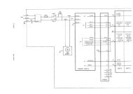
Rear View<br />
[5]<br />
[3]<br />
[4]<br />
[1]<br />
(country specific)<br />
!<br />
220–240V<br />
0.9A Max<br />
→<br />
[6]<br />
Illustration 3. Rear View<br />
[7]<br />
[2]<br />
1. Video IN: Enables an external video signal (VCR<br />
playback).<br />
2. Video OUT : Enables the connection of a video<br />
signal to external equipment (Videographic<br />
Printer, VCR Recording)<br />
3. Foot Switch Connection: An optional Foot<br />
Switch is provided as an accessory to be used in<br />
parallel with or as an alternative to the Freeze<br />
key. Enables the foot switch to freeze a real-time<br />
image.<br />
10<br />
LOGIQ α100 User Manual<br />
2211157–100 Rev 0
System Specifications<br />
Rear View (cont’d)<br />
<br />
4. Shutter: Connects the Video Graphic Printer for<br />
remote operation.<br />
5. Power Socket: Connects the main AC input.<br />
6. Circuit Breaker: The Circuit Breaker<br />
automatically shuts off power to the system in<br />
case of power overload.<br />
7. RS–232C: Used for Line Printer Interface (Serial<br />
Port only).<br />
NOTE: RS–232C Port shall be used with GE supplied<br />
cable only.<br />
Refer SV Manual 2139768 Section System Configuration<br />
for RS–232C Pin out and, Section Renewal parts for the<br />
Part number of the cable to be used.<br />
CAUTION<br />
Each outer (case) ground line of peripheral/accessory<br />
connectors are Earth Grounded. Signal ground lines are<br />
NOT Isolated.<br />
Use only approved probes, peripherals or accessories.<br />
Please refer to the Service Manual (2139768) for more<br />
information about Peripherals/Accessories and their<br />
connections.<br />
LOGIQ α100 User Manual<br />
2211157–100 Rev 0<br />
11
System Specifications<br />
Peripherals/Accessories<br />
Optional Accessories<br />
Foot Switch Connection<br />
The foot switch, which is the remote FREEZE device, is<br />
connected to the rear panel of the system. This extra<br />
FREEZE switch is provided to enhance flexibility to<br />
freeze image.<br />
Two Probe Port<br />
Trolley<br />
Video Graphic Printer<br />
The two probe port module is an option that serves as an<br />
interface to attach two probes to the single probe port of<br />
the LOGIQ α100. It enables users to change between<br />
probes by the press of a switch.<br />
The trolley is an option that serves as cart to move the<br />
LOGIQ α100 unit within a hospital. While performing a<br />
scan it offers ergonomical positions for monitor, probe<br />
holder, gel holder and Video Graphic Printer.<br />
Connect the Video Graphic printer (Sony<br />
UP–890MD/890CE) to the Video OUT provided in the<br />
rear panel of the system. Also establish shutter<br />
connection if required.<br />
Video Cassette Recorder<br />
Mount the VCR (Sony SVO–9500MD) to the Video OUT<br />
socket provided in the rear panel for recording. For<br />
playback, connect the VCR to the Video IN socket.<br />
CAUTION<br />
Use only approved probes, peripherals or accessories.<br />
Please refer to the Service Manual (2139768) for more<br />
information about Peripherals/Accessories and their<br />
connections.<br />
12<br />
LOGIQ α100 User Manual<br />
2211157–100 Rev 0
Getting Started<br />
Preparing the System for Use<br />
Operator Controls<br />
System Setup<br />
Relocating the System<br />
This section provides more details on how features of the system are used to<br />
prepare for scanning. It briefly explains each operator control on the keyboard<br />
and monitor.<br />
LOGIQ α100 User Manual<br />
2211157–100 Rev 0 13
Getting Started<br />
This page left blank intentionally.<br />
14<br />
LOGIQ α100 User Manual<br />
2211157–100 Rev 0
Preparing the System for Use<br />
Overview<br />
<br />
Only qualified physicians or sonographers should<br />
perform ultrasound scanning on human subjects for<br />
medical diagnostic reasons. Request training, if needed.<br />
Perform regular preventive maintenance. It is<br />
recommended that service is performed by the<br />
manufacturer or authorized service representatives only.<br />
Never place liquids on the unit to avoid dripping into the<br />
control panel or the unit.<br />
Ensure that unauthorized personnel do not tamper with<br />
the unit.<br />
Local Site Requirements<br />
In order to properly install the system, certain hardware<br />
must be in place and operational within the room where<br />
the console is used.<br />
Before the system arrives<br />
Ensure that the following is provided for the new system:<br />
<br />
A separate power outlet with a 5 amp circuit breaker<br />
for 120 VAC (USA) or 5 amp circuit breaker for<br />
220–240 VAC (Europe, Latin America).<br />
LOGIQ α100 User Manual<br />
2211157–100 Rev 0 15
Preparing the System for Use<br />
Before the system arrives (cont’d)<br />
<br />
<br />
Take precautions to ensure that the system is<br />
protected from electromagnetic interference.<br />
Precautions include:<br />
<br />
<br />
<br />
Operate the system at least 15 feet away from<br />
motors, typewriters, elevators, and other<br />
sources of strong electromagnetic radiation.<br />
Operation in an enclosed area (wood, plaster<br />
or concrete walls, floors and ceilings) help<br />
prevent electromagnetic interference.<br />
Special shielding may be required if the<br />
console is to be operated in the vicinity of<br />
Radio broadcast equipment.<br />
This medical equipment is approved, in terms of the<br />
prevention of radio wave interference, to be used in<br />
hospitals, clinics and other institutions which are<br />
environmentally qualified. The use of this equipment in<br />
an inappropriate environment may cause electronic<br />
interference. Refer to the LOGIQ α100 Service Manual<br />
(2139768) and this manual for details. This equipment<br />
can be used in residential areas only under the<br />
supervision of physicians or qualified sonographers.<br />
Environmental Requirements<br />
For proper functioning of the LOGIQ α100 system, care<br />
must be taken when it is transported or stored.<br />
Temperature<br />
Operational Storage Transport<br />
10 to 40 C<br />
50 to 104 F<br />
Humidity 30 to 75%<br />
non–condensing<br />
–10 to 60 C<br />
14 to 140 F<br />
30 to 90%<br />
non–condensing<br />
–40 to 60 C<br />
–40 to 140 F<br />
30 to 90%<br />
non–condensing<br />
Pressure 700 to 1060hPa 700 to 1060hPa 700 to 1060hPa<br />
Table 1. Environmental Requirements<br />
16<br />
LOGIQ α100 User Manual<br />
2211157–100 Rev 0
Preparing the System for Use<br />
Environmental Requirements (cont’d)<br />
System Acclimatization Time<br />
After being transported, the system may be cold or hot.<br />
In these circumstances, allow the unit to acclimatize<br />
before turning on. It requires one hour for each 2.5<br />
increment in temperature if the temperature is below<br />
10 C or above 40 C.<br />
C 60 55 50 45 40 35 30 25 20 15 10<br />
F 140 131 122 113 104 95 86 77 68 59 50<br />
hours 8 6 4 2 0 0 0 0 0 0 0<br />
C 5 0 –5 –10 –15 –20 –25 –30 –35 –40<br />
F 41 32 23 14 5 –4 –13 –22 –31 –40<br />
hours 2 4 6 8 10 12 14 16 18 20<br />
Table 2. System Acclimatization Time<br />
Connecting and Using the System<br />
Keyboard Preparation<br />
Unlock the keyboard by pressing the lever on the front<br />
panel.<br />
Power Cord<br />
Adhere to the electrical power rating. The system is<br />
adaptable to 100/120 Volts or 220/240 Volts. Plug the<br />
system power plug into the AC outlet which is located in<br />
the rear panel.<br />
LOGIQ α100 User Manual<br />
2211157–100 Rev 0 17
Preparing the System for Use<br />
Power Cord (cont’d)<br />
To connect the system to the power supply:<br />
1. Ensure that the wall outlet is of the appropriate<br />
type.<br />
2. Make sure that the power switch is turned off.<br />
3. Unwrap the Power Cord. Ensure sufficient slack<br />
in the cable so that the plug is not pulled out of<br />
the wall if the system is moved slightly.<br />
4. Push the power plug securely into the wall.<br />
WARNING<br />
To avoid risk of fire, the system power must be supplied<br />
from a separate properly rated outlet.<br />
The system is supplied with a power cord. Under no<br />
circumstances should this cord be altered or changed.<br />
To assure grounding reliability, connect a ‘hospital grade’<br />
or ‘hospital only’ grounded power outlet.<br />
<br />
<br />
115 VAC, 140 VA<br />
Plug and Outlet Configuration<br />
(USA)<br />
220 VAC, 170VA<br />
Plug and Outlet Configuration<br />
(Europe)<br />
Illustration 4. Example Plug and Outlet Configurations<br />
18<br />
LOGIQ α100 User Manual<br />
2211157–100 Rev 0
Preparing the System for Use<br />
Circuit Breaker<br />
5<br />
The Circuit Breaker is located on the rear panel of the<br />
console. If the Circuit Breaker is ON power is provided to<br />
the system, if it is OFF it removes power to the system. It<br />
automatically shuts OFF power to the system if a power<br />
overload occurs.<br />
If a power overload occurs:<br />
1. Switch OFF all peripherals.<br />
2. Switch OFF the main power switch to the console.<br />
3. Reactivate the Circuit Breaker switch.<br />
The Circuit Breaker switch should stay in the ON<br />
position. If the Circuit Breaker does not remain in the ON<br />
position (or trips again):<br />
1. Disconnect the power cord.<br />
2. Call Service immediately.<br />
DO NOT attempt to use the system.<br />
Foot Switch Connection (Optional)<br />
The foot switch, which is the remote FREEZE device, is<br />
connected to the rear panel of the system. This optional<br />
foot switch may be used in parallel with or as an<br />
alternative to the FREEZE key to enhance flexibility to<br />
freeze an image. Use only the GE recommended foot<br />
switch.<br />
LOGIQ α100 User Manual<br />
2211157–100 Rev 0 19
Preparing the System for Use<br />
Power ON/OFF<br />
Power ON Process<br />
The POWER ON/OFF switch is located on the front<br />
panel. To turn the power ON, press the “I” (ON) position<br />
on the power switch, the Circuit Breaker on the rear<br />
panel must also be in the ‘ON’ position. The following<br />
happens:<br />
ON<br />
OFF<br />
Illustration 5. Power On/Off<br />
1. The system is initialized during this time:<br />
<br />
<br />
<br />
A beep is heard.<br />
The two LED’s, FREEZE and EXTERNAL<br />
VIDEO, blink and go off.<br />
System diagnostics run. Its status is reflected<br />
on the monitor.<br />
20<br />
LOGIQ α100 User Manual<br />
2211157–100 Rev 0
Preparing the System for Use<br />
Power ON Process (cont’d)<br />
Ver 4.0<br />
Illustration 6. Power Up Graphic<br />
<br />
<br />
Probes are initialized for immediate operation.<br />
After a few seconds the B-Mode display<br />
appears and other preset parameters like the<br />
Dynamic Range, Gain, Depth, Near and Far<br />
Gain, Scale, Map, Frame Averaging and<br />
Image Inverse and Image Reverse will take<br />
effect.<br />
If an error occurs, an error message appears on the<br />
screen. Refer to page 311 for more information.<br />
Power Off Process<br />
To turn the power OFF, press the “O” (OFF) position on<br />
the power switch. (Refer to Illustration 5.)<br />
1. Do not pull the power cable or turn off the circuit<br />
breaker.<br />
2. Store the probe in the probe holder at the side of<br />
the system. Clean or sanitize the probe as<br />
necessary (Refer page 263).<br />
3. If daily maintenance is to be performed, turn off<br />
the circuit breaker on the rear panel.<br />
LOGIQ α100 User Manual<br />
2211157–100 Rev 0 21
Preparing the System for Use<br />
Probe Connection<br />
Use only approved probes. Probes can be connected or<br />
disconnected from the system at any time regardless of<br />
whether the system is powered ON or OFF.<br />
Connecting a probe<br />
1. Carefully unwrap the probe cord.<br />
2. Do not allow the probe head to hang free. Impact<br />
to the probe head could result in irreparable<br />
damage.<br />
3. Ensure probe ‘connector lock’ lever points<br />
towards the 12 o’clock position. (See<br />
Illustration 7.)<br />
4. Align the connector with the probe port and<br />
carefully push into place.<br />
5. Turn the ‘connector lock’ to the 3 o,clock position<br />
to secure the probe connector.<br />
6. Carefully position the probe cord so that it is free<br />
to move and is not resting on the floor.<br />
<br />
When a probe is connected, the system will automatically<br />
initialize the probe.<br />
Until the Probe is connected to the system, a ‘?’ will<br />
appear at the left top corner of the screen.<br />
22<br />
LOGIQ α100 User Manual<br />
2211157–100 Rev 0
Preparing the System for Use<br />
Disconnecting a probe<br />
1. Move the probe connector lock towards the 12<br />
o’clock position.<br />
2. Pull the probe connector straight out of the probe<br />
port.<br />
3. Carefully slide the probe connector away from the<br />
probe port.<br />
4. Ensure the cable is free.<br />
5. Be sure that the probe head is clean before<br />
placing the probe into the probe holder at the side<br />
of the system.<br />
Illustration 7. Probe Connection/Disconnection<br />
Probe Storage<br />
It is recommended that all probes be stored carefully.<br />
Store the probe in the probe holder at the side of the<br />
system when the system is being transported or put the<br />
probe into the probe box. Additional probes should be<br />
stored in their original shipping carton.<br />
LOGIQ α100 User Manual<br />
2211157–100 Rev 0 23
Preparing the System for Use<br />
Adjustment of Monitor Contrast and Brightness<br />
Adjustment of monitor CONTRAST and BRIGHTNESS is<br />
one of the most important factors for proper image<br />
quality and it should be adjusted according to the lighting<br />
in the room. If these controls are set incorrectly, the Gain<br />
and Dynamic Range may have to be changed more often<br />
than necessary to give the required image quality.<br />
1. Turn the CONTRAST Rotary Pot, which is<br />
positioned on the inclined face of the front panel,<br />
clockwise or counterclockwise to get a sharp<br />
image and a complete range of gray shades. The<br />
lowest level of black should just disappear into<br />
the background and the highest white should be<br />
bright but not saturated.<br />
2. Similarly, turn the BRIGHTNESS Rotary Pot,<br />
which is positioned above the Contrast Rotary<br />
Pot, clockwise or counterclockwise to increase<br />
the brightness until the background is just one<br />
shade above black.<br />
Brightness<br />
Contrast<br />
Illustration 8. Brightness/Contrast Adjustments<br />
24<br />
LOGIQ α100 User Manual<br />
2211157–100 Rev 0
Connection of Peripherals and Accessories<br />
Preparing the System for Use<br />
LOGIQ α100 peripherals and accessories can be<br />
properly connected using the rear panel. Refer to<br />
page 12 for more details.<br />
Located on the rear panel are VIDEO IN/OUT<br />
connections which can connect the Video Graphic Printer<br />
or VCR. Those connections are:<br />
<br />
<br />
<br />
<br />
<br />
the foot switch connection for the optional foot switch<br />
the power connector for the power cord<br />
the shutter which connects the Video Graphic Printer<br />
for remote operation.<br />
RS–232C for printer interface (Serial port only).<br />
NOTE: RS–232C Port shall be used with GE supplied<br />
cable only.<br />
Refer SV Manual 2139768 Section System Configuration<br />
for RS–232C Pin out and, Section Renewal parts for the<br />
Part number of the cable to be used.<br />
!<br />
220–240V<br />
0.9A Max<br />
(country<br />
specific)<br />
→<br />
Illustration 9. Rear Panel<br />
LOGIQ α100 User Manual<br />
2211157–100 Rev 0 25
Preparing the System for Use<br />
This page left blank intentionally.<br />
26<br />
LOGIQ α100 User Manual<br />
2211157–100 Rev 0
Operator Controls<br />
Keyboard Controls<br />
Keyboard Layout<br />
The keyboard is used for functions like data entry, image<br />
optimization, annotation and measurements/calculations.<br />
Illustration 10. Keyboard Control Layout<br />
LOGIQ α100 User Manual<br />
2211157–100 Rev 0<br />
27
Operator Controls<br />
Key Description<br />
New Patient<br />
ID/Name<br />
WARNING<br />
Preset<br />
←<br />
Comment<br />
Selection<br />
Press NEW PATIENT at the beginning of each patient<br />
study. Pressing the NEW PATIENT key prompts the<br />
system for the new patient entry menu. Press CLEAR to<br />
abort the new patient data entry if required. Pressing<br />
NEW PATIENT a second time clears all previous patient<br />
data, annotations, measurements, calculations and<br />
summary report pages from the system’s memory and<br />
accepts the new entry and exits the menu.<br />
Press ID/NAME to enter or replace patient data without<br />
changing the current status of the system. Pressing the<br />
ID/NAME key enables the Patient Entry Menu. Enter<br />
Patient ID/Name using alphanumeric keys. Press<br />
CLEAR to abort the ID/Name menu if required. Press<br />
ID/NAME a second time (or RETURN) to exit the menu<br />
and display ID/NAME on the image display.<br />
To avoid patient identification errors, always verify the<br />
identification with the patient. Make sure the correct<br />
patient identification appears on all screens and hard<br />
copy prints.<br />
Press PRESET to select the default scan parameters<br />
stored for the probe connected. Parameters can be<br />
predefined using the Control–W function.<br />
Press COMMENT to enter comments anywhere on the<br />
image area. Use the TRACKBALL, SPACE OR<br />
RETURN to move the cursor.<br />
Press SELECTION to select a body pattern from the<br />
currently active body pattern package. Pressing the<br />
SELECTION key at the end of each menu (either<br />
Abdomen or OB/GYN) takes you to the next Body<br />
Pattern Package automatically.<br />
28<br />
LOGIQ α100 User Manual<br />
2211157–100 Rev 0
Key Description (continued)<br />
<br />
Rotate<br />
Measurement<br />
Clear<br />
<br />
Operator Controls<br />
The Left and Right Body Pattern ROTATION keys rotate<br />
the probe marker on the selected body pattern. When<br />
Body Pattern is not active, use the rotate keys to select<br />
next/previous options in the measurement menu. These<br />
keys are also used to move between the OB Report<br />
Page, the Measurement Averaging Page and the<br />
Anatomical Survey Page.<br />
Press MEASUREMENT to start measurement<br />
procedures and enable calculations. The<br />
MEASUREMENT key also toggles the movable cursor<br />
during Ellipse adjustment and distance measurements.<br />
The CLEAR key clears measurements, comments, help<br />
screen and terminates control sequences in the order in<br />
which they are done.<br />
Near Far<br />
Dyn. Range<br />
Scroll<br />
NEAR Gain controls the overall gain in the near field of<br />
the image up to 20mm depth. FAR Gain controls the<br />
overall gain in the far field of the image beyond 20mm<br />
depth. The NEAR Gain controls are also used to<br />
activate the Ellipse Measurement function after the first<br />
distance measurement has been set.<br />
DYNAMIC RANGE adjusts the intensities of returning<br />
echoes. The echoes are converted into visual shades of<br />
gray. Adjusting the dynamic range thus affects the range<br />
of shades displayed. Increase dynamic range to get a<br />
smoother image. Decrease dynamic range to achieve an<br />
image with more contrast.<br />
SCROLL ← →↑↓ enables scrolling the live image<br />
Left/Right, Up/Down on the Display in B–Mode. Scrolling<br />
Up/Down in M-Mode is possible. Scrolling Left/Right in<br />
M–Mode is not possible.<br />
LOGIQ α100 User Manual<br />
2211157–100 Rev 0<br />
29
Operator Controls<br />
Key Description (continued)<br />
Gain/Rotate<br />
Depth<br />
The GAIN/ROTATE knob adjusts the amplification of the<br />
returning echoes in both B- and M-Modes. When the<br />
image is frozen, this knob acts as a ROTATE knob used<br />
for rotating the probe marker on body patterns and the<br />
lines in Hip Dysplasia.<br />
DEPTH determines the depth of the image displayed.<br />
Refer page 259 for Depth details.<br />
Focus<br />
FOCUS enables the selection of the optimal focal depth<br />
for transmit. A focus marker on the right side of the<br />
display indicates the image area which is focussed. Two<br />
focus markers appear in Combination Focus mode.<br />
B<br />
M<br />
B MODE (Brightness Mode) format appears as a default<br />
when the system is turned on.<br />
M MODE (Motion Mode) toggles between B/M- and<br />
M-Mode formats.<br />
*A MODE (Amplitude Mode) –Use M key to go to B/M.<br />
Use CONTROL Q to toggle between B/A and B/M.<br />
* Applicable only for systems delivered in India.<br />
L<br />
R<br />
ÀÀ<br />
ÀÀ<br />
The LEFT/RIGHT keys are used to display dual B-Mode<br />
images. The left image appears after the Left key is<br />
pressed. Pressing the Right key freezes the left image<br />
while activating the right image. Press FREEZE to<br />
freeze the active image.<br />
30<br />
LOGIQ α100 User Manual<br />
2211157–100 Rev 0
Key Description (continued)<br />
Ext. Video<br />
<br />
<br />
Record<br />
Freeze<br />
<br />
Operator Controls<br />
EXTERNAL VIDEO enables an external video signal<br />
(VCR playback) to be viewed on the LOGIQ α100<br />
system monitor. A LED lights when the key is pressed. It<br />
is a toggle key.<br />
RECORD is used to trigger a device like a videographic<br />
printer to print images or report pages appearing on the<br />
display monitor.<br />
FREEZE is used to stop the acquisition of ultrasound<br />
data on a displayed image and freeze the image in<br />
system memory. If pressed again, it unfreezes the image<br />
and erases all measurements from the screen and<br />
continues live image acquisition.<br />
Press BACK SPACE to erase individual characters to the<br />
left of the cursor while entering alphanumeric information.<br />
Return<br />
Set<br />
Press RETURN to go to the next line of annotation. It can<br />
also be used to go from one field to the next in the<br />
Installation Setup Menu, the European OB Table Setup<br />
Menu, OB Report Pages and the New Patient, ID/Name<br />
Menu.<br />
Press SET to start or finish an operation.<br />
Reverse<br />
Press REVERSE key to reverse the image from Left to<br />
Right. Press a second time to reverse the image from<br />
Right to Left.<br />
Press SHIFT + REVERSE to invert the image from Top to<br />
Bottom. Press a second time to invert the image from<br />
Bottom to Top.<br />
LOGIQ α100 User Manual<br />
2211157–100 Rev 0<br />
31
Operator Controls<br />
Key Description (continued)<br />
Ctrl<br />
Enter<br />
CONTROL/ENTER is used along with certain<br />
alphanumeric keys to activate all control functions. Refer<br />
Chapter Control Keys on page 237 for more details.<br />
When CONTROL/ENTER is pressed a second time, it is<br />
used to execute an operation. It is also used in the<br />
following contexts:<br />
to come out of report pages and OB User Table Editor<br />
to go from one field to the next in the<br />
Installation Setup Menu and the European OB Table<br />
Setup Menu.<br />
SPACE is used to enter a distance between 2 characters<br />
or words.<br />
TRACKBALL is used with Measurement and Annotation<br />
functions. TRACKBALL control depends on the last<br />
function key pressed.<br />
Hints<br />
If an error is detected that limits operation, press CLEAR<br />
to clear the operation.<br />
32<br />
LOGIQ α100 User Manual<br />
2211157–100 Rev 0
System Setup<br />
Setup Procedure<br />
After connecting the system, set up the system by following the procedure<br />
listed below:<br />
Ctrl<br />
Enter<br />
S<br />
Press CTRL–S1 ENTER for the Installation Setup menu,<br />
an Installation Setup window appears. When this function<br />
is enabled, the image, measurements, body patterns and<br />
comments (if any) are temporarily removed from the<br />
screen.<br />
1<br />
Ctrl<br />
Enter<br />
Illustration 11 Installation Setup Menu<br />
INSTALLATION SETUP<br />
1. HOSPITAL NAME:<br />
2. DATE FORMAT: 1<br />
1:DD/MM/YY 2:MM/DD/YY 3:YY/MM/DD)<br />
3. DATE: XX/XX/XX 4.TIME: XX:XX<br />
5.OB VERSION SELECTED: 1<br />
(1:US 2:TOKYO 3:OSAKA 4:EUROPE 5:ASUM)<br />
6.FILM EXPOSURE TIME: 4<br />
(1:125ms 2:250ms 3:375ms 4:500ms)<br />
7.MINIMUM FILM EXPOSURE INTERVAL : 2 (1–9 seconds)<br />
8.VIDEO INVERT FOR REPORT PRINT : 2 (1:YES2:NO)<br />
9.CIRCUMFERENCE MEASUREMENT METHOD: 1<br />
(1:ELLIPSE 2:2DISTANCE 3:TRACE)<br />
10. US GA SELECTION : 1(1:CUA 2:AUA)<br />
11. ADD 1 WEEK TO EDD : 1 (1:NO 2:YES)<br />
12. LANGUAGE : 1 (1:ENG 2:GER 3:FRE 4:ITA 5:POR 6:SPA)<br />
13. HIP ORIENTATION:1 (1.CRANIAL LEFT 2.CAUDAL LEFT)<br />
LOGIQ α100 User Manual<br />
2211157–100 Rev 0<br />
33
System Setup<br />
Setup Procedure (cont’d)<br />
Use the TRACKBALL, SHIFT ↑↓← → , CTRL/ENTER or<br />
RETURN keys to move from up/down, or left/right to edit<br />
the fields. Use BACK SPACE to delete a character to the<br />
left of the cursor.<br />
Press SET to register the inputs and return to the original<br />
display. Pressing any other key would result in a beep,<br />
indicating it is an error.<br />
Press CLEAR to return to the original display without<br />
registering any inputs.<br />
34<br />
LOGIQ α100 User Manual<br />
2211157–100 Rev 0
Relocating the System<br />
Moving the system<br />
When moving or transporting the system, follow the<br />
precautions below to ensure maximum safety of<br />
personnel, system and other equipments.<br />
1. Switch OFF power to the system.<br />
2. All cables connecting the peripherals (Video<br />
Graphic Printer, etc.) should be disconnected<br />
from the system.<br />
3. Ensure that no loose items are left on the<br />
console.<br />
4. Lock the keyboard onto the front panel.<br />
5. Wrap the system’s power cord securely onto the<br />
hooks on the rear side of the system.<br />
6. Put the probe into the probe holder or the probe<br />
box provided with the probes.<br />
7. Put the gel bottle into the gel holder at the side of<br />
the system.<br />
8. Carry the equipment by grasping the handle on<br />
top of the system.<br />
9. When using the Two Probe Port Option do not<br />
carry the system with the probes connected to the<br />
Two Probe Port. This will avoid damage to the<br />
probe connectors. Always carry the equipment<br />
with the Two Probe Port facing away from your<br />
body.<br />
CAUTION<br />
Do not apply any pressure on the system. Make sure the<br />
handle is free from any oil, gel or any slippery substance<br />
which may cause the system to drop.<br />
LOGIQ α100 User Manual<br />
2211157–100 Rev 0<br />
35
Relocating the System<br />
Transporting the system<br />
Use extra care when transporting the system using<br />
vehicles. Follow precautions below:<br />
1. Keep the unit upright.<br />
2. Prevent vibration damage by driving cautiously.<br />
Avoid unpaved roads, excessive speeds and<br />
sudden stops and starts.<br />
36<br />
LOGIQ α100 User Manual<br />
2211157–100 Rev 0
Safety<br />
Precaution Levels<br />
Hazard Symbols<br />
Patient Safety<br />
Equipment and Personnel Safety<br />
Device Labels<br />
Warning Labels/Locations<br />
This section is important in order to become familiar with precaution levels and<br />
hazard symbols used in this manual and on the system. It explains patient,<br />
system and personnel safety concerns. The controls that affect acoustic output<br />
levels are shown in table form.<br />
LOGIQ α100 User Manual<br />
2211157–100 Rev 0<br />
37
Safety<br />
This page left blank intentionally.<br />
38<br />
LOGIQ α100 User Manual<br />
2211157–100 Rev 0
Precaution Levels<br />
Overview<br />
This section is important in order to become familiar with<br />
precaution levels and hazard symbols used in this<br />
manual and on the system. It explains patient, system<br />
and personnel safety concerns. The controls that affect<br />
acoustic output levels are shown in the form of a table.<br />
Before using the machine, study the manual. Carefully<br />
review the manual periodically for warnings, safety<br />
precautions and maintenance requirements to avoid<br />
conditions that could result in injury.<br />
Icon Description<br />
Precautionary statements and warning labels are<br />
provided in various locations on the LOGIQ α100<br />
console and throughout this manual to alert the user to<br />
hazards or situations that could result in injury or<br />
equipment damage. Symbols are often used with these<br />
warnings to increase user awareness and emphasize<br />
particular hazards. The user should become familiar with<br />
the meaning of symbols and the intent of all product<br />
warnings and precautionary statements.<br />
DANGER<br />
Indicates that a specific hazard is known to exist which<br />
through inappropriate conditions or actions will cause:<br />
<br />
<br />
Severe or fatal personal injury.<br />
Substantial property damage.<br />
LOGIQ α100 User Manual<br />
2211157–100 Rev 0<br />
39
Precaution Levels<br />
Icon Description (cont’d)<br />
WARNING<br />
Indicates that a specific hazard is known to exist which<br />
through inappropriate conditions or actions may cause:<br />
<br />
<br />
Severe personal injury.<br />
Substantial property damage.<br />
CAUTION<br />
<br />
<br />
FOR<br />
USA<br />
ONLY<br />
Indicates that a potential hazard may exist which through<br />
inappropriate conditions or actions will or can cause:<br />
<br />
<br />
Minor injury.<br />
Property damage.<br />
Indicates precautions or prudent use recommendations<br />
that should be used in the operation of the ultrasound<br />
system, specifically:<br />
<br />
<br />
<br />
<br />
Use of the ultrasound system as a prescription device<br />
under the order of the physician.<br />
Noting or emphasizing a necessary operator<br />
action.<br />
Maintaining an optimum system environment.<br />
Step or time saving recommendations.<br />
40<br />
LOGIQ α100 User Manual<br />
2211157–100 Rev 0
Hazard Symbols<br />
Icon Description<br />
Potential hazards are indicated by the following icons:<br />
Icon<br />
Biological<br />
Hazard<br />
Electrical<br />
Hazard<br />
Acoustic<br />
Output<br />
Hazard<br />
Explosion<br />
Hazard<br />
Potential<br />
Hazard Usage Source<br />
Patient/user<br />
infection due to<br />
contaminated<br />
equipment.<br />
Electrical microshock<br />
to<br />
patient, e.g.,<br />
ventricular<br />
fibrillation<br />
initiated.<br />
Electrical<br />
macroshock<br />
to<br />
patient/<br />
user.<br />
Patient injury or<br />
tissue damage<br />
from ultrasound<br />
radiation.<br />
Risk of<br />
explosion if<br />
used in the<br />
presence of<br />
flammable<br />
anesthetics.<br />
Cleaning and<br />
care<br />
instructions<br />
Sheath and<br />
glove guidelines<br />
Probes<br />
ECG<br />
Connections to<br />
rear panel<br />
ALARA, the use<br />
of acoustic<br />
output following<br />
the as low as<br />
reasonably<br />
achievable<br />
principle<br />
Keep away form<br />
flammable<br />
anesthetic<br />
ISO 7000<br />
No. 0659<br />
Table 3. Potential Hazards<br />
LOGIQ α100 User Manual<br />
2211157–100 Rev 0<br />
41
Hazard Symbols<br />
Icon Description (cont’d)<br />
Icon<br />
Smoke<br />
& Fire<br />
Hazard<br />
Non–<br />
Ionizing<br />
Radiation<br />
Potential<br />
Hazard Usage Source<br />
Patient/user<br />
injury or<br />
adverse<br />
reaction from<br />
fire or smoke.<br />
Patient/user<br />
injury from<br />
explosion and<br />
fire.<br />
Console<br />
failure, erratic<br />
operation or<br />
output error<br />
due to RF<br />
interference.<br />
Replacing<br />
fuses<br />
Outlet<br />
guidelines<br />
RF IEC 878<br />
No. 03-04<br />
Table 3. Potential Hazards (cont’d)<br />
Important Safety Considerations<br />
The following sections (Patient Safety, and Equipment<br />
and Personnel Safety) are intended to make the<br />
equipment user aware of particular hazards associated<br />
with the use of this equipment and the extent to which<br />
injury can occur if precautions are not observed.<br />
Additional precautions may be provided throughout the<br />
manual. The equipment user is obligated to be familiar<br />
with these concerns and avoid conditions that could<br />
result in injury.<br />
42<br />
LOGIQ α100 User Manual<br />
2211157–100 Rev 0
Patient Safety<br />
Related Hazards<br />
The concerns listed below can seriously affect the safety<br />
of patients undergoing a diagnostic ultrasound<br />
examination.<br />
Patient<br />
Identification<br />
Diagnostic<br />
Information<br />
Patient ID/Name should be entered accurately. Make<br />
sure correct patient ID is provided on all recorded data<br />
and hard copy prints. Identification errors could result in<br />
an incorrect diagnosis.<br />
Equipment malfunction or incorrect settings can result in<br />
measurement errors or failure to detect details within the<br />
image. The equipment user must become thoroughly<br />
familiar with the equipment operation in order to optimize<br />
its performance and recognize possible malfunctions.<br />
Applications training is available through your local GE<br />
representative. Added confidence in your equipment<br />
operation can be gained by establishing a quality<br />
assurance program.<br />
Only qualified physicians and sonographers should<br />
perform Ultrasound scanning on human subjects for<br />
medical diagnostic reasons. Exposure levels to be kept<br />
to minimum and to be consistent with recommended<br />
practices for diagnostic evaluation.<br />
Clinical Diagnosis<br />
Calculation formulas and data base are provided only as<br />
a tool and should not be the basis in which clinical<br />
diagnosis can be made. The user is encouraged to<br />
research the articles and sample the output data from<br />
this device and make a judgement as to the utility of this<br />
and calculation results as a clinical tool.<br />
LOGIQ α100 User Manual<br />
2211157–100 Rev 0<br />
43
Patient Safety<br />
Related Hazards (cont’d)<br />
Mechanical<br />
Hazards<br />
Electrical<br />
Hazard<br />
Damaged probes or improper use and manipulation of<br />
intracavitary probes can result in injury or increased risk<br />
of infection. Handle the probes with care. They may be<br />
damaged if dropped or mishandled. A damaged probe<br />
has to be scrapped. It cannot be repaired or reused. Do<br />
not allow the lens to come into contact with a sharp<br />
object or to be knocked against an object. Be sure to put<br />
the transducers in the side slot before transporting.<br />
A damaged probe may cause an electrically hazardous<br />
condition if conductive solutions come in contact with<br />
internal live parts. Do not use any probe with damaged<br />
lens to scan a patient. Inspect probes often for cracks or<br />
openings which could allow liquid entry.<br />
To avoid electrical shock, use only the supplied power<br />
cords and connect them only to properly grounded (three<br />
hole) wall outlets. Do not use a 2 prong–adaptor.<br />
The system should be operated within the voltage limits<br />
defined in Standard Specifications on page 5.<br />
Do not place liquids on or above the console. If the<br />
liquid spills, it may come in contact with live parts and<br />
increase the risk of shock.<br />
This system contains no operator serviceable<br />
components. Do not remove the system covers. Only<br />
qualified Service personnel should service the system.<br />
Accidentally contacting the electrical circuits inside the<br />
housing could cause serious injury. Do not use with<br />
defibrillators.<br />
44<br />
LOGIQ α100 User Manual<br />
2211157–100 Rev 0
Patient Safety<br />
Related Hazards (cont’d)<br />
Acoustic<br />
Output<br />
Hazard<br />
Although there have been no confirmed adverse effects<br />
produced by diagnostic levels of ultrasound, avoid<br />
unnecessary exposure of ultrasound energy to the<br />
human body. Wrong scan settings, probe positioning and<br />
tissue type can result in injury. Use the minimum<br />
necessary output to get the best diagnostic image or<br />
measurement during an examination. Begin an exam<br />
with a probe that provides optimum focal depth and<br />
penetration.<br />
Follow the principle of “as low as reasonably achievable”<br />
(ALARA) when scanning patients. Once an optimal<br />
image is achieved, the need for prolonging the exposure<br />
cannot be justified.<br />
The principle of ALARA, which stands for “As Low As<br />
Reasonably Achievable”, is to keep the radiation<br />
exposure at the minimum level necessary to obtain the<br />
diagnostic information. This principle is widely practiced<br />
in medical X–ray protection where exposure at any level<br />
is potentially harmful. Historically, ALARA was initiated as<br />
a cautious approach for dealing with uncertain hazards<br />
but has since become the principle method for reducing<br />
the risk of injury from hazards that do not have safe<br />
minimum thresholds.<br />
While no minimum thresholds for harmful bio-effects<br />
have been established with the use of diagnostic<br />
ultrasound, the principle of ALARA can be readily<br />
implemented on equipment incorporating an output<br />
display. As the operator adjusts the equipment to<br />
optimize the image quality, the display interactively<br />
updates to indicate the effect on output.<br />
LOGIQ α100 User Manual<br />
2211157–100 Rev 0<br />
45
Patient Safety<br />
This page left blank intentionally.<br />
46<br />
LOGIQ α100 User Manual<br />
2211157–100 Rev 0
Equipment and Personnel Safety<br />
Related Hazards<br />
The concerns listed below can seriously affect the safety<br />
of the equipment and personnel during a diagnostic<br />
ultrasound examination.<br />
Explosion<br />
Hazard<br />
Do not operate the system in the presence of flammable<br />
anesthetics. The system is not designed for such use,<br />
since it can lead to an explosion.<br />
WARNING<br />
This equipment contains dangerous voltages that can<br />
cause serious injury or death.<br />
Electrical<br />
Hazard<br />
Smoke<br />
& Fire<br />
Hazard<br />
To avoid injury:<br />
<br />
<br />
<br />
Do not remove protective covers. No user serviceable<br />
parts inside. Refer servicing to qualified service<br />
personnel.<br />
To assure adequate grounding, connect the power<br />
plug to a reliable (hospital grade) grounding outlet<br />
(having a equalization conductor ).<br />
Do not place liquids on or above the console. Spilled<br />
liquid may contact live parts and increase the risk of<br />
shock.<br />
The system must be supplied from an adequately rated<br />
power outlet. The capacity of the power outlet must be as<br />
specified in the LOGIQ α100 Service Manual<br />
(2139768).<br />
LOGIQ α100 User Manual<br />
2211157–100 Rev 0<br />
47
Equipment and Personnel Safety<br />
Related Hazards (cont’d)<br />
<br />
FOR<br />
Biological<br />
Hazard<br />
USA<br />
ONLY<br />
For patient and personnel safety beware of biological<br />
hazards while performing invasive procedures. To avoid<br />
the risk of disease transmission:<br />
<br />
<br />
<br />
Use protective barriers like FDA cleared gloves and<br />
probe sheaths. Follow sterile procedures when<br />
appropriate.<br />
Thoroughly clean probes and reusable accessories<br />
after each patient examination and disinfect or<br />
sterilize as needed. Refer to page 263 for details.<br />
Follow all infection control policies established by<br />
your office, department or institution as they apply to<br />
personnel and equipment.<br />
Caution: United States law restricts the device to<br />
sale or use by or on the order of the physician.<br />
CAUTION<br />
Devices containing latex may cause severe allergic<br />
reaction in latex sensitive individuals. USA customers<br />
should refer to the FDA’s March 29, 1991 Medical Alert<br />
on latex products.<br />
48<br />
LOGIQ α100 User Manual<br />
2211157–100 Rev0
Device Labels<br />
Label Icon Description<br />
The following table describes the purpose and location of<br />
safety labels and other important information provided on<br />
the equipment.<br />
Label Publication Description Location<br />
IEC 417–5032<br />
IEC 417–5019<br />
Alternating Current Single<br />
Phase<br />
Protective earth<br />
(grounding)<br />
Rear Panel<br />
Internal<br />
IEC 417–5036<br />
IEC 417–5007<br />
Warning, High Voltage<br />
ON (Power: connection<br />
to the Mains)<br />
On the CRT,<br />
on the fly back<br />
transformer<br />
Front Panel<br />
IEC 417–5008<br />
OFF (Power: disconnection<br />
from the Mains)<br />
Front Panel<br />
IEC 417–5056<br />
Brightness<br />
Front Panel<br />
IEC 417–5057<br />
Contrast<br />
Front Panel<br />
IEC 878–01–36<br />
Video Input<br />
Rear Panel<br />
IEC 878–01–37<br />
Video Output<br />
Rear Panel<br />
Table 4. Device Labels (Part 1)<br />
LOGIQ α100 User Manual<br />
2211157–100 Rev 0<br />
49
Device Labels<br />
Label Icon Description (cont’d)<br />
Label/Symbol Description Location<br />
Identification and<br />
Rating Plate<br />
Type/Class Label<br />
Manufacturer’s name and address<br />
Date of Manufacture<br />
Model and Serial numbers<br />
Electrical ratings<br />
Used to indicate the degree of safety or<br />
protection<br />
Rear of<br />
Console<br />
Rear of<br />
Console<br />
Device Listing/<br />
Certification Labels<br />
“DANGER – Possible<br />
explosion hazard, if<br />
used in the presence<br />
of flammable<br />
anesthetics.”<br />
!<br />
Laboratory logo or labels denoting<br />
conformance with industry safety<br />
standards such as UL or IEC<br />
This system is not designed for use with<br />
flammable anesthetic gases<br />
“ATTENTION – Consult accompanying<br />
documents” is intended to alert the user<br />
to refer to the operator manual or other<br />
instructions when complete information<br />
cannot be provided on the label.<br />
Type BF Equipment (man in the box<br />
symbol) IEC 878–02–03 indicates<br />
B Type equipment having a floating<br />
applied part.<br />
Rear of<br />
Console<br />
External<br />
Rear of<br />
Console<br />
External<br />
“CAUTION” The equilateral triangle is<br />
usually used in combination with other<br />
symbols to advise or warn the user.<br />
Rear of<br />
Console<br />
IP Code<br />
(IPX1)<br />
Indicates degree of protection provided<br />
by the enclosure for IEC 529. IPX1 indicates<br />
drip proof.<br />
Table 5. Device Labels (Part 2)<br />
Foot Switch<br />
50<br />
LOGIQ α100 User Manual<br />
2211157–100 Rev 0
Device Labels<br />
Classifications<br />
Type of protection against electric shock: Class I EQUIPMENT *1<br />
*1. Class I EQUIPMENT<br />
EQUIPMENT in which protection against electric shock does not<br />
rely on BASIC INSULATION only, but which includes an additional<br />
safety precaution in that means are provided for the connection of<br />
the EQUIPMENT to the protective earth conductor in the fixed wiring<br />
of the installation in such a way that ACCESSIBLE METAL PARTS<br />
cannot become LIVE in the event of a failure of the BASIC<br />
INSULATION.<br />
Degree of protection against electric shock: Type BF EQUIPMENT *2<br />
*2. Type BF EQUIPMENT<br />
Type B EQUIPMENT with a F–TYPE isolated applied part providing<br />
a degree of protection against electric shock to such a degree that<br />
the allowable PATIENT LEAKAGE CURRENT under SINGLE<br />
FAULT CONDITIONS is not exceeded when 1.1 times the highest<br />
rated MAINS VOLTAGE is applied between the APPLIED PART and<br />
earth.<br />
EMC – Electromagnetic Compatibility<br />
EMC Performance<br />
All types of electronic equipment may characteristically cause<br />
electromagnetic interference with other equipment, either transmitted<br />
through air or connecting cables. The term EMC indicates the capability<br />
of the equipment to curb electromagnetic influence from other<br />
equipment and at the same time not affect other equipment with similar<br />
electromagnetic radiation from itself.<br />
This product is designed to fully comply with the EN60601–1–2<br />
(IEC601–1–2), Class A, in medical electric equipment EMC regulations.<br />
Proper installation following the service manual is required in order to<br />
achieve the full EMC performance of the product.<br />
In case of issues related to EMC, please call your service personnel.<br />
LOGIQ α100 User Manual<br />
2211157–100 Rev 0<br />
51
Device Labels<br />
EMC – Electromagnetic Compatibility (cont’d)<br />
Notice upon Installation of Product<br />
1. Use either power supply cords provided by GE Medical Systems<br />
or ones designated by GE Medical Systems. Products equipped<br />
with a power source plug should be plugged into the fixed power<br />
socket which has the protective grounding conductor. Never use<br />
any adaptor or converter to connect with a power source plug<br />
(i.e. three–prong–to–two prong converter).<br />
2. Locate the equipment as far away as possible from other<br />
electronic equipment.<br />
3. Be sure to use only the cables provided by or designated by GE<br />
Medical Systems. Connect these cables following the installation<br />
procedures (i.e. wire power cables separately from signal<br />
cables).<br />
4. Lay out the main equipment and other peripherals following the<br />
installation procedures described in the Service manual.<br />
General Information<br />
1. Designation of Peripheral Equipment Connectable to this<br />
Product, refer page 25. These Peripherals can be hooked up to<br />
the product without compromising its EMC performance.<br />
2. Avoid using equipment not designated for the LOGIQ α100.<br />
Failure to comply with this instruction may result in poor EMC<br />
performance of the product.<br />
3. Notice against User Modification:<br />
Never Modify this product. Unilateral user modification may<br />
cause degradation in EMC performance.<br />
Modification of the product includes:<br />
a. Changes in cables (length, material, wiring etc.)<br />
b. Changes in system insulation/layout.<br />
c. Changes in system configuration/components.<br />
d. Changes in securing system parts (cover open/close).<br />
52<br />
LOGIQ α100 User Manual<br />
2211157–100 Rev 0
Device Labels<br />
EMC – Electromagnetic Compatibility (cont’d)<br />
<br />
4. Operate the system with all covers closed. If a cover is opened<br />
for some reason ensure to shut it before starting/resuming<br />
operation.<br />
NOTE: Operating the system with any cover open may<br />
affect EMC performance.<br />
CAUTION<br />
Do not use the following devices near the LOGIQ α100<br />
system. Devices which intrinsically transmit radio waves<br />
such as cellular phone, radio transceiver, mobile radio<br />
transmitter radio–controlled toy, etc. Use of these devices<br />
could cause the LOGIQ α100 system to perform<br />
outside the published specifications. Keep power to<br />
these devices turned off when near the system.<br />
Medical staff in charge of the LOGIQ α100 system is<br />
required to instruct technicians, patients and other<br />
people who may be around the system to fully comply<br />
with the above regulation.<br />
LOGIQ α100 User Manual<br />
2211157–100 Rev 0<br />
53
Device Labels<br />
EMC – Electromagnetic Compatibility (cont’d)<br />
Patient Environmental Devices<br />
Acceptable Devices<br />
CAUTION<br />
Do not connect any probes or accessories without<br />
approval by GE. Those listed in Page7 have been tested<br />
and verified to be compatible with the LOGIQ α100<br />
system.<br />
Unapproved Devices<br />
CAUTION<br />
The user takes all responsibility for connecting<br />
unapproved devices. If devices are connected without<br />
the approval of GE, the warranty will be INVALID.<br />
Any devices connected to the LOGIQ α100 System must<br />
conform to one or more of the requirements listed below:<br />
IEC 50, IEC 65, IEC 335, IEC 348, IEC 414, IEC 820,<br />
IEC 950, IEC 1010–1, ISO 7767, ISO 8185, ISO<br />
8359 OR IEC 601–1.<br />
<br />
The devices should be connected to ‘Protective<br />
Earth’ (Ground).<br />
54<br />
LOGIQ α100 User Manual<br />
2211157–100 Rev 0
Warning Labels/Locations<br />
Warning Labels<br />
Danger/Caution Label<br />
!<br />
Possible explosion hazard if<br />
used in the presence of<br />
flammable anesthetics.<br />
!<br />
DANGER<br />
CAUTION<br />
Do not use with Defibrillator.<br />
__________________________<br />
United State law restricts this<br />
device to sale or use by or on the<br />
order of a physician<br />
Warning<br />
WARNING<br />
!<br />
Possible shock hazard. Do not<br />
remove Covers or Panels. Refer<br />
servicing to qualified personnel.<br />
–––––––––––––––––––––––––––<br />
For continued protection against<br />
fire or shock hazard – Replace<br />
only with same type and rating of<br />
Fuse.<br />
–––––––––––––––––––––––––––<br />
Grounding reliability can only be<br />
achieved with “<strong>Hospital</strong> only” or<br />
“<strong>Hospital</strong> Grade” cordset provided<br />
with the system<br />
Illustration 12. Warning Label Locations<br />
LOGIQ α100 User Manual<br />
2211157–100 Rev 0<br />
55
Device Labels<br />
Warning Labels (cont’d)<br />
Caution Label<br />
!<br />
CAUTION<br />
Regulatory Labels<br />
Do not use the following devices<br />
near this equipment.<br />
Cellular phone, radio transceiver,<br />
mobile radio transmitter,<br />
radio–controller toy, etc.<br />
Use of these devices could cause<br />
this equipment to perform outside<br />
the published specifications.<br />
Keep power to these devices<br />
turned off when near this<br />
equipment.<br />
Illustration 12. Warning Label Locations (cont’d)<br />
56<br />
LOGIQ α100 User Manual<br />
2211157–100 Rev 0
Device Labels<br />
Warning Labels (cont’d)<br />
MODEL :<br />
CLASS I<br />
MANUFACTURED :<br />
LOCATION : Wipro GE Medical Systems Ltd.<br />
Bangalore, India<br />
Rating Plate<br />
Made for GE Medical Systems,<br />
Milwaukee, Wisconsin by<br />
Wipro GE Medical Systems Ltd.,<br />
Bangalore, INDIA<br />
SERIAL :<br />
VOLTS : V, PHASE I<br />
AMP LONG TERM : AMP<br />
FREQUENCY : 50/60 Hz<br />
For Europe<br />
50/60<br />
For Asia & America<br />
Illustration 12. Warning Label Locations (cont’d)<br />
LOGIQ α100 User Manual<br />
2211157–100 Rev 0<br />
57
Device Labels<br />
This page left blank intentionally.<br />
58<br />
LOGIQ α100 User Manual<br />
2211157–100 Rev 0
Scan Procedures<br />
Patient Registration<br />
Image Display<br />
Scan Adjustments<br />
VCR Operations<br />
Two Probe Port<br />
This section describes the basic elements of the system and it displays common<br />
types of modes of scanning.<br />
This section is a guide to perform a scan. It includes scan adjustments required<br />
to get optimal image display.<br />
LOGIQ α100 User Manual<br />
2211157–100 Rev 0<br />
59
Safety<br />
This page left blank intentionally.<br />
60<br />
LOGIQ α100 User Manual<br />
2211157–100 Rev 0
Patient Registration<br />
Introduction<br />
Turn ON the System by pressing the POWER Switch to<br />
the “I” (ON) position. The system beeps once and runs a<br />
self test. The system defaults to B-Mode format.<br />
Patient Registration Procedure<br />
Begin an exam by entering new patient information.<br />
Press the NEW PATIENT key at the beginning of each<br />
patient study. A patient data entry menu appears on the<br />
monitor. Enter Patient Identification (16 characters)<br />
using alphanumeric keys, press RETURN to go to the<br />
Patient Name field (28 characters). Enter Patient Name.<br />
Press RETURN or NEW PATIENT to register the inputs<br />
and exit out of the menu<br />
Press CLEAR to exit NEW PATIENT and abort entry if<br />
required.<br />
or<br />
LOGIQ α100 User Manual<br />
2211157–100 Rev 0<br />
61
Patient Registration<br />
Patient Registration Procedure (cont’d)<br />
NEW PATIENT<br />
ID: (Up to 16 chars)<br />
NAME: (Up to 28 chars)<br />
Press “New Patient” to enter new data and exit<br />
Press “Clear” to cancel and exit<br />
Return<br />
Register and exit Register and exit Abort/Exit<br />
<br />
Illustration 13. New Patient Entry<br />
NOTE: To modify only Patient Information without<br />
erasing other data, press the ID/NAME key. Pressing<br />
ID/NAME allows modification of patient data without<br />
erasing patient image, measurements, calculations and<br />
summary reports.<br />
Patient Scan Procedure<br />
Pressing NEW PATIENT key twice, clears all patient<br />
data, annotations, measurements, calculations and<br />
summary report pages from the system’s memory.<br />
1. Position the patient in a lying down position and<br />
apply Acoustic gel to the probe and on the<br />
patient. Position the transducer on the patient,<br />
adjust the imaging controls to produce a high<br />
quality image.<br />
2. Begin the scan on the patient.<br />
62<br />
LOGIQ α100 User Manual<br />
2211157–100 Rev 0
Patient Registration<br />
Patient Scan Procedure (cont’d)<br />
3. A real-time image appears on the monitor through<br />
the following controls:<br />
<br />
<br />
<br />
<br />
<br />
<br />
Orient the probe on the patient based on the<br />
study to be performed or view to be obtained.<br />
Increase or decrease the overall GAIN, NEAR<br />
and FAR gain controls and DYNAMIC RANGE<br />
to obtain the desired Image quality.<br />
If the image is not bright, increase the overall<br />
‘Gain’ until the appropriate brightness is<br />
obtained. The amplitude of returning echoes<br />
should be optimally displayed.<br />
Increase DYNAMIC RANGE to get a<br />
smoother image.<br />
Decrease DYNAMIC RANGE to get an image<br />
with more contrast.<br />
Position the FOCUS marker in the area of<br />
interest.<br />
4. Press FREEZE to stop image acquisition and to<br />
start measurements.<br />
5. Refer to the Chapter on General Measurements<br />
for details on making measurements.<br />
6. Enter comments on the image area if required.<br />
7. The image and the report page can be printed<br />
using a Video Graphic Printer. Patient’s Name<br />
and Identification Number is transferred with each<br />
Image during hard copy printing.<br />
LOGIQ α100 User Manual<br />
2211157–100 Rev 0<br />
63
Patient Registration<br />
This page left blank intentionally.<br />
64<br />
LOGIQ α100 User Manual<br />
2211157–100 Rev 0
Image Display<br />
Overview<br />
The LOGIQ α100 system offers a variety of display<br />
formats. Each format shows the operator valuable<br />
information relating to patient data and system scan<br />
parameters.<br />
HOSPITAL NAME(30 CHARS)<br />
ID:(16 CHARS)<br />
PATIENT NAME(28 CHARS)<br />
Date<br />
Time<br />
Probe/<br />
Biopsy<br />
Zone<br />
ST. JOHNS HOSPITAL<br />
06/01/96 GE <br />
09:24:50<br />
C36 BX–3<br />
XXXXXXXXXXXXXXXXXXX<br />
1234567890123456<br />
Gray<br />
Scale<br />
G<br />
R<br />
E<br />
Y<br />
Biopsy Line<br />
Body<br />
Pattern<br />
S<br />
C<br />
A<br />
L<br />
E<br />
<br />
<br />
G50 DR54 D150 N–0 F–0<br />
Confirm BX type of Bracket<br />
1:BPD 2:CRL 3:FL 4:AC 5:HC 6:EDD 7:EFW 8:AFI 9:HIP 0:NXT<br />
Calculation<br />
Result<br />
Area<br />
Gain Depth<br />
Dynamic Range<br />
Illustration 14. Monitor Display<br />
Main Menu<br />
LOGIQ α100 User Manual<br />
2211157–100 Rev 0<br />
65
Image Display<br />
*B/A-Mode<br />
M<br />
Press the M Mode key to acquire a B/M-Mode image.<br />
Press CONTROL Q to go to B/A Mode. The B-Mode<br />
image appears on the left side and the A-Mode image<br />
appears on the right side. To exit the B/A Mode, press<br />
CONTROL Q again and it reverts to B/M Mode. Press<br />
the B Mode key to return to the original display. Not<br />
exiting the B/A Mode by pressing CONTROL Q causes<br />
the system to default back to B/A Mode when the<br />
M–Mode key is pressed in B–Mode and M–Mode.<br />
<br />
Illustration 15. B/A Mode Display<br />
NOTE: When the B Mode key is pressed in B/A Mode,<br />
the system returns to B-Mode retaining current scan<br />
values. It erases measurements. If M Mode key is<br />
pressed now the system goes back to B/A Mode.<br />
When M Mode key is pressed in B/A Mode, the system<br />
reverts to M Mode and if M Mode key is pressed again it<br />
goes back to B/A Mode.<br />
Only Distance Measurements are possible in B/A Mode.<br />
A/B Ratio is the only calculation that is allowed. Invoking<br />
Heart Rate, Velocity or Volume measurements causes<br />
the system to beep and displays and ILG message.<br />
Dynamic Range, Focus, Depth and Gain Control<br />
adjustments affect the B/A-Mode image.<br />
* Applicable only for systems delivered in India.<br />
66<br />
LOGIQ α100 User Manual<br />
2211157–100 Rev 0
Image Display<br />
B-Mode<br />
B<br />
B-Mode display appears by default when the system is<br />
turned ON. While working in another mode, press the B<br />
Mode key to return to the B-Mode Display.<br />
Illustration 16. B-Mode Display<br />
LOGIQ α100 User Manual<br />
2211157–100 Rev 0<br />
67
Image Display<br />
B-Mode (cont’d)<br />
B-Mode Display<br />
Description<br />
<strong>Hospital</strong> Name<br />
Shows the name of the hospital or institution. A<br />
maximum of 30 alphanumeric characters can be<br />
entered. Press CONTROL–S1 to display the<br />
Installation Setup menu and input hospital name.<br />
Patient Name<br />
A maximum of 28 characters. Press the NEW<br />
PATIENT key or ID NAME key and input name.<br />
ID Patient Identification Number. A maximum of 16<br />
alphanumeric characters. Press the NEW PATIENT<br />
key or ID NAME key and input ID.<br />
Date<br />
Current date according to the system settings, press<br />
CONTROL–S1 to display the Installation Setup menu<br />
and input current date.<br />
Select date format in the Installation Setup menu:<br />
DD/MM/YY, MM/DD/YY or YY/MM/DD.<br />
Time<br />
Displays the current time during normal operation.<br />
Press CONTROL–S1 to display the Installation Setup<br />
menu and input the current time.<br />
Probe<br />
Probe name of the active probe.<br />
Depth<br />
Shows the display depth.<br />
Gray Scale<br />
Shows the B-Mode Gray Scale assignment.<br />
Body Pattern<br />
Shows the Body Pattern selected for scan orientation.<br />
Calculation Result Area Displays all the calculation results.<br />
Gain<br />
Displays the overall B-Mode or M-Mode Receive Gain.<br />
Dynamic Range<br />
Dynamic Range shows the range over which the echo<br />
intensities are converted to gray scale. Displayed in<br />
6 dB steps. Adjustable from 30-72 db.<br />
Transmitting Focus<br />
Provides optimal focal depth for transmit. Press the<br />
FOCUS up/down key. A marker appears on the right<br />
<br />
side of the display on the vertical scale.<br />
Near Gain<br />
Displays the overall NEAR gain in the near field of the<br />
image which is closer to body surface. Displayed in dB<br />
(5dB increments).<br />
Far Gain<br />
Displays the overall FAR gain in the far field of the<br />
image which is further away from the body surface.<br />
Displayed in dB (5dB increments).<br />
Menu Screen<br />
Displays the Measurement Menu<br />
Table 6. B-Mode Display Details<br />
68<br />
LOGIQ α100 User Manual<br />
2211157–100 Rev 0
Image Display<br />
B/M-Mode<br />
M<br />
Press the M Mode key to acquire a B/M-Mode image.<br />
The B-Mode image appears on the left side and the<br />
M-Mode image appears on the right side. Use the<br />
TRACKBALL to move the M-line on the B-Image to get<br />
the corresponding M-Image display. Press the B Mode<br />
key to return to the original display.<br />
<br />
Illustration 17. B/M-Mode Display<br />
NOTE: When the B Mode key is pressed in B/M Mode,<br />
the system returns to B-Mode retaining current scan<br />
values. It erases measurements.<br />
Dynamic Range and Gain Control adjustments affect the<br />
M-Mode image as well as the B-Mode image.<br />
LOGIQ α100 User Manual<br />
2211157–100 Rev 0<br />
69
Image Display<br />
M-Mode<br />
M<br />
The M-Mode is the motion mode. Press the M Mode key<br />
a second time to switch from the B/M-Mode image to the<br />
M-Mode display. It is a toggle key. Press the B Mode key<br />
to return to the original display.<br />
Dynamic Range and Gain Control adjustments affect the<br />
M-Mode image.<br />
Illustration 18. M-Mode Display<br />
70<br />
LOGIQ α100 User Manual<br />
2211157–100 Rev 0
Image Display<br />
Multiple Image Display<br />
À<br />
À<br />
Press the LEFT/RIGHT key to display dual B-Modes.<br />
Press the LEFT key to activate the left image. When the<br />
RIGHT key is pressed, the right image becomes active<br />
while freezing the left image and vice versa. Press the B<br />
Mode key to return to a single B-Mode display.<br />
<br />
Illustration 19. Multiple Image Display<br />
NOTE: When Left/Right Images are frozen by the<br />
FREEZE key, the LEFT/RIGHT key cannot unfreeze the<br />
two images.<br />
LOGIQ α100 User Manual<br />
2211157–100 Rev 0<br />
71
Image Display<br />
This page left blank intentionally.<br />
72<br />
LOGIQ α100 User Manual<br />
2211157–100 Rev 0
Scan Adjustments<br />
Near and Far Gain<br />
Press the NEAR up/down keys to increase or decrease<br />
the overall gain in the near field of the image which is<br />
closer to body surface. Press the FAR up/down keys to<br />
increase or decrease the overall gain in the far field of<br />
the image which is further away from the body surface.<br />
The range of values possible are –20dB to +20dB (in<br />
5dB increments). This is not effective when the image is<br />
frozen.<br />
Dynamic Range<br />
DYNAMIC RANGE adjusts the intensities of returning<br />
echoes. The echoes are converted into visual shades of<br />
gray. Adjusting the dynamic range thus affects the range<br />
of shades displayed.<br />
Increase the dynamic range to display weaker echoes<br />
and give the image a softer appearance.<br />
<br />
Decrease the dynamic range to eliminate weaker echoes<br />
and reduce background “noise” or “snow”. The range of<br />
values possible are 30dB to 72dB (in 6dB increments).<br />
NOTE: Dynamic Range is a pre-processing function.<br />
Activating Dynamic Range when the screen is frozen has<br />
no effect on the image.<br />
LOGIQ α100 User Manual<br />
2211157–100 Rev 0<br />
73
Scan Adjustments<br />
Focus Selections<br />
<br />
FOCUS enables the selection of the optimal focal depth<br />
for transmit. Press the upper or lower half of the key to<br />
select one of the five available options. The first four<br />
options select individual focus levels. The fifth option is a<br />
combination focus optimized for each probe. An arrow on<br />
the right scale indicates the image area which is<br />
focussed.<br />
Focus function selects the transmit focus depth only.<br />
Focus has no effect on the image when the screen is<br />
frozen.<br />
Gain/Rotate<br />
GAIN/ROTATE knob adjusts the amplification of the<br />
returning echoes in both B- and M-Modes.<br />
Depth Key<br />
DEPTH determines the depth of the image displayed.<br />
The depth options can be selected by pressing Up/Down.<br />
Refer page 259 for Depth details.<br />
74<br />
LOGIQ α100 User Manual<br />
2211157–100 Rev 0
Scan Adjustments<br />
Preset Parameter<br />
←<br />
Press PRESET to return to the basic scan parameters<br />
stored for the current active probe. The factory default<br />
presets at the time of shipment are:<br />
Probe Depth Gain Focus DR Contrast<br />
Map<br />
Frame<br />
Averaging<br />
C36 150mm 50dB 60mm 54dB 3 25%<br />
C55 150mm 50dB 60mm 54dB 3 25%<br />
E72 75mm 50dB 40mm 54dB 2 25%<br />
L76 75mm 50dB 30mm 54dB 3 25%<br />
C31 150mm 50dB 60mm 54dB 3 25%<br />
VE5 100mm 50dB 60mm 54dB 3 25%<br />
Table 7. Factory Default Presets<br />
<br />
Mode Selection – B-Mode, Near Gain – 0, Far Gain – 0,<br />
Image Reverse/Inverse – Normal.<br />
NOTE: Preset parameters can be set by pressing the<br />
Control–W key.<br />
LOGIQ α100 User Manual<br />
2211157–100 Rev 0<br />
75
Scan Adjustments<br />
Image Reverse/Image Inverse Key<br />
Reverse<br />
Scroll<br />
Press REVERSE key to reverse the image from Left to<br />
Right. Press a second time to reverse the image from<br />
Right to Left.<br />
Press SHIFT + REVERSE to invert the image from Top to<br />
Bottom. Press a second time to invert the image from<br />
Bottom to Top.<br />
SCROLL ←, →,↑,↓ enables scrolling the live image<br />
Left/Right, Up/Down on the Display in B-Mode. Scrolling<br />
Up/Down in M-Mode is also possible. Scrolling Left/Right<br />
in M–Mode is not possible.<br />
<br />
NOTE: Scrolling is disabled when FREEZE is on. The<br />
maximum depth for scrolling is upto 20 cms.<br />
76<br />
LOGIQ α100 User Manual<br />
2211157–100 Rev 0
Scan Adjustments<br />
Freezing an Image<br />
Freezing a real-time image stops all acquisition of<br />
information into system memory. This allows for<br />
measurements, annotations and printing.<br />
<br />
Press FREEZE to freeze an image. The LED lights. To<br />
reactivate the image, press FREEZE again.<br />
Toggle FREEZE (Foot switch option) on and off by<br />
pressing the footswitch. The freeze LED button lights up<br />
on the console.<br />
<br />
NOTE: Deactivating Freeze erases all measurements<br />
and calculations from the display (but not from the report<br />
page). Selecting a new probe unfreezes the image.<br />
Annotating the Image<br />
When COMMENT is pressed, the cursor appears. Move<br />
the cursor using the trackball anywhere on the image<br />
and use alphanumeric keys to enter comments. (Press<br />
CONTROL–C to set Home position of cursor, if required).<br />
Press RETURN to move to the next line. Press<br />
COMMENT again to terminate the function.<br />
Erasing Annotations<br />
Use BACKSPACE to erase individual characters to the<br />
left of the cursor. Comments also get erased at power off<br />
or when CLEAR or NEW PATIENT are pressed.<br />
LOGIQ α100 User Manual<br />
2211157–100 Rev 0<br />
77
Scan Adjustments<br />
Body Patterns<br />
<br />
An additional way to annotate the image display is with<br />
body patterns. Body patterns are a simple graphic of a<br />
portion of the anatomy that is frequently scanned.<br />
Body pattern is generally displayed in the lower left<br />
corner of the screen. Its placement can vary with the<br />
format of the display. eg. Dual B-Mode.<br />
Along with the body graphic is a marker that illustrates<br />
the probe position. This marker can be moved with the<br />
TRACKBALL and rotated with the LEFT/RIGHT keys or<br />
the GAIN/ROTATE knob (only when the FREEZE key is<br />
activated). The body pattern and probe marker can serve<br />
as a reference for patient and probe positioning.<br />
Selection Key<br />
Press the SELECTION key to select the Body Pattern<br />
menu. The default Body Pattern Package is the<br />
OB/GYN package.<br />
Abdomen Body Patterns<br />
1: SUP 2:LFT 3:RGT 4:LOB 5:ROB 6:PRN 7:BRS 8:NEC 9:LMA 0:RMA<br />
Illustration 20. Abdomen Body Pattern Selections<br />
1. SUP Supine<br />
2. LFT Left Side<br />
3. RGT Right Side<br />
4. LOB Left Oblique<br />
5. ROB Right Oblique<br />
6. PRN Prone<br />
7. BRS Breast<br />
8. NEC Neck<br />
9. LMA Left Mammo<br />
0. RMA Right Mammo<br />
78<br />
LOGIQ α100 User Manual<br />
2211157–100 Rev 0
Scan Adjustments<br />
Selection Key (cont’d)<br />
Supine<br />
Left<br />
Right<br />
Left Oblique<br />
Right Oblique<br />
Prone<br />
Breast Neck Left Mammo Right Mammo<br />
Illustration 21. Abdomen Package<br />
OB/GYN Body Patterns<br />
1 MAMA 2 FTS1 3 FTS2 4 FTS3 5 FTS4 6 FTS5 7 UTRS1 8 UTRS2<br />
Illustration 22. OB/GYN Body Pattern Selections<br />
1. MAMA OB Patient<br />
2. FTS1 Fetus 1<br />
3. FTS2 Fetus 2<br />
4. FTS3 Fetus 3<br />
5. FTS4 Fetus 4<br />
6. FTS5 Fetus 5<br />
7. UTRS1 Uterus 1<br />
8. UTRS2 Uterus 2<br />
LOGIQ α100 User Manual<br />
2211157–100 Rev 0<br />
79
Scan Adjustments<br />
Selection Key (cont’d)<br />
Mama Fetus1 Fetus2 Fetus3<br />
Fetus4 Fetus5 Uterus1 Uterus2<br />
Illustration 23. OB/GYN Package<br />
Veterinary Body Patterns<br />
The following Veterinary body patterns are available for<br />
Veterinary scans.<br />
1. DG_SUP Dog Supine<br />
2. DG_R Dog Right<br />
3. DG_L Dog Left<br />
4. CT_SUP Cat Supine<br />
5. CT_R Cat Right<br />
6. CT_L Cat Left<br />
7. CW_UT Cow Uterus<br />
8. CW_R Cow Right<br />
9. CW_L Cow Left<br />
10. HR_UT Horse Uterus<br />
11. HR_R Horse Right<br />
12. HR_L Horse Left<br />
13. HR_FT Horse Front<br />
14. HR_RR Horse Rear<br />
80<br />
LOGIQ α100 User Manual<br />
2211157–100 Rev 0
Scan Adjustments<br />
Selection Key (cont’d)<br />
Dog Supine Dog Right Dog Left<br />
Cat Supine Cat Right Cat Left<br />
Cow Uterus Cow Right Cow Left<br />
Horse Uterus Horse Right Horse Left<br />
Horse Front<br />
Horse Rear<br />
Illustration 24 Veterinary Package<br />
LOGIQ α100 User Manual<br />
2211157–100 Rev 0<br />
81
Scan Adjustments<br />
Selection Key (cont’d)<br />
<br />
Rotate Keys<br />
NOTE: Pressing the SELECTION key at the end of each<br />
menu (Abdomen, OB/GYN or Veterinary) takes you to<br />
the next Body Pattern Package automatically.<br />
<br />
<br />
Use the LEFT/RIGHT keys to adjust scan probe marker<br />
angle within the selected Body Pattern. 30 rotation per<br />
step is possible.<br />
The GAIN/ROTATE knob can be used to adjust scan<br />
probe marker angle only when the FREEZE key is<br />
activated.<br />
Use the TRACKBALL for probe marker location.<br />
82<br />
LOGIQ α100 User Manual<br />
2211157–100 Rev 0
VCR Operations<br />
Overview<br />
An optional video cassette recorder is available for the<br />
LOGIQ α100. The optional VCR is the Sony<br />
SVO–9500MD.<br />
CAUTION<br />
Use only approved probes, peripherals or accessories.<br />
Please refer to the Service Manual (2139768) for more<br />
information about Peripherals/Accessories and their<br />
connections.<br />
External Video<br />
<br />
<br />
Press the EXTERNAL VIDEO key to enable an external<br />
video (i.e. VCR Playback) to be viewed on the<br />
LOGIQ α100 system monitor.<br />
Record<br />
<br />
Press the RECORD key to record the image which is on<br />
the display monitor. It can be used to trigger a<br />
videographic printer. In the Report Page, fields ‘Report<br />
Date’ and ‘Reported by’ are printed in reverse video to<br />
enable the doctor to edit those fields.<br />
NOTE: SHIFT + RECORD can be used to print the<br />
current Report page on a printer by connecting it to the<br />
RS-232C serial port on the rear panel.<br />
RS–232C Port shall be used with GE supplied cable<br />
only.<br />
Refer SV Manual 2139768 Section System Configuration<br />
for RS–232C Pin out and, Section Renewal parts for the<br />
Part number of the cable to be used.<br />
LOGIQ α100 User Manual<br />
2211157–100 Rev 0<br />
83
VCR Operations<br />
This page left blank intentionally.<br />
84<br />
LOGIQ α100 User Manual<br />
2211157–100 Rev 0
Two Probe Port (Option)<br />
Description<br />
Right Side View<br />
The two probe port option is an additional module that<br />
serves as an interface to attach two probes to the single<br />
probe capable LOGIQ a100 unit. It enables users to<br />
change between two probes without disconnecting and<br />
connecting the probes. If frequent probe switching is<br />
necessary, the two probe port saves scan time and wear<br />
on the probe connector. It consists of the following parts.<br />
2<br />
1<br />
4<br />
5<br />
3<br />
Illustration 25. Right side view of two port probe<br />
1. Two Probe Port lock: A lever that fastens the<br />
two probe port to the system.<br />
2. Port 2: Probe 2 connector.<br />
3. Port 1: Probe 1 connector.<br />
4. LED (Light Emitting Diode) Indicates the active<br />
port (1 or 2)<br />
5. Switch: A press key type of switch to change<br />
between probes<br />
LOGIQ α100 User Manual<br />
2211157–100 Rev 0<br />
85
Two Probe Port<br />
Left Side View<br />
3<br />
1<br />
2<br />
Illustration 26. Left Side View of Two Probe Port<br />
1. Upper Flange: Used for support in securing the<br />
two probe port module. The two holes on the top<br />
should be aligned with the projection at the<br />
bottom of the probe holder.<br />
2. Lower Flange: Together with the upper flange<br />
the two probe port is secured tightly to the<br />
system.<br />
3. Two probe port connector: The part which<br />
attaches to the LOGIQ a100 probe port.<br />
86<br />
LOGIQ α100 User Manual<br />
2211157–100 Rev 0
Two Probe Port<br />
Orientation of the Two Probe Port Module on the system<br />
<br />
Illustration 27. Orientation of the Two Probe Port module on the<br />
system.<br />
The Two Probe Port module should be connected only<br />
in the above mentioned orientation.<br />
LOGIQ α100 User Manual<br />
2211157–100 Rev 0<br />
87
Two Probe Port<br />
Connecting the Two Probe Port<br />
The two probe port module can be connected or<br />
disconnected at any time regardless of whether the<br />
system is powered ON or OFF.<br />
2<br />
3<br />
5<br />
Illustration 28 Connecting the Two Probe Port<br />
Remove Probe<br />
Holder<br />
1. Ensure that no probe is connected to the system.<br />
2. Remove the Probe Holder by lifting it vertically.<br />
cont’d<br />
88<br />
LOGIQ α100 User Manual<br />
2211157–100 Rev 0
Two Probe Port<br />
Connecting the Two Probe Port (cont‘d)<br />
3. Ensure that the Two Probe Port Lock points to<br />
the 12 o’clock position.<br />
Two Probe Port Lock<br />
Align Two Probe<br />
Connector<br />
Align slots<br />
4. Align the Two Probe Connector with the System<br />
Probe Port and carefully push in place.<br />
5. Align the slots on the upper flange to its<br />
counterparts on the system.<br />
6. Turn the Two Probe Port Lock to the 3 o’clock<br />
position to secure the Two Probe Port to the<br />
system.<br />
Replace Probe<br />
Holder<br />
7. Carefully replace the probe holder to its place and<br />
press firmly till the projections at the bottom fit into<br />
the slots in the upper flange and the system.<br />
The Two Probe Port has now been secured and is ready<br />
for use.<br />
LOGIQ α100 User Manual<br />
2211157–100 Rev 0<br />
89
Two Probe Port<br />
Connecting Probes to the Two Probe Port Option<br />
Probes can be connected or disconnected from the Two<br />
Probe Port module at any time regardless of whether the<br />
system is powered ON or OFF.<br />
1. Carefully unwrap the probe cord.<br />
2. Hold the probe connector lock in the 12 o’clock<br />
position as indicated the arrow pair.<br />
3. The probe can be connected to either of the port.<br />
4. The probe connector should be oriented in such a<br />
way that the probe cord points upwards and<br />
forwards as shown in Illustration 29.<br />
Illustration 29. Orientation of the probe connectors on the Two<br />
Probe Port module.<br />
90<br />
LOGIQ α100 User Manual<br />
2211157–100 Rev 0
Connecting Probes to the Two Probe Port (cont’d)<br />
Two Probe Port<br />
5. Align the connector with either of the ports and<br />
carefully push in place.<br />
6. Turn the probe connector lock in the clockwise<br />
direction through one quadrant. The connector is<br />
now secured to the two probe port.<br />
7. Carefully position the probe cord such that it is<br />
not put to undue stress.<br />
8. Press the Switch key on the Two Probe Port to<br />
switch to the connected port.<br />
LED<br />
The LED toggles to indicate the probe change.<br />
ÂÂ<br />
ÂÂ<br />
audible click<br />
<br />
A click is also heard to indicate the switch over.<br />
NOTE: Inadvertent pressing of the switch key when<br />
only one probe is connected causes the system to toggle<br />
ports and any captured image will be lost.<br />
LOGIQ α100 User Manual<br />
2211157–100 Rev 0<br />
91
Two Probe Port<br />
Connecting a Second Probe<br />
A second probe can be connected or disconnected at<br />
any time regardless of whether the system is powered<br />
ON or OFF (frozen or real time).<br />
probe<br />
Connect the second probe to the empty port following<br />
the same steps mentioned above.<br />
Once the second probe is connected the Two Probe Port<br />
senses the connection and initializes the system.<br />
WARNING<br />
Ensure that the following information in any previously<br />
scanned image is captured:<br />
<br />
<br />
<br />
Anatomical Details<br />
On screen measurements<br />
Comments<br />
As the Two Probe Port senses the connection and the<br />
system initializes the above mentioned data will be lost.<br />
The following data is retained even after the automatic<br />
connection.<br />
<br />
<br />
<br />
<br />
Patient ID<br />
Patient Name<br />
Patient report page<br />
All previous obstetric measurements, calculations<br />
and comments that have been incorporated in the<br />
report page<br />
92<br />
LOGIQ α100 User Manual<br />
2211157–100 Rev 0
Two Probe Port<br />
Switching Probes<br />
The Two Probe Port offers the advantage of switching<br />
probes with the simple press of a key.<br />
Switching probes can be done in frozen or live B, B/B,<br />
B/M and M–Modes.<br />
Before switching ensure that the precautions mentioned<br />
on page 92 are heeded.<br />
Press the Switch key on the Two Probe Port.<br />
ÂÂ LED<br />
audible click<br />
The LED toggles to indicate the probe change.<br />
A click is also heard to indicate the switch over.<br />
The system initializes the newly selected probe and the<br />
image from the newly selected probe is displayed in<br />
B–Mode.<br />
To change probes again simply press the switch key.<br />
LOGIQ α100 User Manual<br />
2211157–100 Rev 0<br />
93
Two Probe Port<br />
Presetting Parameters to a Probe<br />
Scan parameters like gain, depth etc. can be preset for<br />
each probe. Establishing preset parameters for each<br />
probe, provides the user with a desired optimum starting<br />
point for imaging with a specific probe.<br />
The following parameters can be preset to a probe.<br />
Gain<br />
Dynamic Range<br />
Focus<br />
Image Direction, (Right/Left, Top/Bottom)<br />
Depth<br />
Gray Scale Map Curve<br />
Near Gain<br />
Far Gain<br />
Frame Averaging Values<br />
To preset parameters first select the desired probe by<br />
pressing the select switch.<br />
Ctrl<br />
Enter<br />
Adjust the above mentioned parameters to their optimal<br />
values at the beginning of a scan.<br />
Press CONTROL<br />
W<br />
Press W<br />
Ctrl<br />
Enter<br />
<br />
Press ENTER to save the preset values.<br />
Repeat the sequence for additional probes.<br />
Whenever the probe is selected the preset parameters<br />
are set to the default values.<br />
94<br />
LOGIQ α100 User Manual<br />
2211157–100 Rev 0
Two Probe Port<br />
Power ON with Two Probe Port<br />
LED<br />
1<br />
Â<br />
Â<br />
default power<br />
on port<br />
To switch on power Press the ‘I’ (ON) position of the<br />
power on switch (for further details refer illustration 5 on<br />
page 20.<br />
Port 1 is selected as the default active port on power ON.<br />
The corresponding LED glows.<br />
Disconnecting a Probe from the Two Probe Port<br />
Probes can be disconnected from the Two Probe Port<br />
module irrespective of whether the system is ON or OFF.<br />
To disconnect a probe move the probe connector lock<br />
counter–clock wise through ninety degrees.<br />
probe<br />
Pull Probe<br />
Pull the probe connector straight out of the probe port.<br />
Store Probe<br />
Properly clean the probe and place in a secure place.<br />
Probes can be disconnected from the Two Probe Port<br />
irrespective of whether the probe is active or inactive.<br />
Hints<br />
Removal of the inactive probe has not impact on the<br />
active scan.<br />
LOGIQ α100 User Manual<br />
2211157–100 Rev 0<br />
95
Two Probe Port<br />
Disconnecting the Two Probe Port<br />
The Two Probe Port module can also be disconnected<br />
from the system with power ON.<br />
Disconnect probes if attached and place them in a<br />
secure place.<br />
probe<br />
Remove the probe holder as described in page 88.<br />
Remove Probe<br />
Holder<br />
Turn the Two Probe Port Lock to the 12 o’clock position.<br />
Pull the Two Probe Port straight out of the system probe<br />
port.<br />
2 probe port lock<br />
Place the Two Probe Port in a secure place.<br />
96<br />
LOGIQ α100 User Manual<br />
2211157–100 Rev 0
General Measurements<br />
Basic Measurements<br />
This section describes the General Measurements available that are not specific<br />
to an exam category.<br />
The basic measurements available depend on the mode of operation when the<br />
measurement key is pressed.<br />
LOGIQ α100 User Manual<br />
2211157–100 Rev 0 97
General Measurements<br />
This page left blank intentionally.<br />
98<br />
LOGIQ α100 User Manual<br />
2211157–100 Rev 0
Basic Measurements<br />
Overview<br />
Measurements and calculations derived from ultrasound<br />
images are intended to supplement other clinical<br />
procedures available to the attending physician. The<br />
accuracy of measurements are not only determined by<br />
system accuracy, but also by the use of proper medical<br />
protocols by the user. When appropriate, be sure to note<br />
any protocols associated with a particular measurement<br />
or calculation. Formulas and databases used within the<br />
system software that are associated with specific<br />
investigations are noted. Please refer to the original<br />
article describing the investigators recommended clinical<br />
procedures.<br />
Basic Measurements are made after the image is<br />
captured and frozen.<br />
General Instructions<br />
Distance measurements can be made in all modes and<br />
image formats, including real-time or frozen. However<br />
always freeze the image before making a measurement<br />
to avoid wrong results.<br />
Trace measurement can be made only in a B–Mode<br />
areas.<br />
Ellipse measurement can be made in only in the B–Mode<br />
area and in the frozen state.<br />
Up to 4 measurement values are updated on the display<br />
at one time. Record all desired measurements displayed<br />
on the screen before erasing them.<br />
LOGIQ α100 User Manual<br />
2211157–100 Rev 0<br />
99
Basic Measurements<br />
Measurement Accuracy<br />
The following information is intended to provide guidance<br />
to the user in determining the amount of variation or<br />
measurement error that should be considered when<br />
performing clinical measurements with this equipment.<br />
Error can be contributed by equipment limitations and<br />
improper user technique. Be sure to follow all<br />
measurement instructions and develop uniform<br />
measurement techniques among all users to minimize<br />
the potential operator error. Also, in order to detect<br />
possible equipment malfunctions that could affect<br />
measurement accuracy, a quality assurance plan should<br />
be established for the equipment that includes routine<br />
accuracy checks.<br />
<br />
Measurement Accuracy Range<br />
Depth 1mm Full screen<br />
Distance 1mm Full screen<br />
Circumference 1mm Full screen<br />
Trace<br />
Ellipse<br />
Area<br />
Trace<br />
Ellipse<br />
1mm 2<br />
Full screen<br />
Time (seconds) 5% Time Line Display<br />
Table 8. Measurement Accuracy<br />
Distance and Circumference measurements are<br />
displayed in mm and Area measurements in cm 2 .<br />
100<br />
LOGIQ α100 User Manual<br />
2211157–100 Rev 0
Basic Measurements<br />
Erasing Measurements<br />
The following actions erase measurements from the<br />
system’s memory:<br />
<br />
<br />
<br />
<br />
If the Measurement has not been completed,<br />
pressing CLEAR once clears the current<br />
measurement and the open ended cursor appears on<br />
the screen. Pressing CLEAR a second time clears<br />
the open ended cursor. Pressing CLEAR a third time<br />
clears all measurements on the screen and exits out<br />
of the Measurement menu.<br />
If the Measurement is complete, pressing CLEAR<br />
once clears all data from the display and exits out of<br />
the Measurement menu.<br />
Pressing NEW PATIENT twice erases all<br />
measurements and calculations on the display and<br />
clears the report pages.<br />
Adding a new measurement that exceeds the<br />
maximum number of allowable measurements erases<br />
the oldest measurements.<br />
Measurement Key<br />
The type of measurement depends on the current scan<br />
mode and the number of times the MEASUREMENT key<br />
is pressed. If the MEASUREMENT key is pressed, the<br />
open ended cursor will toggle between Distance<br />
Measurement and trace. In the Distance mode, an open<br />
ended calliper appears ( ) and in the trace mode a dot<br />
cursor appears ( ).<br />
Cursors<br />
Once the measurement sequence is complete, the<br />
cursor symbol changes to one of the seven symbols<br />
shown below.<br />
Illustration 30. Cursor Illustrations<br />
LOGIQ α100 User Manual<br />
2211157–100 Rev 0<br />
101
Basic Measurements<br />
General Measurement Menu<br />
The general measurement menu is common to all<br />
diagnostic categories (for further details on diagnostic<br />
category please refer page 125).<br />
Meas<br />
To invoke the general measurements menu press<br />
MEASUREMENT key in B, B/B, B/M or M–Modes.<br />
The general measurement menu appears at the bottom<br />
of the screen.<br />
01/01/98<br />
09:24:5<br />
0<br />
C36<br />
GE <br />
G<br />
R<br />
E<br />
Y<br />
S<br />
C<br />
A<br />
L<br />
E <br />
G50 DR54 D150 N–0 F–0<br />
1:C&A 2:VLM 3:HR 4:VEL 5:A/B 6:TM<br />
0:NEXT<br />
Illustration 31. The General Measurement Menu on Screen.<br />
N<br />
To select an item select the appropriate NUMERIC key.<br />
OR<br />
Select the ROTATE keys and press SET.<br />
102<br />
LOGIQ α100 User Manual<br />
2211157–100 Rev 0
Basic Measurements<br />
Distance Measurement<br />
Distance Measurements are made in the B-Mode portion<br />
of the image. To make a distance measurement:<br />
<br />
Press FREEZE to stop image acquisition. (It is not<br />
mandatory while making a distance measurement).<br />
Meas<br />
Press the MEASUREMENT key once to display the<br />
General Measurement Menu. Simultaneously an open<br />
ended “ ” cursor appears on the screen.<br />
TB<br />
Use the TRACKBALL to move the open ended “ ” cursor<br />
to the measurement start point.<br />
Press SET to fix the measurement start point cursor and<br />
to display a second cursor. Distance in mm appears on<br />
the left side of the screen.<br />
TB<br />
Use the TRACKBALL to move the second open ended<br />
“ ” cursor to the measurement end point.<br />
Press SET to complete the measurement. The Distance<br />
value is displayed in mm on the left of the screen.<br />
Repeat the same procedure to make more Distance<br />
Measurements, if required. Up to 4 measurements will<br />
be displayed in mm at a time.<br />
Hints<br />
To enable the already fixed cursor to become active,<br />
press the MEASUREMENT key; the fixed cursor<br />
becomes active and the currently active cursor becomes<br />
fixed.<br />
LOGIQ α100 User Manual<br />
2211157–100 Rev 0<br />
103
Basic Measurements<br />
*Distance Measurement in B/A Mode<br />
Distance Measurements are typically made in the<br />
B-Mode portion of the image. However, a second<br />
distance measurement can be made in A–Mode<br />
Meas<br />
TB<br />
Press the MEASUREMENT key once to display the<br />
measurement menu and an open ended “ ” cursor<br />
appears at the start (top left corner) of the A Image.<br />
Motion of the first cursor is not allowed in A Image area.<br />
In the B Image area the first cursor behaves normally.<br />
Press SET to fix the measurement start point cursor (top<br />
left corner of A Image), a second cursor appears in the<br />
A Image. Distance in mm appears on the left side of the<br />
screen. The Amplitude and the Depth of the second<br />
cursor is displayed at the bottom right corner of A Image<br />
area. The range of Amplitude displayed is from 0 to 99<br />
for all depths.<br />
Use the TRACKBALL to move the second open ended<br />
“ ” cursor to the measurement end point.<br />
<br />
Hints<br />
Press SET to complete the measurement. The Distance<br />
value is displayed in mm on the left of the screen. The<br />
Amplitude and the Depth of the second cursor is<br />
displayed at the bottom right corner of A Image area.<br />
Repeat the same procedure to make more Distance<br />
Measurements, if required. Up to 4 measurements will<br />
be displayed in mm at a time.<br />
A/B ratio is the only calculation that is allowed in the A<br />
Image area. The ‘Y’ offset values (displayed in the<br />
Distance form) is used for the ratio calculation. Invoking<br />
HR, VEL or VOL measurements will cause the system to<br />
beep and an ILG message is displayed.<br />
Toggling between cursors is not possible on pressing<br />
MEASURE.<br />
*Applicable only for systems delivered in India.<br />
104<br />
LOGIQ α100 User Manual<br />
2211157–100 Rev 0
Basic Measurements<br />
Circumference/Area Measurement<br />
Circumference and area can be measured by three<br />
methods:<br />
two distance method<br />
ellipse method<br />
trace method.<br />
Two Distance Method<br />
Scan to obtain a section of the anatomical organ whose<br />
circumference/area is to be measured.<br />
<br />
Press FREEZE to stop image acquisition.<br />
Meas<br />
Press the MEASUREMENT key once to display the<br />
General Measurement Menu. An open ended “ ” cursor<br />
appears on the screen.<br />
1<br />
Press 1<br />
The circumference and area will be calculated and<br />
displayed after completion of two measurements.<br />
TB<br />
Use the TRACKBALL to move the open ended “ ” cursor<br />
to either end of the first axis of the area to measure.<br />
Press SET to fix the start point cursor. Distance in mm<br />
appears on the left side of the screen.<br />
continued<br />
LOGIQ α100 User Manual<br />
2211157–100 Rev 0<br />
105
Basic Measurements<br />
Two Distance Method (cont.)<br />
TB<br />
Use the TRACKBALL to move the second cursor to the<br />
measurement end point.<br />
Press SET to fix the end point of cursor. The distance<br />
measured by this pair of calipers appears on the left side<br />
of the screen. Simultaneously a second open ended<br />
“ ” cursor appears on the screen.<br />
TB<br />
Use the TRACKBALL to move the open ended “ ” cursor<br />
to either end of the second axis of the area to measure.<br />
Press SET to fix the start point cursor. Distance in mm<br />
appears on the left side of the screen.<br />
TB<br />
Use the TRACKBALL to move the second “ ” cursor to<br />
the measurement end point.<br />
Press SET to fix the end point of cursor.<br />
The circumference and area is calculated and displayed<br />
on the left side of the screen.<br />
Should further measurements need to be taken, press<br />
SET again to invoke a fifth cursor and follow the<br />
procedure above.<br />
Four Circumference/Area measurements can be<br />
displayed at the same time.<br />
106<br />
LOGIQ α100 User Manual<br />
2211157–100 Rev 0
Basic Measurements<br />
Ellipse Method<br />
An ellipse can be used to measure the circumference<br />
and area of an organ.<br />
To measure the Circumference/Area with an ellipse:<br />
<br />
Press FREEZE to stop image acquisition.<br />
Meas<br />
Press the MEASUREMENT key once to display the<br />
measurement menu and an open ended “ ” cursor<br />
appears on the screen.<br />
TB<br />
Use the TRACKBALL to move the open ended “ ” cursor<br />
to either end of the axis of the area to measure.<br />
Press SET to fix the start point cursor. Distance in mm<br />
appears on the left side of the screen.<br />
TB<br />
Use the TRACKBALL to move the second cursor to the<br />
measurement end point.<br />
Press the NEAR (ELLIPSE) up/down key, an ellipse<br />
having an initial circle shape appears.<br />
continued<br />
LOGIQ α100 User Manual<br />
2211157–100 Rev 0<br />
107
Basic Measurements<br />
Ellipse Method (cont.)<br />
TB<br />
Use the TRACKBALL to position the ellipse, as<br />
necessary, and to size the active axis.<br />
Press the top of the NEAR (ELLIPSE) key to increase<br />
the size of the inactive axis.<br />
Press the bottom of the NEAR (ELLIPSE) key to<br />
decrease the size of the inactive axis.<br />
Press SET to complete the ellipse measurement and<br />
record the circumference and area.<br />
Four Circumference/Area measurements can be<br />
displayed at the same time.<br />
Hints<br />
Use the MEASUREMENT key to change the axis of<br />
activation of the measurement cursors.<br />
Alternate Ellipse Method<br />
<br />
Press FREEZE to stop image acquisition.<br />
Meas<br />
Press the MEASUREMENT key once to display the<br />
measurement menu and an open ended “ ” cursor<br />
appears on the screen.<br />
TB<br />
Use the TRACKBALL to move the open ended “ ” cursor<br />
to either end of the axis of the area to measure.<br />
Press the NEAR (ELLIPSE) up/down key, an ellipse<br />
having an initial circle shape appears. Make ellipse<br />
adjustments as previously described as necessary.<br />
108<br />
LOGIQ α100 User Manual<br />
2211157–100 Rev 0
Basic Measurements<br />
Trace Method<br />
To trace the circumference of a portion of the anatomy<br />
and calculate its circumference and area:<br />
<br />
Press FREEZE to stop image acquisition. (It is not<br />
mandatory while making a trace measurement).<br />
Meas<br />
Meas<br />
Press MEASUREMENT twice to display a dot “ ”<br />
cursor on the screen.<br />
TB<br />
Use the TRACKBALL to move the dot “<br />
measurement start point.<br />
” cursor to the<br />
Press SET to start the trace and fix the start point. The<br />
display on the left side of the screen shows the<br />
circumference in mm and Area in cm 2 .<br />
TB<br />
Use the TRACKBALL to trace the measurement area.<br />
The circumference displayed on the left of the screen will<br />
change with the tracing.<br />
<br />
Press SET to fix the Circumference value displayed on<br />
the left of the screen and calculate the area in cm 2 .<br />
Repeat measurements by following the same procedure.<br />
Four Circumference/Area measurements by trace<br />
method can be displayed at the same time.<br />
NOTE: Even if the trace is incomplete, pressing SET a<br />
second time will cause a straight line to automatically join<br />
the start and end points of the trace.<br />
LOGIQ α100 User Manual<br />
2211157–100 Rev 0<br />
109
Basic Measurements<br />
Volume Measurement<br />
Overview<br />
Volume is the physical space occupied by a tissue or<br />
organ. It is expressed in cm 3 .<br />
To sonographically measure the volume of an arbitrary<br />
shaped tissue/organ, it needs to be approximated to a<br />
geometric model. Three geometric models are available<br />
as shown in Table 9.<br />
Model<br />
Formula<br />
Spherical<br />
Vol d3<br />
6<br />
Prolate Spheroid<br />
Vol d 1 d 2<br />
2<br />
6<br />
Spheroidal<br />
Vol d 1 d 2 d 3<br />
6<br />
Table 9. Geometric Models Supported in LOGIQ TM<br />
100<br />
110<br />
LOGIQ α100 User Manual<br />
2211157–100 Rev 0
Basic Measurements<br />
Overview (cont.)<br />
The system automatically chooses the model based on<br />
the number of measurements provided.<br />
Measurement Provided Model Chosen<br />
1 distance Sphere<br />
d 1<br />
d 1<br />
d1<br />
d 1<br />
d 2<br />
2 distance<br />
OR<br />
1 ellipse<br />
Prolate Ellipsoid<br />
d2<br />
d 1<br />
d 2<br />
3 distance<br />
OR<br />
2 distance and 1 ellipsoid<br />
OR<br />
1 distance, 1 ellipsoid<br />
OR<br />
2 ellipse<br />
Spheroid<br />
d 3<br />
Hints<br />
When an ellipse is provided to measure volume the<br />
system takes the long and short axes of the ellipse to<br />
calculate volume.<br />
<br />
When two ellipses are provided for volume<br />
measurement, the system uses the long and short<br />
axes of the first ellipse and the first axis of the second<br />
ellipse to calculate volume. The second axis of the<br />
second ellipse is not used in the calculation as it is<br />
equal to one of the axes of the first ellipse.<br />
NOTE: Proper understanding of this system behavior<br />
is necessary to prevent obtaining wrong results in<br />
calculation of volume using two ellipse<br />
measurements.<br />
LOGIQ α100 User Manual<br />
2211157–100 Rev 0<br />
111
Basic Measurements<br />
Pre and Post Selection Procedures<br />
2<br />
Take<br />
Measurement<br />
Two measurement procedures, Post Selection and Pre<br />
Selection, are available to suit individual preference of<br />
measurement style.<br />
Post Selection : Post selection is invoked by selecting<br />
VOLUME first and then taking the measurements. When<br />
all three measurements are completed the system<br />
automatically calculate and displays the volume using<br />
the Spheroid formula.<br />
If volume is to be measured with less than three<br />
measurements pressing CLEAR will calculate the volume<br />
with the available measurements using the appropriate<br />
model as explained on page 111.<br />
Pressing CLEAR a second time erases measurements.<br />
Unfreezing the images does not erase previous<br />
measurements.<br />
Take<br />
Measurement<br />
2<br />
<br />
Pre Selection : The user takes the necessary number of<br />
measurements and then selects VOLUME. The formula<br />
used for volume calculation depends on the number of<br />
measurements provided as explained on page 111.<br />
It several distances have been measured and VOLUME<br />
is invoked, the last three measurement will be used for<br />
calculation of volume.<br />
Unfreezing the images erases previous measurements.<br />
112<br />
LOGIQ α100 User Manual<br />
2211157–100 Rev 0
Basic Measurements<br />
Measurement of Volume by approximation to a Sphere (One<br />
Distance Method)<br />
This method is appropriate for structures having radial<br />
symmetry.<br />
Pre Selection<br />
Scan and obtain a cross section of the structure the<br />
volume of which is to measured.<br />
Measure the diameter. (For details of distance<br />
measurement please refer page 103).<br />
2<br />
Press 2<br />
The volume is calculated and displayed on the left side of<br />
the screen in the calculation result area. The<br />
measurement d 1 used in the calculation is also displayed.<br />
Post Selection<br />
Scan and obtain a cross section of the structure the<br />
volume of which is to measured.<br />
2<br />
Press 2. The 2:VOL item gets highlighted.<br />
2:VOL<br />
Measure the diameter. (For details of distance<br />
measurement please refer page 103).<br />
Press CLEAR. The volume is calculated and displayed<br />
on the left side of the screen in the calculation result<br />
area. The measurement d 1 used in the calculation is also<br />
displayed.<br />
LOGIQ α100 User Manual<br />
2211157–100 Rev 0<br />
113
ÂÂÂÂ<br />
ÂÂÂÂ<br />
ÂÂÂÂ<br />
ÂÂÂÂ<br />
ÂÂÂÂ<br />
ÂÂÂÂ<br />
ÂÂÂÂ<br />
ÂÂÂÂ<br />
Basic Measurements<br />
Measurement of Volume by approximation to a Prolate Spheroid<br />
(Two Distance Method)<br />
This method is appropriate for structures that are<br />
bilaterally symmetrical.<br />
Pre Selection<br />
Scan and obtain a longitudinal section of the organ.<br />
ÂÂÂÂ<br />
ÂÂÂÂ<br />
Construct an ellipse to approximate the outline (For<br />
details on constructing an ellipse please see page 107).<br />
ÂÂÂÂ<br />
OR<br />
OR<br />
ÂÂÂÂ<br />
Measure its long and short axes using distance method.<br />
2<br />
Hints<br />
Press 2. The volume is calculated using the prolate<br />
spheroid formula and displayed in the calculation result<br />
area. The distances d 1 and d 2 used in measurement are<br />
also displayed.<br />
The cross section and longitudinal section can be<br />
displayed side by side on B/B image.<br />
114<br />
LOGIQ α100 User Manual<br />
2211157–100 Rev 0
ÂÂÂÂ<br />
ÂÂÂÂ<br />
ÂÂÂÂ<br />
ÂÂÂÂ<br />
ÂÂÂÂ<br />
ÂÂÂÂ<br />
Basic Measurements<br />
Measurement of Volume by approximation to a Prolate Spheroid<br />
(Two Distance Method) (cont.)<br />
Post Selection<br />
Scan and obtain a longitudinal section of the organ.<br />
ÂÂÂÂ<br />
ÂÂÂÂ<br />
2<br />
Press 2.<br />
The item 2:VOL gets high lighted.<br />
2:VOL<br />
Construct an ellipse to approximate the outline (For<br />
details on constructing an ellipse please see page 107).<br />
The distances d 1 and d 2 are displayed on the side.<br />
OR<br />
ÂÂÂÂ<br />
ÂÂÂÂ<br />
ÂÂÂÂ<br />
ÂÂÂÂ<br />
OR<br />
Measure its long and short axes using distance method.<br />
The axes of the ellipse are displayed as d 1 and d 2 on the<br />
side.<br />
Press CLEAR.<br />
The volume is calculated using the prolate spheroid<br />
formula and displayed in the calculation result area.<br />
Hints<br />
Unfreezing the image does not erase measurements.<br />
LOGIQ α100 User Manual<br />
2211157–100 Rev 0<br />
115
ÀÀ<br />
ÀÀ<br />
ÀÀ<br />
ÀÀ<br />
Basic Measurements<br />
Measurement of Volume by approximation to a Spheroid (Three<br />
Distance Method)<br />
This formula is suited for anatomical structures that are<br />
arbitrarily shaped and do not conform to radial or bilateral<br />
symmetries.<br />
Pre Selection<br />
L<br />
R<br />
Using the LEFT/RIGHT keys scan and obtain a section<br />
of the organ in a B/B image. For details of using the B/B<br />
image please refer page 71.<br />
Measure its long and short axes by distance method.<br />
OR<br />
OR<br />
Construct an ellipse to approximate its outline.<br />
R<br />
L<br />
Turn the probe through 90° and obtain another section.<br />
Press the RIGHT/LEFT keys to freeze in the second B/B<br />
image. For details refer page 71.<br />
Measure the third axis.<br />
OR<br />
2<br />
OR<br />
Construct an ellipse to approximate the outline.<br />
NOTE: Of the two axes of the second ellipse displayed<br />
on measurement area on the side, ensure that the third<br />
axis is always on the left. To swap the axes press<br />
measurement key.<br />
Select 2. The volume is calculated and displayed in the<br />
calculation result area. Distances d 1 ,d 2 ,d 3 used in<br />
calculation are also displayed.<br />
116<br />
LOGIQ α100 User Manual<br />
2211157–100 Rev 0
Basic Measurements<br />
Measurement of Volume by approximation to a Spheroid (Three<br />
Distance Method) (cont.)<br />
Post Selection<br />
2<br />
2:VOL<br />
Scan and obtain a frozen section of the organ.<br />
Press 2.<br />
The item 2:VOL gets high lighted.<br />
Measure its long and short axes by distance method.<br />
Distances d 1 and d 2 are displayed on the left side.<br />
OR<br />
OR<br />
Construct an ellipse to approximate its outline.<br />
Distances d 1 and d 2 are displayed on the left side.<br />
Unfreeze<br />
Scan and<br />
Freeze<br />
Turn the probe through 90° and obtain a second section.<br />
Press FREEZE to capture the image.<br />
Measure the third axis. Distances d 3 is displayed on the<br />
left side.<br />
(For further details on distance measurement please<br />
refer page 103).<br />
OR<br />
OR<br />
Construct an ellipse to approximate the outline.<br />
Distances d 3 is displayed on the left side.(For details on<br />
constructing an ellipse please see page 107).<br />
NOTE: Of the two axes of the second ellipse displayed<br />
on measurement area on the side, ensure that the third<br />
axis is always on the left. To swap the axes press<br />
measurement key.<br />
The Volume is automatically calculated and displayed on<br />
completion of the third measurement.<br />
LOGIQ α100 User Manual<br />
2211157–100 Rev 0<br />
117
Basic Measurements<br />
Heart Rate measurement<br />
<br />
<br />
HEART RATE in beats per minute is calculated by<br />
measuring the interval between 2 heartbeats in the<br />
M-Mode or B/M-Mode. If calculations are done in the<br />
wrong mode an error message HR ILG will appear in the<br />
Calculation Result Area. Four Heart Rate calculations<br />
can be displayed in the Calculation Result Area of the<br />
Display<br />
HR <br />
60<br />
Elapsed time 2<br />
Meas<br />
3<br />
TB<br />
Press the MEASUREMENT key once to display the<br />
measurement menu and an open ended “ ” cursor<br />
appears on the screen.<br />
Select 3.<br />
If the appropriate measurement was already performed<br />
the Heart Rate is calculated and displayed.<br />
Use the TRACKBALL to move the M-Mode measurement<br />
cursor to the start point of measurement.<br />
Press SET to fix the start point. A second M–Mode<br />
measurement cursor appears.<br />
TB<br />
Use the TRACKBALL to move the cursor to the same<br />
point on the M–Mode trace, two heart beats from the<br />
starting point.<br />
Press SET to fix the end point. The heart rate is<br />
displayed on the left side of the screen in beats per<br />
minute. Press SET a second time to repeat procedure<br />
for more measurements. Four measurements can be<br />
displayed at the same time.<br />
118<br />
LOGIQ α100 User Manual<br />
2211157–100 Rev 0
Basic Measurements<br />
Velocity Measurement<br />
+<br />
+<br />
Velocity of a moving structure is the rate of change of its<br />
displacement. It is determined by placing an arbitrary<br />
line tangent to the steepest slope of the structure in a<br />
M–Mode trace and measuring its slope which is equal to<br />
the velocity of the structure. It is expressed in meters per<br />
second.<br />
<br />
As in all M–Mode measurement freeze before performing<br />
any measurement.<br />
Meas<br />
Press MEASUREMENT to display the General<br />
Measurement Menu. Simultaneously an open ended “ ”<br />
appears on the screen.<br />
TB<br />
3<br />
Select [3].<br />
If the appropriate measurement was already performed<br />
the Velocity is calculated and displayed.<br />
Use the TRACKBALL to move the open ended “ ” cursor<br />
to a point tangential to the steepest slope of the M–Mode<br />
trace.<br />
Press SET set to fix one end of the line. A second cursor<br />
and a dotted line appears.<br />
TB<br />
Use the TRACKBALL to move the second open ended<br />
“ ” cursor to a point such that the dotted line is tangential<br />
to the steepest slope of the M–Mode trace of the<br />
structure of interest.<br />
Press SET. The velocity of the structure is displayed at<br />
the right side off the screen.<br />
Up to four measurements values can be displayed on<br />
the screen.<br />
LOGIQ α100 User Manual<br />
2211157–100 Rev 0<br />
119
Basic Measurements<br />
A/B Ratio<br />
A/B ratio calculates the ratio between two one<br />
dimensional measurements. The measurements<br />
supported are:<br />
distance<br />
circumference (measured by ellipse, trace or two<br />
distance method; for details of circumference<br />
measurements please refer page 105).<br />
The numerator and denominator are such that<br />
A B <br />
Second last measurement<br />
Last measurement<br />
The ratio can be calculated for distance/distance,<br />
circumference/circumference, distance/circumference<br />
and circumference/circumference.<br />
Illustration: Using A/B ratio you can calculate ratio between<br />
femur length (FL) to humerus length (HL) or FL to head<br />
circumference (HC) or HC to abdominal circumference.<br />
Take two<br />
one dimentional<br />
measurements<br />
Take two one dimensional measurements whose A/B<br />
ratio needs to be calculated (ensure that the numerator is<br />
taken first).<br />
<br />
5<br />
Select 5 in the menu.<br />
<br />
A/B ratio is calculated and displayed in the calculation<br />
result area.<br />
A/B measurements should have been made before<br />
selecting A/B ratio. It two measurements have not been<br />
previously made and error message will appear as NM.<br />
120<br />
LOGIQ α100 User Manual<br />
2211157–100 Rev 0
Basic Measurements<br />
Time Measurement<br />
time<br />
+<br />
+<br />
Time measurement is the duration of occurrence of an<br />
event of interest. It is expressed in seconds.<br />
Time measurement can be performed only on the<br />
M–Mode screen.<br />
<br />
Freeze to stop image acquisition.<br />
Meas<br />
Press MEASUREMENT to display the General<br />
Measurement Menu. Simultaneously an open ended “ ”<br />
appears on the screen.<br />
5<br />
Select [5].<br />
If the appropriate measurement was already performed<br />
the elapsed time is calculated and displayed.<br />
TB<br />
Use the TRACKBALL to move the move the open ended<br />
“ ” cursor to the time measurement start point.<br />
Press SET set to fix the measurement start point. A<br />
second cursor appears.<br />
TB<br />
Use the TRACKBALL to move the second open ended<br />
“ ” cursor to the measurement end point<br />
Press SET. The time between the happening of the event<br />
in seconds is displayed.<br />
Up to four measurements values can be displayed on<br />
the screen.<br />
LOGIQ α100 User Manual<br />
2211157–100 Rev 0<br />
121
Basic Measurements<br />
Biopsy Depth Measurement<br />
To measure the desired depth for needle insertion during<br />
a biopsy:<br />
Ctrl<br />
Enter<br />
Press CONTROL B ENTER or the alphanumeric key ‘B’<br />
to turn the Biopsy Zone Display ON.<br />
B<br />
Ctrl<br />
Enter<br />
Meas<br />
TB<br />
Press the MEASUREMENT key to invoke the biopsy<br />
depth. A dotted line appears in the middle of the zone<br />
and an open ended “ ” cursor appears on this line. The<br />
position of the cursor gives the biopsy depth which is<br />
displayed on the left side of the image display.<br />
Use the TRACKBALL to move the cursor along the<br />
center line. The biopsy depth values are computed and<br />
displayed on the left side of the image display.<br />
Press CLEAR to exit out of the measurement mode.<br />
Ctrl<br />
Enter<br />
Press CONTROL B ENTER or the alphanumeric key ‘B’<br />
to exit the Biopsy Zone Display.<br />
B<br />
122<br />
LOGIQ α100 User Manual<br />
2211157–100 Rev 0
Diagnostic Category<br />
Diagnostic Category<br />
This section describes the ability to optimize numerous system settings to suit<br />
an anatomical organ at the touch of a key.<br />
LOGIQ α100 User Manual<br />
2211157–100 Rev 0 123
Diagnostic Category<br />
This page left blank intentionally.<br />
124<br />
LOGIQ α100 User Manual<br />
2211157–100 Rev 0
Diagnostic Category<br />
Overview<br />
The acoustic impedance of anatomy varies widely. To<br />
obtain an optimal image, it is often a necessity to adjust a<br />
number of controls which is distracting and time<br />
consuming. Furthermore the numerous measurements<br />
and calculation options when present for all anatomical<br />
examinations, make movement from one item to another<br />
cumbersome.<br />
To overcome these difficulties five diagnostic categories<br />
are supported for simple user selection:<br />
1. Abdomen<br />
2. Obstetrics<br />
3. Gynecology<br />
4. Cardiology<br />
5. Urology.<br />
Abdomen<br />
Select this category to perform ultrasound examinations<br />
of abdominal organs. The features of this category are:<br />
<br />
<br />
System settings for optimal abdominal image quality.<br />
Measurement menu consisting of only the general<br />
measurement and OB measurement according to the<br />
current OB version.<br />
<br />
<br />
LOGIQ α100 User Manual<br />
2211157–100 Rev 0 125
Diagnostic Category<br />
Obstetrics<br />
Select this category for obstetric examinations. The<br />
features are:<br />
<br />
<br />
System settings for optimal fetal image quality.<br />
Measurement menu consisting of general, obstetric<br />
and user programmable OB table measurements.<br />
<br />
<br />
<br />
<br />
Obstetric report page (for further details please refer<br />
to page 173).<br />
Gynecology<br />
Select this category to examine the female pelvis. The<br />
features are:<br />
<br />
<br />
System settings for optimal Gynecological image<br />
quality.<br />
Measurement menu consisting of only general and<br />
OB measurements.<br />
<br />
<br />
126<br />
LOGIQ α100 User Manual<br />
2211157–100 Rev 0
Diagnostic Category<br />
Cardiology<br />
Select this category to perform echocardiographic<br />
examinations. The features are:<br />
<br />
<br />
System settings for optimal Echocardiographic image<br />
quality.<br />
Measurement menu consisting of general and<br />
cardiology measurements.<br />
.<br />
<br />
<br />
Urology<br />
Select this category to perform urological examinations.<br />
The features of this category are:<br />
<br />
<br />
System settings for optimal kidney, bladder and<br />
prostate image quality.<br />
Measurement menu consisting of only general and<br />
OB measurements.<br />
<br />
<br />
<br />
Urology report page (for details of urology report<br />
page refer to page 234).<br />
LOGIQ α100 User Manual<br />
2211157–100 Rev 0 127
Diagnostic Category<br />
Selecting a Diagnostic Category<br />
The diagnostic category can be selected using the<br />
CONTROL D sequence.<br />
Ctrl<br />
Enter<br />
Press CONTROL<br />
D<br />
Press D (Diagnostic Category)<br />
1<br />
Press 1 for Abdomen<br />
Press 2 for Obstetrics<br />
2<br />
3<br />
Press 3 for Gynecology<br />
Press 4 for Cardiology<br />
4<br />
5<br />
Press 5 for Urology<br />
Ctrl<br />
Enter<br />
<br />
Press ENTER. The selected package becomes active.<br />
All the body patterns are supported irrespective of the<br />
diagnostic category.<br />
128<br />
LOGIQ α100 User Manual<br />
2211157–100 Rev 0
OB<br />
Exam Preparation<br />
OB Measurements<br />
OB Report Page<br />
OB User Table<br />
This section describes the Obstetric sonographic Examination.<br />
LOGIQ α100 User Manual<br />
2211157–100 Rev 0 129
OB<br />
This page left blank intentionally.<br />
130<br />
LOGIQ α100 User Manual<br />
2211157–100 Rev 0
Exam Preparation<br />
Overview<br />
Prior to an ultrasound examination, the patient should be<br />
informed of the clinical indication, specific benefits,<br />
potential risks, and alternatives, if any. In addition, if the<br />
patient requests information about the exposure time and<br />
intensity, it should be provided. Patient access to<br />
educational materials regarding ultrasound is strongly<br />
encouraged to supplement the information communicated<br />
directly to the patient. Furthermore, these examinations<br />
should be conducted in a manner and take place in a<br />
setting which assures patient dignity and privacy.<br />
While procedures will be different for each facility, some<br />
suggestions are:<br />
<br />
<br />
Prior material knowledge and approval of the<br />
presence of nonessential personnel with the number<br />
of such personnel kept to a minimum.<br />
An intent to share with the patients, either during the<br />
examination or shortly thereafter, the information<br />
derived.<br />
LOGIQ α100 User Manual<br />
2211157–100 Rev 0<br />
131
Exam Preparation<br />
This page left blank intentionally.<br />
132<br />
LOGIQ α100 User Manual<br />
2211157–100 Rev 0
OB Measurements<br />
Overview<br />
Measurements and calculations derived from ultrasound<br />
images are intended to supplement other clinical<br />
procedures available to the attending physician. The<br />
accuracy of measurement is not only determined by<br />
system accuracy, but also by the use of proper medical<br />
protocols. When appropriate, be sure to note any<br />
protocols associated with a particular measurement or<br />
calculation. Formulas and databases used within the<br />
system software that are associated with specific<br />
investigations are noted. Refer to the original article<br />
describing the investigators recommended clinical<br />
procedures.<br />
There are five versions which enable calculations of the<br />
Gestational Age of the fetus. The five versions are:<br />
<br />
<br />
<br />
<br />
<br />
U.S. Version<br />
Tokyo University Version<br />
Osaka University Version<br />
European Version<br />
Australian Version<br />
The factory default version is the U.S. Version.<br />
In addition five user programmable tables are available<br />
for obstetric measurements.<br />
LOGIQ α100 User Manual<br />
2211157–100 Rev 0<br />
133
OB Measurements<br />
Measurement Version Selection<br />
The U.S., Tokyo University, Osaka University, European<br />
and Australian versions can be selected by pressing<br />
CONTROL–S1. The Installation Setup menu is displayed<br />
and the preferred version can be selected. To select a<br />
measurement version:<br />
1. Press CONTROL–S1 ENTER. The Installation<br />
Setup Menu is displayed.<br />
2. Select OB Version<br />
Press 1 for the U.S. Version<br />
Press 2 for the Tokyo University Version<br />
Press 3 for the Osaka University Version<br />
Press 4 for the European Version<br />
Press 5 for the Australian Version<br />
3. Press SET to register any changes and exit out of<br />
the menu or press CLEAR to abort entry and exit.<br />
Available Measurements<br />
While scanning, press MEASUREMENT to display the<br />
OB measurement menu at the bottom of the screen. The<br />
measurement selections for each version are:<br />
MEAS:1:BPD 2:HC 3:AC 4:FL 5:CRL 6:EDD 7:EFW 8:AFI 9:HIP 0:NXT<br />
1:C&A 2:VLM 3:HR 4:VEL 5:A/B<br />
0:NXT<br />
US and Australian Versions<br />
MEAS: 1:GS 2:BPD 3:CRL 4:FL 5:LV 6:APTD&TTD 7:EDC 8:EFBW 0:NXT<br />
1:C&A 2:VLM 3:HR 4:VEL 5:A/B<br />
0:NXT<br />
Tokyo University Version<br />
MEAS: 1:CRL 2:BPD 3:FTA 4:HL 5:FL 6:EDC 7:EFBW 0:NXT<br />
1:C&A 2:VLM 3:HR 4:VEL 5:A/B<br />
0:NXT<br />
Osaka University Version<br />
MEAS:1:GS 2:CRL 3:BPD 4:HC 5:AC 6:FL 7:BD 8:TAD 9:OFD 0:NXT<br />
1:C&A 2:VLM 3:HR 4:VEL 5:A/B 6:Ft 7:EDD 8:EFW 9:HIP 0:NXT<br />
European Version<br />
Illustration 32. Version Menu Selections<br />
134<br />
LOGIQ α100 User Manual<br />
2211157–100 Rev 0
OB Measurements<br />
Available Measurements (cont’d)<br />
Make the desired numerical selection and press SET.<br />
Pressing 0:NXT toggles between menu lines.<br />
An example of each type of measurement is included in<br />
this section.<br />
Hints<br />
If any Distance measurements are done prior to selection<br />
of options in the U.S., Tokyo University, Osaka University<br />
European and Australian versions, the measured value<br />
will be recorded and used for calculation of the<br />
Gestational Age.<br />
If the Distance Measurements do not relate to the OB<br />
Calculations to be calculated, erase all previous<br />
measurements by pressing CLEAR and start again. An<br />
infinite number of measurements can be done.<br />
A maximum of four OB measurements are displayed at<br />
one time in the Calculation Result Area. There are eight<br />
callipers used for measurements.<br />
If an OB measurement has not been completed, pressing<br />
CLEAR once clears the current measurement and the<br />
open ended cursor appears on the screen. Pressing<br />
CLEAR a second time clears the open ended cursor.<br />
Pressing CLEAR three times clears all measurements on<br />
the screen and exits out of the Measurement menu.<br />
<br />
If an OB Measurement is complete, pressing CLEAR<br />
twice clears all data from the display and exits out of the<br />
Measurement menu. This does not clear data entered<br />
on to the report pages.<br />
Before invoking European Version Measurements, select<br />
the author by pressing CONTROL–S2.<br />
For Tokyo University Measurements only, Gestational<br />
Age and Estimated Date of Confinement appear in the<br />
Calculation Result Area of the display.<br />
LOGIQ α100 User Manual<br />
2211157–100 Rev 0<br />
135
OB Measurements<br />
Standard Procedures<br />
Prior to making a measurement:<br />
<br />
Press FREEZE to stop image acquisition.<br />
Meas<br />
Press MEASUREMENT. A menu and an open ended ‘ ’<br />
cursor appears on the screen.<br />
OB Measurement Procedures<br />
A/B Ratio<br />
+<br />
A<br />
X<br />
A/B RATIO calculates the ratio of two measured<br />
distances or circumferences.<br />
X<br />
B<br />
+<br />
<br />
5<br />
A and B Distance Measurements should be made prior<br />
to selecting the A/B Ratio. If two measurements have not<br />
been previously done, an Error message will appear as<br />
N.M.<br />
Select [5] A/B in the General Measurement Menu. The<br />
ratio of “A” and “B” will appear on the left side of the<br />
screen. If two measurements have not been previously<br />
done, an Error message will appear as N.M.<br />
For more details, refer to page 120 in General<br />
Measurements.<br />
136<br />
LOGIQ α100 User Manual<br />
2211157–100 Rev 0
OB Measurements<br />
Abdominal Circumference (AC)<br />
+<br />
+<br />
Two measurement procedures (pre–selection and<br />
post–selection) help achieve flexibility in making AC<br />
measurements.<br />
3<br />
Perform<br />
Measurement<br />
Pre–Selection: The user selects the AC measurement<br />
item first and then performs the measurement. The AC<br />
measurement can be arrived at by using a Two Distance,<br />
Ellipse or Trace Method.<br />
<br />
<br />
<br />
If AC (and HC) are to always be measured using the<br />
Two Distance method, select the Circumference<br />
Measurement Method in the Installation Setup as<br />
Two Distance. Then AC(and HC) measurement can<br />
be done by Two Distance Method only.<br />
If AC (and HC) are to always be measured by the<br />
Ellipse Method, select the Circumference<br />
Measurement Method in the Installation Setup as<br />
Ellipse. Then AC (and HC) measurement can be<br />
done by the Ellipse Method only.<br />
Similarly to measure AC (and HC) by the Trace<br />
Method, select Trace in the Installation Setup.<br />
For details on Installation Setup, refer to the System<br />
Setup section on page 33.<br />
LOGIQ α100 User Manual<br />
2211157–100 Rev 0<br />
137
OB Measurements<br />
Abdominal Circumference (AC) (cont’d)<br />
Perform<br />
Measurement<br />
Post–Selection: The user performs the measurement<br />
first and then assigns the completed measurement to AC<br />
and hence obtains the Gestational Age.<br />
3<br />
<br />
<br />
In this procedure the AC measurement can be<br />
performed by any method (Two Distance, Ellipse or<br />
Trace) and then assigned to AC by selecting the AC<br />
item in the Measurement Menu.<br />
Regardless of the method selected for Circumference<br />
Measurement in Installation Setup, the Gestational<br />
Age will be calculated and displayed.<br />
To select AC<br />
3<br />
Select [3] in the Main Menu of the U.S. and Australian<br />
versions.<br />
5<br />
Select [5] in the Main Menu of the European version.<br />
For details of Circumference Measurement, refer to the<br />
Basic Measurement section on page 105.<br />
138<br />
LOGIQ α100 User Manual<br />
2211157–100 Rev 0
OB Measurements<br />
Amniotic Fluid Index (AFI)<br />
The Amniotic Fluid Index is determined by taking<br />
distance measurements of the amniotic fluid in each of<br />
the four quadrants of the uterine cavity. These four<br />
measurements are added together to calculate the<br />
Amniotic Fluid Index. As many as four Amniotic Fluid<br />
Index calculations can be displayed at a time.<br />
8<br />
Select [8] in the Main Menu of the U.S. version.<br />
TB<br />
Use the TRACKBALL to position the open ended ‘ ’<br />
cursor at the start point of measurement.<br />
Press SET to fix the start point. A second open ended ‘ ’<br />
cursor appears.<br />
TB<br />
Use the TRACKBALL to move the cursor to the end point<br />
of measurement.<br />
Press SET to fix the end point. Another open ended ‘ ’<br />
cursor appears to start the next measurement. Follow the<br />
same procedure for 4 Distance Measurements in the<br />
proper scan planes to arrive at the Amniotic Fluid Index<br />
calculation which is displayed in the Calculation Result<br />
Area of the display in cm as AFI1, AFI2, AFI3 and AFI4.<br />
Hints<br />
If any distance measurements are available before<br />
invoking the Amniotic Fluid Index, only the remaining<br />
distance measurement needs to be made to arrive at AFI.<br />
Unfreezing the image after doing one AFI measurement,<br />
does not erase the results in the Calculation Result Area,<br />
and you can carry on the remaining calculations to arrive<br />
at the AFI value by following the same procedure above.<br />
LOGIQ α100 User Manual<br />
2211157–100 Rev 0<br />
139
OB Measurements<br />
Amniotic Fluid Index (continued)<br />
When all four quadrants have been measured and all<br />
four callipers appear on the screen the AFI will be<br />
calculated and displayed in the Calculation Result Area<br />
of the display.<br />
The normal values are considered to be:<br />
36–40 weeks:<br />
0–5 cm = very low<br />
5.1–8.0cm = low<br />
8.1 – 18.0 cm = normal<br />
>18.0 = high<br />
Dr. Rutherford/Dr. Phelan,<br />
Obstetrics and Gynecology,<br />
Volume 70, No. 3, Part 1, p.<br />
353–6, Sept. 1987.<br />
Sagittal<br />
28–40 weeks:<br />
15.0 cm = average<br />
>20.0 – 24.0 = hydramnios<br />
OB Measurements<br />
Anteroposterior Trunk Diameter & Transverse Trunk Diameter<br />
(APTD & TTD)<br />
+ + +<br />
+<br />
6<br />
<br />
TB<br />
APTD and TTD are distance measurements which are<br />
required for calculation of the Estimated Fetal Body<br />
Weight in the Tokyo University Version.<br />
Select [6] in the Main Menu of the Tokyo University<br />
version.<br />
If the relevant Distance Measurements are already<br />
available, the first distance is applied to APTD and the<br />
second distance to TTD. If only one distance<br />
measurement is available, it is applied to APTD and the<br />
system invokes another measurement for TTD.<br />
Use the TRACKBALL to position the open ended ‘ ’<br />
cursor at the start point of the measurement.<br />
Press SET to fix the start point of the APTD<br />
measurement. A second open ended cursor ‘ ’ appears.<br />
TB<br />
Use the TRACKBALL to move the cursor to the end point<br />
of the measurement.<br />
Press SET to fix the end point. An open ended ‘ ’ cursor<br />
appears again for the TTD measurement.<br />
TB<br />
Use the TRACKBALL to position the open ended ‘ ’<br />
cursor at the start point of the measurement for TTD.<br />
(continued)<br />
LOGIQ α100 User Manual<br />
2211157–100 Rev 0<br />
141
OB Measurements<br />
Anteroposterior Trunk Diameter & Transverse Trunk Diameter (cont’d)<br />
Press SET to fix the start point. A second open ended<br />
‘ ’ cursor appears.<br />
TB<br />
Use the TRACKBALL to move the cursor to the end point<br />
of the measurement.<br />
Press SET to fix the end point. The Distance<br />
Measurement for APTD and TTD appear in the<br />
Calculation Result Area of the display.<br />
142<br />
LOGIQ α100 User Manual<br />
2211157–100 Rev 0
OB Measurements<br />
Binocular Distance (BD)<br />
+ +<br />
Binocular Distance is the measurement taken between<br />
the two sockets of the fetal eyes to estimate the fetal<br />
age.<br />
7<br />
Select [7] in the Main Menu of the European Version.<br />
TB<br />
Use the TRACKBALL to position the open ended ‘ ’<br />
cursor at the start point of measurement.<br />
Press SET to fix the start point. A second open ended ‘ ’<br />
cursor appears.<br />
TB<br />
Use the TRACKBALL to move the cursor to the end point<br />
of measurement.<br />
Press SET to fix the end point. The Gestational Age will<br />
then be displayed in the Calculation Result Area of the<br />
Display. Should further measurements need to be taken,<br />
press SET again to invoke the second cursor and follow<br />
the procedure as indicated above. Four calculations can<br />
be taken at the same time.<br />
LOGIQ α100 User Manual<br />
2211157–100 Rev 0<br />
143
OB Measurements<br />
Biparietal Diameter (BPD)<br />
+ +<br />
Biparietal Diameter is the measurement taken between<br />
two parietal eminence of the fetal head to estimate the<br />
fetal age.<br />
1<br />
2<br />
3<br />
<br />
Select [1] in the Main Menu of the U.S. and Australian<br />
versions.<br />
Select [2] in the Main Menu of the Tokyo University and<br />
Osaka University version.<br />
Select [3] in the Main Menu of the European version.<br />
If the relevant Distance Measurement is already<br />
available, the Gestational Age is calculated and appears<br />
in the Calculation Result Area of the display.<br />
TB<br />
Use the TRACKBALL to position the open ended<br />
‘ ’ cursor at the start point of the measurement.<br />
Press SET to fix the start point. A second open ended<br />
‘ ’ cursor appears.<br />
TB<br />
Use the TRACKBALL to move the cursor to the end point<br />
of the measurement.<br />
Press SET to fix the end point. The Gestational Age<br />
appears in the Calculation Result Area of the display.<br />
Should further measurements need to be taken, press<br />
SET again to invoke the second cursor and follow the<br />
procedure as indicated above. Four calculations can be<br />
taken at the same time.<br />
144<br />
LOGIQ α100 User Manual<br />
2211157–100 Rev 0
OB Measurements<br />
Circumference & Area<br />
CIRCUMFERENCE and AREA can be computed using<br />
two distance, ellipse or trace method.<br />
The two distance method is illustrated below. For details on<br />
Circumference and Area measurements refer to the<br />
General Measurement section on page 105.<br />
1<br />
<br />
TB<br />
Select [1] in the Sub Menu. If the sub menu was used<br />
for a prior calculation, the system defaults back to the<br />
sub menu when MEASUREMENT is pressed.<br />
NOTE: This process need not be continued if two<br />
distance measurements have previously been<br />
calculated.<br />
Use the TRACKBALL to move the open ended ‘ ’ cursor<br />
to the start point of the measurement.<br />
Press SET to fix the start point. A second open ended<br />
‘ ’ cursor appears.<br />
TB<br />
Use the TRACKBALL to move the cursor to the end point<br />
of the measurement.<br />
Press SET, the open ended ‘ ’ cursor appears again.<br />
Follow the same procedure to make the second distance<br />
measurement. The measurements appear on the left<br />
side of the display.<br />
LOGIQ α100 User Manual<br />
2211157–100 Rev 0<br />
145
OB Measurements<br />
Crown Rump Length (CRL)<br />
+ +<br />
Crown Rump Length measures the distance from the<br />
head to the rump (gluteal region) of the fetal body to<br />
estimate the fetal age.<br />
1<br />
2<br />
3<br />
5<br />
<br />
TB<br />
Select [1] in Main Menu of the Osaka University version.<br />
Select [2] in the Main Menu of the European version.<br />
Select [3] in Main Menu of the Tokyo University version.<br />
Select [5] in the U.S. and Australian versions.<br />
If the relevant Distance Measurement is already<br />
available, the Gestational Age is calculated and appears<br />
in the Calculation Result Area of the display.<br />
Use the TRACKBALL to position the open ended<br />
‘ ’ cursor at the start point of the measurement.<br />
Press SET to fix the start point. A second open ended<br />
‘ ’ cursor appears.<br />
TB<br />
Use the TRACKBALL to move the cursor to the end point<br />
of the measurement.<br />
Press SET to fix the end point. The Gestational Age<br />
appears in the Calculation Result Area of the display.<br />
Should further measurements need to be taken, press<br />
SET again to invoke the second cursor and follow the<br />
procedure as indicated above. Four calculations can be<br />
taken at the same time.<br />
146<br />
LOGIQ α100 User Manual<br />
2211157–100 Rev 0
OB Measurements<br />
Estimated Date of Confinement (EDC/EDD)<br />
Use this method to arrive at the Estimated Date of<br />
Confinement from Estimated Gestational Age (EGA).<br />
6<br />
7<br />
Select [6] in the Main Menu of the U.S. and Australian<br />
versions.<br />
Select [7] in the Main Menu of the Tokyo and Osaka<br />
University versions and [7] in the Sub Menu of the<br />
European version.<br />
Enter Weeks<br />
using A/N<br />
keys<br />
GA: __W__D appears. Enter the number of gestation<br />
weeks using Alphanumeric keys. Eg. 23W, the cursor<br />
advances to the next field.<br />
Enter Days<br />
using A/N<br />
keys<br />
Enter number of days using alphanumeric keys. Eg., 5D.<br />
Press SET.<br />
EDC/EDD appears in the Calculation Result Area of the<br />
Display. Eg. EDC/EDD 31/03.<br />
<br />
If the week is a single digit number (Eg. 5), use<br />
RETURN or CONTROL/ENTER to proceed to the next<br />
field (days). Use BACK SPACE to edit characters to the<br />
left of the cursor.<br />
<br />
<br />
<br />
In US and Australian Report pages, the LMP and<br />
EDD from EGA is calculated and displayed using the<br />
value entered here.<br />
In Osaka and Tokyo University Report pages, the<br />
pregnancy origin can be calculated from the EGA<br />
entered here by choosing option 2:DGA as<br />
pregnancy origin.<br />
In European Report pages, apart from the choice of<br />
using the EGA entered here as the pregnancy origin<br />
the EDD and LMP is also calculated and displayed<br />
using this value.<br />
LOGIQ α100 User Manual<br />
2211157–100 Rev 0<br />
147
OB Measurements<br />
Estimated Fetal Weight (EFW) - U.S. and Australia<br />
The Estimated Fetal Weight is arrived at by five possible<br />
methods: using BPD/AC, FL/AC, FL/AC/HC, BPD/AC/FL<br />
or FL/AC/HC/BPD. The corresponding EFW is displayed<br />
on the left side of the screen as EFW#1, #2, #3, #4 or #5<br />
in that order<br />
For example If BPD and AC were measured then the<br />
EFW will display as EFW#1 and if BPD, HC, AC, FL<br />
measurements are performed the EFW displayed will be<br />
EFW#5. Refer Table 10 below.<br />
7<br />
Select [7] in the Main Menu for Estimated Fetal Weight.<br />
The calculations appear on the Calculation Result Area<br />
on the display.<br />
Method<br />
EFW#1<br />
EFW#2<br />
EFW#3<br />
EFW#4<br />
EFW#5<br />
Estimated Fetal Weight (BPD/AC)<br />
Table 10 EFW Methods<br />
Measurements Used<br />
BPD/AC<br />
FL/AC<br />
FL/AC/HC<br />
BPD/AC/FL<br />
BPD/HC/AC/FL<br />
The Estimated Fetal Weight #1 is computed using a<br />
Shepard/Richards/Berkowitz Model. “An evaluation of 2<br />
equations for predicting weight by Ultrasound” (Shephard<br />
et.al. AM.J. Obstet. Gynecol; 142; 47–54, 1982)<br />
Estimated Fetal Weight is determined according to the<br />
equation:<br />
EFW=10^(–1.7942+0.166*BPD+(0.046*AC)–((2.646*AC*<br />
BPD/1000)).<br />
The above formula yields Estimated Fetal Weight in grams.<br />
When EFW is selected, this calculation is made only if<br />
BPD/AC measurements are the only available<br />
measurements.<br />
148<br />
LOGIQ α100 User Manual<br />
2211157–100 Rev 0
OB Measurements<br />
Estimated Fetal Weight (FL/AC)<br />
The Estimated Fetal Weight #2 is computed using the<br />
Hadlock model. (Hadlock, F.P., et al, : “Sonographic<br />
Estimation of Fetal Weight”, Radiology, 150: 535–540,<br />
1984)<br />
EFW is determined according to the equation:<br />
EFW=10^(1.304+(0.05281*AC)+(0.1938*FL)–(0.004*AC*<br />
FL)).<br />
The above formula yields EFW in grams when the AC<br />
and FL are in centimeters.<br />
When EFW is selected, this calculation is made only if<br />
FL/AC are the only available measurements within the set<br />
BPD/HC/AC/FL.<br />
Estimated Fetal Weight (FL/AC/HC)<br />
The Estimated Fetal Weight #3 (EFW) is computed using<br />
a Hadlock, Harris, Sharman, Deter and Park model.<br />
“Estimation of fetal weight with the use of head, body<br />
and femur measurements–A prospective study”.<br />
(American Journal of Obstetrics and Gynecology 151:<br />
333–337, 1985)<br />
EFW is determined according to the equation:<br />
EFW=10^(1.326–0.00326*AC*FL)+(0.0107*HC)+0.0438*<br />
AC)+(0.158*FL)<br />
The above formula yields EFW in grams, when the FL,<br />
AC and HC measurements are in cm.<br />
When EFW is selected, this calculation is made only if<br />
FL/AC/HC are the only available measurements.<br />
LOGIQ α100 User Manual<br />
2211157–100 Rev 0<br />
149
OB Measurements<br />
Estimated Fetal Weight (BPD/AC/FL)<br />
The Estimated Fetal Weight #4 (EFW) is computed using<br />
a Hadlock, Harris, Sharman, Deter and Park model.<br />
“Estimation of fetal weight with the use of head, body<br />
and femur measurements–A prospective study”.<br />
(American Journal of Obstetrics and Gynecology 151:<br />
333, 1985)<br />
EFW is determined according to the equation:<br />
EFW=10^(1.335–(0.0034*AC*FL) +<br />
(0.0316*BPD)+(0.457*AC)+(0.1623*FL)).<br />
The above formula yields EFW in grams when the BPD,<br />
AC and FL are in centimeters.<br />
When EFW is selected, this calculation is made only if<br />
BPD/AC/FL are the only available measurements.<br />
Estimated Fetal Weight (BPD/HC/AC/FL)<br />
The Estimated Fetal Weight #5 (EFW) is computed using<br />
a Hadlock, Harris, Sharman, Deter and Park model.<br />
“Estimation of fetal weight with the use of head, body<br />
and femur measurements–A prospective study”.<br />
(American Journal of Obstetrics and Gynecology 151:<br />
333, 1985)<br />
EFW is determined according to the equation:<br />
EFW=10^(1.3596–(0.00386*AC*FL)+(0.0064*HC)<br />
+(0.00061*BPD*AC)+(0.0424*AC)+(0.174*FL)<br />
The above formula yields EFW in grams, when the BPD,<br />
HC, AC and FL measurements are in cm.<br />
<br />
When EFW is selected, this calculation is made only if<br />
BPD/HC/AC/FL are the only available measurements.<br />
All OB Calculations are calculated with average values.<br />
For example, if two BPD values are available, the system<br />
uses the average of those values. If it is desired to only<br />
use a single measurement for calculation, deselect the<br />
values in the Measurement Averaging Page that should<br />
not be averaged.<br />
150<br />
LOGIQ α100 User Manual<br />
2211157–100 Rev 0
OB Measurements<br />
Estimated Fetal Body Weight (EFBW) - Tokyo University<br />
The Estimated Fetal Body Weight is computed using the<br />
distance measurements of BPD, APTD (Anteroposterior<br />
Trunk Diameter), TTD (Transverse Trunk Diameter) and<br />
FL. These measurements have to be completed first to<br />
arrive at the computation. Calculations are done based<br />
on the last measurement.<br />
8<br />
Select [8] in Main Menu for Estimated Fetal Body<br />
Weight. The calculations are displayed for BPD, APTD,<br />
TTD and FL in the Calculation Result Area of the display.<br />
Estimated Fetal Body weight is computed using a Todai<br />
model (Tokyo University).<br />
The formula yields EFBW in grams where the BPD,<br />
APTD (Anteroposterior Trunk Diameter), TTD<br />
(Transverse Trunk Diameter) and FL are in cm. Four<br />
measurements are required.<br />
<br />
EFBW=1.07*BPD 3 +3.42*APTD*TTD*FL<br />
If any of the above Measurements are not available, the<br />
Calculation Result Area will display EFW N.M.<br />
Estimated Fetal Body Weight (EFBW) - Osaka University<br />
The Estimated Fetal Body Weight is computed using two<br />
distance calculations (BPD & FL) and one area<br />
calculation (FTA). These measurements have to be<br />
completed first to arrive at the computation. Calculations<br />
are made based on the last measurement made.<br />
7<br />
<br />
Select [7] in the Main Menu for Estimated Fetal Body<br />
Weight. The calculation appears for BPD, FL and FTA in<br />
the Calculation Result Area.<br />
EFBW=1.25647*BPD 3 +3.50655*FTA*FL+6.3<br />
If no Measurements are available, the Calculation Result<br />
Area will display EFBW N.M<br />
LOGIQ α100 User Manual<br />
2211157–100 Rev 0<br />
151
OB Measurements<br />
Estimated Fetal Weight (EFW) - European<br />
The Estimated Fetal Weight is arrived at by four possible<br />
methods: BPD/AC (Shepard/Warsoff), BPD/AC<br />
(Shepard:Richards/Berkowitz), FL/AC/HC (Hadlock,<br />
Radiology 150:535:1984) and BPD/TAD (German). The<br />
selected EFW is displayed on the left side of the screen.<br />
(The selection can be made in the European OB Table<br />
Setup by pressing CONTROL S2). Calculations are<br />
made based on the last measurement done.<br />
8<br />
<br />
Select [8] in the Main Menu for Estimated Fetal Weight.<br />
The calculations appear on the Calculation Result Area<br />
on the display.<br />
If any of the above Measurements are not available, the<br />
Calculation Result Area will display EFW N.M.<br />
Estimated Fetal Weight (BPD/AC) (Shepard/Warsoff Model)<br />
Estimated Fetal Weight is determined according to the<br />
equation:<br />
EFW[g]=10^(1.7288+0.09184*BPD[cm]+(0.02581*AC[cm])<br />
+(0.00011*BPD[cm] *AC[cm]).<br />
The above formula yields Estimated Fetal Weight in<br />
grams.<br />
When EFW is selected, this calculation is made only if<br />
BPD/AC measurements are already available. If not<br />
available, the EFW to the left of the screen will display<br />
EFW N.M.<br />
152<br />
LOGIQ α100 User Manual<br />
2211157–100 Rev 0
OB Measurements<br />
Estimated Fetal Weight (BPD/AC) (Shepard:Richards/Berkowitz)<br />
Estimated Fetal Weight (Shepard:Richards/Berkowitz<br />
Model) is determined according to the equation:<br />
EFW[g]=10^(3–1.7492+(0.046*AC[cm])+(0.166*<br />
BPD[cm])–(0.002646*AC[cm] *BPD[cm]).<br />
The above formula yields Estimated Fetal Weight in<br />
grams.<br />
When EFW is selected, this calculation is made only if<br />
BPD/AC measurements are already available. If not<br />
available, the EFW to the left of the screen will display<br />
EFW N.M.<br />
Estimated Fetal Weight (FL/AC/HC) (Hadlock, Radiology 150:535,1984)<br />
The Estimated Fetal Weight (EFW) is computed using a<br />
Hadlock, Radiology 150:535,1984 model.<br />
EFW is determined according to the equation:<br />
EFW[g]=10^(1.5662–(0.0108*HC[cm])+(0.0468*AC[cm]<br />
+0.171*FL[cm])+(0.00034*HC[cm])^2)–(0.003685*<br />
AC[cm]*FL[cm]).<br />
The above formula yields EFW in grams, when the FL,<br />
AC and HC measurements are in cm.<br />
When EFW is selected, this calculation is made only if<br />
FL/AC/HC measurements are already available. If not<br />
available, the EFW to the left of the screen will display<br />
O.F or U.F and will appear blank in the report page.<br />
If any of the above Measurements are not available, the<br />
Calculation Result Area will display EFW N.M.<br />
LOGIQ α100 User Manual<br />
2211157–100 Rev 0<br />
153
OB Measurements<br />
Estimated Fetal Weight (BPD/TAD) (German)<br />
Estimated Fetal Weight is determined according to the<br />
equation:<br />
EFW[kg]= 0.515263–(0.105775*BPD[mm])+<br />
0.000930707*(BPD[mm]^2)+(0.0649145*TAD[mm])–(0.0<br />
0020562*(TAD[mm])^2).<br />
The above formula yields Estimated Fetal Weight in kg.<br />
<br />
When EFW is selected, this calculation is made only if<br />
BPD/TAD measurements are already available. If not<br />
available, the EFW to the left of the screen will display<br />
O.F or U.F and will appear blank in the report page.<br />
All OB Calculations are calculated with average values.<br />
For example, if two BPD values are available, the system<br />
uses the average of those values. If it is desired to only<br />
use a single measurement for calculation, deselect the<br />
values in the Measurement Averaging Page that should<br />
not be averaged.<br />
154<br />
LOGIQ α100 User Manual<br />
2211157–100 Rev 0
OB Measurements<br />
Femur Length (FL)<br />
+<br />
Femur Length is the measurement taken of the thigh<br />
bone from the greater trochanter to the condyle of the<br />
fetal body to estimate the fetal age.<br />
+<br />
4<br />
5<br />
6<br />
<br />
TB<br />
Select [4] in the Main Menu of the U.S, Tokyo University<br />
and Australian Versions.<br />
Select [5] in the Main Menu of the Osaka University<br />
Version.<br />
Select [6] in the Main Menu of the European Version.<br />
If the relevant Distance Measurement is already<br />
available, the Gestational Age is calculated and appears<br />
in the Calculation Result Area of the display.<br />
Use the TRACKBALL to position the open ended<br />
‘ ’ cursor at the start point of the measurement.<br />
Press SET to fix the start point. A second open ended<br />
‘ ’ cursor appears.<br />
TB<br />
Use the TRACKBALL to move the cursor to the end point<br />
of the measurement.<br />
Press SET to fix the end point. The Gestational Age<br />
appears in the Calculation Result Area of the display.<br />
Should further measurements need to be taken, press<br />
SET again to invoke the second cursor and follow the<br />
procedure as indicated above. Four calculations can be<br />
taken at the same time.<br />
LOGIQ α100 User Manual<br />
2211157–100 Rev 0<br />
155
OB Measurements<br />
Fetal Trunk Cross Sectional Area (FTA)<br />
+<br />
+<br />
Fetal Age Estimation is arrived at by measuring the<br />
cross–sectional area of the fetal trunk. Two measurement<br />
procedures (pre–selection and post–selection) help<br />
achieve flexibility in making FTA measurements.<br />
3<br />
Take<br />
Measurement<br />
Pre–Selection: The user selects the FTA measurement<br />
item first and then performs the measurement. The FTA<br />
measurement can be arrived at by using Two Distance,<br />
Ellipse or Trace Method.<br />
<br />
<br />
<br />
If FTA (AC and HC) are to always be measured using<br />
the Two Distance method, select the Circumference<br />
Measurement Method in the Installation Setup as<br />
Two Distance. Then FTA selection will only use the<br />
Two Distance Method.<br />
If FTA (AC and HC) are to always be measured by<br />
the Ellipse Method, select the Circumference<br />
Measurement Method in the Installation Setup as<br />
Ellipse. Then FTA selection (AC and HC) will only use<br />
Ellipse Method.<br />
Similarly to measure FTA (AC and HC) by the Trace<br />
Method, select Trace in the Installation Setup.<br />
For details on Installation Setup, refer to the System<br />
Setup section on page 33.<br />
156<br />
LOGIQ α100 User Manual<br />
2211157–100 Rev 0
OB Measurements<br />
Fetal Trunk Cross Sectional Area (FTA) (cont’d)<br />
Perform<br />
Measurement<br />
3<br />
3<br />
Post–Selection: The user performs the measurement<br />
first and then assigns the completed measurement to<br />
FTA and hence obtains the Gestational Age.<br />
<br />
<br />
In this procedure FTA measurement can be<br />
performed by any method (Two Distance, Ellipse or<br />
Trace) and then assigned to FTA by selecting the<br />
FTA item in the Measurement Menu.<br />
Regardless of the method selected for Circumference<br />
Measurement in Installation Setup, the Gestational<br />
Age will be calculated and displayed.<br />
To select FTA:<br />
Select [3] in the Main Menu of the Osaka University<br />
Version.<br />
For details of Area Measurement, refer to the Basic<br />
Measurement section on page 105.<br />
LOGIQ α100 User Manual<br />
2211157–100 Rev 0<br />
157
OB Measurements<br />
Foot Distance (Ft)<br />
+<br />
+<br />
Foot Distance is the measurement taken from the heel to<br />
the toe of the fetus to estimate the fetal age.<br />
6<br />
Select [6] in the Sub Menu of the European Version.<br />
TB<br />
Use the TRACKBALL to position the open ended ‘ ’<br />
cursor at the start point of measurement.<br />
Press SET to fix the start point. A second open ended ‘ ’<br />
cursor appears.<br />
TB<br />
Use the TRACKBALL to move the cursor to the end point<br />
of measurement.<br />
Press SET to fix the end point. The Gestational Age<br />
appears in the Calculation Result Area of the display.<br />
Should further measurements need to be taken, press<br />
SET again to invoke the second cursor and follow the<br />
procedure as indicated above. Four calculations can be<br />
taken at the same time.<br />
158<br />
LOGIQ α100 User Manual<br />
2211157–100 Rev 0
OB Measurements<br />
Gestational Sac (GS)<br />
x<br />
x<br />
Gestational Sac is the measurement taken of the Sac of<br />
the fetus.<br />
1<br />
<br />
TB<br />
Select [1] in the Main Menu of the Tokyo University and<br />
European versions.<br />
If the relevant Distance Measurement is already<br />
available, the Gestational Age is calculated and appears<br />
in the Calculation Result Area of the display.<br />
Use the TRACKBALL to position the open ended<br />
‘ ’ cursor at the start point of the Gestational Sac.<br />
Press SET to fix the start point. A second open ended<br />
‘ ’ cursor appears.<br />
TB<br />
Use the TRACKBALL to move the cursor to the end point<br />
of the Gestational Sac.<br />
Press SET to fix the end point. The Gestational Age<br />
appears in the Calculation Result Area of the display.<br />
Should further measurements need to be taken, press<br />
SET again to invoke the second cursor and follow the<br />
procedure as indicated above. Four calculations can be<br />
taken at the same time.<br />
LOGIQ α100 User Manual<br />
2211157–100 Rev 0<br />
159
OB Measurements<br />
Head Circumference (HC)<br />
+<br />
+<br />
Two measurement procedures (pre–selection and<br />
post–selection) help achieve flexibility in making HC<br />
measurements.<br />
2<br />
Take<br />
Measurement<br />
Pre–Selection: The user selects the HC measurement<br />
item first and then performs the measurement. The HC<br />
measurement can be arrived at by using a Two Distance,<br />
Ellipse or Trace Method.<br />
<br />
<br />
<br />
If HC (AC and FTA) are to always be measured using<br />
the Two Distance method select Circumference<br />
Measurement Method in the Installation Setup as<br />
Two Distance. Then selecting HC, will measure HC<br />
only by the Two Distance Method.<br />
If HC (AC and FTA) are to always be measured by<br />
the Ellipse Method, select Circumference<br />
Measurement Method in the Installation Setup as<br />
Ellipse. Then selecting HC (AC and FTA) will<br />
measure HC only by the Ellipse Method.<br />
Similarly to measure HC (AC and FTA) by the Trace<br />
Method select Trace in the Installation Setup.<br />
For details on Installation Setup, refer to the System<br />
Setup section on page 33.<br />
160<br />
LOGIQ α100 User Manual<br />
2211157–100 Rev 0
OB Measurements<br />
Head Circumference (cont.)<br />
perform<br />
Measurement<br />
Post–Selection: The user performs the measurement<br />
first and then assigns the completed measurement to HC<br />
and hence obtains the Gestational Age.<br />
2<br />
<br />
<br />
In this procedure the HC measurement can be<br />
performed by any method (Two Distance, Ellipse or<br />
Trace) and then assigned to HC by selecting the HC<br />
item in the Measurement Menu.<br />
Regardless of the method selected for Circumference<br />
Measurement in the Installation Setup, the<br />
Gestational Age will be calculated and displayed.<br />
To select HC:<br />
2<br />
Select [2] in the Main Menu of the US and Australian<br />
Versions.<br />
4<br />
Select [4] in the Main Menu of the European Version.<br />
For details of Area Measurement, refer to the Basic<br />
Measurement section on page 105.<br />
LOGIQ α100 User Manual<br />
2211157–100 Rev 0<br />
161
OB Measurements<br />
HIP Dysplasia (HIP)<br />
The HIP calculation assists in assessing the<br />
development of the infant hip. In this calculation three<br />
straight lines are superimposed on the image and<br />
aligned with the anatomical features. The two angles are<br />
computed, displayed and can be used by the physician<br />
in making a diagnosis.<br />
The three lines are (Source: R GRAF, journal of Pediatric<br />
Orthopedics, 4: 735–740 (1984)).<br />
<br />
<br />
<br />
The inclination line connects the osseous convexity<br />
to the labrum acetabulare.<br />
The Acetabulum roof line connects the lower edge of<br />
the osileum to the osseous convexity.<br />
The Baseline connects the osseous acetabulum<br />
convexity to the point where the joint capsule and the<br />
perichondrium unite with the iliac bone.<br />
The Angle (Alpha) is the supplement of the angle<br />
between 1 and 3. It characterizes the osseous convexity.<br />
The angle (Beta) is the angle between lines 1 and 2. It<br />
characterizes the bone supplementing additional roofing<br />
by the cartilaginous convexity.<br />
<br />
Illustration 33. HIP Dysplasia<br />
162<br />
LOGIQ α100 User Manual<br />
2211157–100 Rev 0
OB Measurements<br />
Hip Measurement with Cranial Left Orientation<br />
TB<br />
TB<br />
TB<br />
9<br />
Meas<br />
Meas<br />
<br />
Hints<br />
Select [9] in the Main Menu in U.S and Australian<br />
Version and in the Sub Menu in European Version.<br />
Horizontal Display line #1 appears on the screen.<br />
Use the TRACKBALL and GAIN/ROTATE knob to<br />
position the line #1 as the baseline. It can be rotated<br />
up to 45 either in the clockwise or counter<br />
clockwise direction from the horizontal line.<br />
Press MEASUREMENT or SET, display line #2<br />
appears on the screen. The Greek letter beta ( )<br />
appears halfway between lines 1 & 2 and the angle is<br />
55 by default which is counter clockwise to line #1.<br />
Use the TRACKBALL and GAIN/ROTATE knob to<br />
position the line #2. With this rotation varies<br />
between 0 and 90 in the counter clockwise direction<br />
with reference to line #1.<br />
Press MEASUREMENT or SET, display line #3<br />
appears on the screen. The Greek letter alpha ()<br />
appears halfway between lines 1 and 3 and the angle<br />
is 60 by default which is clockwise from line #1. In<br />
the Calculation Result Area, the results of angles <br />
and appear.<br />
Use the TRACKBALL and GAIN/ROTATE knob to<br />
position line #3. With this rotation varies between<br />
0 and 90 in the clockwise direction with reference to<br />
line #1.<br />
If any of the three line placements are not<br />
satisfactory, each line can be reactivated by pressing<br />
MEASUREMENT.<br />
Press SET to fix line #3.<br />
Should further measurements need to be taken,<br />
press SET again to invoke Display line #1 and follow<br />
the procedure as indicated above. Upto four results<br />
of angles and can be displayed at the same time.<br />
The Left/Right ROTATE keys can also be used to<br />
rotate the display lines.<br />
LOGIQ α100 User Manual<br />
2211157–100 Rev 0<br />
163
OB Measurements<br />
Hip Measurement with Caudal Left Orientation<br />
TB<br />
TB<br />
TB<br />
9<br />
Meas<br />
Meas<br />
<br />
Hints<br />
Select [9] in the Main Menu in U.S and Australian<br />
Version and in the Sub Menu in European Version.<br />
Horizontal Display line #1 appears on the screen.<br />
Use the TRACKBALL and GAIN/ROTATE knob to<br />
position the line #1 as the baseline. It can be rotated<br />
up to 45 either in the clockwise or counter<br />
clockwise direction from the horizontal line.<br />
Press MEASUREMENT or SET, display line #2<br />
appears on the screen. The Greek letter beta ( )<br />
appears halfway between lines 1 & 2 and the angle is<br />
55 by default which is clockwise to line #1.<br />
Use the TRACKBALL and GAIN/ROTATE knob to<br />
position the line #2. With this rotation varies<br />
between 0 and 90 in the clockwise direction with<br />
reference to line #1.<br />
Press MEASUREMENT or SET, display line #3<br />
appears on the screen. The Greek letter alpha ()<br />
appears halfway between lines 1 and 3 and the angle<br />
is 60 by default which is counter clockwise from<br />
line #1. In the Calculation Result Area, the results of<br />
angles and appear.<br />
Use the TRACKBALL and GAIN/ROTATE knob to<br />
position line #3. With this rotation varies between<br />
0 and 90 in the counter clockwise direction with<br />
reference to line #1.<br />
If any of the three line placements are not<br />
satisfactory, each line can be reactivated by pressing<br />
MEASUREMENT.<br />
Press SET to fix line #3.<br />
Should further measurements need to be taken,<br />
press SET again to invoke Display line #1 and follow<br />
the procedure as indicated above. Upto four results<br />
of angles and can be displayed at the same time.<br />
The Left/Right ROTATE keys can also be used to<br />
rotate the display lines.<br />
164<br />
LOGIQ α100 User Manual<br />
2211157–100 Rev 0
OB Measurements<br />
Humerus Bone Length (HL)<br />
+<br />
+<br />
The measurement of the Humerus Bone Length (the<br />
shoulder bone) is taken from the greater tubercule to the<br />
trochea to estimate the fetal age.<br />
4<br />
<br />
TB<br />
Select [4] in the Main Menu of the Osaka University<br />
Version.<br />
If the relevant Distance Measurement is already<br />
available, the Gestational Age is will be calculated and<br />
appears in the Calculation Result Area of the display.<br />
Use the TRACKBALL to position the open ended<br />
‘ ’ cursor at the start point of the measurement.<br />
Press SET to fix the start point. A second open ended<br />
‘ ’ cursor appears.<br />
TB<br />
Use the TRACKBALL to move the cursor to the end point<br />
of the measurement.<br />
Press SET to fix the end point. The Gestational Age<br />
appears in the Calculation Result Area of the display.<br />
Should further measurements need to be taken, press<br />
SET again to invoke the second cursor and follow the<br />
procedure as indicated above. Four calculations can be<br />
taken at the same time.<br />
LOGIQ α100 User Manual<br />
2211157–100 Rev 0<br />
165
OB Measurements<br />
Heart Rate (Beats per minute)<br />
<br />
<br />
HEART RATE in beats per minute is calculated by<br />
measuring the interval between 2 heartbeats in the<br />
M-Mode or B/M-Mode. If calculations are done in the<br />
wrong mode an error message HR ILG will appear in the<br />
Calculation Result Area. Four Heart Rate calculations<br />
can be displayed in the Calculation Result Area of the<br />
Display HR = 60 x 2/Lapsed time.<br />
3<br />
TB<br />
Select [3] in the Sub Menu. If the sub menu was used for<br />
prior calculation, the system defaults back to the sub<br />
menu when MEASUREMENT is pressed.<br />
Use the TRACKBALL to move the M-Mode measurement<br />
cursor to the start point of measurement.<br />
Press SET to fix the start point. A second M–Mode<br />
measurement cursor appears.<br />
TB<br />
Use the TRACKBALL to move the cursor to the end point<br />
of measurement.<br />
Press SET to fix the end point. The heart rate is<br />
displayed on the left side of the screen in beats per<br />
minute. Press SET a second time to repeat procedure<br />
for more measurements.<br />
166<br />
LOGIQ α100 User Manual<br />
2211157–100 Rev 0
OB Measurements<br />
Length of Vertebra (LV)<br />
+ +<br />
Length of Vertebra is the length of the Vertebra<br />
measurement from the Cervical to the Coccyx of the fetal<br />
body to estimate the fetal age.<br />
5<br />
<br />
TB<br />
Select [5] in the Main Menu of the Tokyo University<br />
Version.<br />
If the relevant Distance Measurement is already<br />
available, the Gestational Age is calculated and appears<br />
in the Calculation Result Area of the display.<br />
Use the TRACKBALL to position the open ended ‘ ’<br />
cursor at the start point of the measurement.<br />
Press SET to fix the start point. A second open ended<br />
‘ ’ cursor appears.<br />
TB<br />
Use the TRACKBALL to move the cursor to the end point<br />
of the measurement.<br />
Press SET to fix the end point. The Gestational Age<br />
appears in the Calculation Result Area of the display.<br />
Should further measurements need to be taken, press<br />
SET again to invoke the second cursor and follow the<br />
procedure as indicated above. Four calculations can be<br />
taken at the same time.<br />
LOGIQ α100 User Manual<br />
2211157–100 Rev 0<br />
167
OB Measurements<br />
Occipito Frontal Diameter (OFD)<br />
OFD is the longest measurement taken from the head<br />
circumference or measured from the front to the back of<br />
the head of the fetus.<br />
9<br />
Select [9] in the Main Menu of the European Version.<br />
TB<br />
Use the TRACKBALL to position the open ended ‘ ’<br />
cursor at the start point of the measurement.<br />
Press SET to fix the start point. A second open ended ‘ ’<br />
cursor appears.<br />
TB<br />
Use the TRACKBALL to move the cursor to the end point<br />
of the measurement.<br />
Press SET to fix the end point. The Gestational Age<br />
appears in the Calculation Result Area of the display.<br />
Should further measurements need to be taken, press<br />
SET again to invoke the second cursor and follow the<br />
procedure as indicated above. Four calculations can be<br />
taken at the same time.<br />
168<br />
LOGIQ α100 User Manual<br />
2211157–100 Rev 0
OB Measurements<br />
Transverse Abdominal Diameter (TAD)<br />
8<br />
Select [8] in the Main Menu of the European Version.<br />
TB<br />
Use the TRACKBALL to position the open ended ‘ ’<br />
cursor at the start point of the measurement.<br />
Press SET to fix the start point. A second open ended ‘ ’<br />
cursor appears.<br />
TB<br />
Use the TRACKBALL to move the cursor to the end point<br />
of the measurement.<br />
Press SET to fix the end point. The Gestational Age<br />
appears in the Calculation Result Area of the display.<br />
Should further measurements need to be taken, press<br />
SET again to invoke the second cursor and follow the<br />
procedure as indicated above. Four calculations can be<br />
taken at the same time.<br />
LOGIQ α100 User Manual<br />
2211157–100 Rev 0<br />
169
OB Measurements<br />
Velocity (mm/second)<br />
+<br />
+<br />
VELOCITY is the difference in tissue depth (range of<br />
tissue motion) divided by the elapsed time captured in<br />
the M-Mode image or B/M-Mode. If calculations are<br />
done in the wrong mode, an error message VEL ILG will<br />
appear in the Calculation Result Area. Velocity<br />
calculations are measured as moving mm/second.<br />
Velocity= Height of a Wave/Elapsed Time.<br />
4<br />
Select [4] in the Sub Menu. If the sub menu was used for<br />
a prior calculation, the system defaults back to the sub<br />
menu when MEASUREMENT is pressed.<br />
TB<br />
Use the TRACKBALL to move the M-Mode measurement<br />
cursor to the start point of the measurement.<br />
Press SET to fix the start point. A second M-Mode<br />
measurement cursor appears.<br />
TB<br />
Use the TRACKBALL to move the cursor to the end point<br />
of the measurement.<br />
Press SET to fix the end point. Should further<br />
measurements need to be taken, press SET again to<br />
invoke the second cursor and follow the procedure as<br />
indicated above. Four calculations can be taken at the<br />
same time.<br />
170<br />
LOGIQ α100 User Manual<br />
2211157–100 Rev 0
OB Measurements<br />
Volume (cm 3 )<br />
b<br />
VOLUME is calculated using one, two or three Distance<br />
measurements or one Ellipse and 1 Distance or two<br />
Ellipse measurements.<br />
a<br />
↔<br />
c<br />
↔<br />
<br />
Using B-Mode or dual B-Mode, scan the object in 2 scan<br />
planes, sagittal and transverse, and measure the depth.<br />
If the calculations are done in the wrong mode an error<br />
message will appear on the left side of the screen as<br />
ILG.<br />
Calculation Error Messages<br />
Refer to the General Measurements Chapter (page 110)<br />
for details of volume measurement and formula.<br />
The calculation error messages and their explanation are<br />
given in table below.<br />
MESSAGE EXPANSION EXPLANATION<br />
ILG Illegal Wrong Mode selected<br />
(Eg. “VEL” in B–Mode)<br />
N.M No Measure Calculations were<br />
attempted before all<br />
measurement steps<br />
were made.<br />
ERR Error The denominator was<br />
“0”<br />
O.O.R Out of Range The calculation is out of<br />
range. The measured<br />
value is too large or too<br />
small.<br />
Table 11. Error Messages<br />
LOGIQ α100 User Manual<br />
2211157–100 Rev 0<br />
171
OB Measurements<br />
This page intentionally left blank.<br />
172<br />
LOGIQ α100 User Manual<br />
2211157–100 Rev 0
OB Report Page<br />
Overview<br />
Accurate and complete report presentation starts at the<br />
beginning of the patient exam. This section explains how<br />
to display, edit, exit and print a hard copy of the<br />
Obstetrical Report Pages. The five versions (U.S., Tokyo<br />
University, Osaka University, European and Australian)<br />
are explained.<br />
Displaying and Exiting the Report Page<br />
Ctrl<br />
Enter<br />
Press CONTROL<br />
R<br />
Press R for Gestational Report<br />
Ctrl<br />
Enter<br />
Press ENTER. The Report Page corresponding to the<br />
active OB version is displayed.<br />
<br />
Press CONTROL or CLEAR to exit the Report Page<br />
display and return to the normal ultrasound image<br />
display.<br />
Ensure that the diagnostic category is OB (for details of<br />
Diagnostic Category refer to page 125).<br />
Hints<br />
The Report Page can also be selected by directly<br />
pressing the alphanumeric key ‘R’. The user should not<br />
be in Comment mode when this function is accessed.<br />
LOGIQ α100 User Manual<br />
2211157–100 Rev 0<br />
173
OB Report Page<br />
Edit Fields<br />
The Report Page for the U.S., Tokyo University, Osaka<br />
University, European and Australian versions contain edit<br />
fields.<br />
Use alphanumeric keys to enter details. The<br />
TRACKBALL or SHIFT keys can be used to move<br />
from one field to the next.<br />
Characters cannot be inserted into text that has already<br />
been entered by the system.<br />
If illegal data is entered, a beep is heard and the cursor<br />
will not move to the next field.<br />
Use the TRACKBALL or SHIFT keys to move the<br />
highlight cursor. The cursor automatically advances to<br />
the next field once a particular field edit is complete or<br />
use the TRACKBALL or SHIFT keys to move to<br />
the next field.<br />
Hardcopy Output of the Report Page<br />
The LOGIQ α100 videographic printer generates<br />
hardcopy prints. To print the report, press RECORD<br />
when the report page is on display.<br />
When RECORD is pressed, the system modifies the<br />
displayed report page before starting the recording<br />
process. First, it erases the gestational age error marker<br />
(the arrow which may appear to the right of a gestational<br />
age). The bars provide white space on the hardcopy print<br />
for the operator’s signature and date. After the exposure,<br />
the report page draws solid white areas at the bottom of<br />
the report page. The system also erases the bars and<br />
rewrites the GA error marker.<br />
174<br />
LOGIQ α100 User Manual<br />
2211157–100 Rev 0
OB Report Page<br />
Report Page Format<br />
U.S. Version Report Page<br />
<br />
ID :__________________<br />
NAME :________________ AGE:__<br />
REFERRAL:________________ EGA:________ GRAVIDA:__<br />
REFERRED FOR:__________ PARA:__<br />
LMP:________<br />
MEASUREMENTS CUA? CALCULATIONS:<br />
BPD (HADLOCK) _____ N CI :___%<br />
HC (HADLOCK) _____ N FL/BPD :___%<br />
OFD (HC) _____ FL/AC :___%<br />
AC (HADLOCK) _____ N HC/AC :___%<br />
TAD (AC) _____ UT1/UT2 :___%<br />
APD (AC) _____ EFW :______g<br />
FL (HADLOCK) _____ N<br />
CRL (HADLOCK) _____ N HR:___bpm AFI:___cm<br />
_____ GA(LMP) :____<br />
UT1 (AUTHOR1) _____ N CUA :____<br />
UT2 (AUTHOR2) _____ N LMP(EGA) :____<br />
UT3 (AUTHOR3) _____ N LMP(CUA) :____<br />
UT4 (AUTHOR4) _____ N EDD(EGA) :____<br />
UT5 (AUTHOR5) _____ N EDD(LMP) :____<br />
EDD(CUA) :____<br />
COMMENTS<br />
__________________________________________________________________<br />
__________________________________________________________________<br />
__________________________________________________________________<br />
REPORTED BY:<br />
REPORT DATE:<br />
<br />
Illustration 34. U.S. Version Report Page<br />
The OB user table fields will be shown only if the<br />
corresponding User Tables are filled up. UT n and<br />
Author n are the names given to the OB User Tables by<br />
the user.<br />
LOGIQ α100 User Manual<br />
2211157–100 Rev 0<br />
175
OB Report Page<br />
U.S. Version Report Page (cont’d)<br />
Exam Date: The exam date on the report page is the<br />
same date as preset on the LOGIQ α100 system clock.<br />
To change the date, press CONTROL S1 for the<br />
Installation Setup menu. The date format can also be<br />
changed.<br />
ID: Patient ID. The same 16 characters appearing on the<br />
upper right corner of the B-Mode display automatically<br />
appear on the report page.<br />
Name: Patient Name. The same 28 characters<br />
appearing on the upper right corner of the B-Mode<br />
display automatically appear on the report page.<br />
Referral: Enter the name of the referring physician (up to<br />
16 characters). The cursor automatically goes to the next<br />
field once 16 characters have been entered, otherwise<br />
use the TRACKBALL or the SHIFT↑↓ ARROW keys to<br />
go to the next field.<br />
Referred For: Enter the reason for referral (up to 30<br />
characters).<br />
<br />
176<br />
LMP: Last Menstrual Period. Enter the date from the first<br />
day of the patient’s last menstrual period prior to<br />
pregnancy. Enter the date as: (MM/DD/YY) Month (2<br />
digits)/ Day (2 digits)/ Year (2 digits).<br />
If the four digit format is used to enter ‘YEAR’, the<br />
system ignores the first two digits of the year.<br />
EGA: Estimated Gestational Age. Enter the Estimated<br />
Gestational Age at the time of the examination. Enter the<br />
weeks (2 digits), followed by the letter “W”, the days (one<br />
digit), followed by the letter “D”, Eg. 14W2D. This data is<br />
used to calculate the estimated delivery date by EGA.<br />
Age: Patient Age. Enter patient age using any two-digit<br />
integer. If zero is entered, the field display is blank.<br />
Gravida: Enter the number of pregnancies of the patient<br />
using any two-digit integer. If zero is entered, the field<br />
display will be blank.<br />
Para: Enter the number of deliveries of the patient using<br />
any two-digit integer. If zero is entered, the field display<br />
will be blank.<br />
LOGIQ α100 User Manual<br />
2211157–100 Rev 0
OB Report Page<br />
U.S. Version Report Page (cont’d)<br />
BPD: The Biparietal Diameter in mm last measured or<br />
averaged. The EGA as per Hadlock table is given in<br />
weeks and days.<br />
HC: The Head Circumference in mm last measured or<br />
averaged. The EGA as per Hadlock table is given in<br />
weeks and days.<br />
OFD: The Occipito Frontal Diameter calculated from HC.<br />
AC: The Abdominal Circumference last measured or<br />
averaged in mm. The EGA as per Hadlock table is given<br />
in weeks and days.<br />
TAD and APD: The Transverse Abdominal Diameter<br />
and Abdominal Anterior–Posterior Diameter. Both the<br />
TAD and APD are obtained only when the abdominal<br />
circumference is measured by the two-diameter method.<br />
TAD is the first distance measured and APD is the<br />
second.<br />
FL: The Femur Length last measured or averaged. The<br />
EGA as per Hadlock table is given in weeks and days.<br />
CRL: The Crown Rump Length last measured or<br />
averaged. The EGA as per Hadlock table is given in<br />
weeks and days.<br />
UTn: Refer to the OB User Section Table on page 209<br />
for details of this field.<br />
CI: Cephalic IndexThe ratio of BPD to OFD (Occipito<br />
Frontal Diameter).<br />
Cephalic Index (%) = 100<br />
BPD / OFD<br />
<br />
Cephalic index’s normal value is 79 8%.<br />
The HC should have been measured for calculation of<br />
Cephalic Index. The OFD is taken as the long axis of HC.<br />
If HC has been measured by trace method, then, the<br />
Cephalic Index will not be calculated.<br />
LOGIQ α100 User Manual<br />
2211157–100 Rev 0<br />
177
OB Report Page<br />
U.S. Version Report Page (cont’d)<br />
FL/BPD: The ratio of femur length to biparietal diameter,<br />
in percent. The displayed values are used for calculation.<br />
If either is missing, the field is blank. FL/BPD normal ratio<br />
is 79 8% (23 weeks to term).<br />
FL/AC: The ratio of femur length to abdominal<br />
circumference, in percent. The displayed FL and AC<br />
values are used for the calculation. If either is missing,<br />
the field is blank. FL/AC normal ratio is 22 2%<br />
(21 weeks to term).<br />
HC/AC: The ratio of head circumference to abdominal<br />
circumference, in percent. The displayed HC/AC values<br />
are used for the calculation. If either is missing, the field<br />
is blank. HC/AC normal ratio varies throughout the<br />
pregnancy.<br />
UT1/UT2: Calculates the ratio between User Table #1<br />
and User Table #2. When both user tables are entered<br />
and both measurements are performed, the ratio is<br />
calculated and displayed automatically.<br />
For details of OB User Table refer to page 209.<br />
EFW: Estimated Fetal Weight in grams. For details of the<br />
model chosen, refer to page 148.<br />
HR: Fetal Heart Rate calculated in beats per minute. If<br />
this measurement is not made, the field will appear<br />
blank.<br />
AFI: Amniotic Fluid Index in cm. For details of AFI, refer<br />
to page 139.<br />
GA (LMP): Gestational Age by Last Menstrual Period.<br />
This field is dependent on the Last Menstrual Period date<br />
entered above. It is computed from the date of the first<br />
day of the Last Menstrual Period, according to the<br />
formula:<br />
GA (LMP) = {Exam date} – {Last menstrual period}<br />
178<br />
LOGIQ α100 User Manual<br />
2211157–100 Rev 0
OB Report Page<br />
U.S. Version Report Page (cont’d)<br />
No.<br />
Available<br />
Measurements<br />
CUA? and AUA?<br />
Two methods are available for calculating the final<br />
Ultrasound age.<br />
<br />
<br />
CUA<br />
AUA<br />
The choice is made in the Installation Setup menu. To<br />
enter the Setup Menu, refer to page 250.<br />
CUA: CUA is calculated depending on the combination<br />
of measurements available as shown below in Table 12.<br />
The units of BPD, AC, FL and HC are mm and CUA is<br />
weeks.<br />
Formula<br />
CUA=<br />
1 BPD,AC,FL,HC 10.85+.06(HC)(FL)+.67(BPD)+.168(AC)<br />
2 BPD,AC,HC 10.58+.005(HC)^2+.3635(AC)+.02894(BPD)(AC)<br />
3 BPD,FL,HC 11.38+.07(HC)(FL)+.98(BPD)<br />
4 BPD,FL,AC 10.61+.175(BPD)(FL)+.297(AC)+.71(FL)<br />
5 HC,FL,AC 10.33+.031(HC)(FL)+.361(HC)+.0298(AC)(FL)<br />
6 BPD,HC 10.32+.009(HC)^2+1.32(BPD)+.00012(HC)^3<br />
7 BPD,AC 9.57+.524(AC)+.122(BPD)^2<br />
8 BPD,FL 10.5+.197(BPD)(FL)+.95(FL)+.73(BPD)<br />
9 HC,AC 10.31+.012(HC)^2+.385(HC)<br />
10 HC,FL 11.19+.07(HC)(FL)+.263(HC)<br />
11 AC,FL 10.47+.422(AC)+.314(FL)^2–.0121(FL)^3<br />
12 BPD 6.8594+2.6345(BPD)+.008771(BPD)^3<br />
13 HC 8.8+.55(HC)+.00028(HC)^3<br />
14 AC 7.61+.7645(AC)+.00393(HC)^3<br />
15 FL 10.4+2.256(FL)+.195(FL)^2<br />
Table 12. Formulas for CUA calculation.<br />
LOGIQ α100 User Manual<br />
2211157–100 Rev 0<br />
179
OB Report Page<br />
U.S. Version Report Page (cont’d)<br />
Hints<br />
<br />
<br />
BPD, HC, AC and FL measurements, if<br />
completed, are by default used in CUA<br />
calculation.<br />
Measurements other than BPD, HC, AC and FL<br />
are not used in CUA calculation. If they are forced<br />
to be used (by selecting “Y” in their field) then<br />
CUA is calculated using the formula:<br />
CUA G 1 G 2 G 3 ... G n<br />
n<br />
where G 1 , G 2 , ... G n are the Gestational Ages obtained<br />
from the corresponding measurements selected for use<br />
in CUA calculations and n is the total number of such<br />
measurements used.<br />
AUA: AUA is the mean of the gestational ages obtained<br />
from various measurements. By default, all completed<br />
measurements are used in AUA calculation. To execute<br />
a measurement in AUA calculation, choose “N” in the<br />
appropriate field.<br />
LMP (EGA): The Last Menstrual Period calculated from<br />
Estimated Ultrasound age. It is calculated from the<br />
formula:<br />
LMP (EGA) = {Exam date} – {Estimated Gestational Age}<br />
LMP (CUA or AUA): The Last Menstrual Period<br />
calculated from CUA or AUA as selected in the Setup<br />
Menu. It is calculated from the formula:<br />
LMP (CUA or AUA) = {Exam date} – {CUA or AUA as<br />
selected in setup}<br />
EDD (EGA): It is the estimated delivery date computed<br />
from the estimated gestational age at the time of the<br />
exam. This is dependent on the value entered above and<br />
is calculated using the formula:<br />
EDD (EGA) = {Exam date} – {EGA} + {40 weeks or 41<br />
weeks as selected in setup}<br />
180<br />
LOGIQ α100 User Manual<br />
2211157–100 Rev 0
OB Report Page<br />
U.S. Version Report Page (cont’d)<br />
EDD (LMP): Estimated delivery date computed from the<br />
date of the first day of the Last Menstrual Period derived<br />
from the edit field. The formula is:<br />
EDD (LMP) = {LMP} + {40 weeks or 41 weeks as<br />
selected in setup}<br />
<br />
EDD (CUA or AUA): Estimated Date of Delivery<br />
calculated from CUA or AUA as selected in the Setup<br />
Menu. It is calculated using:<br />
EDD (CUA or AUA) = {Exam date} – {CUA or AUA as<br />
selected in setup} + {40 weeks or 41 weeks as selected<br />
in setup}<br />
All OB Calculations are calculated with average values.<br />
For example, if two BPD values are available, the system<br />
uses the average of those values. If it is desired to only<br />
use a single measurement for calculation, deselect the<br />
values in the Measurement Averaging Page that should<br />
not be averaged.<br />
Comments: Three lines of comments can be entered,<br />
each line consisting of 54 alphanumeric characters.<br />
Gestational Age Error Markers: Whenever three or<br />
more gestational age (GA) measurements are included in<br />
the CGA (the arithmetic mean of the included gestational<br />
ages), an arrow may appear on the report page to mark<br />
the GA which is farthest from the CGA. This arrow is<br />
immediately to the right of the gestational age. This<br />
makes it easy to spot the outlying measurement. If there<br />
is a tie between two or more GAs for the outlying<br />
measurement, no arrow will appear. When a hardcopy<br />
print of the screen is made using RECORD, the error<br />
marker is temporarily erased and does not appear on the<br />
print.<br />
The US version formulas are given in a tabular form in<br />
Table 13.<br />
LOGIQ α100 User Manual<br />
2211157–100 Rev 0<br />
181
OB Report Page<br />
U.S. Version Report Page (cont’d)<br />
Calc<br />
Mnemonic<br />
HR<br />
Calc. Name<br />
Heart Rate<br />
(Beats/minute)<br />
Input<br />
Measurements<br />
one 2 beat time<br />
(Measure<br />
manually or<br />
automatically)<br />
Formula<br />
HR[BPM]=120<br />
[sec]/2beat<br />
time[sec]<br />
GS Gestational Sac three distances GS=(d1+d2+d3)/<br />
3+3.6225<br />
CRL<br />
Crown Rump<br />
Length<br />
one distance<br />
CRL=1.684969+<br />
0.315646xd1+<br />
0.049306xd1^2<br />
+0.004057xd1^3<br />
+0.000120456<br />
xd1^4<br />
FL Femur Length one distance FL=10.38+0.225<br />
6x d1+<br />
0.001948xd1^2<br />
BPD<br />
AC<br />
HC<br />
Biparietal<br />
Diameter<br />
Abdominal<br />
Circumference<br />
Head<br />
Circumference<br />
one distance<br />
Circumference<br />
by trace, ellipse,<br />
circle or two<br />
distances<br />
Circumference<br />
by trace, ellipse,<br />
circle or two<br />
distances<br />
BPD=6.8954+<br />
2.6345xd1+0.008<br />
771xd1^3<br />
AC=7.607+0.764<br />
5 x C+0.00393 x<br />
C^2<br />
HC=8.8+0.55xC<br />
+ 0.00028xC^3<br />
Author<br />
Reference<br />
n/a<br />
Hellman, A/OG,<br />
103:789/1969<br />
Hadlock, AJR,<br />
138:875, 1982<br />
Hadlock, JUM<br />
1:97, 1982<br />
Hadlock, AJR<br />
139:367, 1982<br />
Hadlock, AJR,<br />
138:649, 1982<br />
Table 13.. U.S. Version Formulas<br />
182<br />
LOGIQ α100 User Manual<br />
2211157–100 Rev 0
OB Report Page<br />
U.S. Version Report Page (cont’d)<br />
EFW #1<br />
Estimated Fetal<br />
Weight #1<br />
Average of BPD<br />
and Average of<br />
AC<br />
EFW=10^(–<br />
1.7492+0.166*BP<br />
D+ (0.046*AC)–<br />
((2.646*AC*BPD)<br />
/1000))<br />
Shepard, AJOG,<br />
142:47, 1982<br />
EFW #2<br />
Estimated Fetal<br />
Weight #2<br />
Average of FL<br />
and Average of<br />
AC<br />
EFW=10^( 1.304<br />
+ (0.05281*AC) +<br />
(0.1938*FL)–<br />
(0.004*AC*FL))<br />
Hadlock–Radiol<br />
ogy 150:535,<br />
1984<br />
EFW #3<br />
Estimated Fetal<br />
Weight #3<br />
Average of BPD,<br />
Average of AC<br />
and Average of<br />
FL<br />
EFW=10^(1.335–<br />
0.0034*AC*FL)+<br />
(0.0316*BPD) +<br />
0.0457*AC) +<br />
(0.1623*FL)<br />
Hadlock, AJOG,<br />
151:333, 1985<br />
EFW #4<br />
Estimated Fetal<br />
Weight #4<br />
Average of BPD,<br />
Average of AC<br />
and Average of<br />
FL<br />
EFW=10^(1.335–<br />
(0.0034*AC*FL)<br />
+<br />
(0.0316*BPD)+(0<br />
.457*AC)+(0.162<br />
3*FL)).<br />
Hadlock, AJOG,<br />
151:333, 1985<br />
EFW #5<br />
Estimated Fetal<br />
Weight #5<br />
Average of BPD,<br />
Average of HC,<br />
Average of AC<br />
and Average of<br />
FL<br />
EFW=10^(1.3596<br />
–(0.00386*AC*FL<br />
)+(0.0064*HC)<br />
+(0.00061*BPD*<br />
AC)+(0.0424*AC)<br />
+(0.174*FL)<br />
Hadlock, AJOG,<br />
151:333, 1985<br />
Table 13. U.S. Version Formulas (cont’d)<br />
LOGIQ α100 User Manual<br />
2211157–100 Rev 0<br />
183
OB Report Page<br />
Tokyo University Report Page<br />
(TOKYO UNIV.)<br />
ID:________<br />
<br />
NAME:_____________________________ AGE:__<br />
REFERRAL:_______________ GRAVIDA:___<br />
REFERRED FOR:_________________________________<br />
PARA:__<br />
PREGNANCY ORIGIN:1 (1:LMP 2:DGA 3:EDC 4:BBT) LMP:______<br />
MEASUREMENTS CGA? CALCULATIONS:<br />
GS (TOKYO) ____ N EFBW :___g<br />
BPD (TOKYO) ____ N<br />
CRL (TOKYO) ____ N<br />
FL (TOKYO) ____ N HR :____bpm<br />
LV (TOKYO) ____ N<br />
APTD(TOKYO) ____ N<br />
TTD (TOKYO) ____ N<br />
UT1/UT2 :____%<br />
UT1 (AUTHOR1)_____<br />
N<br />
UT2 (AUTHOR2)_____ N GA(LMP) :____<br />
UT3 (AUTHOR3)_____ N CGA :____<br />
UT4 (AUTHOR4)_____ N EDC(LMP):____<br />
UT5 (AUTHOR5)_____ N EDC(CGA):____<br />
COMMENTS<br />
_____________________________________________________________________<br />
_____________________________________________________________________<br />
_____________________________________________________________________<br />
REPORTED BY:<br />
REPORT DATE:<br />
<br />
Illustration 35. Tokyo University Report Page<br />
The OB user table fields will be shown only if the<br />
corresponding User Tables are filled up. UT n and<br />
Author n are the names given to the OB User Tables by<br />
the user.<br />
184<br />
LOGIQ α100 User Manual<br />
2211157–100 Rev 0
OB Report Page<br />
Tokyo University Report Page (cont’d)<br />
<br />
<br />
Hints<br />
Exam date, ID, Name, Referral, Referred For, Age,<br />
Gravida and Para: These fields are identical to the US<br />
report page as described on page 176.<br />
Pregnancy Origin: In the pregnancy origin field, select<br />
either LMP, DGA, EDC or BBT. The selected field<br />
becomes active. Enter the date of origin of pregnancy as<br />
described below.<br />
LMP: Enter the date from the first day of the patient’s last<br />
menstrual period prior to pregnancy.<br />
DGA: Enter the Diagnostic Gestational Age in Weeks<br />
and Days, Eg. 12W4D.<br />
EDC: Enter the estimated date of confinement.<br />
If the EDC has been calculated in the OB measurement<br />
menu, it automatically included in the report page.<br />
BBT: Enter the date from the first day of the patient’s<br />
LMP prior to pregnancy Eg. LMP date + 2 weeks.<br />
If the four-digit format is used to enter ‘YEAR’, the<br />
system ignores the first two digits of the year.<br />
The dates for LMP, EDC and BBT should be in the<br />
selected format Eg. YY/MM/DD (96/05/08). This format<br />
can be selected in the Installation Setup Menu by<br />
pressing CONTROL S1.<br />
CGA?: The Composite Gestational Age is the average of<br />
the Gestational Ages calculated from different ultrasound<br />
measurements.<br />
Indicate Y (Yes) if the measurement should be included,<br />
N (No) if the measurement should not be included and<br />
D (Delete) if the measurement should be deleted from<br />
the summary page. This response clears the result fields<br />
and deletes the measurement data and any ratio<br />
calculations involved.<br />
‘N’ appears on the display by default if no measurements<br />
have been entered. ‘Y’ automatically replaces ‘N’ once a<br />
measurement has been entered. ‘D’ is reversible if the<br />
measurement has not been deleted from the averaging<br />
page.<br />
LOGIQ α100 User Manual<br />
2211157–100 Rev 0<br />
185
OB Report Page<br />
Tokyo University Report Page (cont’d)<br />
EFBW: Estimated Fetal Body Weight is automatically<br />
computed if BPD, APTD, TTD and FL measurements are<br />
made. If any of the above measurements are not<br />
available, the EFBW field will be blank. EFBW is<br />
calculated using the formula:<br />
EFBW = 1.07xBPD^3+3.42xAPTDxTTDxFL<br />
GA (Pregnancy Origin)<br />
Depending on the parameter chosen for pregnancy origin<br />
the Gestational Age is calculated as described below.<br />
GA (LMP): If LMP is selected in Pregnancy Origin, the<br />
field GA(LMP) appears. The Gestational Age by Last<br />
Menstrual Period is computed from the date of the first<br />
day of the Last Menstrual Period, according to the<br />
formula:<br />
GA (LMP) = {Exam date} – {Last menstrual period}<br />
GA (EDC): If EDC is selected in Pregnancy Origin, the<br />
field GA(EDC) appears. The Gestational Age by<br />
Expected Date of Confinement is computed from the<br />
formula:<br />
GA (EDC) = {EDC} + {Exam date} – {40 weeks or 41<br />
weeks as selected in setup}<br />
GA (BBT): The Gestational Age by Basal Body<br />
Temperature is computed using the formula:<br />
GA (BBT) = {Exam date} – {BBT} + 2 weeks<br />
CGA: The Composite Ultrasound Age is calculated using<br />
the formula<br />
CGA G 1 G 2 G 3 ... G n<br />
n<br />
where G 1 , G 2 , ... G n are the Gestational Ages obtained<br />
from the corresponding measurements selected for use<br />
in CGA calculation and n is the total number of such<br />
measurements used.<br />
186<br />
LOGIQ α100 User Manual<br />
2211157–100 Rev 0
OB Report Page<br />
Tokyo University Report Page (cont’d)<br />
EDC (Pregnancy Origin)<br />
Depending on the parameter chosen for pregnancy origin<br />
the Expected Date of Confinement is calculated as<br />
described below.<br />
EDC (LMP): If LMP is selected in Pregnancy Origin, the<br />
field EDC (LMP) appears. Estimated Date of<br />
Confinement is the Estimated Delivery Date computed<br />
from the date of the first day of the last Menstrual Period<br />
according to the formula:<br />
EDC (LMP) = {LMP} + {40 weeks or 41 weeks as<br />
selected in setup}<br />
EDC (DGA): If DGA is selected in Pregnancy Origin, it<br />
appears as EDC by DGA. Estimated Date of<br />
Confinement is computed using the formula:<br />
EDC (DGA) = {Exam date} – {DGA} + {40 weeks or 41<br />
weeks as selected in setup}<br />
EDC (BBT): If BBT is selected in Pregnancy Origin, it<br />
appears as EDC by BBT. Estimated Date of Confinement<br />
is calculated from BBT using the formula:<br />
EDC (BBT) = {BBT} + {38 weeks or 39 weeks as selected<br />
in setup}<br />
EDC (CGA): Estimated Date of Confinement computed<br />
from Composite Gestational Age, and the formula is:<br />
EDC (CGA) = {Exam date} – {CGA} + {40 weeks or 41<br />
weeks as selected in setup}<br />
LOGIQ α100 User Manual<br />
2211157–100 Rev 0<br />
187
OB Report Page<br />
Tokyo University Report Page (cont’d)<br />
Other Fields<br />
All other fields are similar to US report page except that<br />
Tokyo University tables are used in calculation of<br />
Gestational Age. The Mnemonic and Calculations names<br />
are given below in Table 14.<br />
Calc<br />
Mnemonic<br />
HR<br />
GS<br />
Calc. Name<br />
Heart Rate<br />
(Beats/minute)<br />
Gestational<br />
Sac<br />
Input<br />
Measurements<br />
one 2 beat time<br />
(Measure<br />
manually or<br />
automatically)<br />
one distance<br />
CRL<br />
Crown Rump one distance<br />
Length<br />
FL Femur Length one distance<br />
BPD<br />
Biparietal one distance<br />
Diameter<br />
LV<br />
Length of one distance<br />
Vertebra<br />
APTD<br />
Anteroposterior<br />
Trunk Diameter<br />
one distance<br />
TTD<br />
Transverse one distance<br />
Trunk<br />
Diameters<br />
EFBW<br />
Estimated Fetal<br />
Body Weight<br />
Average BPD,<br />
Average of<br />
APTD, Average<br />
of TTD and<br />
Average of FL<br />
Formula<br />
HR[BPM]=120<br />
[sec]/2beat<br />
time[sec]<br />
APTD=input<br />
TTD=input<br />
EFBW=1.07x<br />
BPD^3+3.42 x<br />
APTD x TTD x<br />
FL<br />
Table 14.. Tokyo University Version Formulas<br />
Author<br />
Reference<br />
n/a<br />
Tokyo<br />
University<br />
Method 1986, 6<br />
by Univ. of<br />
Tokyo<br />
188<br />
LOGIQ α100 User Manual<br />
2211157–100 Rev 0
OB Report Page<br />
Osaka University Report Page<br />
(OSAKA UNIV.)<br />
<br />
ID :__________<br />
NAME:_____________________________ AGE :__<br />
REFERRAL:________________ GRAVIDA :__<br />
REFFERED FOR___________ PARA :__<br />
PREGNANCY ORIGIN: 1 (1:LMP 2:DGA 3:EDC 4:BBT) LMP:___<br />
MEASUREMENTS CGA? CALCULATIONS:<br />
CRL (OSAKA) ____ N EFBW :____ g<br />
BPD (OSAKA) ____ N GA(EFBW) :____<br />
FTA (OSAKA) ____ N EFBW(IU) :___ g<br />
HL (OSAKA) ____ N GA(EFBW IU) :___<br />
FL (OSAKA) ____ N<br />
HR<br />
:___bpm<br />
UT1/UT2 :___%<br />
UT1 (AUTHOR1)<br />
N<br />
UT2 (AUTHOR2)<br />
N<br />
UT3 (AUTHOR3) N GA(LMP) :____<br />
UT4 (AUTHOR4) N CGA :____<br />
UT5 (AUTHOR5) N EDC(LMP) :____<br />
EDC(CGA) :____<br />
COMMENTS :<br />
______________________________________________________________________<br />
______________________________________________________________________<br />
______________________________________________________________________<br />
REPORTED BY:<br />
REPORT DATE:<br />
<br />
Illustration 36. Osaka University Report Page<br />
The OB user table fields will be shown only if the<br />
corresponding User Tables are filled up. UT n and<br />
Author n are the names given to the OB User Tables by<br />
the user.<br />
LOGIQ α100 User Manual<br />
2211157–100 Rev 0<br />
189
OB Report Page<br />
Osaka University Report Page (cont’d)<br />
Exam date, ID, Name, Referral, Referred For, Age,<br />
Gravida and Para: These fields are identical to the US<br />
report page as described on page 176.<br />
Pregnancy Origin: The pregnancy origin field is similar<br />
to Tokyo University as described on page 185.<br />
EFBW: The Estimated Fetal Body Weight is computed<br />
using two distance calculations (BPD & FL) and one area<br />
calculation (FTA).<br />
Estimated Fetal Body Weight is automatically computed if<br />
the above measurements have been made. Calculations<br />
are made from the last measurement entered or averaged<br />
using the formula:<br />
EFBW[g] = 1.25647 x BPD[cm] 3 + 3.50655 x FTA[cm 2 ]<br />
x FL[cm] + 6.3<br />
GA (EFBW): The Gestational Age by Estimated Fetal<br />
Body Weight is automatically computed if measurements<br />
for EFBW are already made (BPD, FL and FTA). Please<br />
refer to the EFBW (Osaka) table on page 342 for details.<br />
EFBW (IU): If the standard deviation value for EFBW is<br />
greater than 1.5, the EFBW (IU) is computed using the<br />
formula: ;<br />
EFBW(IUGR)[g] = 1.229 x BPD[cm] 3 + 3.063 x FTA[cm 2 ]<br />
x FL[cm] – 24.6<br />
GA (EFBW IU): Based on the calculations made for<br />
EFBW(IU), the GA by EFBW (IU) is automatically<br />
computed. Please refer to the EFBW (Osaka) table on<br />
page 342 for details.<br />
190<br />
LOGIQ α100 User Manual<br />
2211157–100 Rev 0
OB Report Page<br />
Osaka University Report Page (cont’d)<br />
Other Fields<br />
All other fields are similar to US or Tokyo versions except<br />
that Osaka University tables are used in Gestational Age<br />
estimation. The Mnemonic and Calculation names are<br />
given below in Table 15.<br />
Calc<br />
Mnemonic<br />
HR<br />
Calc. Name<br />
Heart Rate<br />
(Beats/minute)<br />
Input<br />
Measurements<br />
one 2 beat time<br />
(Measure<br />
manually or<br />
automatically)<br />
one distance<br />
Formula<br />
HR[BPM]=120<br />
[sec]/2beat<br />
time[sec]<br />
Author<br />
Reference<br />
n/a<br />
CRL<br />
Crown Rump<br />
Length<br />
Osaka<br />
University<br />
FL Femur Length one distance Method 1989, 3<br />
by Univ. of<br />
BPD<br />
Biparietal one distance<br />
Osaka<br />
Diameter<br />
HL<br />
FTA<br />
EFBW<br />
Humerus<br />
Length<br />
Fetal Trunk<br />
Cross sectional<br />
area<br />
Estimated Fetal<br />
Body Weight<br />
one distance<br />
one area<br />
Average BPD,<br />
Average of<br />
FTA, and<br />
Average of FL<br />
APTD = input<br />
EFBW=1.2564<br />
7xBPD^3 +<br />
3.50655 x FTA<br />
x FL + 6.3<br />
(
OB Report Page<br />
European Version Report Page<br />
EXAM DATE:XX/XX/XX><br />
ID:________________<br />
NAME:_____________________________<br />
REFERRAL:________________<br />
REFERRED FOR:_________________________________<br />
PREGNANCY ORIGIN: 1 (1:LMP 2:DGA 3:EDD 4:BBT)<br />
LMP:_____<br />
AGE:__<br />
GRAVIDA:__<br />
PARA:__<br />
MEASUREMENTS CGA? CALCULATIONS:<br />
GS (TOKYO )_______ N BPD/OFD :____ HR:_____bpm<br />
CRL (JEANTY )_______ N FL/BPD :____%<br />
BPD (JEANTY )_______ N FL/AC :____% EFW:____g<br />
HC (JEANTY )_______ N HC/AC :____%(SHEP/WARS)<br />
AC (JEANTY )_______ N FL/Ft :____%<br />
FL (JEANTY )_______ N BD/BPD :____%<br />
BD (JEANTY )_______ N UT1/UT2 :____%<br />
TAD (PARIS )_______ N GA(LMP) :____<br />
OFD (SOSTOA )_______ N CGA :____<br />
Ft (PARIS )_______ N LMP(OPE):____<br />
UT1 (AUTHOR1 )_______ N LMP(CGA):____<br />
UT2 (AUTHOR2 )_______ N BBT(LMP):____<br />
UT3 (AUTHOR3 )_______ N BBT(CGA):____<br />
UT4 (AUTHOR4 )_______ N EDD(LMP):____<br />
UT5 (AUTHOR5 )_______ N EDD(CGA):____<br />
COMMENTS<br />
_________________________________________________________________<br />
_________________________________________________________________<br />
_________________________________________________________________<br />
REPORTED BY:<br />
REPORT DATE:<br />
<br />
Illustration 37. European Version Report Page<br />
The OB user table fields will be shown only if the<br />
corresponding User Tables are filled up. UT n and<br />
Author n are the names given to the OB User Tables by<br />
the user.<br />
192<br />
LOGIQ α100 User Manual<br />
2211157–100 Rev 0
OB Report Page<br />
European Version Report Page (cont’d)<br />
Exam date, ID, Name, Referral, Referred For, Age,<br />
Gravida and Para: These fields are identical to the US<br />
report page as described on page 176.<br />
Pregnancy Origin: The pregnancy origin field is similar<br />
to Tokyo University and is described on page 185.<br />
Expected Date of Confinement (EDC) is referred here as<br />
Expected Date of Delivery (EDD).<br />
<br />
CI: Cephalic Index. Ratio of BPD to OFD (Occipito<br />
Frontal Diameter) in percent.<br />
Cephalic Index (%) = 100 BPD / OFD<br />
Cephalic index’s normal value is 79 8%.<br />
The HC should have been measured for calculation of<br />
Cephalic Index. The OFD is taken as the long axis of HC.<br />
If HC has been measured by the trace method then<br />
Cephalic Index will not be calculated.<br />
FL/BPD: Femur Length/Biparietal Diameter in<br />
percentage. The displayed values are used for<br />
calculation. If either is missing, the field is blank. The<br />
normal ratio of FL/BPD is 79 8% (23 weeks to term).<br />
FL/AC: Femur Length/Abdominal Circumference in<br />
percentage. The displayed FL and AC values are used<br />
for the calculation. If either is missing, the field is blank.<br />
The normal ratio of FL/AC is 22 2% (21 weeks to term).<br />
HC/AC: Head Circumference/Abdominal Circumference<br />
in percentage. The displayed HC/AC values are used for<br />
the calculation. If either is missing, the field is blank.<br />
HC/AC normal ratio varies throughout the pregnancy.<br />
FL/Ft: Femur Length/Foot Distance. FL/Ft is the ratio of<br />
femur length to Ft, in percent. The displayed values are<br />
used for calculation. If either is missing, the field is blank.<br />
BD/BPD: Binocular Distance/Biparietal Diameter.<br />
BD/BPD is the ratio Binocular Distance to Biparietal<br />
Diameter in percent. The displayed values are used for<br />
calculation. If either is missing, the field is blank.<br />
LOGIQ α100 User Manual<br />
2211157–100 Rev 0<br />
193
OB Report Page<br />
European Version Report Page (cont’d)<br />
EFW: The Estimated Fetal Weight is arrived at by four<br />
possible methods: BPD and AC (Shepard/Warsoff), BPD<br />
and AC (Shepard:Richdards/ Berkowitz), FL, AC and HC<br />
(Hadlock, Radiology 150:535:1984) and BPD and TAD<br />
(German). The selection is made in the European OB<br />
Table Setup by pressing CONTROL S2. For details of the<br />
model chosen and the formulas used, refer to page 152.<br />
Other Fields<br />
All other fields are similar to US or Tokyo versions except<br />
that European Tables as chosen in the European OB<br />
Table Setup, are used in Gestational Age estimation. The<br />
Mnemonic and Calculation names are given below in<br />
Table 16.<br />
Calc<br />
Mnemonic<br />
Calc Name<br />
Input<br />
Measurements<br />
Formula<br />
GS Gestational Sac one distance Refer to Chapter OB<br />
Tables on page 329.<br />
CRL<br />
BPD<br />
HC<br />
AC<br />
Crown Rump<br />
Length<br />
Biparietal<br />
Diameter<br />
Head<br />
Circumference<br />
Abdominal<br />
Circumference<br />
one distance<br />
one distance<br />
circumference by<br />
trace, ellipse, circle<br />
or two distances<br />
circumference by<br />
trace, ellipse, circle<br />
or two distances<br />
Refer Chapter OB<br />
Tables on page 329.<br />
Refer Chapter OB<br />
Tables on page 329.<br />
Refer Chapter OB<br />
Tables on page 329.<br />
Refer Chapter OB<br />
Tables on page 329.<br />
FL Femur Length one distance Refer Chapter OB<br />
Tables on page 329.<br />
BD<br />
Binocular<br />
Distance<br />
one distance<br />
Table 16.. European Version Formulas<br />
Refer Chapter OB<br />
Tables on page 329.<br />
Author<br />
Reference<br />
Tokyo<br />
University<br />
Method 1986,<br />
6 by Univ. of<br />
Tokyo<br />
JEANTY :<br />
Radiology,<br />
143 : 513,<br />
1982<br />
194<br />
LOGIQ α100 User Manual<br />
2211157–100 Rev 0
OB Report Page<br />
European Version Report Page (cont’d)<br />
Calc<br />
Mnemonic<br />
BPD<br />
Calc Name<br />
Biparietal<br />
Diameter<br />
Input<br />
Measurements<br />
one distance<br />
Formula<br />
Refer Chapter OB<br />
Tables on page 329.<br />
FL Femur Length one distance Refer Chapter OB<br />
Tables on page 329.<br />
BD<br />
Binocular<br />
Distance<br />
one distance<br />
Refer Chapter OB<br />
Tables on page 329.<br />
GS Gestational Sac one distance Refer Chapter OB<br />
Tables on page 329.<br />
CRL<br />
BPD<br />
HC<br />
AC<br />
Crown Rump<br />
Length<br />
Biparietal<br />
Diameter<br />
Head<br />
Circumference<br />
Abdominal<br />
Circumference<br />
one distance<br />
one distance<br />
circumference by<br />
trace, ellipse, circle<br />
or two distances<br />
circumference by<br />
trace, ellipse, circle<br />
or two distances<br />
Refer Chapter OB<br />
Tables on page 329.<br />
Refer Chapter OB<br />
Tables on page 329.<br />
Refer Chapter OB<br />
Tables on page 329.<br />
Refer Chapter OB<br />
Tables on page 329.<br />
FL Femur Length one distance Refer Chapter OB<br />
Tables on page 329.<br />
TAD<br />
OFD<br />
CRL<br />
Transverse<br />
Abdominal<br />
Diameter<br />
Occipito Frontal<br />
Diameter<br />
Crown Rump<br />
Length<br />
one distance<br />
one distance<br />
one distance<br />
Refer Chapter OB<br />
Tables on page 329.<br />
Refer Chapter OB<br />
Tables on page 329.<br />
Refer Chapter OB<br />
Tables on page 329.<br />
Table 16. European Version Formulas (cont’d)<br />
Author<br />
Reference<br />
CAMPBELL :<br />
King’s College<br />
Hosp. London<br />
(Am.J. obst<br />
gynecol).<br />
Oct. 1, 1982<br />
HANSMANN:<br />
M and Al :<br />
Geburtsch, u,<br />
Frauenheilk<br />
39 : 656, 1979<br />
ROBINSON :<br />
Robinson and<br />
Al :<br />
BrJGynecol,<br />
82 : 702, 1975<br />
LOGIQ α100 User Manual<br />
2211157–100 Rev 0<br />
195
OB Report Page<br />
European Version Report Page (cont’d)<br />
Calc<br />
Mnemonic<br />
CRL<br />
Calc Name<br />
Crown Rump<br />
Length<br />
Input<br />
Measurements<br />
one distance<br />
Formula<br />
Refer Chapter OB<br />
Tables on page 329.<br />
Refer Chapter OB<br />
Tables on page 329.<br />
Refer Chapter OB<br />
Tables on page 329.<br />
BPD Biparietal<br />
Diameter<br />
one distance<br />
TAD Transverse one distance<br />
Abdominal<br />
Diameter<br />
BD Binocular one distance Refer Chapter OB<br />
Distance<br />
Tables on page 329.<br />
FL Femur Length one distance Refer Chapter OB<br />
Tables on page 329.<br />
Ft Foot Distance one distance Refer Chapter OB<br />
Tables on page 329.<br />
BPD<br />
HC<br />
AC<br />
Biparietal<br />
Diameter<br />
Head<br />
Circumference<br />
Abdominal<br />
Circumference<br />
one distance<br />
circumference by<br />
trace, ellipse, circle<br />
or two distances<br />
circumference by<br />
trace, ellipse, circle<br />
or two distances<br />
Refer Chapter OB<br />
Tables on page 329.<br />
Refer Chapter OB<br />
Tables on page 329.<br />
Refer Chapter OB<br />
Tables on page 329.<br />
FL Femur Length one distance Refer Chapter OB<br />
Tables on page 329.<br />
BD<br />
Binocular<br />
Distance<br />
one distance<br />
Refer Chapter OB<br />
Tables on page 329.<br />
OFD Occipito one distance Refer Chapter OB<br />
Tables on page 329.<br />
FL Femur Length one distance Refer Chapter OB<br />
Tables on page 329.<br />
Table 16. European Version Formulas (cont’d)<br />
Author<br />
Reference<br />
Paris<br />
Paris<br />
SOSTOA :<br />
<strong>Hospital</strong> de la<br />
Santa Cruzy<br />
San Pablo.<br />
servieio de<br />
obst. y<br />
gynecol.<br />
Hadlock, AJR,<br />
138 : 875,<br />
1982<br />
196<br />
LOGIQ α100 User Manual<br />
2211157–100 Rev 0
OB Report Page<br />
European Version Report Page (cont’d)<br />
Calc<br />
Mnemonic<br />
BPD<br />
Calc Name<br />
Biparietal<br />
Diameter<br />
Input<br />
Measurements<br />
one distance<br />
Formula<br />
Refer Chapter OB<br />
Tables on page 329.<br />
Author<br />
Reference<br />
Hadlock,<br />
JUM, 1 : 97,<br />
1982<br />
AC<br />
Abdominal<br />
Circumference<br />
circumference by<br />
trace, ellipse, circle<br />
or two distances<br />
Refer Chapter OB<br />
Tables on page 329.<br />
Hadlock, AJR,<br />
139 : 367,<br />
1982<br />
HC<br />
Head<br />
Circumference<br />
circumference by<br />
trace, ellipse, circle<br />
or two distances<br />
Refer Chapter OB<br />
Tables on page 329.<br />
Hadlock, AJR,<br />
138 : 649,<br />
1982<br />
CRL<br />
BPD<br />
BD<br />
TAD<br />
Crown Rump<br />
Length<br />
Biparietal<br />
Diameter<br />
Binocular<br />
Distance<br />
Transverse<br />
Abdominal<br />
Diameter<br />
one distance<br />
one distance<br />
one distance<br />
one distance<br />
Refer Chapter OB<br />
Tables on page 329.<br />
Refer Chapter OB<br />
Tables on page 329.<br />
Refer Chapter OB<br />
Tables on page 329.<br />
Refer Chapter OB<br />
Tables on page 329.<br />
NELSON<br />
KURTZ<br />
BERKOWITZ<br />
ERIKSEN<br />
EFW<br />
Estimated<br />
Fetal Weight<br />
Average of BPD<br />
and Average of AC<br />
[cm]<br />
EFW[g] =<br />
10 ) (1.7288 +<br />
0.09184*BPD +<br />
(0.02581* AC) +<br />
(0.00011*BPD*<br />
AC))<br />
Shepard/<br />
Warsoff<br />
Table 16. European Version Formulas (cont’d)<br />
LOGIQ α100 User Manual<br />
2211157–100 Rev 0<br />
197
OB Report Page<br />
European Version (cont’d)<br />
Calc<br />
Mnemonic<br />
EFW<br />
EFW<br />
EFW<br />
Calc Name<br />
Estimated<br />
Fetal Weight<br />
Estimated<br />
Fetal Weight<br />
Estimated<br />
Fetal Weight<br />
Input<br />
Measurements<br />
Average of BPD<br />
and Average of<br />
TAD [mm]<br />
Average of BPD<br />
and Average of AC<br />
[cm]<br />
Average of FL,<br />
Average of AC and<br />
Average of HC [cm]<br />
FL/AC FL/AC ratio Average of FL and<br />
Average of AC<br />
FL/HC FL/HC ratio Average of FL and<br />
Average of HC<br />
FL/BPD FL/BPD ratio Average of FL and<br />
Average of BPD<br />
CI<br />
Cephalic<br />
Index<br />
Average of BPD<br />
and Average of<br />
OFD<br />
HC/AC HC/AC ratio Average of HC and<br />
Average of AC<br />
FL/Ft FL/Ft ratio Average of FL and<br />
Average of Ft<br />
BD/BPD BD/BPD ratio Average of BPD<br />
and Average of BD<br />
Formula<br />
EFW[kg] =<br />
0.515263 –<br />
(0.105775*BPD)<br />
+(0.000930707*<br />
(BPD) 2 ) +<br />
(0.0649145*TAD) –<br />
(0.00020562*<br />
(TAD) 2 )<br />
EFW [g] =<br />
10 ) (3–1.7492 +<br />
0.046*AC +<br />
0.166*BPD –<br />
0.002646*AC*BPD)<br />
EFW [g] =<br />
10 ) (1.5662 –<br />
(0.0108*HC) +<br />
(0.0468*AC) +<br />
(0.171*FL) +<br />
(0.00034*(HC) 2 ) –<br />
(0.003685*AC*FL))<br />
FL/AC<br />
FL/HC<br />
FL/BPD<br />
BPD/OFD short<br />
distance HC/long<br />
distance HC<br />
HC/AC<br />
FL/Ft<br />
BD/BPD<br />
Author<br />
Reference<br />
German<br />
Shepard :<br />
Richards/<br />
Berkowitz<br />
Hadlock,<br />
Radiology,<br />
150 : 535,<br />
1984<br />
Hadlock, AJR,<br />
141 : 979,<br />
1983<br />
Hadlock,<br />
JUM, 3 : 439,<br />
1984<br />
Hadlock,<br />
AJOG, 141 :<br />
759, 1987<br />
Hadlock, AJR,<br />
137 : 83, 1981<br />
Campbell,<br />
BRJ.OG, 84 :<br />
165, 1977<br />
Table 16. European Version Formulas (cont’d)<br />
198<br />
LOGIQ α100 User Manual<br />
2211157–100 Rev 0
OB Report Page<br />
Australian Version Report Page<br />
<br />
ID :__________________<br />
NAME :________________ AGE:__<br />
REFERRAL:________________ EGA:________ GRAVIDA:__<br />
REFERRED FOR:__________ PARA:__<br />
LMP:________<br />
MEASUREMENTS CUA? CALCULATIONS:<br />
BPD (ASUM ) _____ N CI :___%<br />
HC (HADLOCK) _____ N FL/BPD :___%<br />
OFD (HC) _____ FL/AC :___%<br />
AC (ASUM ) _____ N HC/AC :___%<br />
TAD (AC) _____ UT1/UT2 :___%<br />
APD (AC) _____ EFW :______g<br />
FL (HADLOCK) _____ N<br />
CRL (ASUM ) _____ N HR:___bpm AFI:___cm<br />
_____ GA(LMP) :____<br />
UT1 (AUTHOR1) _____ N CUA :____<br />
UT2 (AUTHOR2) _____ N LMP(EGA) :____<br />
UT3 (AUTHOR3) _____ N LMP(CUA) :____<br />
UT4 (AUTHOR4) _____ N EDD(EGA) :____<br />
UT5 (AUTHOR5) _____ N EDD(LMP) :____<br />
EDD(CUA) :____<br />
COMMENTS<br />
__________________________________________________________________<br />
__________________________________________________________________<br />
__________________________________________________________________<br />
REPORTED BY:<br />
REPORT DATE:<br />
<br />
Illustration 38. Australian Version Report Page<br />
The OB user table fields will be shown only if the<br />
corresponding User Tables are filled up. UT n and<br />
Author n are the names given to the OB User Tables by<br />
the user.<br />
All fields are identical to US report page as described on<br />
page 176. BPD, CRL and AC measurements alone use<br />
Australian tables instead of Hadlock tables. Refer to the<br />
OB Tables section on page 329 for details.<br />
LOGIQ α100 User Manual<br />
2211157–100 Rev 0<br />
199
OB Report Page<br />
Measurement Averaging Page<br />
Overview<br />
The Measurement Averaging Page enables the display<br />
and selection of measurement values, that will be<br />
included or excluded from the data, to be used in the<br />
calculation of results displayed on the main OB Report<br />
Page. Press the RIGHT or LEFT ROTATE keys while<br />
displaying the OB Report Page to display the<br />
Measurement Averaging Page. Press the RIGHT or<br />
LEFT ROTATE keys again to exit the Measurement<br />
Averaging Page.<br />
The choices to be entered on the Report Display are:<br />
Y – Use this measurement for averaging<br />
N – Do not use this measurement for averaging<br />
<br />
D – Erase or delete this measurement<br />
If there is no measurement with a ‘Y’, the average will not<br />
be displayed.<br />
200<br />
LOGIQ α100 User Manual<br />
2211157–100 Rev 0
OB Report Page<br />
U.S. and Australian Versions<br />
<br />
ID :<br />
NAME: AVERAGE ALL? Y<br />
<br />
BPD __mm __mm __mm __mm TAD __mm __mm __mm _mm<br />
__W_D __W_D __W_D __W_D __W_D __W_D __W_D __W_D<br />
USE? N N N USE? N N N<br />
HC __mm __mm __mm __mm UT1 __ __ __ __<br />
__W_D __W_D __W_D __W_D __W_D __W_D __W_D __W_D<br />
USE? N N N USE? N N N<br />
AC __mm __mm __mm __mm UT2 __ __ __ __<br />
__W_D __W_D __W_D __W_D __W_D __W_D __W_D __W_D<br />
USE? N N N USE? N N N<br />
FL __mm __mm __mm __mm UT3 __ __ __ __<br />
__W_D __W_D __W_D __W_D __W_D __W_D __W_D __W_D<br />
USE? N N N USE? N N N<br />
CRL __mm __mm __mm __mm UT4 __ __ __ __<br />
__W_D __W_D __W_D __W_D __W_D __W_D __W_D __W_D<br />
USE? N N N USE? N N N<br />
OFD __mm __mm __mm __mm UT5 __ __ __ __<br />
__W_D __W_D __W_D __W_D __W_D __W_D __W_D __W_D<br />
USE? N N N USE? N N N<br />
APD __mm __mm __mm __mm<br />
__W_D __W_D __W_D __W_D<br />
USE? N N N<br />
Illustration 39. Measurement Averaging Page - U.S. and Australian Versions<br />
LOGIQ α100 User Manual<br />
2211157–100 Rev 0<br />
201
OB Report Page<br />
Tokyo University Version<br />
(TOKYO UNIV)<br />
<br />
ID :<br />
NAME: AVERAGE ALL? Y<br />
<br />
GS __mm __mm __mm __mm UT1 __ __ __ __<br />
__W_D __W_D __W_D __W_D __W_D __W_D __W_D __W_D<br />
USE? N N N USE? N N N<br />
BPD __mm __mm __mm __mm UT2 __ __ __ __<br />
__W_D __W_D __W_D __W_D __W_D __W_D __W_D __W_D<br />
USE? N N N USE? N N N<br />
CRL __mm __mm __mm __mm UT3 __ __ __ __<br />
__W_D __W_D __W_D __W_D __W_D __W_D __W_D __W_D<br />
USE? N N N USE? N N N<br />
FL __mm __mm __mm __mm UT4 __ __ __ __<br />
__W_D __W_D __W_D __W_D __W_D __W_D __W_D __W_D<br />
USE? N N N USE? N N N<br />
LV __mm __mm __mm __mm UT5 __ __ __ __<br />
__W_D __W_D __W_D __W_D __W_D __W_D __W_D __W_D<br />
USE? N N N USE? N N N<br />
APDT __mm __mm __mm __mm<br />
__W_D __W_D __W_D __W_D<br />
USE? N N N<br />
TTD __mm __mm __mm __mm<br />
__W_D __W_D __W_D __W_D<br />
USE? N N N<br />
Illustration 40. Measurement Averaging Page - Tokyo University Version<br />
202<br />
LOGIQ α100 User Manual<br />
2211157–100 Rev 0
OB Report Page<br />
Osaka University Version<br />
(OSAKA UNIV)<br />
<br />
ID :<br />
NAME: AVERAGE ALL? Y<br />
<br />
CRL __mm __mm __mm __mm UT1 __ __ __ __<br />
__W_D __W_D __W_D __W_D __W_D __W_D __W_D __W_D<br />
USE? N N N USE? N N N<br />
BPD __mm __mm __mm __mm UT2 __ __ __ __<br />
__W_D __W_D __W_D __W_D __W_D __W_D __W_D __W_D<br />
USE? N N N USE? N N N<br />
FTA ___ ___ ___ ___ UT3 __ __ __ __<br />
__W_D __W_D __W_D __W_D __W_D __W_D __W_D __W_D<br />
USE? N N N USE? N N N<br />
HL __mm __mm __mm __mm UT4 __ __ __ __<br />
__W_D __W_D __W_D __W_D __W_D __W_D __W_D __W_D<br />
USE? N N N USE? N N N<br />
FL __mm __mm __mm __mm UT5 __ __ __ __<br />
__W_D __W_D __W_D __W_D __W_D __W_D __W_D __W_D<br />
USE? N N N USE? N N N<br />
Illustration 41. Measurement Averaging Page - Osaka University Version<br />
LOGIQ α100 User Manual<br />
2211157–100 Rev 0<br />
203
OB Report Page<br />
European Version<br />
<br />
ID :<br />
NAME: AVERAGE ALL? Y<br />
<br />
GS __mm __mm __mm __mm TAD __mm __mm __mm __mm<br />
__W_D __W_D __W_D __W_D __W_D __W_D __W_D __W_D<br />
USE? N N N USE? N N N<br />
BPD __mm __mm __mm __mm Ft __mm __mm __mm __mm<br />
__W_D __W_D __W_D __W_D __W_D __W_D __W_D __W_D<br />
USE? N N N USE? N N N<br />
AC __mm __mm __mm __mm UT1 __ __ __ __<br />
__W_D __W_D __W_D __W_D __W_D __W_D __W_D __W_D<br />
USE? N N N USE? N N N<br />
BD __mm __mm __mm __mm UT2 __ __ __ __<br />
__W_D __W_D __W_D __W_D __W_D __W_D __W_D __W_D<br />
USE? N N N USE? N N N<br />
OFD __mm __mm __mm __mm UT3 __ __ __ __<br />
__W_D __W_D __W_D __W_D __W_D __W_D __W_D __W_D<br />
USE? N N N USE? N N N<br />
CRL __mm __mm __mm __mm UT4 __ __ __ __<br />
__W_D __W_D __W_D __W_D __W_D __W_D __W_D __W_D<br />
USE? N N N USE? N N N<br />
HC __mm __mm __mm __mm UT5 __ __ __ __<br />
__W_D __W_D __W_D __W_D __W_D __W_D __W_D __W_D<br />
USE? N N N USE? N N N<br />
FL __mm __mm __mm __mm<br />
__W_D __W_D __W_D __W_D<br />
USE? N N N<br />
Illustration 42. Measurement Averaging Page - European Version<br />
204<br />
LOGIQ α100 User Manual<br />
2211157–100 Rev 0
OB Report Page<br />
Editing the Measurement Averaging Page<br />
Average All<br />
Edit the Measurement Averaging Page in the same<br />
manner as the OB Report Page. Use the TRACKBALL,<br />
SHIFT or RETURN keys. Only USE fields can be<br />
edited. Measurements displayed on the report cannot be<br />
edited. However, if ‘N’ or ‘D’ is entered in the USE field,<br />
this could exclude or delete specific measurements.<br />
The default state for the measurement USE fields is<br />
selected by the “AVERAGE ALL” field. The “AVERAGE<br />
ALL” field is non-volatile and will be remembered even<br />
after power down.<br />
If the “AVERAGE ALL” field is ‘N’ (no) then the default for<br />
the current measurement is ‘Y’ (yes) and the two prior<br />
measurements will be ‘N’. ‘N’ is the factory and service<br />
default setting for the AVERAGE ALL field. If the<br />
Measurement Averaging Page is never used, the<br />
AVERAGE ALL selection is likely to be ‘N’ (no).<br />
If the AVERAGE ALL field is set to ‘Y’, the default for all<br />
measurement USE fields will be ‘Y’. It is assumed that all<br />
measurements (up to three) will be averaged as a matter<br />
of regular procedure.<br />
LOGIQ α100 User Manual<br />
2211157–100 Rev 0<br />
205
OB Report Page<br />
Anatomical Survey Page<br />
Overview<br />
The Anatomical Survey Page provides a checklist that<br />
promotes routine reporting of obstetrical ultrasound<br />
exams. To reach the page, press RIGHT or LEFT<br />
ROTATE keys to enter from the OB Report Page to the<br />
Measurement Averaging Page and finally to the<br />
Anatomical Survey Page. Follow the reverse process to<br />
exit out of the Anatomical Survey Page.<br />
<br />
ID:__________________<br />
NAME:___________________________<br />
AGE :__<br />
HEAD<br />
LATERAL VENT<br />
CEREBELLUM<br />
FACE<br />
HEART<br />
SPINE<br />
STOMACH<br />
KIDNEYS<br />
BLADDER<br />
CORD<br />
CORD INSERT<br />
UPPER EXTREMITIES<br />
LOWER EXTREMITIES<br />
IMAGED?<br />
YES NO<br />
YES NO<br />
YES NO<br />
YES NO<br />
YES NO<br />
YES NO<br />
YES NO<br />
YES NO<br />
YES NO<br />
YES NO<br />
YES NO<br />
YES NO<br />
YES NO<br />
YES NO<br />
YES NO<br />
YES NO<br />
YES NO<br />
APPEARANCE:<br />
REPORTED BY: REPORT DATE:<br />
Illustration 43. Anatomical Survey<br />
206<br />
LOGIQ α100 User Manual<br />
2211157–100 Rev 0
OB Report Page<br />
Editing the Anatomical Survey Page<br />
The patient data on the Anatomical Survey page cannot<br />
be edited, this data must be edited in the New Patient/ID<br />
Name window.<br />
The cursor appears by default at the ‘YES/NO’ field on<br />
the first feature of the checklist. Edit the Anatomical<br />
Survey page in the same manner as the OB Report<br />
Page. Use the TRACKBALL, SHIFT or RETURN<br />
keys. Yes/No is selected for the active anatomical<br />
feature by pressing ‘Y’ for selection or ‘N’ for no<br />
selection.<br />
If ‘Yes’ is selected, then the ‘No’ will be erased. The<br />
cursor will automatically move to the ‘Appearance’ field.<br />
Up to 24 characters can be entered in the Appearance<br />
field.<br />
In either case the cursor will move to the ‘Yes/No’ field for<br />
the next item on the checklist.<br />
User Features<br />
The user can edit up to four additional anatomical<br />
features to the list. Use the TRACKBALL, SHIFT <br />
or RETURN keys to move to a blank field.<br />
<br />
Type in the desired anatomical feature designation. Edit<br />
the YES/NO and Appearance fields as indicated above.<br />
The four additional anatomical features edited by the<br />
user will NOT be retained when the system is turned<br />
OFF.<br />
LOGIQ α100 User Manual<br />
2211157–100 Rev 0<br />
207
OB Report Page<br />
This page left blank intentionally.<br />
208<br />
LOGIQ α100 User Manual<br />
2211157–100 Rev 0
OB User Table<br />
Overview<br />
With the advancement of sonography numerous obstetric<br />
tables specific for certain racial or geographical<br />
populations have evolved. These offer advantage in form<br />
of higher calculation accuracies (such as estimated fetal<br />
birth weight) and in earlier diagnosis (such as<br />
intra–uterine growth retardation) compared to other<br />
tables constructed from a genetically different or<br />
heterogeneous population.<br />
Specifications<br />
<br />
<br />
<br />
<br />
<br />
<br />
Logiq 100 Version 4 offers 5 OB user tables<br />
The input parameter could be one among the<br />
following types:<br />
1) Distance<br />
2) Circumference<br />
3) Area<br />
The variation of input parameter can be one among<br />
the following:<br />
1) Range (time)<br />
2) Standard deviation.<br />
The output parameter is Calculated Gestational Age.<br />
The statistical expression of the output can be one<br />
among the following formats:<br />
1) Range (time)<br />
2) Standard deviation<br />
3) Percentile score.<br />
Linear interpolation to determine missing data points.<br />
LOGIQ α100 User Manual<br />
2211157–100 Rev 0<br />
209
OB User Table<br />
The OB User Table<br />
The user table Editor is shown below.<br />
Title of user table<br />
(3 characters maximem)<br />
This name appears<br />
in the measurement menu<br />
User table<br />
number<br />
Non Editable<br />
Measurement type<br />
select<br />
1 for distance<br />
2 for circumference<br />
3 for area<br />
The author of<br />
user table<br />
(6 characters max.)<br />
Starting value of<br />
your user table.<br />
The step by<br />
which your<br />
user table<br />
varies<br />
Input<br />
parameter<br />
statistical<br />
format<br />
The starting<br />
value of your<br />
user Table appears<br />
here<br />
The second value,<br />
third value,<br />
and so on.<br />
The step [n–(n–1)]=<br />
STEP described above)<br />
Gestational Age in<br />
weeks and days<br />
Valid entries are:<br />
week 0 to 40<br />
day 0 to 6<br />
The input<br />
parameter<br />
statistical<br />
entry<br />
USR TBL1 TITLE:___ AUTHOR:________<br />
TYPE( 1.DIAT 2.CIRC 3.AREA):_ MIN:___ STEP:____<br />
GA SD(__) GA SD(__) GA SD(__) GA SD(__)<br />
__ __W_D±___ __ __W_D±____ __ __W_D±___ __ __W_D±___<br />
__ __W_D±___ __ __W_D±____ __ __W_D±___ __ __W_D±___<br />
__ __W_D±___ __ __W_D±____ __ __W_D±___ __ __W_D±___<br />
__ __W_D±___ __ __W_D±____ __ __W_D±___ __ __W_D±___<br />
__ __W_D±___ __ __W_D±____ __ __W_D±___ __ __W_D±___<br />
__ __W_D±___ __ __W_D±____ __ __W_D±___ __ __W_D±___<br />
__ __W_D±___ __ __W_D±____ __ __W_D±___ __ __W_D±___<br />
__ __W_D±___ __ __W_D±____ __ __W_D±___ __ __W_D±___<br />
__ __W_D±___ __ __W_D±____ __ __W_D±___ __ __W_D±___<br />
__ __W_D±___ __ __W_D±____ __ __W_D±___ __ __W_D±___<br />
__ __W_D±___ __ __W_D±____ __ __W_D±___ __ __W_D±___<br />
__ __W_D±___ __ __W_D±____ __ __W_D±___ __ __W_D±___<br />
__ __W_D±___ __ __W_D±____ __ __W_D±___ __ __W_D±___<br />
__ __W_D±___ __ __W_D±____ __ __W_D±___ __ __W_D±___<br />
__ __W_D±___ __ __W_D±____ __ __W_D±___ __ __W_D±___<br />
__ __W_D±___ __ __W_D±____ __ __W_D±___ __ __W_D±___<br />
__ __W_D±___ __ __W_D±____ __ __W_D±___ __ __W_D±___<br />
__ __W_D±___ __ __W_D±____ __ __W_D±___ __ __W_D±___<br />
__ __W_D±___ __ __W_D±____ __ __W_D±___ __ __W_D±___<br />
__ __W_D±___ __ __W_D±____ __ __W_D±___ __ __W_D±___<br />
__ __W_D±___ __ __W_D±____ __ __W_D±___ __ __W_D±___<br />
__ __W_D±___ __ __W_D±____ __ __W_D±___ __ __W_D±___<br />
__ __W_D±___ __ __W_D±____ __ __W_D±___ __ __W_D±___<br />
__ __W_D±___ __ __W_D±____ __ __W_D±___ __ __W_D±___<br />
<br />
Illustration 44. OB user Table Editor<br />
Italic descriptives denote non–editable fields.<br />
Italic Bold descriptives denote editable fields.<br />
210<br />
LOGIQ α100 User Manual<br />
2211157–100 Rev 0
OB User Table<br />
Entering an OB Table<br />
Obtain an OB table data sheet of your preference. the<br />
statistical type of the data sheet has to be identified<br />
before the data can be copied to the system.<br />
Identifying the Statistical Type<br />
The statistical expression of variation of input parameter<br />
has to be obtained. The variation of input parameter can<br />
either be:<br />
1. Range of Calculated Gestational Age (e.g. US<br />
table)<br />
OR<br />
2. Standard deviation of input parameter (e.g.<br />
Europe, Osaka tables).<br />
This information is usually provided by the author of the<br />
OB table.<br />
Choosing the Statistical Expression of Output (CGA)<br />
The ultimate aim of the user table is to not only give the<br />
accurate Gestational Age for a sonographic<br />
measurement, but also give reliable information on<br />
whether the measurement is normal for the DGA or<br />
otherwise. The statistical expression of the output<br />
(Calculated Gestational Age) can be in one of the<br />
following formats:<br />
Range (time) Eg. GA = 4w2d ±2d<br />
<br />
<br />
Percentile Score e.g. GA = 4w2d55%<br />
Standard deviation Eg. GA = 4w2d+.4sd<br />
GA = 4w9d–1.3sd<br />
LOGIQ α100 User Manual<br />
2211157–100 Rev 0<br />
211
OB User Table<br />
Choosing the Statistical Expression of Output (CGA) (continued)<br />
Range (time)<br />
This format displays the normal range of GA for a<br />
particular obstetric measurement. It does not give<br />
information on whether the fetus is normal for date or<br />
not.<br />
Percentile Score<br />
The percentile score not only describes whether the fetus<br />
is normal but also shows tangibly where exactly it stands<br />
in a percentile ranking.<br />
A percentile score of 50% is right in middle. A score<br />
below 10 th percentile is considered small for date and a<br />
score above 90 is considered large for date.<br />
Standard Deviation<br />
This format gives the gestational age and the normalcy<br />
of growth in statistical parlance. It expresses the<br />
discrepancy between DGA and sonological<br />
measurement in form of ‘number of times the standard<br />
deviation ( times)’. A difference of up to 2 standard<br />
deviations (2) is considered normal. times above 2 is<br />
considered large for date and times below 2 is<br />
considered small for date as far as the particular<br />
sonographic measurement is considered.<br />
times is calculated using the formula:<br />
times x table –x<br />
<br />
<br />
<br />
<br />
212<br />
LOGIQ α100 User Manual<br />
2211157–100 Rev 0
OB User Table<br />
Choosing the Statistical Expression of Output (CGA) (continued)<br />
Choosing the Output Format<br />
<br />
The statistical expression of the output depends on the<br />
statistical format of the input parameter.<br />
Output Format Variation of input parameter<br />
Remark<br />
should be of<br />
type<br />
Range (time) Range (time) Similar to US, Tokyo<br />
and Australia.<br />
Standard Deviation Standard Deviation Similar to Osaka<br />
Percentile Score Standard Deviation Similar to Europe<br />
Choose the output format before copying data from data<br />
sheet to system. Output format once chosen for a table<br />
will remain so until entirely erased. For erasing a table<br />
please refer page 218)<br />
To choose the format you need to enter installation<br />
setup.<br />
LOGIQ α100 User Manual<br />
2211157–100 Rev 0<br />
213
OB User Table<br />
Choosing the Statistical Expression of Output (CGA) (continued)<br />
Ctrl<br />
Enter<br />
Select CONTROL.<br />
S<br />
Select S<br />
1<br />
Select 1 to chose installation setup<br />
Ctrl<br />
Enter<br />
Press ENTER to go to installation setup. The following<br />
screen appears:<br />
INSTALLATION SETUP<br />
1. HOSPITAL NAME:<br />
2. DATE FORMAT: 1<br />
(1:DD/MM/YY 2:MM/DD/YY 3:YY/MM/DD)<br />
3. DATE: XX/XX/XX 4.TIME: XX:XX<br />
5.OB VERSION SELECTED: 1<br />
(1:US 2:TOKYO 3:OSAKA 4:EUROPE 5:ASUM)<br />
.........<br />
9.CIRCUMFERENCE MEASUREMENT METHOD: 1<br />
(1:ELLIPSE 2:2DISTANCE 3:TRACE)<br />
Illustration 45. Installation setup window<br />
1<br />
2<br />
3<br />
In the OB version option:<br />
Select ‘1’ US (Or Australian or Tokyo) for Statistical<br />
expression of output as range (time).<br />
Select ‘2’ Osaka for output format as Standard Deviation.<br />
Select ‘3’ Europe for output format as Percentile Score.<br />
Press SET to save and exit.<br />
214<br />
LOGIQ α100 User Manual<br />
2211157–100 Rev 0
OB User Table<br />
Copying data from Data Sheet to System<br />
Ctrl<br />
Enter<br />
G<br />
This is the final part of entering your user table. You need<br />
to copy data from your data sheet to the system. A user<br />
friendly Table Editor makes this task convenient.<br />
Invoke the Table Editor using the following keys.<br />
Select CONTROL<br />
Select G<br />
1<br />
2<br />
....<br />
5<br />
Select 1 to choose user table 1<br />
Select 2 to choose user table 2<br />
....<br />
Select 5 to opt for user table 5.<br />
Ctrl<br />
Enter<br />
Select ENTER to invoke the table editor. A screen similar<br />
to Illustration 44 appears.<br />
The TRACKBALL, SHIFT, RETURN and SPACE<br />
can be used to move about the table.<br />
Use the alpha numeric keys to enter values.<br />
To delete a wrong entry use BACK–SPACE.<br />
Fill up the title, author, type of input parameter, minimum<br />
value, maximum value and step by which the input<br />
parameter varies as given in the data sheet. Copy the<br />
data to the system.<br />
Ctrl<br />
Enter<br />
To save and exit the Table Editor select ENTER.<br />
LOGIQ α100 User Manual<br />
2211157–100 Rev 0<br />
215
OB User Table<br />
Linear Interpolation<br />
The linear interpolation facility offers advantage in form of<br />
calculating gestational age, range and standard deviation<br />
for measurement values that are not in the user table.<br />
Illustration: Consider the case where the STEP in your user<br />
table is 5mm. Then for every four of the five obstetric<br />
measurements the table gestational age is missing. Using<br />
linear interpolation the system calculates gestational age, range<br />
and standard deviation for the intervening measurement values.<br />
Measurement with User Tables<br />
Ensure that the diagnostic category is OB. (For details on<br />
“Diagnostic Category” please refer page 125).<br />
<br />
Scan and obtain a frozen section corresponding to the<br />
input parameter in the user table.<br />
Meas<br />
Select measurement.<br />
The OB user table menu appears as below. (UTn will be<br />
replaced by the table title if entered.<br />
MEAS:1:UT1 2:UT2 3:UT3 4:UT4 5:UT5<br />
n<br />
Take<br />
measurements<br />
Select the appropriate numeric key.<br />
If the appropriate measurement is already done then the<br />
calculation result is displayed by selecting the numeric<br />
key.<br />
Take necessary measurements i.e. distance,<br />
circumference or area in accordance to the user table<br />
input parameter.<br />
On completing measurement the Estimated Gestational<br />
Age and accuracy is displayed on the left side of the<br />
screen.<br />
Up to four measurements (two in the case of<br />
percentile display) can be displayed in the<br />
calculation result area.<br />
216<br />
LOGIQ α100 User Manual<br />
2211157–100 Rev 0
OB User Table<br />
Invoking the Report Page<br />
The user table measurements are automatically<br />
incorporated in the OB report and averaging pages. They<br />
appear below the standard OB measurements<br />
irrespective of version chosen.<br />
An additional item in form of ratio between user table #1,<br />
and user table number #2 is present in the report page.<br />
When both tables are entered and both measurements<br />
are made the ratio is calculated and displayed<br />
automatically.<br />
The user table calculations that appear in report page<br />
(US version) is shown below.<br />
<br />
ID :__________________<br />
NAME :________________ AGE:__<br />
REFERRAL:________________ EGA:________ GRAVIDA:__<br />
REFERRED FOR:__________ PARA:__<br />
LMP:________<br />
MEASUREMENTS CUA? CALCULATIONS:<br />
BPD (HADLOCK) _____ N CI :___%<br />
HC (HADLOCK) _____ N FL/BPD :___%<br />
OFD (HC) _____ FL/AC :___%<br />
AC (HADLOCK) _____ N HC/AC :___%<br />
TAD (AC) _____ UT1/UT2 :___%<br />
APD (AC) _____ EFW :______g<br />
FL (HADLOCK) _____ N<br />
CRL (HADLOCK) _____ N HR:___bpm AFI:___cm<br />
_____ GA(LMP) :____<br />
UT1 (AUTHOR1) _____ N CUA :____<br />
UT2 (AUTHOR2) _____ N LMP(EGA) :____<br />
UT3 (AUTHOR3) _____ N LMP(CUA) :____<br />
UT4 (AUTHOR4) _____ N EDD(EGA) :____<br />
UT5 (AUTHOR5) _____ N EDD(LMP) :____<br />
EDD(CGA) :____<br />
COMMENTS<br />
__________________________________________________________________<br />
__________________________________________________________________<br />
__________________________________________________________________<br />
REPORTED BY:<br />
REPORT DATE:<br />
<br />
Illustration 46. Report Page with OB User Table Measurements<br />
User tables will be shown in the report and average<br />
pages only if the values have been entered.<br />
LOGIQ α100 User Manual<br />
2211157–100 Rev 0<br />
217
OB User Table<br />
Erasing a User Table<br />
Ctrl<br />
Enter<br />
To permanently erase a User Table from the system use<br />
CONTROL–E sequence.<br />
E<br />
Select E<br />
1<br />
Select the user table number you want to erase.<br />
2<br />
....<br />
5<br />
Ctrl<br />
Enter<br />
Select ENTER to erase that User Table.<br />
The table once cleared is available for entering new OB<br />
tables.<br />
218<br />
LOGIQ α100 User Manual<br />
2211157–100 Rev 0
Cardiology<br />
Cardiac Measurements<br />
This section describes the Cardiology Measurements and Calculations<br />
available.<br />
LOGIQ α100 User Manual<br />
2211157–100 Rev 0<br />
219
Cardiology<br />
This page left blank intentionally.<br />
220<br />
LOGIQ α100 User Manual<br />
2211157–100 Rev 0
Cardiac Measurements<br />
Cardiology Diagnostic Category<br />
The Cardiology Diagnostic Category offers:<br />
<br />
<br />
Optimization of image quality for echocardiography.<br />
Measurement menu consisting of cardiology and<br />
general measurement.<br />
Ctrl<br />
Enter<br />
To select the Cardiology Diagnostic Category, press<br />
CONTROL<br />
D<br />
Select D<br />
4<br />
Select 4<br />
Ctrl<br />
Enter<br />
Press ENTER<br />
LOGIQ α100 User Manual<br />
2211157–100 Rev 0<br />
221
Cardiac Measurements<br />
Measurements<br />
The following measurements are possible in the cardiac<br />
package.<br />
M–Mode and B/M–Mode<br />
Amplitude measurement<br />
Velocity measurement<br />
Time measurement<br />
LVIDd<br />
LVIDs<br />
Heart rate<br />
B–Mode<br />
Circumference and area measurement by two<br />
distances, ellipse and trace.<br />
Volume measurement.<br />
<br />
NOTE: In B/M–Mode the B–Mode measurements can be<br />
made only on the B–Mode area of the screen; similarly<br />
the M–Mode measurements can be made only on the<br />
M–Mode screen area.<br />
The M–Mode measurements cannot be performed in a B<br />
or B/B screen area and vice versa.<br />
222<br />
LOGIQ α100 User Manual<br />
2211157–100 Rev 0<br />
ta
Cardiac Measurements<br />
Cardiology Menu<br />
Meas<br />
While scanning, press the MEASUREMENT key to<br />
display the cardiology measurements menu at the<br />
bottom of the screen. The menu comes in two pages.<br />
MEAS:1:C&A 2:VLM 3:HR 4:VEL 5:A/B 6:TM<br />
0:NXT<br />
MEAS:1:CUBED 2:TEICH 3:LVIDd 4:LVIDs 5:HR<br />
0:NXT<br />
Mnemonic Measurement Name<br />
1. C&A Circumference and area<br />
2. VLM Volume<br />
3. HR Heart rate<br />
4. VEL Velocity<br />
5. A/B A/B ratio<br />
6. TM Time measurement<br />
0. Next Toggles to next page of menu.<br />
Mnemonic Measurement Name<br />
1. Cubed Calculation of LV volume by cubed method<br />
2. Teich Calculation of LV volume by Teichholz formula<br />
3. LVIDd LV internal dimension at diastole<br />
3. LVIDs LV internal dimension at systole<br />
4. HR Heart rate<br />
0. Next Toggles to next page of menu.<br />
1<br />
<br />
To select a particular measurement, press the<br />
corresponding numeric key. The item gets highlighted.<br />
To obtain the Cardiology Menu ensure that the<br />
Diagnostic Category selected is Cardiology (see page<br />
125 for details on Diagnostic Category)<br />
LOGIQ α100 User Manual<br />
2211157–100 Rev 0<br />
223
Cardiac Measurements<br />
Amplitude measurement<br />
+<br />
+<br />
amplitude<br />
M<br />
The default measurement in M–Mode is amplitude.<br />
The amplitude of a moving cardiac structure is the<br />
greatest distance it has moved in a well defined phase of<br />
the cardiac cycle and is expressed in millimeters.<br />
Amplitude measurements are done only in M–Mode.<br />
Perform a scan in B/M or M–Mode.<br />
<br />
Press FREEZE to stop image acquisition.<br />
Meas<br />
Press the MEASUREMENT key once to display the<br />
measurement menu and an open ended “ ” cursor<br />
appears on the screen.<br />
Use the TRACKBALL to move the open ended “ ” cursor<br />
to the amplitude measurement start point.<br />
Press set to fix the measurement start point. A second<br />
cursor appears. Amplitude in mm appears on the left<br />
side of the screen.<br />
TB<br />
Use the TRACKBALL to move the second open ended<br />
“ ” cursor to the measurement end point.<br />
Press SET to complete the measurement. The amplitude<br />
value is displayed in mm on the left of the screen.<br />
Repeat the same procedure to make more amplitude<br />
measurements, if required. Up to 4 measurements will<br />
be displayed in mm at a time.<br />
224<br />
LOGIQ α100 User Manual<br />
2211157–100 Rev 0<br />
ta
Cardiac Measurements<br />
Volume (cm 3 )<br />
Using B-Mode or dual B-Mode, scan the heart in two<br />
planes at right angles to each other, like the two chamber<br />
and four chamber views for LV volume measurement.<br />
Freeze at an appropriate point of the cardiac cycle like<br />
systole, etc. The Volume can be calculated using three<br />
models.<br />
<br />
For details of calculating volume of three dimensional<br />
structures using different formulae refer to page 110 in<br />
General Measurements chapter.<br />
NOTE: The measurements are done in B, B/B or<br />
B–Mode area of B/M–Mode. If measurements are done in<br />
the wrong mode an error message will appear on the left<br />
side of the screen as ILG.<br />
Basic Measurements in Cardiology Menu<br />
For measurement procedures of Circumference and Area<br />
(C&A), Heart Rate (HR), Velocity (VEL), A/B Ratio (A/B)<br />
and Time (TM), please refer to the General<br />
Measurements Chapter on page 97.<br />
LOGIQ α100 User Manual<br />
2211157–100 Rev 0<br />
225
Cardiac Measurements<br />
Left Ventricle Function Measurement<br />
The following M Mode left ventricle (LV) functions can be<br />
measured.<br />
1. LV End Diastolic Volume<br />
2. LV End Systolic Volume<br />
3. Stroke Volume<br />
4. Ejection Fraction<br />
5. Cardiac Output<br />
LV End Diastolic Volume (EDV)<br />
The EDV is the volume of the LV at the end of diastole. It<br />
corresponds to the PR interval in ECG.<br />
LV End Systolic Volume (ESV)<br />
The ESV is the volume of the LV at the end of systole. It<br />
corresponds to the T wave in ECG.<br />
Two formulas are available for calculation of the LV<br />
volumes.<br />
1. Cubed formula<br />
2. Teicholz formula<br />
Cubed formula<br />
The cubed formula calculates the LV volume using the<br />
equation:<br />
volume = (Internal dimension) 3.<br />
The measurement that has to be given are LV internal<br />
dimensions at systole (LVIDs) and at diastole (LVIDd).<br />
226<br />
LOGIQ α100 User Manual<br />
2211157–100 Rev 0<br />
ta
Cardiac Measurements<br />
Teichholz formula<br />
Stroke Volume (SV)<br />
The Teicholz formula calculates the LV volumes using the<br />
formula<br />
Volume <br />
7 dimension3<br />
2.4 dimension(mm)<br />
The measurement that has to be given are LV internal<br />
dimensions at systole (LVIDs) and diastole (LVIDd).<br />
Stroke volume is the volume of blood pumped by the<br />
heart in a single beat. It is equal to the difference<br />
between the LV end diastolic and end systolic volumes<br />
and is expressed in milliliters.<br />
SV = EDV–ESV(ml).<br />
Ejection fraction (EF)<br />
Ejection fraction is the fraction of blood effectively<br />
pumped out of the heart in one beat. It is equivalent to<br />
the stroke volume divided by end diastolic volume. It is<br />
expressed as a percentage.<br />
EF SV<br />
EDV 100(%)<br />
Cardiac output (CO)<br />
Cardiac Output is the volume of blood pumped by the<br />
heart in one minute. It is equivalent to stroke volume<br />
times heart rate. It is expressed in liters per minute<br />
CO SV HR (litres min)<br />
LOGIQ α100 User Manual<br />
2211157–100 Rev 0<br />
227
ÄÄÄÄÄÄ<br />
ÄÄÄÄÄÄ<br />
ÄÄÄÄÄÄ<br />
ÄÄÄÄÄÄ<br />
ÄÄÄÄÄÄ<br />
ÄÄÄÄÄÄ<br />
Cardiac Measurements<br />
Measurement of LV Functions<br />
<br />
Freeze the image in B/M or M Mode.<br />
Meas<br />
Press the measurement key. The cardiac menu appears<br />
at the bottom of the screen.<br />
N<br />
Select either the Cubed or Teichholz formula by pressing<br />
the appropriate numeric keys.<br />
The LV function list is displayed on the lower left portion<br />
of the screen and the item LVIDd is highlighted.<br />
<br />
<br />
<br />
<br />
<br />
<br />
<br />
<br />
ÄÄÄÄÄÄ<br />
ÄÄÄÄÄÄ<br />
ÄÄÄÄÄÄ<br />
MEAS:1:CUBED 2:TEICH 3:LVIDd 4:LVIDs 5:HR<br />
0:NXT<br />
Illustration 47. B/M Screen with LV Calculation Menu<br />
TB<br />
Simultaneously an open ended “ ” cursor with a vertical<br />
broken line appears on the screen<br />
Use the Trackball to move the cursor to the point of end<br />
diastole (posterior wall).<br />
cont.<br />
228<br />
Press Set to fix the start point of LV dimension<br />
measurement. A second open ended “ ” cursor<br />
appears. This cursor is restricted in the vertical direction<br />
only.<br />
LOGIQ α100 User Manual<br />
2211157–100 Rev 0<br />
ta
Cardiac Measurements<br />
Measurement of LV Functions (cont’d)<br />
TB<br />
Repeat for LVIDs<br />
and heart rate<br />
Use the Trackball to move the second cursor to the point<br />
of diastole on the diametrically opposite wall (inter<br />
ventricular septum).<br />
Press Set. The measurement is completed and the<br />
dimension appears besides the LVIDd item.<br />
The EDV is calculated and displayed simultaneously<br />
besides the EDV item.<br />
Simultaneously a third cursor appears and the<br />
highlighted item on the list shifts to LVIDs.<br />
Repeat measurements as above.<br />
On completion the measurement is recorded in LVIDs<br />
and the calculated ESV, SV and EF are displayed along<br />
side their respective items.<br />
A fifth cursor appears and the highlighted item in the<br />
menu is heart rate (HR).<br />
Measurement of heart rate is by the same procedure as<br />
mentioned in heart rate measurement (page 118).<br />
On completion of the heart rate measurement, the<br />
cardiac output (CO) is displayed.<br />
Hints<br />
Toggling between cursors is not possible on pressing<br />
MEASURE.<br />
To clear a measurement and apply a second formula,<br />
press CLEAR repeatedly until the measurements are<br />
erased. Then start a new session.<br />
<br />
NOTE: To abort a measurement midway press CLEAR.<br />
Unfreezing the screen midway clears the previous LV<br />
function measurement.<br />
LOGIQ α100 User Manual<br />
2211157–100 Rev 0<br />
229
Cardiac Measurements<br />
Substitution of a LV measurement<br />
A previous LV measurement like LVIDd, LVIDs or the<br />
Heart Rate can be replaced independently without<br />
repeating the whole sequence.<br />
Example: After completion of the Cubed formula LV functions it<br />
is realised that LVIDs has been erroneously measured.<br />
To replace LVIDs without repeating the whole sequence:<br />
4<br />
Press [4]. The LVIDs item is highlighted. An open ended “ ”<br />
cursor with a vertical line appears on the screen.<br />
TB<br />
Use the TRACKBALL to move the open ended “ ” cursor to<br />
either end of the starting point of LVIDs dimension.<br />
Press SET to fix the start point cursor. A second open ended<br />
“ ” cursor appears on the vertical line. It is moveable only in<br />
the vertical axis.<br />
TB<br />
Use the TRACKBALL to move the open ended “<br />
the end point of the LVIDs measurement.<br />
” cursor to<br />
Press SET to fix the end point cursor. The LVIDs is corrected<br />
and the corresponding ESV, SV, EF, and CO are displayed.<br />
230<br />
LOGIQ α100 User Manual<br />
2211157–100 Rev 0<br />
ta
Urology<br />
Urology<br />
This section describes the Urology sonolographic Examination.<br />
LOGIQ α100 User Manual<br />
2211157–100 Rev 0 231
Urology<br />
This page left blank intentionally.<br />
232<br />
LOGIQ α100 User Manual<br />
2211157–100 Rev 0
Urology<br />
Overview<br />
The Urology Diagnostic Category offers:<br />
<br />
<br />
<br />
<br />
Optimization of image quality for kidney, bladder and<br />
prostate.<br />
Measurement menu consisting of general<br />
measurement.<br />
Urology Report Page.<br />
Automatic storage of last three volume measurement<br />
in Urology Report Page.<br />
Ctrl<br />
Enter<br />
To select the Urology Diagnostic Category, press<br />
CONTROL<br />
D<br />
Select D<br />
5<br />
Select 5<br />
Ctrl<br />
Enter<br />
Press ENTER<br />
LOGIQ α100 User Manual<br />
2211157 Rev 0<br />
233
Urology<br />
Urology Report Page<br />
The last three volume measurements are automatically<br />
incorporated in the report page.<br />
Observations can be entered using alphanumeric keys.<br />
Use the TRACKBALL or SHIFT keys to move<br />
about the report page.<br />
Use BACK SPACE to delete entries.<br />
<br />
To invoke the Urology Report Page, select R.<br />
Ensure that you are not in the comment mode. Also<br />
ensure that the Urology Diagnostic Category is selected.<br />
The following Screen appears:<br />
<br />
ID : __________<br />
NAME : _______<br />
REFERRAL : _____________<br />
REFERRED FOR :_______________________<br />
AGE:_____<br />
MEASUREMENTS<br />
VOLUME #1 __________ml<br />
VOLUME #2 __________ml<br />
VOLUME #3 __________ml<br />
LESION SITE:<br />
1<br />
2<br />
3<br />
4<br />
BIOPSY<br />
YES<br />
YES<br />
YES<br />
YES<br />
NO<br />
NO<br />
NO<br />
NO<br />
COMMENTS<br />
REPORTED BY:<br />
REPORT DATE<br />
Illustration 48. Urology Report Page<br />
234<br />
LOGIQ α100 User Manual<br />
2211157 Rev 0
Control Keys<br />
Configuration Using Control Keys<br />
LOGIQ α100 User Manual<br />
2211157–100 Rev 0<br />
235
Control Keys<br />
This page left blank intentionally.<br />
236<br />
LOGIQ α100 User Manual<br />
2211157–100 Rev 0
Configuration Using Control Keys<br />
The use of Control Keys to configure various parameters<br />
in the LOGIQ α100 system is described in this chapter.<br />
Configuration settings are usually done during<br />
installation.<br />
<br />
CONTROL A - Frame Averaging<br />
CONTROL B - Biopsy Zone Display (ON/OFF)<br />
CONTROL C - Home Position for Comment<br />
CONTROL D - Diagnostic Category<br />
CONTROL E - Erasing OB User Table<br />
CONTROL F - Factory Default Settings for<br />
Current Probe<br />
CONTROL G - OB User Programmable Table<br />
Editor<br />
CONTROL H - Help for Control Keys and Direct<br />
Keys<br />
CONTROL N - Biopsy Zone Change<br />
*CONTROL Q - Toggle between B/A Mode and<br />
B/M Mode<br />
CONTROL R - Report Page Display<br />
CONTROL S1 & 2 - Setup Menu<br />
CONTROL T - Text/Graphics Display On/Off<br />
CONTROL W - Preset Probe Parameters for<br />
Current Category<br />
CONTROL Y - Map Curve Selection<br />
When entering Control sequences, before pressing the<br />
CONTROL/ENTER key, BACK SPACE can be used to<br />
erase wrongly entered sequences. If there is no valid<br />
sequence, a beep will be heard.<br />
* Applicable only for systems delivered in India.<br />
LOGIQ α100 User Manual<br />
2211157–100 Rev 0<br />
237
Configuration Using Control Keys<br />
Frame Averaging<br />
The CONTROL A function accesses frame averaging.<br />
Ctrl<br />
Enter<br />
Press CONTROL<br />
A<br />
Press A for frame averaging<br />
0<br />
1<br />
2<br />
3<br />
Press 0 for Frame Averaging Selection Off<br />
Press 1 for Frame Averaging Selection (25%–factory<br />
default)<br />
Press 2 for Frame Averaging Selection (50%)<br />
Press 3 for Frame Averaging Selection (75%)<br />
Ctrl<br />
Enter<br />
<br />
Press ENTER. The Frame Averaging selection chosen is<br />
active and the Control function is deactivated.<br />
Selection of frame averaging is done on the image which<br />
is displayed currently on the screen.<br />
NOTE : CONTROL W can be used to preset Frame<br />
Averaging values.<br />
NOTE:CONTROL A1 : 25% old data and 75% new data<br />
CONTROL A2: 50% old data and 50% new data<br />
CONTROL A3: 75% old data and 25% new data<br />
238<br />
LOGIQ α100 User Manual<br />
2211157–100 Rev 0
Configuration Using Control Keys<br />
Biopsy Zone Display ON/OFF<br />
The CONTROL B function toggles the biopsy lines<br />
ON/OFF. Biopsy Lines are displayed as a dotted line on<br />
the B-Mode image.<br />
Ctrl<br />
Enter<br />
Press CONTROL<br />
B<br />
Press B for Biopsy Zone Display<br />
Ctrl<br />
Enter<br />
<br />
Press ENTER to display the Biopsy guidelines on the<br />
image. The biopsy zone angle designation is displayed<br />
next to the probe name on the left side of the image<br />
display.<br />
NOTE: The Biopsy Zone Display can also be selected by<br />
directly pressing the alphanumeric key ‘B’. The user<br />
should not be in Comment mode when this function is<br />
accessed.<br />
For the C36, C55 and L76 probes, the biopsy zone<br />
angles are SGL, MBX1, MBX2 and MBX3. The<br />
guidelines are changed sequentially by selecting ‘N’.<br />
For the E72 probe, the biopsy angle is TV0 or<br />
TR5 (user selectable).<br />
<br />
The selected biopsy zone angle designation is displayed<br />
on the left hand side of the image display.<br />
A message “Confirm BX type of Bracket” appears in<br />
reverse video below the image.<br />
LOGIQ α100 User Manual<br />
2211157–100 Rev 0<br />
239
Configuration Using Control Keys<br />
Home Position for Comment<br />
Press the COMMENT key. When the cursor appears, use<br />
the TRACKBALL to move the cursor to the desired home<br />
position. Press CONTROL C to set the home position.<br />
When the COMMENT key is pressed again, the cursor<br />
appears in the home position as set above.<br />
Ctrl<br />
Enter<br />
Press CONTROL<br />
C<br />
Press C to set the home position for the cursor in the<br />
comment mode.<br />
Ctrl<br />
Enter<br />
Press ENTER to accept the home position for the cursor<br />
and exit the Control mode.<br />
240<br />
LOGIQ α100 User Manual<br />
2211157–100 Rev 0
Configuration Using Control Keys<br />
Diagnostic Category<br />
The patient study category can be selected using this<br />
option. For details, refer to the Diagnostic Category<br />
chapter on page 125.<br />
Ctrl<br />
Enter<br />
Press CONTROL<br />
D<br />
Press D.<br />
1<br />
Press 1 for Abdomen<br />
2<br />
Press 2 for Obstetrics (Factory Default)<br />
3<br />
Press 3 for Gynecology<br />
4<br />
Press 4 for Cardiology<br />
5<br />
Press 5 for Urology<br />
Ctrl<br />
Enter<br />
<br />
Press ENTER. The selected package becomes active.<br />
All the body patterns are supported irrespective of the<br />
diagnostic category.<br />
LOGIQ α100 User Manual<br />
2211157–100 Rev 0<br />
241
Configuration Using Control Keys<br />
Body Patterns<br />
Body Pattern Package (Abdomen)<br />
Supine Left Right<br />
Left Oblique<br />
Right Oblique<br />
Prone<br />
Breast<br />
Neck<br />
Left Mammo<br />
Right Mammo<br />
Body Pattern Package (OB/Gyn)<br />
Mama Fetus1 Fetus2 Fetus3<br />
Fetus4 Fetus5 Uterus1 Uterus2<br />
<br />
Illustration 49. Body Marker Patterns<br />
A Veterinary Body Package is also present. This is<br />
applicable only for Veterinary applications.<br />
242<br />
LOGIQ α100 User Manual<br />
2211157–100 Rev 0
Configuration Using Control Keys<br />
Erasing OB User Table<br />
The CONTROL E function erases OB user Tables.<br />
Ctrl<br />
Enter<br />
To permanently erase a User Table from the system,<br />
press CONTROL.<br />
E<br />
Select E<br />
1<br />
Select the desired user table number to erase.<br />
2<br />
....<br />
5<br />
Ctrl<br />
Enter<br />
Select ENTER to erase that User Table.<br />
Once cleared the table is available for entering new OB<br />
data.<br />
LOGIQ α100 User Manual<br />
2211157–100 Rev 0<br />
243
Configuration Using Control Keys<br />
Factory Default Settings<br />
Use the CONTROL F function to revert to the Factory<br />
Default settings which are preset at the time of shipment<br />
for the current probe.<br />
Probe<br />
Depth<br />
mm<br />
Gain<br />
dB<br />
Focus<br />
mm<br />
DR<br />
dB<br />
CONT<br />
Map<br />
IR II Near<br />
Gain<br />
Far<br />
Gain<br />
Frame<br />
Average<br />
(Old data)<br />
C36 150 50 60 54 3 Right Up 0 0 25%<br />
C55 150 50 60 54 3 Right Up 0 0 25%<br />
E72 75 50 40 54 2 Right Up 0 0 25%<br />
L76 75 50 30 54 3 Right Up 0 0 25%<br />
C31 150 50 60 54 3 Right Up 0 0 25%<br />
VE5 100 50 60 54 3 Right Up 0 0 25%<br />
Table 17. Factory settings by Probe<br />
Ctrl<br />
Enter<br />
Press CONTROL<br />
F<br />
Press F for Factory Default Settings<br />
Ctrl<br />
Enter<br />
Press ENTER. The settings revert to the Factory<br />
Default.<br />
244<br />
LOGIQ α100 User Manual<br />
2211157–100 Rev 0
Configuration Using Control Keys<br />
Help for Control and Direct Keys<br />
The CONTROL H function enables a Help screen for<br />
Control and Direct keys. When the Help screen is<br />
enabled, the image display is temporarily not visible,<br />
along with measurements, comments and body patterns.<br />
Pressing CLEAR removes the Help screen from the<br />
display while restoring all image display, measurements,<br />
comments and body patterns. Press CLEAR again to<br />
exit the Control mode.<br />
Ctrl<br />
Enter<br />
Press CONTROL<br />
Press H for the Help Screen for Control Keys.<br />
H<br />
Ctrl<br />
Enter<br />
<br />
Press ENTER. A Help Screen is enabled for the Control<br />
and Direct keys. See Illustration 50 on page 246 for an<br />
example of the Help Screen.<br />
The Help screen can also be accessed by directly<br />
pressing the alphanumeric key ‘H’. The user should not<br />
be in the comment mode when this function is accessed.<br />
LOGIQ α100 User Manual<br />
2211157–100 Rev 0<br />
245
Configuration Using Control Keys<br />
Help for Control and Direct Keys (cont’d)<br />
HELP MENU FOR CONTROL & DIRECT KEYS<br />
CTRL–An : FRAME AVERAGING (0: OFF 1:25% 2: 50% 3:75%)<br />
CTRL–B : BIOPSY ZONE DISPLAY ON/OFF<br />
CTRL–C : HOME POSITION FOR COMMENT<br />
CTRL– Dn: DIAGNOSTIC CATEGORY SEL (1: ABD, 2:OB, 3:GYN, 4:CARD,5:URO)<br />
( GYN uses OB Body pat., ABD Preset, Map and Calc)<br />
CTRL–En: CLEAR USER OB TABLE (1–5)<br />
CTRL–F : FACTORY DEFAULT SETTINGS FOR CURRENT PROBE<br />
CTRL–Gn : ENTER/EDIT USER OB TABLE (1–5)<br />
CTRL–H : HELP FOR CONTROL&DIRECT KEYS<br />
CTRL–N : BIOPSY ZONE CHANGE<br />
CTRL–R : GESTATIONAL REPORT DISPLAY<br />
CTRL–Sn : SETUP MENU (1: INSTALLATION, 2: EUROPEAN OB TABLE)<br />
CTRL–T : TEXT/GRAPHIC DISPLAY ON/OFF<br />
CTRL–W : PROBE PARAMETER PRESET FOR CURRENT CATEGORY<br />
CTRL–Yn : MAP CURVE SEL (1–5) IN PKG A/B<br />
R : SAME AS CTRL–R<br />
H : SAME AS CTRL–H<br />
SHIFT–REVERSE : IMAGE INVERT<br />
SHIFT–RECORD : REPORT PRINT ON SERIAL LINE<br />
ROTATE–RIGHT : NEXT PAGE IN GESTATIONAL REPORT<br />
ROTATE–LEFT : PREV PAGE IN GESTATIONAL REPORT<br />
B : SAME AS CTRL–B<br />
N : SAME AS CTRL–N<br />
Illustration 50. Help Menu<br />
246<br />
LOGIQ α100 User Manual<br />
2211157–100 Rev 0
Configuration Using Control Keys<br />
Biopsy Zone Change<br />
<br />
The CONTROL N function allows the biopsy zone to be<br />
changed for C36 and E72 probes only.<br />
NOTE: Before pressing CONTROL N or the<br />
alphanumeric key ‘N’, the biopsy display should be on<br />
(CONTROL B). CONTROL N is executable only when<br />
the biopsy zone is ON.<br />
For the C36 probe the biopsy zone angles are BX–3,<br />
MBX1, MBX2 and MBX3. The guidelines are changed<br />
sequentially each time ‘CONTROL–N’ is pressed.<br />
For the E72 probe there are two options (TV0 , TR5 ).<br />
The selected biopsy zone angle designation is displayed<br />
on the left hand side of the image display.<br />
Ctrl<br />
Enter<br />
Press CONTROL<br />
Press N to change the Biopsy zone.<br />
N<br />
Ctrl<br />
Enter<br />
<br />
Press ENTER.<br />
Press CONTROL N each time to change the zone. The<br />
biopsy zone can also be changed by pressing the<br />
alphanumeric key ‘N’. The user should not be in the<br />
Comment mode when this function is accessed.<br />
LOGIQ α100 User Manual<br />
2211157–100 Rev 0<br />
247
Configuration Using Control Keys<br />
*B/A-Mode<br />
The CONTROL Q function executed in the B/M mode<br />
changes the mode to B/A Mode. The B-Mode image<br />
appears on the left side and the A-Mode image appears<br />
on the right side.<br />
M<br />
Press M Mode key, it enters the B/M Mode Display.<br />
Ctrl<br />
Enter<br />
Press CONTROL<br />
Q<br />
Press Q to enter the B/A mode.<br />
Ctrl<br />
Enter<br />
Press ENTER.<br />
<br />
To exit the B/A Mode, press CONTROL Q again and it<br />
reverts to B/M Mode. Press the B Mode key to return to<br />
the original display.<br />
* Applicable only for systems delivered in India.<br />
248<br />
LOGIQ α100 User Manual<br />
2211157–100 Rev 0
Configuration Using Control Keys<br />
Report Page Display<br />
<br />
The CONTROL R function displays the Report Page.<br />
The report page displayed depends on the Diagnostic<br />
Category chosen.<br />
If the Diagnostic category is OB then the OB Report<br />
Page is displayed.<br />
It the DIagnostic Category is Urology then the Urology<br />
Report Page is displayed.<br />
Ctrl<br />
Enter<br />
For other Diagnostic Categories the Report Page will not<br />
be displayed.<br />
Press CONTROL<br />
R<br />
Press R for the Report Page Display<br />
Ctrl<br />
Enter<br />
<br />
Press ENTER<br />
The appropriate Report Page for the OB Version<br />
selected (U.S., Tokyo University, Osaka University,<br />
European or Australian) or for Urology is displayed.<br />
Press the CONTROL key a second time to exit the report<br />
page.<br />
The Report Page can also be selected by directly<br />
pressing the alphanumeric key ‘R’. The user should not<br />
be in the Comment mode when this function is accessed.<br />
LOGIQ α100 User Manual<br />
2211157–100 Rev 0<br />
249
Configuration Using Control Keys<br />
Setup Menu<br />
The CONTROL–S function accesses the System Setup<br />
for the Installation Setup window or the European OB<br />
Table Setup window. When this function is enabled, the<br />
image, measurements, body patterns and comments (if<br />
any) are temporarily not visible on the screen.<br />
Ctrl<br />
Enter<br />
Press CONTROL<br />
Press S for the Setup Menu.<br />
S<br />
1<br />
Press 1 for the Installation Setup Window<br />
2<br />
Press 2 for the European OB Table Setup Window<br />
Ctrl<br />
Enter<br />
Press ENTER to display the Installation Setup window or<br />
the European OB Table Setup window as illustrated in<br />
the following Illustrations.<br />
250<br />
LOGIQ α100 User Manual<br />
2211157–100 Rev 0
Configuration Using Control Keys<br />
Setup Menu (cont’d)<br />
INSTALLATION SETUP<br />
1. HOSPITAL NAME:<br />
2. DATE FORMAT: 1<br />
1:DD/MM/YY 2:MM/DD/YY 3:YY/MM/DD)<br />
3. DATE: XX/XX/XX 4.TIME: XX:XX<br />
5.OB VERSION SELECTED: 1<br />
(1:US 2:TOKYO 3:OSAKA 4:EUROPE 5:ASUM)<br />
6.FILM EXPOSURE TIME: 4<br />
(1:125ms 2:250ms 3:375ms 4:500ms)<br />
7.MINIMUM FILM EXPOSURE INTERVAL : 2 (1–9 seconds)<br />
8.VIDEO INVERT FOR REPORT PRINT : 2 (1:YES2:NO)<br />
9.CIRCUMFERENCE MEASUREMENT METHOD: 1<br />
(1:ELLIPSE 2:2DISTANCE 3:TRACE)<br />
10. US GA SELECTION : 1(1:CUA 2:AUA)<br />
11. ADD 1 WEEK TO EDD : 1 (1:NO 2:YES)<br />
12. LANGUAGE : 1 (1:ENG 2:GER 3:FRE 4:ITA 5:POR 6:SPA)<br />
13. HIP ORIENTATION:1 (1:CRANIAL LEFT 2:CAUDAL LEFT)<br />
Illustration 51 Installation Setup Menu<br />
EUROPEAN OB TABLE SETUP<br />
Item:Sel Option Author<br />
GS:<br />
CRL:<br />
BPD:<br />
HC:<br />
AC:<br />
FL:<br />
BD:<br />
TAD:<br />
OFD:<br />
Ft:<br />
EFW:<br />
9<br />
1<br />
1<br />
1<br />
1<br />
1<br />
1<br />
3<br />
5<br />
3<br />
1<br />
(0,2,9)<br />
1: JEANTY<br />
(0,1,2,3,4,6)<br />
2: HANSMANN<br />
(0,1,2,3,4,5,7)<br />
3: PARIS<br />
(0,1,2,5)<br />
4: CAMPBEL<br />
(0,1,2,5)<br />
5: SOSTOA<br />
(0,1,2,3,4,5)<br />
6: NELSON<br />
(0,1,4,5,8)<br />
7: KURTZ<br />
(0,2,3)<br />
8. BERKOWITZ<br />
(0,2,5)<br />
9. TOKYO<br />
(0,3)<br />
0: N/A<br />
(1:SHEP/WARS 2:RICH/BERK 3:HADLOCK 4:GERMAN)<br />
Illustration 52 European Author Selection<br />
LOGIQ α100 User Manual<br />
2211157–100 Rev 0<br />
251
Configuration Using Control Keys<br />
Setup Menu (cont’d)<br />
TB<br />
Use the TRACKBALL or SHIFT keys to move<br />
from up/down, or left/right to edit the fields. Use BACK<br />
SPACE to delete a character to the left of the cursor.<br />
Press SET to register the inputs and return to the original<br />
display. Pressing any other key would result in a beep,<br />
indicating it is an error.<br />
Press CLEAR to return to the original display without<br />
registering any inputs.<br />
Text/Graphic Display On/Off<br />
The CONTROL T function toggles the Text/Graphics<br />
ON/OFF. The image and the gray scale bar remain.<br />
Ctrl<br />
Enter<br />
Press CONTROL<br />
Press T for Text/Graphics ON/OFF. It is a toggle key.<br />
T<br />
Ctrl<br />
Enter<br />
Press ENTER. The Text/Graphics will not be displayed.<br />
252<br />
LOGIQ α100 User Manual<br />
2211157–100 Rev 0
Configuration Using Control Keys<br />
Preset Probe Parameters<br />
Ctrl<br />
Enter<br />
Scan Parameters can be preset for each probe in B and<br />
B/M-Modes by using CONTROL W. Mode Presetting is<br />
effective only for the current probe attached to the<br />
system. The system reverts to the preset state when<br />
PRESET is pressed, a probe is changed, or the power is<br />
turned on. Parameters that can be preset with this<br />
function are:<br />
<br />
<br />
<br />
<br />
<br />
<br />
<br />
<br />
<br />
Gain<br />
Dynamic Range<br />
Focus<br />
Image Direction, (Right/Left, Top/Bottom)<br />
Depth<br />
Gray Scale Map Curve<br />
Near Gain<br />
Far Gain<br />
Frame Averaging Values<br />
To preset Probe parameter, press CONTROL.<br />
W<br />
Press W for Preset Probe Parameters. Adjust the<br />
various parameters while scanning.<br />
Ctrl<br />
Enter<br />
Press ENTER to save the values of Gain, Dynamic<br />
Range, Focus, Image Reverse, Image Inverse, Depth,<br />
Gray Scale Map Curve, Near Gain and Far Gain as<br />
preset values.<br />
Hints<br />
If a mistake is made while presetting, revert back to<br />
factory default settings by pressing CONTROL F.<br />
LOGIQ α100 User Manual<br />
2211157–100 Rev 0<br />
253
Configuration Using Control Keys<br />
Map Curve Selection<br />
The system has ten types of curves (in two groups A and<br />
B) that translate an image from system memory into a<br />
gray scale display. The CONTROL Y function selects the<br />
gray level mapping curve for a Diagnostic Category or<br />
the Category under study.<br />
The OB Diagnostic Category uses package B. All the<br />
other Diagnostic Categories use package A. To assign a<br />
map curve to an image (frozen or real time):<br />
Ctrl<br />
Enter<br />
Press CONTROL<br />
Press Y for the Map Curve Selection<br />
Y<br />
1<br />
2<br />
3<br />
4<br />
5<br />
Press 1 for Mapping Level 1<br />
Press 2 for Mapping Level 2<br />
Press 3 for Mapping Level 3<br />
Press 4 for Mapping Level 4<br />
Press 5 for Mapping Level 5<br />
Ctrl<br />
Enter<br />
Press ENTER. Any one of the 5 Map Curve Selections<br />
chosen is active for the category under study.<br />
254<br />
LOGIQ α100 User Manual<br />
2211157–100 Rev 0
Configuration Using Control Keys<br />
Gray Scale Map<br />
Choose the default gray scale map for B-Mode.<br />
Choose 1, 2, 3, 4 or 5.<br />
1<br />
2<br />
3<br />
4<br />
5<br />
1<br />
2<br />
3<br />
4<br />
5<br />
OB (B1–B5) – INPUT Others (A1–A5) – INPUT LEVEL<br />
LEVEL<br />
Illustration 53. Gray Scale Map Graphs<br />
Option 1: The picture is transformed into a line on a gray<br />
scale. This curve does not enhance image structure.<br />
Option 2: The echo brightness in higher band is<br />
increased. The image becomes softer and the<br />
surrounding tissues are amplified (ideal for diagnosing<br />
soft tissue).<br />
Option 3: The echo brightness in higher band is further<br />
increased. The image becomes softer and the<br />
surrounding tissues are amplified (ideal for diagnosing<br />
soft tissue).<br />
Option 4: The echo brightness in medium band is<br />
increased and shows higher contrast. The image will<br />
become clearer (used for diagnosing structures with<br />
cavities).<br />
Option 5: The echo brightness in medium band is further<br />
increased and shows higher contrast.<br />
LOGIQ α100 User Manual<br />
2211157–100 Rev 0<br />
255
Configuration Using Control Keys<br />
This page left blank intentionally.<br />
256<br />
LOGIQ α100 User Manual<br />
2211157–100 Rev 0
Probes/Biopsy<br />
Probes<br />
Biopsy Procedures<br />
This section provides a basic description of the different kinds of Probes and<br />
explains Biopsy procedures.<br />
LOGIQ α100 User Manual<br />
2211157–100 Rev 0 257
Probes/Biopsy<br />
This page left blank intentionally.<br />
258<br />
LOGIQ α100 User Manual<br />
2211157–100 Rev 0
Kinds of Probes<br />
Probes<br />
Probe Type<br />
Catalog<br />
No.<br />
Frequency<br />
in MHz<br />
Radius of<br />
Curvature<br />
C36 – Convex H45252CF 3.5 50mm 68<br />
C55 – Convex H45252CE 5.0 40mm 68<br />
E72 – Micro Convex H45252MT 6.5 10mm 114<br />
FOV<br />
L76 – Linear H45252HP 7.5 – 60mm<br />
C31 – Convex 2175994 3.5 13.1mm 85<br />
VE5 – Linear TLS355RV 5.0 – 60mm<br />
Table 18. Probe Data<br />
Usage of the Probes<br />
Always select a probe that provides optimum focal depth<br />
and penetration for patient size and application. Proper<br />
orientation of the probes produce best results.<br />
The Linear probe (L76) is a high frequency probe used<br />
for imaging small parts and superficial structures.<br />
The Convex probe (C36, C55, C31) is used for<br />
OB/GYN, abdomen and cardiology scans.<br />
The Micro Convex probe (E72) is the intracavitary<br />
probe used for early pregnancy, follicular studies and<br />
urology applications.<br />
The Linear probe (VE5) is used in veterinary<br />
applications.<br />
Depth Details<br />
Probe and Image Depth<br />
C36 C55 E72 L76 C31 VE5<br />
200mm 200mm 150mm 150mm 200mm 150mm<br />
150mm 150mm 100mm 100mm 150mm 100mm<br />
100mm 100mm 75mm 75mm 100mm 75mm<br />
75mm 75mm 50mm 50mm 75mm 50mm<br />
Table 19. Probe Depth Data<br />
LOGIQ α100 User Manual<br />
2211157–100 Rev 0<br />
259
Probes<br />
Care and Maintenance<br />
Inspecting probes<br />
After Each Use<br />
<br />
Inspect the probe’s lens, cable, and casing after each<br />
use. Look for any damage that would allow liquid to<br />
enter the probe. If any damage is found, do not use the<br />
probe until it has been inspected and repaired/replaced<br />
by a GE Service Representative.<br />
Keep a log of all probe maintenance, along with a picture<br />
of any probe malfunction.<br />
Storing probes<br />
After scanning and cleaning of the probe is completed,<br />
put the probe in its carrying case to ensure safe storage.<br />
Transporting probes<br />
Secure the probe in its holder for moving short distances.<br />
When transporting a probe for a long distance store it in<br />
its carrying case.<br />
Environmental Requirements<br />
Probes should be operated, stored or transported within<br />
the parameters outlined below.<br />
Temperature<br />
Operational Storage Transport<br />
10 to 40 C<br />
50 to 104 F<br />
Humidity 30 to 75%<br />
non-condensing<br />
–10 to 60 C<br />
14 to140 F<br />
30 to 90%<br />
non-condensing<br />
–40 to 60 C<br />
–40 to 140 F<br />
30 to 90%<br />
non-condensing<br />
Pressure 700 to 1060hPA 700 to 1060hPA 700 to 1060hPA<br />
Table 20. Probe Environmental Requirements<br />
260<br />
LOGIQ α100 User Manual<br />
2211157–100 Rev 0
Probes<br />
Probe Safety<br />
Handling precautions<br />
WARNING<br />
Ultrasound probes are highly sensitive medical<br />
instruments that can easily be damaged by improper<br />
handling. Use care when handling and protect from<br />
damage when not in use. DO NOT use a damaged or<br />
defective probe. Failure to follow these precautions can<br />
result in serious injury and equipment damage.<br />
Electrical shock hazard<br />
Electrical<br />
Hazard<br />
The probe is driven with electrical energy that can injure<br />
the patient or user if live internal parts are contacted by<br />
conductive solution:<br />
<br />
<br />
<br />
<br />
<br />
DO NOT immerse the probe into any liquid beyond<br />
the level indicated by the immersion level diagram.<br />
Never immerse the probe connector or probe<br />
adaptors into any liquid.<br />
DO NOT drop the probes or subject them to other<br />
types of mechanical shock or impact. Degraded<br />
performance or damage such as cracks or chips in<br />
the housing may result.<br />
Inspect the probe before and after each use for<br />
damage or degradation to the housing, strain relief,<br />
lens, and seal. A thorough inspection should be<br />
conducted during the cleaning process.<br />
DO NOT kink, tightly coil, or apply excessive force on<br />
the probe cable. Insulation failure may result.<br />
Electrical leakage checks should be performed on a<br />
routine basis by GE Service or qualified hospital<br />
personnel. Refer to the service manual for leakage<br />
check procedures.<br />
LOGIQ α100 User Manual<br />
2211157–100 Rev 0<br />
261
Probes<br />
Mechanical hazards<br />
CAUTION<br />
A defective probe or excessive force can cause patient<br />
injury or probe damage:<br />
<br />
<br />
Observe depth markings and do not apply excessive<br />
force when inserting or manipulating intracavitary<br />
probes.<br />
Inspect probes for sharp edges or rough surfaces<br />
that could injure sensitive tissue.<br />
Special handling instructions<br />
Using protective sheaths<br />
CAUTION<br />
Biological<br />
Hazard<br />
Protective barriers may be required to minimize disease<br />
transmission. Probe sheaths are available for use with<br />
all clinical situations where infection is a concern. Sterile<br />
sheaths should be used when sterile clinical procedures<br />
are indicated.<br />
Instructions. Custom made sheaths are available for<br />
each probe. Each probe sheath kit consists of a flexible<br />
sheath used to cover the probe and cable and elastic<br />
bands used to secure the sheath.<br />
CAUTION<br />
Devices containing latex may cause severe allergic<br />
reaction in latex sensitive individuals. Refer to FDA’s<br />
March 29, 1991 Medical Alert on latex products.<br />
262<br />
LOGIQ α100 User Manual<br />
2211157–100 Rev 0
Probes<br />
Probe handling and infection control<br />
This information is intended to increase user awareness<br />
of the risks of disease transmission associated with using<br />
this equipment and provide guidance in making decisions<br />
directly affecting the safety of the patient as well as the<br />
equipment user.<br />
Diagnostic ultrasound systems utilize ultrasound energy<br />
that must be coupled to the patient by direct physical<br />
contact. Depending on the type of examination, this<br />
contact occurs with a variety of tissues ranging from<br />
intact skin in a routine exam to recirculating blood in a<br />
surgical procedure. The level of risk of infection varies<br />
greatly with the type of contact.<br />
One of the most effective ways to prevent transmission<br />
between patients is with single use or disposable<br />
devices. However, ultrasound transducers are complex<br />
and expensive devices that must be reused between<br />
patients. It is very important, therefore, to minimize the<br />
risk of disease transmission by using barriers and<br />
through proper processing between patients.<br />
CAUTION<br />
Adequate cleaning and disinfection are necessary to<br />
prevent disease transmission. It is the responsibility of<br />
the equipment user to verify and maintain the<br />
effectiveness of the infection control procedures in use.<br />
Always use probe sheaths for intracavitary procedures.<br />
Probe Cleaning Process<br />
To clean the probe:<br />
After Each Use<br />
LOGIQ α100 User Manual<br />
2211157–100 Rev 0<br />
1. After each use, disconnect the probe from the<br />
ultrasound console and remove all coupling gel<br />
from the probe by wiping with a soft cloth and<br />
rinsing with flowing water.<br />
2. Wash the probe with mild soap in lukewarm water.<br />
Scrub the probe as needed using a soft sponge,<br />
gauze, or cloth to remove all visible residue from<br />
the probe surface. Prolonged soaking or<br />
scrubbing with a soft bristle brush (such as a<br />
toothbrush) may be necessary if material has<br />
dried onto the probe surface.<br />
263
Probes<br />
Probe Cleaning Process (cont’d)<br />
<br />
3. Rinse the probe with enough clean potable water<br />
to remove all visible soap residue.<br />
4. Air dry or dry with a soft cloth.<br />
Special Cleaning Instructions for the E72: When<br />
cleaning the E72 probe, it is important to be sure that all<br />
surfaces are thoroughly cleaned. This probe has an<br />
adjustable two-part handle that must be disassembled to<br />
gain access to all surfaces. To disassemble the handle,<br />
completely remove the handle adjustment screw located<br />
mid-way between the cable entry and probe tip the two<br />
handle halves and adjustment screw must be thoroughly<br />
cleaned along with the main probe shaft as described<br />
earlier in step 2. After rinsing and drying is completed,<br />
the probe handle can be loosely reassembled for the<br />
disinfection process.<br />
L76<br />
C36<br />
C55<br />
E72<br />
C31<br />
VE5<br />
Fluid Level<br />
Aperature<br />
Contact face within<br />
Patient Environment<br />
Illustration 54. Probe Immersion Levels<br />
264<br />
LOGIQ α100 User Manual<br />
2211157–100 Rev 0
Probes<br />
Disinfecting probes<br />
After Each Use<br />
CAUTION<br />
Ultrasound probes can be disinfected using liquid<br />
chemical germicides. The level of disinfection is directly<br />
related to the duration of contact with the germicide.<br />
Increased contact time produces a higher level of<br />
disinfection. 2% Glutaraldehyde-based solutions have<br />
been shown to be very effective for this purpose. Cidex is<br />
the only germicide that has been evaluated compatibility<br />
with the material use to construct the probes.<br />
In order for liquid chemical germicides to be effective, all<br />
visible residue must be removed during the cleaning<br />
process. Thoroughly clean the probe, as described<br />
earlier, before attempting disinfection.<br />
1. Prepare the germicide solution according to the<br />
manufacturer’s instructions. Be sure to follow all<br />
precautions for storage, use and disposal.<br />
2. Place the cleaned and dried probe surface in<br />
contact with the germicide solution. High-level<br />
disinfection (for surface and cavity probes) can be<br />
accomplished by soaking according to the contact<br />
time recommended by the germicide<br />
manufacturer.<br />
3. After removing from the germicide, rinse the<br />
probe following the germicide manufacturer’s<br />
rinsing instructions. Flush germicide residue from<br />
the probe and allow to air dry.<br />
LOGIQ α100 User Manual<br />
2211157–100 Rev 0<br />
265
Probes<br />
Disinfecting probes (cont’d)<br />
<br />
Special Disinfecting Instructions for the E72: To properly<br />
disinfect the E72 probe, the probe handle can be<br />
reassembled loosely so that the entire probe with handle<br />
can be immersed in the germicide solution. The<br />
adjustment screw must be kept loose so that germicide<br />
can penetrate to all surfaces. After immersing, rotate<br />
and shake the probe while it is below the surface of the<br />
germicide to eliminate air pockets. Allow the germicide<br />
to remain in contact with the fully immersed probe, for<br />
high level disinfection, according to the germicide<br />
manufacturer’s recommended time. To remove all<br />
germicide residue, final rinsing should be done following<br />
the germicide manufacturer’s instructions. Remove<br />
excess water by shaking and allow to air dry.<br />
WARNING<br />
Ultrasound transducers can easily be damaged by<br />
improper handling and by contact with certain chemicals.<br />
Failure to follow these precautions can result in serious<br />
injury and equipment damage.<br />
<br />
<br />
<br />
<br />
<br />
Do not immerse the probe into any liquid beyond the<br />
level specified for that probe. Never immerse the<br />
transducer connector or probe adapters into any<br />
liquid.<br />
Avoid mechanical shock or impact to the transducer<br />
and do not apply excessive bending or pulling force<br />
to the cable.<br />
Transducer damage can result from contact with<br />
inappropriate coupling or cleaning agents:<br />
Do not soak or saturate transducers with solutions<br />
containing alcohol, bleach, ammonium chloride<br />
compounds or hydrogen peroxide<br />
Avoid contact with solutions or coupling gels<br />
containing mineral oil or lanolin<br />
Avoid temperatures above 60° C.<br />
Inspect the probe prior to use for damage or<br />
degeneration to the housing, strain relief, lens and<br />
seal. Do not use a damaged or defective probe.<br />
266<br />
LOGIQ α100 User Manual<br />
2211157–100 Rev 0
Probes<br />
Coupling gels<br />
Applying<br />
Precautions<br />
In order to assure optimal transmission of energy<br />
between the patient and probe, a conductive gel or<br />
couplant must be applied liberally to the patient where<br />
scanning will be performed.<br />
Coupling gels should not contain the following<br />
ingredients as they are known to cause probe damage:<br />
<br />
<br />
<br />
<br />
<br />
<br />
<br />
Methanol, ethanol, isopropanol, or any other<br />
alcohol-based product<br />
Mineral oil<br />
Iodine<br />
Lotions<br />
Lanolin<br />
Aloe Vera<br />
Methyl or Ethyl Parabens (para hydroxybenzoic acid)<br />
Planned Maintenance<br />
CAUTION<br />
The following maintenance schedule is suggested for the<br />
system and probes to ensure optimum operation and<br />
safety.<br />
Do the<br />
Following<br />
Inspect the<br />
Probes<br />
Clean the Probes<br />
Disinfect Probes<br />
Daily<br />
X<br />
After<br />
Each Use<br />
X<br />
X<br />
Table 21. Planned Maintenance Program<br />
As Necessary<br />
LOGIQ α100 User Manual<br />
2211157–100 Rev 0<br />
267
Probes<br />
Acoustic Output<br />
Control Parameters which Affect Acoustic Sound<br />
The transmit acoustic power and intensity output of the<br />
imaging system is related to various control settings which<br />
can be changed during the course of an exam. The<br />
operator should be aware of which controls affect output so<br />
as to obtain the optimal image, while at the same time<br />
exposing the patient to only minimum ultrasound energy.<br />
The following parameters can affect acoustic output.<br />
Focus<br />
M-Mode<br />
B/M-Mode<br />
268<br />
Changing the focus to optimize the image over a<br />
particular region of the scan changes the depth at which<br />
the maximum intensities may occur. Typically, the region<br />
of maximum intensity is close to the focal distance.<br />
Values reported represent the maximum intensity at one<br />
particular focal depth. All other focus depths result in<br />
lower values.<br />
Placing the machine into M-Mode affects the acoustic<br />
output of the system. In M-Mode, repetitive pulse firings<br />
occur on the same scan line (corresponding to the M-Mode<br />
vector displayed) which increased the time–average of<br />
SPTA intensity along the scan line chosen.<br />
The SPTA intensity is typically increased by a factor of 30<br />
to 60 times over that in B-Mode. In almost all cases, the<br />
total output power and the pulse average intensities (i.e.,<br />
SPPA or I–m) are not affected, even along the scan line<br />
chosen.<br />
In this combination mode, both B- and M-Mode vectors<br />
are generated by the machine. The SPTA intensity will<br />
be increased along the M-Mode line selected, but<br />
typically not to the extent as when M–Mode alone is<br />
selected. As with M-Mode, the SPPA, I–m and total<br />
power remain unchanged.<br />
The SPPA and I–m intensities remain relatively constant,<br />
regardless of mode selected. The SPPA intensity is<br />
strongly affected by mode selection, as a result of more<br />
pulses being directed at the specific site selected. The<br />
SPTA intensity is increased in M-Mode over B-Mode.<br />
LOGIQ α100 User Manual<br />
2211157–100 Rev 0
Probes<br />
Acoustic Level Notes<br />
1. System Acoustic Power Control set at 100%, with<br />
system parameters adjusted to maximize<br />
individual intensities.<br />
2. Intensities and focal areas measured in water at<br />
locations which correspond to maximized<br />
normalized (in–situ) intensities.<br />
3. The water values can be converted to normalized<br />
(in–situ) values by using the following formula:<br />
I t = I w e–– 0.23a’fz where:<br />
I t = in–situ intensity<br />
a’= tissue attenuation (0.3dB/MHz/cm)<br />
I w = measured water intensity<br />
f = Ultrasonic center frequency (MHz)<br />
e = appx.2.7183<br />
z = ultrasound path length (one–way) (cm)<br />
4. In–situ intensity values remain below FDA<br />
specified pre–enactment values for applicable<br />
clinic applications for all control settings.<br />
5. 20dB Beam Area represents the 20dB two–way<br />
beam area of a single vector measured at the<br />
depth of maximum SPTA intensity.<br />
6. Beam Entrance Area represents the area of the<br />
surface of the transducer emitting one acoustic<br />
window. For sector scanners, this is also the<br />
active acoustic area in contact with the patient.<br />
LOGIQ α100 User Manual<br />
2211157–100 Rev 0<br />
269
Probes<br />
Measurement Basis for Probe Output<br />
Acoustic Power (milliwatts)<br />
Probe acoustic power output is determined by<br />
measuring the force exerted on an absorbing target by<br />
the acoustic radiation field with a force microbalance.<br />
Acoustic Intensity (milliwatts/cm 2 or watts/cm 2 )<br />
Probe acoustic intensity levels are determined using a<br />
calibrated (milliwatts/cm 2 ) PVDF miniature hydrophone.<br />
Acoustic intensities presented in this manual are below<br />
FDA specified limits for the indicated clinical applications<br />
and will not be exceeded for any system control setting<br />
combinations. The user should be familiar with<br />
equipment controls that affect acoustic output levels.<br />
Acoustic Output Tables<br />
Probe: C36<br />
Max<br />
Value<br />
(per<br />
cm 2 )<br />
W 0<br />
(mW)<br />
F C<br />
(MHz)<br />
Zsp<br />
(cm)<br />
X –6 Y– 6<br />
(mm x<br />
mm)<br />
PD<br />
(µs)<br />
PRF<br />
(KHz)<br />
EDS<br />
(mm x<br />
mm)<br />
I SPTA–3 0.4 mW 5.5 3.21 1.0 x 1.26<br />
I SPPA–3 5.4W 3.21 4.973 3.15 x 4.22 0.387 3.1<br />
Table 22. Mode: B–Mode, Applications: OB/GYN, Abdominal<br />
Max<br />
Value<br />
(per<br />
cm 2 )<br />
W 0<br />
(mW)<br />
F C<br />
(MHz)<br />
Zsp<br />
(cm)<br />
X –6 Y– 6<br />
(cm)<br />
PD<br />
(µs)<br />
PRF<br />
(KHz)<br />
EBD<br />
(mm x<br />
mm)<br />
I SPTA–3 0.6mW 0.99 3.1 4.97 3.02x3.21 1.0x1.26<br />
I SPPA–3 11.7W 3.1 4.97 3.02x3.21 0.379 3.1<br />
Table 23. Mode: M–Mode, Applications: OB/GYN, Abdominal<br />
270<br />
LOGIQ α100 User Manual<br />
2211157–100 Rev 0
Probes<br />
Probe: C55<br />
Max<br />
Value<br />
(per<br />
cm 2 )<br />
W 0<br />
(mW)<br />
F C<br />
(MHz)<br />
Zsp<br />
(cm)<br />
X –6 Y– 6<br />
(mm x<br />
mm)<br />
PD<br />
(µs)<br />
PRF<br />
(KHz)<br />
EDS<br />
(mm x<br />
mm)<br />
I SPTA–3 0.2 mW 5.506 4.1 1.12x1.16<br />
I SPPA–3 10.3W 4.4 4.16 2.22x4.74 0.298 3.1<br />
Table 24. Mode: B–Mode, Applications: OB/GYN, Abdominal<br />
Max<br />
Value<br />
(per<br />
cm 2 )<br />
W 0<br />
(mW)<br />
F C<br />
(MHz)<br />
Zsp<br />
(cm)<br />
X –6 Y– 6<br />
(cm)<br />
PD<br />
(µs)<br />
PRF<br />
(KHz)<br />
EBD<br />
(mm x<br />
mm)<br />
I SPTA–3 1.0mW 1.137 4.0 4.16 2.39x3.42 1.12x1.16<br />
I SPPA–3 24.2W 4.0 4.16 2.39x3.42 0.317 3.1<br />
Table 25. Mode: M–Mode, Applications: OB/GYN, Abdominal<br />
Probe: L76<br />
Max<br />
Value<br />
(per<br />
cm 2 )<br />
W 0<br />
(mW)<br />
F C<br />
(MHz)<br />
Zsp<br />
(cm)<br />
X –6 Y– 6<br />
(mm x<br />
mm)<br />
PD<br />
(µs)<br />
PRF<br />
(KHz)<br />
EDS<br />
(mm x<br />
mm)<br />
I SPTA–3 0.4mW 3.6 4.6 1.0x0.86<br />
I SPPA–3 16.7W 4.6 3.0 1.62x3.17 0.244 3.1<br />
Table 26. Mode: B–Mode, Applications: General OB, Abdominal<br />
Max<br />
Value<br />
(per<br />
cm 2 )<br />
W 0<br />
(mW)<br />
F C<br />
(MHz)<br />
Zsp<br />
(cm)<br />
X –6 Y– 6<br />
(cm)<br />
PD<br />
(µs)<br />
PRF<br />
(KHz)<br />
EBD<br />
(mm x<br />
mm)<br />
I SPTA–3 1.2mW 0.47 4.6 3.0 1.58x2.59 1.0x0.86<br />
I SPPA–3 32.8W 4.6 3.0 1.58x2.59 0.277 3.1<br />
Table 27. Mode: M–Mode, Applications: General OB, Abdominal<br />
LOGIQ α100 User Manual<br />
2211157–100 Rev 0<br />
271
Probes<br />
Probe: E72<br />
Max<br />
Value<br />
(per<br />
cm 2 )<br />
W 0<br />
(mW)<br />
F C<br />
(MHz)<br />
Zsp<br />
(cm)<br />
X –6 Y– 6<br />
(mm x<br />
mm)<br />
PD<br />
(µs)<br />
PRF<br />
(KHz<br />
)<br />
EDS<br />
(mm x<br />
mm)<br />
I SPTA–3 0.05mW 1.386 4.88 0.465x0.9<br />
I SPPA–3 2.5 4.88 1.8 3.28x9.04 0.172 3.1<br />
Table 28. Mode: B–Mode, Applications: Intracavitary<br />
Max<br />
Value<br />
(per<br />
cm 2 )<br />
W 0<br />
(mW)<br />
F C<br />
(MHz)<br />
Zsp<br />
(cm)<br />
X –6 Y– 6<br />
(cm)<br />
PD<br />
(µs)<br />
PRF<br />
(KHz)<br />
EBD<br />
(mm x<br />
mm)<br />
I SPTA–3 0.2mW 0.787 4.89 1.8198 2.6x5.66 0.465x0.9<br />
I SPPA–3 6.2W 4.89 1.8198 2.6x5.66 0.236 3.1<br />
Table 29. Mode: M–Mode, Applications: Intracavitary<br />
Probe: C31<br />
Max<br />
Value<br />
(per<br />
cm 2 )<br />
W 0<br />
(mW)<br />
F C<br />
(MHz)<br />
Zsp<br />
(cm)<br />
X –6 Y– 6<br />
(mm x<br />
mm)<br />
PD<br />
(µs)<br />
PRF<br />
(KHz<br />
)<br />
I SPTA–3 27mW 1.457 3.31 4 0.27,0.41 0.94<br />
I SPPA–3 17.59W 3.31 4 0.27,0.41 0.416 3.94<br />
Table 30. Mode: B–Mode, Applications: Cardilogy<br />
EDS<br />
(mm x<br />
mm)<br />
Max<br />
Value<br />
(per<br />
cm 2 )<br />
W 0<br />
(mW)<br />
F C<br />
(MHz)<br />
Zsp<br />
(cm)<br />
X –6 Y– 6<br />
(cm)<br />
PD<br />
(µs)<br />
PRF<br />
(KHz)<br />
I SPTA–3 1.13mW 1.457 3.31 0.94<br />
I SPPA–3 17.59W 3.31 4 0.27,0.41 0.41 3.94<br />
Table 31. Mode: M–Mode, Applications: Cardiology<br />
EBD<br />
(mm x<br />
mm)<br />
272<br />
LOGIQ α100 User Manual<br />
2211157–100 Rev 0
Probes<br />
Probe VE5<br />
Max<br />
Value<br />
(per<br />
cm 2 )<br />
W 0<br />
(mW)<br />
F C<br />
(MHz)<br />
Zsp<br />
(cm)<br />
X –6 Y– 6<br />
(mm x<br />
mm)<br />
PD<br />
(µs)<br />
PRF<br />
(KHz<br />
)<br />
EDS<br />
(mm x<br />
mm)<br />
I SPTA–3 71.9mW 1.409 4.76 4 0.22,0.13 1.25<br />
I SPPA–3 104.8W 4.76 4 0.22,0.13 0.186 3.94<br />
Table 32. Mode: B–Mode, Applications: Cardilogy<br />
Max<br />
Value<br />
(per<br />
cm 2 )<br />
W 0<br />
(mW)<br />
F C<br />
(MHz)<br />
Zsp<br />
(cm)<br />
X –6 Y– 6<br />
(cm)<br />
PD<br />
(µs)<br />
PRF<br />
(KHz)<br />
EBD<br />
(mm x<br />
mm)<br />
I SPTA–3 1.5mW 1.409 4.76 1.25<br />
I SPPA–3 104.8W 4.76 4 0.22,0.13 0.186 3.94<br />
Table 33. Mode: M–Mode, Applications: Cardiology<br />
Symbol Description<br />
Symbol Description<br />
I SPTA–3 Is the derated spatial–peak, temporal–average intensity (milliwatts per<br />
cm 2 )<br />
I SPPA–3 Is the derated spatial–peak, pulse average intensity (watts per cm 2 )<br />
W 0 Is the ultrasonic power (milliwatts)<br />
f c Is the center frequency (megahertz)<br />
Z SP Is the axial distance used to calculate the derated intensity (cm)<br />
Y –6 Is respectively the in–plane (azimuthal) and out of plane (elevational) –6dB<br />
dimensions in the x–y plane where Z SP is found (cm)<br />
PD Is the pulse duration (micro–seconds)<br />
PRF Is the pulse repetition frequency (hertz)<br />
EDB Are the entrance beam dimensions for the azimuthal and elevational<br />
planes (cm)<br />
EDS Are the entrance dimensions of the scan for the azimuthal and elevational<br />
planes (cm)<br />
LOGIQ α100 User Manual<br />
2211157–100 Rev 0<br />
273
Probes<br />
IEC Acoustic Output Tables<br />
Acoustical parameters represent the maximum values for<br />
a probe/mode combination; other parameters refer to the<br />
operating conditions which yield these maximum acoustic<br />
parameters.<br />
Key to Tables<br />
Parameter Unit Description<br />
P_ (MPa) Peak-negative acoustic pressure in the plane<br />
perpendicular to the beam-alignment axis<br />
containing the maximum pulse-pressure-squared<br />
integral (or maximum mean square acoustic<br />
pressure for continuous wave systems) in the<br />
whole ultrasonic field.<br />
I spta mW/cm 2 Spatial-peak temporal-average derived intensity<br />
in the whole ultrasonic field.<br />
I p mm Distance from the transducer output face to the<br />
point of maximum pulse-pressure-squared<br />
integral (or maximum mean square acoustic<br />
pressure for continuous wave systems).<br />
w pb6<br />
(||)<br />
()<br />
mm<br />
–6 dB pulse beam-width at the point of maximum<br />
pulse-pressure-squared integral (or maximum<br />
mean square acoustic pressure for continuous<br />
wave systems). These directions shall be parallel<br />
(||) and perpendicular () to the reference<br />
direction.<br />
prr KHz Pulse repetition rate for non-scanning modes.<br />
srr Hz Scan repetition rate (srr) for scanning modes.<br />
Output Beam<br />
Dimensions<br />
mm<br />
Dimensions parallel and perpendicular to the<br />
reference direction.<br />
f awf MHz Arithmetic-mean acoustic-working frequency<br />
measured by a hydrophone placed at the point of<br />
maximum pulse-pressure-squared integral (or<br />
maximum mean square acoustic pressure for<br />
continuous wave systems).<br />
APF % Acoustic power-up fraction.<br />
AIF % Acoustic initialization fraction.<br />
Table 34. Key to IEC Table Value<br />
274<br />
LOGIQ α100 User Manual<br />
2211157–100 Rev 0
Probes<br />
Key to Tables (cont’d)<br />
Parameter Unit Description<br />
Maximum Power mW Maximum temporal-average power output. For<br />
scanning modes, this shall be the total power<br />
output of all the acoustic pulses.<br />
I ob mW/cm 2 Output beam intensity.<br />
Power-up Mode<br />
Initialization Mode<br />
Acoustic Output<br />
Freeze<br />
In systems in which the user defines the<br />
power-up mode, this shall be stated as either<br />
“user defined” or “not applicable” (n/a).<br />
In systems in which the user defines the<br />
initialization mode, this shall be stated as either<br />
“user defined” or “not applicable” (n/a).<br />
If the system has acoustic output freeze, then<br />
this shall be stated as “yes;” otherwise, it shall be<br />
stated as “no.”<br />
I tt mm Transducer to transducer-output-face distance.<br />
I ts mm Typical value for the transducer stand-off<br />
distance. If the transducer assembly is normally<br />
used in contact with the patient, then this shall be<br />
specified “contact” system.<br />
Table 34. Key to IEC Table Value (cont’d)<br />
LOGIQ α100 User Manual<br />
2211157–100 Rev 0<br />
275
Probes<br />
Probe: C36<br />
Parameter B-Mode M-Mode<br />
P(MPa) 0.85 0.93<br />
I SPTA (mW/cm 2) 0.4 0.6<br />
I p (mm) 49.7 49.7<br />
W pb6<br />
(||) (mm)<br />
()(mm)<br />
3.15<br />
4.22<br />
3.02<br />
3.21<br />
P rr (KHz) – 3.1<br />
S rr (Hz) 20 –<br />
Output Beam Dimensions(||) mm<br />
( | ) mm<br />
10.0<br />
12.6<br />
10.0<br />
12.6<br />
f afw (MHz) 3.21 3.1<br />
APF (%) Acoustic Power up Fraction NA NA<br />
AIF (%) Acoustic Initialization) Fraction NA NA<br />
Maximum Power (mW) 5.5 0.9<br />
I ob (mW/cm 2 ) 4.0 0.7<br />
Power–up Mode NA NA<br />
Initialization Mode NA NA<br />
Acoustic Output Freeze NA NA<br />
I u (mm) 0.00 0.00<br />
I ts (mm) Contact Contact<br />
Table 35. C36 IEC Acoustic Output Information<br />
276<br />
LOGIQ α100 User Manual<br />
2211157–100 Rev 0
Probes<br />
Probe: C55<br />
Parameter B-Mode M-Mode<br />
P(MPa) 1.19 1.26<br />
I SPTA (mW/cm 2) 0.2 1.0<br />
I p (mm) 41.6 41.6<br />
W pb6<br />
(||) (mm)<br />
()(mm)<br />
2.27<br />
4.74<br />
2.35<br />
3.42<br />
P rr (KHz) – 3.1<br />
S rr (Hz) 20 –<br />
Output Beam Dimensions(||) mm<br />
( | ) mm<br />
11.2<br />
11.6<br />
11.2<br />
11.6<br />
f afw (MHz) 4.4 4.0<br />
APF (%) Acoustic Power up Fraction NA NA<br />
AIF (%) Acoustic Initialization) Fraction NA NA<br />
Maximum Power (mW) 5.5 1.14<br />
I ob (mW/cm 2 ) 4.0 0.8<br />
Power–up Mode NA NA<br />
Initialization Mode NA NA<br />
Acoustic Output Freeze NA NA<br />
I u (mm) 0.00 0.00<br />
I ts (mm) Contact Contact<br />
Table 36. C55 IEC Acoustic Output Information<br />
LOGIQ α100 User Manual<br />
2211157–100 Rev 0<br />
277
Probes<br />
Probe: L76<br />
Parameter B-Mode M-Mode<br />
P(MPa) 1.44 1.53<br />
I SPTA (mW/cm 2) 0.4 1.2<br />
I p (mm) 30 30<br />
W pb6<br />
(||) (mm)<br />
()(mm)<br />
1.62<br />
3.17<br />
1.58<br />
2.59<br />
P rr (KHz) – 3.1<br />
S rr (Hz) 20 –<br />
Output Beam Dimensions(||) mm<br />
( | ) mm<br />
10<br />
8.6<br />
10.0<br />
8.6<br />
f afw (MHz) 4.6 4.6<br />
APF (%) Acoustic Power up Fraction NA NA<br />
AIF (%) Acoustic Initialization) Fraction NA NA<br />
Maximum Power (mW) 3.6 0.47<br />
I ob (mW/cm 2 ) 4.0 0.5<br />
Power–up Mode NA NA<br />
Initialization Mode NA NA<br />
Acoustic Output Freeze NA NA<br />
I u (mm) 0.00 0.00<br />
I ts (mm) Contact Contact<br />
Table 37. L76 IEC Acoustic Output Information<br />
278<br />
LOGIQ α100 User Manual<br />
2211157–100 Rev 0
Probes<br />
Probe: E72<br />
Parameter B-Mode M-Mode<br />
P(MPa) 0.47 0.57<br />
I SPTA (mW/cm 2) 0.05 0.2<br />
I p (mm) 18 18.2<br />
W pb6<br />
(||) (mm)<br />
()(mm)<br />
3.28<br />
9.04<br />
2.6<br />
5.66<br />
P rr (KHz) – 3.1<br />
S rr (Hz) 20 –<br />
Output Beam Dimensions(||) mm<br />
( | ) mm<br />
4.65<br />
9.0<br />
4.65<br />
9.0<br />
f afw (MHz) 4.88 4.89<br />
APF (%) Acoustic Power up Fraction NA NA<br />
AIF (%) Acoustic Initialization) Fraction NA NA<br />
Maximum Power (mW) 1.38 0.78<br />
I ob (mW/cm 2 ) 3.0 2.0<br />
Power–up Mode NA NA<br />
Initialization Mode NA NA<br />
Acoustic Output Freeze NA NA<br />
I u (mm) 0.00 0.00<br />
I ts (mm) Contact Contact<br />
Table 38. E72 IEC Acoustic Output Information<br />
LOGIQ α100 User Manual<br />
2211157–100 Rev 0<br />
279
Probes<br />
Probe: C31<br />
Parameter B-Mode M-Mode B/M-Mode<br />
P(MPa) 1.35 1.35 1.35<br />
I SPTA (mW/cm 2) 3.3 78.5 80.7<br />
I p (mm) 40.0 40.0 40.0<br />
W pb6<br />
(||) (mm)<br />
()(mm)<br />
2.7<br />
4.1<br />
2.7<br />
4.1<br />
2.7<br />
4.1<br />
P rr (KHz) – 3.94 3.94<br />
S rr (Hz) 30 – 30<br />
Output Beam Dimensions(||) mm<br />
( | ) mm<br />
12<br />
7.8<br />
12<br />
7.8<br />
12<br />
7.8<br />
f afw (MHz) 3.31 3.31 3.31<br />
APF (%) Acoustic Power up Fraction NA NA NA<br />
AIF (%) Acoustic Initialization) Fraction<br />
NA NA NA<br />
Maximum Power (mW) 3.02 3.02 5.03<br />
I ob (mW/cm 2 ) 3.22 3.22 5.37<br />
Power–up Mode NA NA NA<br />
Initialization Mode NA NA NA<br />
Acoustic Output Freeze yes yes yes<br />
I u (mm) 0.00 0.00 0.00<br />
I ts (mm) Contact Contact Contact<br />
Table 39. C31 IEC Acoustic Output Information<br />
280<br />
LOGIQ α100 User Manual<br />
2211157–100 Rev 0
Probes<br />
Probe: VE5<br />
Parameter B-Mode M-Mode B/M-Mode<br />
P(MPa) 1.25 1.25 1.25<br />
I SPTA (mW/cm 2) 5.3 355.8 359.3<br />
I p (mm) 40.0 40.0 40.0<br />
W pb6<br />
(||) (mm)<br />
()(mm)<br />
2.2<br />
1.3<br />
2.2<br />
1.3<br />
2.2<br />
1.3<br />
P rr (KHz) – 3.94 3.94<br />
S rr (Hz) 30 – 30<br />
Output Beam Dimensions(||) mm<br />
( | ) mm<br />
9<br />
13.9<br />
9<br />
13.9<br />
9<br />
13.9<br />
f afw (MHz) 4.76 4.76 4.76<br />
APF (%) Acoustic Power up Fraction NA NA NA<br />
AIF (%) Acoustic Initialization) Fraction<br />
NA NA NA<br />
Maximum Power (mW) 2.32 2.32 3.87<br />
I ob (mW/cm 2 ) 1.86 1.86 1.86<br />
Power–up Mode NA NA NA<br />
Initialization Mode NA NA NA<br />
Acoustic Output Freeze yes yes yes<br />
I u (mm) 0.00 0.00 0.00<br />
I ts (mm) Contact Contact Contact<br />
Table 40. VE5 IEC Acoustic Output Information<br />
LOGIQ α100 User Manual<br />
2211157–100 Rev 0<br />
281
Probes<br />
This page left blank intentionally.<br />
282<br />
LOGIQ α100 User Manual<br />
2211157–100 Rev 0
Biopsy Procedures<br />
Special Concerns<br />
Precautions Concerning the Use of Biopsy Procedures<br />
WARNING<br />
Do not freeze the image during a biopsy procedure. The<br />
image must be live to avoid a positioning error.<br />
Biopsy guidelines are intended to assist the user in<br />
determining optimal probe placement and to approximate<br />
the needle path. However, actual needle movement can<br />
deviate from the guideline. Always monitor the relative<br />
positions of the biopsy needle and the subject mass<br />
during the procedure.<br />
CAUTION<br />
CAUTION<br />
The use of biopsy devices and accessories that have not<br />
been evaluated for use with this equipment may not be<br />
compatible and could result in injury.<br />
The invasive nature of biopsy procedures requires proper<br />
preparation and technique to control infection and<br />
disease transmission. Equipment must be cleaned as<br />
appropriate for the procedure prior to use.<br />
<br />
<br />
<br />
<br />
Follow the probe cleaning and disinfection<br />
procedures and precautions to properly<br />
prepare the probe.<br />
Follow the manufacturer’s instructions for the<br />
cleaning of biopsy devices and accessories.<br />
Use protective barriers, such as gloves and<br />
probe sheaths.<br />
After use, follow proper procedures for<br />
decontamination, cleaning, and waste<br />
disposal.<br />
Improper cleaning methods and the use of certain<br />
cleaning and disinfecting agents can cause damage to<br />
the plastic components that will degrade imaging<br />
performance or increase the risk of electric shock.<br />
LOGIQ α100 User Manual<br />
2211157–100 Rev 0<br />
283
Biopsy Procedures<br />
Accessories and Supplies<br />
Required supplies<br />
The following supplies are typically used for a biopsy<br />
procedure:<br />
<br />
<br />
<br />
Pre-packaged biopsy procedure kit with<br />
hospital approved instrumentation.<br />
The probe to be used for the biopsy needle<br />
guidance.<br />
The mounting bracket, needle guides, and<br />
sterile probe sheath kits for the specific probe<br />
to be used.<br />
284<br />
LOGIQ α100 User Manual<br />
2211157–100 Rev 0
Biopsy Procedures<br />
Biopsy Procedure<br />
A typical biopsy examination might proceed as follows:<br />
<br />
<br />
<br />
<br />
<br />
Ensure that all supplies for the biopsy procedure are on<br />
hand before beginning the imaging session.<br />
Prepare the patient for the biopsy procedure according to<br />
accepted practices at your facility.<br />
Explain the biopsy procedure to the patient, along with any<br />
other instructions.<br />
Prepare the probe, biopsy guide and probe sheath.<br />
Follow the basic B-Mode scan procedures outlined in Scan<br />
Procedures to locate the anatomical site to be biopsied.<br />
Displaying Biopsy Guidelines<br />
Ctrl<br />
Enter<br />
B<br />
Ctrl<br />
Enter<br />
Activate Biopsy Guide Lines by pressing CON-<br />
TROL B or the alphanumeric key ‘B’ (user should<br />
not be in Comment Mode when this function is<br />
accessed).<br />
Biopsy guidelines as shown in Illustration 55 gets<br />
displayed on the screen.The selected biopsy<br />
zone angle designation is displayed on the left<br />
hand side of the image display.<br />
<br />
<br />
NOTE: A message “Confirm BX type of Bracket”<br />
appears in reverse video below the image.<br />
The Biopsy Guidelines adjust with image adjustments,<br />
such as image inversion/rotations, zoom and depth<br />
changes.<br />
LOGIQ α100 User Manual<br />
2211157–100 Rev 0<br />
285
Biopsy Procedures<br />
Displaying Biopsy Guidelines (cont’d)<br />
Illustration 55. Biopsy Guidelines<br />
286<br />
LOGIQ α100 User Manual<br />
2211157–100 Rev 0
Biopsy Procedures<br />
Biopsy Procedure (cont’d)<br />
<br />
NOTE: Press the MEASUREMENT key once while the<br />
guidelines are present to display the integrated biopsy<br />
depth cursor and center line. Use the TRACKBALL to<br />
measure the needle length. Needle length is from the top<br />
of needle barrel to the target.<br />
2<br />
1<br />
1 Needle Length<br />
2 Target<br />
Illustration 56<br />
CAUTION<br />
<br />
The needle may vary from the center line or guidezone<br />
for various reasons:<br />
<br />
<br />
<br />
<br />
<br />
Needle barrel to needle clearance or strength.<br />
Bracket manufacturing tolerance.<br />
Needle deflection due to tissue resistance.<br />
Needle size chosen. Thinner needles may deflect more.<br />
Wrong needle guide type selection (using Ctrl N key).<br />
The display should be carefully monitored during a<br />
biopsy for any needle deviation from the center line or<br />
guidezone.<br />
NOTE: The acceptable needle deviation is between<br />
2 mm and 4 mm. If the deviation is greater than this, call<br />
Service.<br />
LOGIQ α100 User Manual<br />
2211157–100 Rev 0<br />
287
Biopsy Procedures<br />
Needle Guide Type Preset<br />
Activate the biopsy guidelines on the system through<br />
CONTROL B as explained earlier. Press CONTROL N or<br />
the alphanumeric key ‘N’ (user should not be in Comment<br />
mode) to choose the type of biopsy guide angle<br />
(guide zone) display to conform with desired target<br />
depth/location. Selection for respective probes is<br />
available from the chart below.<br />
Depth in cm at Center Channel<br />
Fixed Angle<br />
Multi–Angle<br />
Probe SGL MBX–1 MBX–2 MBX–3<br />
C36 8.0 4.0 6.0 8.0<br />
C55 7.0 4.0 5.5 7.0<br />
L76 2.0 2.0 4.0 7.0<br />
C31 6.0 n/a n/a n/a<br />
VE5 n/a n/a n/a n/a<br />
Table 41. Biopsy Guide Attachment Selection<br />
Depth in cm at Center Channel<br />
Multi–Angle<br />
Probe TV0 TR5<br />
E72 10.0 13.3<br />
Table 42. Biopsy Guide Attachment Selection<br />
DANGER<br />
Failure to match the preset to the guide may cause the<br />
needle to track a path outside the displayed lines.<br />
It is extremely important that when using the adjustable<br />
angle biopsy guides, the preset displayed on the screen<br />
matches the angle set on the guide, otherwise the<br />
needle will not follow the displayed guide zone which<br />
could result in repeated biopsies or patient injury.<br />
288<br />
LOGIQ α100 User Manual<br />
2211157–100 Rev 0
Biopsy Procedures<br />
E72 Type Selection<br />
When the E72 probe is attached and active, the needle guide<br />
type selection choices can be done using control keys as described<br />
in Control Keys section. The following are the angles<br />
which can be selected for E72 probe.<br />
TV0° Reusable metal guide with a 0 degree offset angle.<br />
TR5° Civco disposable guide with a 5 degree offset angle.<br />
Illustration 57. TV0° Biopsy Guide<br />
Illustration 58. TR5° Biopsy Guide<br />
LOGIQ α100 User Manual<br />
2211157–100 Rev 0<br />
289
Biopsy Procedures<br />
Biopsy Guide Attachment<br />
Convex and Linear probes have optional biopsy guide<br />
attachments for each probe. The guide consists of a<br />
non-disposable bracket to attach to the probe, disposable<br />
needle clip to attach to the bracket and disposable<br />
needle barrels.<br />
The disposable needle barrels are available for a variety<br />
of needle sizes.<br />
CAUTION<br />
Please refer to the manufacturer’s instructions included in the<br />
biopsy kit.<br />
Fixed Needle Guide Assembly<br />
Identify the appropriate biopsy guide bracket by matching<br />
the label on the bracket with the probe to be used.<br />
Illustration 59. C55 Biopsy Guide Bracket<br />
290<br />
LOGIQ α100 User Manual<br />
2211157–100 Rev 0
Biopsy Procedures<br />
Fixed Needle Guide Assembly (cont’d)<br />
Orient the bracket so that the needle clip attachment will<br />
be on the same side as the probe orientation mark<br />
(ridge).<br />
Probe Orientation<br />
Mark<br />
Bracket<br />
Illustration 60. Probe/Bracket Alignment<br />
Attach the biopsy bracket to the probe by sliding the<br />
bracket over the end of the probe until it clicks or locks in<br />
place.<br />
Place an adequate amount of coupling gel on the face of<br />
the probe.<br />
LOGIQ α100 User Manual<br />
2211157–100 Rev 0<br />
291
Biopsy Procedures<br />
Fixed Needle Guide Assembly (cont’d)<br />
Place the proper sanitary sheath over the probe and<br />
biopsy bracket. Use the rubber bands supplied to hold<br />
the sheath in place.<br />
C55<br />
Illustration 61. Applying Sanitary Sheath<br />
292<br />
LOGIQ α100 User Manual<br />
2211157–100 Rev 0
Biopsy Procedures<br />
Fixed Needle Guide Assembly (cont’d)<br />
Snap the needle clip onto the biopsy guide bracket.<br />
Illustration 62. Needle Clip Attachment<br />
Choose the desired gauge (size) needle barrel. Twist it<br />
back and forth to remove it from the plastic tree.<br />
Illustration 63. Needle Barrels<br />
LOGIQ α100 User Manual<br />
2211157–100 Rev 0<br />
293
Biopsy Procedures<br />
Fixed Needle Guide Assembly (cont’d)<br />
Place the needle barrel into the needle clip with the desired<br />
gauge facing the needle clip and snap into place.<br />
18<br />
Illustration 64. Needle Barrel Installation<br />
CAUTION<br />
Ensure that all guide parts are seated properly prior to<br />
perfoming a biopsy.<br />
294<br />
LOGIQ α100 User Manual<br />
2211157–100 Rev 0
Î<br />
Î<br />
Biopsy Procedures<br />
Multi-Angle Biopsy Guide Assembly<br />
WARNING<br />
<br />
Do Not attempt to use the multi-angle biopsy bracket and<br />
needle guide until the manufacturer’s instructions, provided with<br />
the biopsy bracket and needle guide in the kit, have been read<br />
and thoroughly understood.<br />
Scan the patient and identify the target for biopsy. Move the<br />
probe to locate the target to the center of the image. Enable<br />
the system biopsy guide zone and try guide zone angles MBX1<br />
to MBX3 to decide the best angle setting for needle path.<br />
NOTE: Please refer to section Control Keys to Customizing<br />
Your System to set the biospy guide zone type.<br />
Identify the appropriate biopsy guide bracket by matching the<br />
label on the bracket with the probe to be used.<br />
Illustration 65. C36 Multi-Angle Biopsy Guide Bracket<br />
LOGIQ α100 User Manual<br />
2211157–100 Rev 0<br />
295
Biopsy Procedures<br />
Multi-Angle Biopsy Guide Assembly (cont’d)<br />
Orient the bracket so that the needle clip attachment will be on<br />
the same side as the probe orientation mark (ridge).<br />
Î<br />
Illustration 66. Probe/Bracket Alignment<br />
Attach the biopsy bracket to the probe by sliding the bracket<br />
over the end of the probe until it clicks or locks in place.<br />
296<br />
LOGIQ α100 User Manual<br />
2211157–100 Rev 0
Î<br />
Î<br />
Biopsy Procedures<br />
Multi-Angle Biopsy Guide Assembly (cont’d)<br />
Pull up on the knob to freely move the needle guide attachment.<br />
Align the knob with the selected position of the needle<br />
guide attachment from MBX-1, MBX-2 and MBX-3, to match<br />
the guide zone display on the ultrasound system.<br />
Pull up<br />
Illustration 67. Select the angle position<br />
LOGIQ α100 User Manual<br />
2211157–100 Rev 0<br />
297
Biopsy Procedures<br />
Multi-Angle Biopsy Guide Assembly (cont’d)<br />
Push the knob down into the desired slot to secure the angle<br />
position of the needle guide attachment.<br />
Push<br />
Î<br />
Illustration 68. Fix the angle position<br />
CAUTION<br />
Hold the bracket in place on the probe when pushing the knob<br />
to secure the angle position of the needle guide attachment.<br />
Excessive force may cause the bracket to release from the<br />
probe.<br />
Place an adequate amount of coupling gel on the face of the<br />
probe.<br />
Place the proper sanitary sheath tightly over the probe and<br />
biopsy bracket. Use the rubber bands supplied to hold the<br />
sheath in place.<br />
298<br />
LOGIQ α100 User Manual<br />
2211157–100 Rev 0
Biopsy Procedures<br />
Multi-Angle biopsy Guide Assembly (cont’d)<br />
Snap the needle clip onto the biopsy guide bracket.<br />
1<br />
Î<br />
2<br />
1 Sheath<br />
2 Needle Clip<br />
Illustration 69. Fixing the Needle Clip Attachment<br />
Push the locking mechanism towards the bracket to secure the<br />
lock. Make sure the needle guide is firmly attached to the<br />
bracket.<br />
Lock<br />
Illustration 70. Locking the Needle Clip<br />
LOGIQ α100 User Manual<br />
2211157–100 Rev 0<br />
299
Biopsy Procedures<br />
Multi-Angle Biopsy Guide Assembly (cont’d)<br />
Choose the desired gauge (size) needle barrel. Twist it back<br />
and forth to remove it from the plastic tree.<br />
Illustration 71. Needle Barrel Selection<br />
Place the needle barrel into the needle clip with the desired<br />
gauge facing the needle clip and snap into place.<br />
Illustration 72. Needle Barrel Installation<br />
CAUTION<br />
Ensure that all guide parts are seated properly prior to perfoming<br />
a biopsy.<br />
300<br />
LOGIQ α100 User Manual<br />
2211157–100 Rev 0
Biopsy Procedures<br />
Biopsy Needle Path Verification<br />
To verify that the path of the needle is accurately indicated within<br />
the guide zone on the system monitor, perform the following:<br />
<br />
<br />
<br />
<br />
<br />
Properly install the bracket and biopsy guide.<br />
Scan in a container filled with water.<br />
Display the biopsy guide zone on the monitor.<br />
Ensure that the needle echo falls within the guide<br />
zone markers.<br />
NOTE: The guide zone center line can be displayed by pressing<br />
the Measurement key.<br />
The Procedure<br />
<br />
Post Biopsy<br />
<br />
Place coupling gel on the scanning surface of the probe/<br />
sheath/biopsy guide assembly.<br />
Invoke the biopsy guidelines by pressing Ctrl B.<br />
NOTE: The selected biopsy zone angle designation is<br />
displayed on the left hand side of the image display.<br />
<br />
<br />
<br />
<br />
Scan to locate the target. Center the target in the electronic<br />
guideline path.<br />
Place the needle in the guide between the needle barrel<br />
and needle clip.<br />
Press the MEASUREMENT key, to invoke the injection<br />
depth. A dotted line appears in the middle of the Zone and<br />
an open ended “ ” cursor appears on this line. The position<br />
of the cursor gives the injection depth which is displayed<br />
on the left side of the image display. (Refer to page<br />
122 for details of Biopsy Depth Measurements.<br />
Use the TRACKBALL to move the cursor along the center<br />
line. The injection depth values are computed and displayed<br />
on the left side of the image display.<br />
When the biopsy is complete, remove the needle barrel,<br />
needle clip and probe sheath. Properly dispose of these<br />
items in accordance with current facility guidelines.<br />
The biopsy bracket can be sterilized and reused.<br />
LOGIQ α100 User Manual<br />
2211157–100 Rev 0<br />
301
Biopsy Procedures<br />
E72 Probe Biopsy Guide<br />
Preparation<br />
To prepare the E72 for use:<br />
Remove the probe from the box and carefully examine<br />
it for any damage.<br />
If the biopsy guide is to be attached, use the filling<br />
removal tool (Illustration 73) to clean out the<br />
attachment area on the probe head.<br />
Illustration 73. Attachment Filling Removal<br />
<br />
Clean, then disinfect/sterilize the probe.<br />
Note: Ensure that protective gloves are worn.<br />
302<br />
LOGIQ α100 User Manual<br />
2211157–100 Rev 0
Biopsy Procedures<br />
Preparation (cont’d)<br />
Install the sheath:<br />
<br />
<br />
Remove the sheath from its package. Do not<br />
unroll the sheath.<br />
Note: Remember to rinse all sanitary probe sheaths of<br />
powder before placing on the probe. Powder can degrade<br />
the displayed image.<br />
Place a small amount of ultrasound gel inside the<br />
sheath tip (the gel is between the sheath inner<br />
surface and the probe aperture).<br />
Note: Ensure that only acoustic coupling gel is used for<br />
this purpose.<br />
Place the sheath tip over the probe aperture and<br />
then pull the sheath end toward the probe handle.<br />
Inspect the sheath.<br />
E72<br />
Illustration 74. Probe with Sheath<br />
Place a rubber band/twist lock or clamp over the<br />
sheath end of the probe shaft (Illustration 74).<br />
Ensure the rubber band/twist lock or clamp is tight<br />
around the sheath. Rub a finger over the tip of<br />
the probe to ensure all air bubbles have been removed.<br />
LOGIQ α100 User Manual<br />
2211157–100 Rev 0<br />
303
Biopsy Procedures<br />
Preparation (cont’d)<br />
E72<br />
Illustration 75. Biopsy Guide<br />
If a biopsy is to be performed, snap the metal<br />
biopsy guide on to the probe over the sheath<br />
(Illustration 75).<br />
Place a small amount of ultrasound gel on the<br />
gel-filled sheath tip outer surface.<br />
304<br />
LOGIQ α100 User Manual<br />
2211157–100 Rev 0
Biopsy Procedures<br />
Scanning<br />
Scan the patient. The probe handle orientation mark indicates<br />
the image scan plane. Be sure that the Image<br />
Reverse function is Off.<br />
Illustration 76. Probe and Guideline Alignment<br />
Rotate, retract, or advance the probe, as necessary, to<br />
see all pertinent anatomy.<br />
<br />
If a biopsy is being performed, activate the biopsy guidelines.<br />
Scan the patient to determine the correct puncture depth<br />
and site before inserting the needle.<br />
LOGIQ α100 User Manual<br />
2211157–100 Rev 0<br />
305
Biopsy Procedures<br />
Post Biopsy<br />
If the exam is over:<br />
Remove the biopsy guide and twist lock/clamp.<br />
Remove and properly dispose of the sheath.<br />
Thoroughly clean the probe and equipment. Refer<br />
to your institution’s infection control guidelines<br />
for disinfection/sterilization protocols.<br />
After sterilization, return the probe to its carrying<br />
case.<br />
306<br />
LOGIQ α100 User Manual<br />
2211157–100 Rev 0
Biopsy Procedures<br />
Biopsy Probes<br />
Probe Appln. Catalogue<br />
#/ GPN #<br />
C36<br />
3.5 MHz<br />
Convex<br />
Abdominal,<br />
OB/GYN<br />
H45252CF/<br />
2107922<br />
Needle<br />
Sizes<br />
14, 16,<br />
18, 20,<br />
22, 25<br />
AWG<br />
Probe<br />
Options<br />
E8385 MD<br />
C36 Biopsy Starter Kit including<br />
reusable attachment and 5<br />
disposable procedure kits<br />
E8385 LC<br />
Disposable Replacement Kit<br />
for Biopsy needle guide.<br />
C55<br />
5.0 MHz<br />
Convex<br />
Abdominal,<br />
OB/GYN<br />
H45252CE/<br />
2107925<br />
14, 16,<br />
18, 20,<br />
22, 25<br />
AWG<br />
E8385 MF<br />
C55 Biopsy Starter Kit including<br />
reusable attachment and 5<br />
disposable procedure kit.<br />
E8385 LC<br />
Disposable Replacement Kit<br />
for Biopsy needle guide.<br />
E72<br />
6.5 MHz<br />
(TV/TR)<br />
Endocavitary H45252MT/<br />
2107928<br />
Requires<br />
25 cm<br />
needles<br />
18 AWG<br />
needle<br />
H46222AD<br />
Biopsy Guide attachment<br />
Non–disposable type<br />
H4550BG<br />
L76<br />
7.5 MHz<br />
Linear<br />
Small Parts<br />
H45252HP/<br />
2107910<br />
14, 16,<br />
18, 20,<br />
22, 25<br />
AWG<br />
E8385 LA<br />
Biopsy Starter Kit including resuable<br />
attachment and 5 disposable<br />
procedure kits.<br />
E8385 LC<br />
Disposable Replacement Kit<br />
for Biopsy Needle guide.<br />
Table 43. Probe Biopsy Chart<br />
LOGIQ α100 User Manual<br />
2211157–100 Rev 0<br />
307
Biopsy Procedures<br />
Biopsy Probes<br />
Probe Appln. Catalogue<br />
#/ GPN #<br />
C31<br />
3.5MHz<br />
Convex<br />
VE5<br />
5.0 MHz<br />
Abdominal,<br />
Cardiac<br />
Abdominal<br />
H45252CS/<br />
2175994<br />
H45252VE/<br />
2214000<br />
Needle<br />
Sizes<br />
14, 16,<br />
18, 20,<br />
22, 25<br />
AWG<br />
Probe<br />
Options<br />
TBD (To Be Determined)<br />
Single Angle Biopsy Bracket<br />
E8385 LC<br />
Disposable Replacement Kit<br />
for Biopsy needle guide.<br />
– Does’t Support Biopsy<br />
Table 44. Probe Biopsy Chart<br />
308<br />
LOGIQ α100 User Manual<br />
2211157–100 Rev 0
Troubleshooting and<br />
Maintenance<br />
Troubleshooting<br />
Maintenance<br />
This section describes basic troubleshooting and maintenance available to the<br />
user.<br />
LOGIQ α100 User Manual<br />
2211157–100 Rev 0 309
Troubleshooting and Maintenance<br />
This page left blank intentionally.<br />
310<br />
LOGIQ α100 User Manual<br />
2211157–100 Rev 0
Troubleshooting<br />
Overview<br />
Listed in this section are problems or system messages<br />
that may be encountered, possible causes for the<br />
problem or message, and the appropriate action to take<br />
to correct the situation. Consult Who to Contact on page<br />
313 if additional information or assistance is needed.<br />
Troubleshooting the LOGIQ α100<br />
Problem Cause Solution<br />
When Power is turned ON,<br />
the screen still appears<br />
blank.<br />
No image appears on the<br />
screen.<br />
Dark vertical stripes appear<br />
on the image<br />
Blinking dots of noise<br />
appear on the image.<br />
Wavering image on the<br />
display screen.<br />
No scanned image<br />
appears when probe is<br />
placed on a patient.<br />
Power Cable may have<br />
come out from socket<br />
The Monitor brightness and<br />
contrast may have been<br />
tampered with.<br />
The power fuse may have<br />
blown.<br />
The FREEZE key may be<br />
on.<br />
The probe may be cracked<br />
or particles may be stuck<br />
to the surface of the probe.<br />
The LOGIQ α100 may<br />
be placed near other<br />
ultrasonic units.<br />
LOGIQ α100 may be<br />
close to some magnetic<br />
field.<br />
The Gain control may be at<br />
0dB.<br />
Reconnect the Power<br />
Cable.<br />
Adjust the Monitor<br />
brightness and contrast.<br />
Turn off power switch.<br />
Replace power supply unit.<br />
Check the FREEZE key<br />
and turn it off.<br />
Clean the surface of the<br />
probe.<br />
Move the LOGIQ α100<br />
away from other units.<br />
Move the unit away from<br />
any magnetic field.<br />
Increase the Gain.<br />
Table 45. Console Troubleshooting<br />
LOGIQ α100 User Manual<br />
2211157–100 Rev 0<br />
311
Troubleshooting<br />
Troubleshooting the Videographic Printer (Option)<br />
Trouble Faced Cause of Trouble Solution<br />
Moisture condensation A heater was turned on<br />
OR<br />
Room humidity suddenly<br />
rose<br />
OR<br />
Printer was abruptly<br />
moved from a cold place<br />
to a warmer one.<br />
Let the unit dry out for 1–2<br />
hours OR<br />
Gradually raise the<br />
temperature until moisture<br />
evaporates. THEN<br />
Press the Feed button<br />
while gently pulling on the<br />
edge of the paper so it<br />
feeds through smoothly.<br />
Paper is Jammed<br />
Printer Head is dirty<br />
After printing almost totally<br />
black pictures, white prints<br />
turn black.<br />
After printing almost totally<br />
black picture, the<br />
subsequent prints become<br />
faint.<br />
Images come out black or<br />
white<br />
Alphanumerics are blurred<br />
Moisture condensation<br />
OR<br />
Paper inserted crooked<br />
After printing 2–3 rolls of<br />
paper, dust and grime are<br />
collected on the head<br />
The printer has printed 20<br />
or more almost totally<br />
black pictures.<br />
The printer has printed<br />
dozens of almost totally<br />
black pictures. A protective<br />
circuit is preventing the<br />
head from overheating.<br />
Contrast/Brightness<br />
mis-adjusted.<br />
Field/Frame switch<br />
misadjusted.<br />
Table 46. Printer Troubleshooting<br />
Raise the Head Set lever<br />
to OFF.<br />
Carefully remove the stuck<br />
paper by hand (Do not use<br />
pointed devices. They may<br />
damage the printing head<br />
or the rear surfaces of the<br />
platen) Make sure there<br />
are no creases in the<br />
paper. Insert the paper<br />
straight into the platen.<br />
Following the Paper<br />
Loading procedure, insert<br />
the supplied Head<br />
Cleaning Sheet. Turn the<br />
Head Set Lever ON.<br />
Pull the cleaning sheet<br />
paper edge strongly.<br />
Repeat if necessary.<br />
Switch the Posi/Nega<br />
selector to the opposite<br />
position for a while.<br />
Stop printing for a while.<br />
When the temperature of<br />
the printing head drops<br />
back to normal, printing<br />
resumes.<br />
Check contrast/brightness.<br />
Adjust if necessary.<br />
Adjust Field/Frame switch<br />
to Frame position.<br />
312 LOGIQ α100 User Manual<br />
2211157–100 Rev 0
Troubleshooting<br />
Who To Contact<br />
USA<br />
GE Medical Systems TEL: (1) 800–437–1171<br />
Ultrasound Service Engineering FAX: (1) 414–647–4090<br />
4855 W. Electric Avenue<br />
Milwaukee, WI 53219<br />
Customer Answer Center TEL: (1) 800–682–5327<br />
or (1) 414–524–5255<br />
CANADA<br />
GE Medical Systems TEL: (1) 800–664–0732<br />
Ultrasound Service Engineering<br />
4855 W. Electric Avenue<br />
Milwaukee, WI 53219<br />
Customer Answer Center TEL: (1) 800–682–5327<br />
or (1) 414–524–5255<br />
LATIN & SOUTH AMERICA<br />
GE Medical Systems TEL: (1) 305–735–2304<br />
Ultrasound Service Engineering<br />
4855 W. Electric Avenue<br />
Milwaukee, WI 53219<br />
Customer Answer Center TEL: (1) 800–682–5327<br />
or (1) 414–524–5255<br />
EUROPE<br />
GE Ultrasound Europe TEL: (49) (212) 2802 0<br />
Kranzbuhler GmbH & Co. KG FAX: (49) (212) 2802 28<br />
Beethovenstr. 239<br />
42655 Solingen, GERMANY<br />
ASIA<br />
GE Medical Systems Asia TEL: (81) 426–56–0033<br />
Asia Support Center FAX: (81) 426–56–0053<br />
67–4 Takakura cho, Hachiouji–shi<br />
Tokyo, 192<br />
JAPAN<br />
LOGIQ α100 User Manual<br />
2211157–100 Rev 0<br />
313
Troubleshooting<br />
Who To Contact (cont’d)<br />
AUSTRIA<br />
GE GesmbH Medical Systems Austria TEL: 0660 8651 toll free<br />
Prinz Eugen Strasse 8/8 FAX: +43 1 505 38 74<br />
A–1040 WIEN TLX: 136314<br />
BELGIUM<br />
GE Medical Systems Benelux TEL: +32 0 3 320 12 11<br />
Gulkenrodestraat 3 FAX: +32 0 3 320 12 59<br />
B–2160 WOMMELGEM TLX: 72722<br />
DENMARK<br />
GE Medical Systems Danmark TEL: +45 45 51 00 55<br />
Skovlytoften 4 FAX: +45 42 42 59 89<br />
DK–2840 HOLTE<br />
FRANCE<br />
GE Medical Systems TEL: +33 1 46 10 01 30<br />
738 rue Yves Carmen FAX: +33 1 46 10 01 20<br />
F–92658 BOULOGNE CEDEX<br />
GERMANY<br />
GE Ultrasound Europe TEL: (49) (212) 2802 0<br />
Kranzbuhler GmbH & Co. KG FAX: (49) (212) 2802 28<br />
Beethovenstr. 239<br />
42655 Solingen, GERMANY<br />
GREECE<br />
GE Medical Systems Hellas TEL: +30 1 93 24 582<br />
41, Nikolaou Plastira Street FAX: +30 1 93 58 414<br />
G–171 21 NEA SMYRNI<br />
INDIA<br />
Wipro GE Medical Systems Ltd.<br />
Ultrasound Service Engineering TEL: (91) (80) 845 3359<br />
No. 4 Kadugodi Plantation Industrial Area 60, 61 or 62<br />
Sadaramangala FAX: (91) (80) 8452924<br />
Bangalore – 560 067<br />
INDIA<br />
ITALY<br />
GE Medical Systems Italia TEL: +39 39 20 881<br />
Via Monte Albenza 9 FAX: +39 39 73 37 86<br />
I–20052 MONZA TLX: 3333 28<br />
314 LOGIQ α100 User Manual<br />
2211157–100 Rev 0
Troubleshooting<br />
Who to Contact (cont’d)<br />
NETHERLANDS<br />
GE Medical Systems Nederland B.V. TEL: +31 304 79711<br />
Atoomweg 512 FAX: +31 304 11702<br />
NL–3542 AB UTRECHT<br />
POLAND<br />
GE Medical Systems Polska TEL: +48 2 625 59 62<br />
Krzywickiego 34 FAX: +48 2 615 59 66<br />
P–02–078 WARSZAWA<br />
PORTUGAL<br />
GE Medical Systems Portuguesa S.A. TEL: +35122007696/97<br />
Rua Sa da Bandeira, 585 FAX: +351 2 2084494<br />
Apartado 4094 TLX: 22804<br />
P–4002 PORTO CODEX<br />
RUSSIA<br />
GE VNIIEM TEL: +7 095 956 7037<br />
Mantulinskaya UI. 5A FAX: +7 502 220 32 59<br />
123100 MOSCOW TLX: 613020 GEMED SU<br />
SPAIN<br />
GE Medical Systems España TEL: +34 1 676 4012<br />
Hierro 1 Arturo Gimeno +34 1 676 4047<br />
Poligono Industrial I FAX: +34 1 675 3364<br />
E–28850 TORREJON DE ARDOZ TLX: 22384 A/B GEMDE<br />
SWEDEN<br />
GE Medical Systems TEL: +46 87 50 57 00<br />
PO–BOX 1243 FAX: +46 87 51 30 90<br />
S–16428 KISTA TLX: 12228 CGRSWES<br />
SWITZERLAND<br />
GE Medical Systems (Schweiz) AG TEL: +41 41 425577<br />
Sternmattweg 1 FAX: +41 41 421859<br />
CH–6010 KRIENS<br />
LOGIQ α100 User Manual<br />
2211157–100 Rev 0<br />
315
Troubleshooting<br />
Who to Contact (cont’d)<br />
TURKEY<br />
GE Medical Systems Turkiye A.S. TEL: +90 212 75 5552<br />
Mevluk Pehliran Sodak FAX: +90 212 211 2571<br />
Yilmaz Han, No 24 Kat 1<br />
Gayretteppe<br />
ISTANBUL<br />
UNITED KINGDOM<br />
IGE Medical Systems TEL: +44 753 874000<br />
Coolidge House FAX: +44 753 696067<br />
352 Buckingham Avenue<br />
SLOUGH<br />
Berkshire SL1 4ER<br />
Manufacturer<br />
Wipro GE Medical Systems Ltd.<br />
Ultrasound Service Engineering TEL: (91) (80) 845 3359<br />
No. 4 Kadugodi Plantation Industrial Area 60, 61 or 62<br />
Sadaramangala FAX: (91) (80) 8452924<br />
Bangalore – 560 067 (91) (80) 8453222<br />
INDIA<br />
316 LOGIQ α100 User Manual<br />
2211157–100 Rev 0
Maintenance<br />
Overview<br />
Refer to the Periodic Maintenance chapter in the<br />
LOGIQ α100 Service Manual (2139768) for any<br />
additional maintenance guidance. Regular maintenance<br />
of the LOGIQ α100 system is necessary for safe and<br />
trouble free use. Periodic maintenance helps in reducing<br />
equipment downtime, service costs and operational<br />
hazards.<br />
Contact the local service representative for parts or<br />
planned maintenance inspections. It is recommended<br />
that maintenance be performed on the system every six<br />
months.<br />
Inspecting the System<br />
Daily Check List<br />
Examine the following on a daily basis:<br />
<br />
<br />
After each use, remove the coupling gel<br />
from the probe by wiping with a soft cloth<br />
or rinsing with flowing water.<br />
Check the probe and probe cable for cracks<br />
or deterioration.<br />
LOGIQ α100 User Manual<br />
2211157–100 Rev 0<br />
317
Maintenance<br />
Weekly Check List<br />
The system requires weekly care and maintenance to<br />
function safely and properly. Clean the following on a<br />
weekly basis:<br />
<br />
<br />
Check probes for damages<br />
Check system power cord for any cracks or<br />
damages<br />
Turn OFF the system and start the cleaning function.<br />
<br />
CAUTION<br />
Moisten a soft, non-abrasive cloth with a mild<br />
general purpose, non-abrasive soap and<br />
water solution and clean around the unit and<br />
the system cabinet<br />
Do not spray any liquid directly into the unit.<br />
<br />
Clean the display monitor with a soft, slightly<br />
moistened cloth. If the monitor is still soiled,<br />
use a slightly soft moistened cloth with<br />
detergent.<br />
When cleaning, make sure not to scratch the monitor.<br />
Do not use a hydrocarbon base glass cleaner on a<br />
monitor with an anti-glare shield. Prolonged use of such<br />
cleaners damages the shield.<br />
318 LOGIQ α100 User Manual<br />
2211157–100 Rev 0
Maintenance<br />
Weekly Check List (cont’d)<br />
<br />
<br />
Do not clean the CRT filter and the monitor with<br />
Isoprophyl Alcohol.<br />
<br />
<br />
<br />
Use a soft, slightly moistened cloth to clean<br />
the keyboard controls. Use a toothpick to<br />
remove solids around the gain knob.<br />
Clean the foot switch with a soft,<br />
non-abrasive, slightly moistened cloth with<br />
non-abrasive soap and water solution.<br />
Wipe the external surface of the foot switch<br />
and dry with a soft, clean cloth.<br />
Clean the VCR with a soft clean dry cloth.<br />
Clean the record and playback heads with a<br />
soft non-abrasive cleaning system.<br />
Do not use a wet cloth or any cleaning fluid because<br />
it may enter and damage the unit.<br />
<br />
<br />
<br />
<br />
For more information refer to the VCR’s<br />
Operator Manual.<br />
Turn OFF the power and, if possible,<br />
disconnect the power cord before cleaning the<br />
Video Graphic Printer.<br />
Wipe the external surface with a soft, clean,<br />
dry cloth.<br />
Remove stubborn stains with a cloth lightly<br />
dampened with a mild detergent solution.<br />
LOGIQ α100 User Manual<br />
2211157–100 Rev 0<br />
319
Maintenance<br />
Weekly Check List (cont’d)<br />
<br />
Never use strong solvents, such as thinner or<br />
benzine, or abrasive cleansers because they will<br />
damage the cabinet.<br />
<br />
<br />
To clean the surface of the print head run the<br />
cleaning sheet (provided with the printer)<br />
through the printer.<br />
For more information, refer to the Video<br />
Graphic Printer’s Operator Manual.<br />
Monthly Check List<br />
Examine the following on a monthly basis:<br />
CAUTION<br />
<br />
<br />
<br />
<br />
<br />
<br />
<br />
Visually inspect the unit every month.<br />
Check for mechanical problems, or keyboard<br />
problems.<br />
Check the electrical and power cables for<br />
cracks, cuts, nicks or abrasions<br />
Check the equipment for loose or missing<br />
hardware.<br />
Check the TRACKBALL and clean, if<br />
necessary. For details on trackball<br />
maintenance, refer to Page 321.<br />
Clean the Video page printer and display<br />
monitor.<br />
To avoid electrical shock hazard, do not remove panels<br />
or covers from the console. This servicing must be<br />
performed by qualified service personnel. Failure to do<br />
so could cause serious injury.<br />
If any defects are observed or malfunctions occur, do not<br />
operate the equipment; inform a qualified service person.<br />
Contact a service representative for information.<br />
LOGIQ α100 Service Manual (2139768).<br />
320 LOGIQ α100 User Manual<br />
2211157–100 Rev 0
Maintenance<br />
Trackball Maintenance<br />
The trackball needs to be kept clean in order to operate<br />
smoothly. When dirt sticks inside the trackball, it’s<br />
operation can be erratic or impaired. Regularly clean the<br />
trackball according to the following procedure.<br />
Obtain the following items for cleaning the trackball<br />
The Trackball Maintenance Kit comprises of the<br />
following:<br />
Trackball Tool (Opener)<br />
Cotton Bud (impregnated)<br />
TFC Dry Cleaner<br />
OR<br />
Trackball Tool (Opener)<br />
Cotton Bud, Ethanol, isopropyl alcohol or VCR head<br />
cleaner and dry cloth.<br />
LOGIQ α100 User Manual<br />
2211157–100 Rev 0<br />
321
Maintenance<br />
Removal of the Retainer Ring<br />
1. Turn OFF the system, and unplug the unit.<br />
2. Insert the projected end of the trackball tool into<br />
the guide hole of the retainer ring (2 places).<br />
Trackball Tool<br />
Guide Hole<br />
Retainer ring<br />
Illustration 77 Removal of the Retainer Ring<br />
322 LOGIQ α100 User Manual<br />
2211157–100 Rev 0
Maintenance<br />
Removal of the Retainer Ring (cont’d)<br />
3. Rotate the trackball tool in a counterclockwise<br />
direction smoothly.<br />
Monitor<br />
Illustration 52 Removal of the Retainer Ring (cont’d)<br />
4. Remove the Retainer ring from the keyboard.<br />
5. Take out the black ball.<br />
Retainer ring<br />
Black ball<br />
Illustration 52 Removal of the Retainer Ring (cont’d)<br />
LOGIQ α100 User Manual<br />
2211157–100 Rev 0<br />
323
Maintenance<br />
Cleaning the Trackball<br />
<br />
CAUTION<br />
6. Wipe any oil and dust from the black ball using<br />
the TFC Dry Cleaner of the maintenance kit or a<br />
dry cloth.<br />
NOTE: Set the retainer ring and black ball on a flat<br />
surface to avoid losing these parts.<br />
7. Wipe any oil and dust from the 3 places that<br />
support the black ball (a small spherical ball) with<br />
a cotton bud.<br />
When cleaning the trackball housing, make sure not to<br />
spill or spray any liquid into the trackball housing<br />
(system/keyboard). Use either ethanol, isopropyl alcohol<br />
or VCR head cleaner to clean the trackball assembly.<br />
Avoid other solvents that may damage the rubber and<br />
mechanical parts of the trackball assembly.<br />
Cotton bud<br />
Supported places<br />
Illustration 78 Cleaning the Trackball<br />
324 LOGIQ α100 User Manual<br />
2211157–100 Rev 0
Maintenance<br />
Cleaning the Trackball (cont’d)<br />
CAUTION<br />
8. Wipe any oil and dust from the 2 rubber rollers<br />
with a cotton bud (impregnated) dipped in alcohol<br />
or cotton bud with ethanol, isopropyl alcohol or<br />
VCR head cleaner.<br />
When cleaning the rubber rollers do not use excessive<br />
force. If the rubber rollers anchoring location is damaged,<br />
rollers can slip and it will hinder the smooth operation of<br />
the trackball.<br />
Cotton Bud<br />
Rubber rollers<br />
Illustration 53 Cleaning the Trackball (cont’d)<br />
Fixing the Trackball and Retainer Ring<br />
9. Insert the black ball.<br />
10. Insert the retainer ring.<br />
Illustration 79 Fixing the Trackball and Retainer Ring<br />
LOGIQ α100 User Manual<br />
2211157–100 Rev 0<br />
325
Maintenance<br />
Fixing the Trackball and Retainer Ring (cont’d)<br />
CAUTION<br />
11. Insert the trackball tool from the maintenance kit<br />
into the guide holes (2 places on the retainer<br />
ring), and rotate the trackball tool in a clockwise<br />
direction to lock the retainer ring.<br />
When installing the retainer ring, do not use excessive<br />
force to lock the retainer ring. Excessive force will<br />
damage the retainer ring and trackball tool.<br />
<br />
Illustration 54 Fixing the Trackball and Retainer Ring (cont’d)<br />
NOTE: To request additional trackball maintenance kits<br />
or information, contact the local Applications, Sales or<br />
Service Representative.<br />
326 LOGIQ α100 User Manual<br />
2211157–100 Rev 0
Maintenance<br />
Planned Maintenance<br />
The following maintenance schedule is suggested for the<br />
system and probes to ensure optimum operation and<br />
safety.<br />
Do the Following Daily Weekly Monthly<br />
Inspect the Unit<br />
X<br />
Clean Foot switch<br />
X<br />
Clean Monitor<br />
X<br />
Clean Keyboard<br />
X<br />
Clean Trackball<br />
X<br />
Clean VGP<br />
X<br />
Clean the System<br />
X<br />
Cabinet<br />
Clean the VCR<br />
X<br />
Inspect Probes<br />
X<br />
Power Cord<br />
X<br />
LOGIQ α100 User Manual<br />
2211157–100 Rev 0<br />
327
Maintenance<br />
This page left blank intentionally.<br />
328 LOGIQ α100 User Manual<br />
2211157–100 Rev 0
OB Tables<br />
Tokyo University Version<br />
Osaka University Version<br />
U.S/European Version<br />
LOGIQ α100 User Manual<br />
2211157–100 Rev 0 329
OB Tables<br />
This page left blank intentionally.<br />
330<br />
LOGIQ α100 User Manual<br />
2211157–100 Rev 0
25 13W5D6 58 ÇÇÇÇÇ<br />
23W6D6<br />
26 14W0D6 59 ÇÇÇÇÇ<br />
24W1D6<br />
27 14W2D6 60 ÇÇÇÇÇ<br />
24W3D6<br />
28 14W4D6 61 24W6D7 ÇÇÇÇÇ<br />
31 15W3D5 64 25W6D7<br />
ÇÇÇÇÇ<br />
34 16W2D5 67 26W6D7<br />
35 16W4D5 68 27W2D7 ÇÇÇÇÇ<br />
ÇÇÇÇÇ<br />
36 16W6D5 69 27W5D7<br />
37 17W1D5 70 28W0D7 ÇÇÇÇÇ<br />
ÇÇÇÇÇ<br />
38 17W4D5 71<br />
ÇÇÇÇÇ<br />
28W3D8<br />
39 17W6D5 72 ÇÇÇÇÇ<br />
28W5D8<br />
40 18W1D5 73 ÇÇÇÇÇ<br />
29W1D8<br />
41 18W3D5 74 ÇÇÇÇÇ<br />
29W4D8<br />
42 18W5D5 75 ÇÇÇÇÇ<br />
30W0D8<br />
43 19W0D5 76 ÇÇÇÇÇ<br />
30W3D8<br />
44 19W2D5 77 30W6D8 ÇÇÇÇÇ<br />
47 20W2D6 80 32W1D8<br />
ÇÇÇÇÇ<br />
50 21W1D6 83 33W2D9<br />
51 21W4D6 84 34W0D9 ÇÇÇÇÇ<br />
ÇÇÇÇÇ<br />
52 21W6D6 85 34W3D9 ÇÇÇÇÇ<br />
BPD : Tokyo Unit : BPD (mm) Age (Day) SD (Day)<br />
BPD Age BPD Age<br />
BPD<br />
OB Tables<br />
20 12W1D6 53 22W0D6 ÇÇÇÇÇ<br />
86 35W0D9<br />
21 12W3D6 54 22W3D6 ÇÇÇÇÇ<br />
87 35W4D9<br />
22 12W5D6 55 22W6D6<br />
ÇÇÇÇÇ<br />
88 36W1D9<br />
23 13W1D6 56 23W1D6 ÇÇÇÇÇ<br />
89 36W6D9<br />
24 13W3D6 57 ÇÇÇÇÇ<br />
23W3D6 90 37W3D9<br />
Age<br />
ÇÇÇÇÇ<br />
ÇÇÇÇÇ<br />
ÇÇÇÇÇ<br />
ÇÇÇÇÇ<br />
ÇÇÇÇÇ<br />
29 14W4D6 62 25W1D7 ÇÇÇÇÇ<br />
30 15W1D5 63 25W4D 7<br />
ÇÇÇÇÇ<br />
ÇÇÇÇÇ<br />
ÇÇÇÇÇ<br />
ÇÇÇÇÇ<br />
33 16W0D5 66 26W4D7<br />
32 15W5D5 65 26W1D7<br />
ÇÇÇÇÇ<br />
ÇÇÇÇÇ<br />
ÇÇÇÇÇ<br />
ÇÇÇÇÇ<br />
ÇÇÇÇÇ<br />
ÇÇÇÇÇ<br />
ÇÇÇÇÇ<br />
ÇÇÇÇÇ<br />
ÇÇÇÇÇ<br />
ÇÇÇÇÇ<br />
ÇÇÇÇÇ<br />
ÇÇÇÇÇ<br />
ÇÇÇÇÇ<br />
45 19W5D6 78 31W2D8 ÇÇÇÇÇ<br />
46 20W0D6 79 31W4D8<br />
ÇÇÇÇÇ<br />
ÇÇÇÇÇ<br />
ÇÇÇÇÇ<br />
ÇÇÇÇÇ<br />
49 20W6D6 82 32W6D8<br />
48 20W4D6 81 32W4D8<br />
ÇÇÇÇÇ<br />
ÇÇÇÇÇ<br />
ÇÇÇÇÇ<br />
ÇÇÇÇÇ<br />
ÇÇÇÇÇ<br />
Table 47. BPD : Tokyo<br />
ÇÇÇÇÇ<br />
LOGIQ α100 User Manual<br />
2211157–100 Rev 0<br />
331
OB Tables<br />
CRL : Tokyo Unit : CRL (mm) Age (Day) SD (Day)<br />
CRL Age CRL Age<br />
13 7W6D8 41 11W3D7<br />
14 8W0D9 42 11W4D7<br />
15 8W1D10 43 11W4D7<br />
16 8W2D8 44 11W5D7<br />
17 8W3D9 45 11W6D7<br />
18 8W4D10 46 12W0D7<br />
19 8W5D8 47 12W0D7<br />
20 8W6D9 48 12W1D7<br />
21 9W0D7 49 12W2D7<br />
22 9W1D7 50 12W2D7<br />
23 9W2D7<br />
24 9W3D7<br />
25 9W4D7<br />
26 9W5D7<br />
27 9W5D7<br />
28 9W6D7<br />
29 10W0D7<br />
30 10W1D7<br />
31 10W2D7<br />
32 10W3D7<br />
33 10W4D7<br />
34 10W4D7<br />
35 10W5D7<br />
36 10W6D7<br />
37 11W0D7<br />
38 11W1D7<br />
39 11W1D7<br />
40 11W2D7<br />
Table 48. CRL : Tokyo<br />
332<br />
LOGIQ α100 User Manual<br />
2211157–100 Rev 0
OB Tables<br />
FL : Tokyo Unit : FL (mm) Age (Day) SD (Day)<br />
FL Age FL Age<br />
33 20W3D6 61 33W4D8<br />
34 20W6D6 62 34W1D8<br />
35 21W2D6 63 34W5D8<br />
36 21W6D6 64 35W2D8<br />
37 22W2D6 65 35W6D8<br />
38 22W5D6 66 36W4D8<br />
39 23W1D6 67 37W1D8<br />
40 23W5D6 68 38W0D7<br />
41 24W1D6 69 38W5D7<br />
42 24W4D6 70 39W5D7<br />
43 25W0D6 71 40W6D6<br />
44 25W3D6<br />
45 25W6D6<br />
46 26W3D7<br />
47 26W6D7<br />
48 27W2D7<br />
49 27W5D7<br />
50 28W1D7<br />
51 28W4D7<br />
52 29W1D7<br />
53 29W4D7<br />
54 30W0D7<br />
55 30W4D7<br />
56 31W0D7<br />
57 31W3D7<br />
58 32W0D7<br />
59 32W4D8<br />
60 33W0D8<br />
Table 49. FL : Tokyo<br />
LOGIQ α100 User Manual<br />
2211157–100 Rev 0<br />
333
OB Tables<br />
GS : Tokyo Unit : GS (mm) Age (Day) SD (Day)<br />
GS Age GS Age<br />
12 4W3D7 41 9W1D1<br />
13 4W4D7 42 9W2D1<br />
14 4W5D7 43 9W2D1<br />
15 4W6D7 44 9W3D1<br />
16 5W1D7 45 9W4D1<br />
17 5W2D7 46 9W5D1<br />
18 5W3D7 47 9W6D1<br />
19 5W5D7 48 10W0D1<br />
20 5W6D7 49 10W1D1<br />
21 6W0D7 50 10W2D1<br />
22 6W1D7<br />
23 6W2D7<br />
24 6W4D7<br />
25 6W5D7<br />
26 6W6D8<br />
27 7W0D9<br />
28 7W1D10<br />
29 7W2D8<br />
30 7W3D1<br />
31 7W4D1<br />
32 7W6D1<br />
33 8W0D1<br />
34 8W1D1<br />
35 8W2D1<br />
36 8W3D1<br />
37 8W4D1<br />
38 8W5D1<br />
39 8W6D1<br />
40 9W0D1<br />
Table 50. GS : Tokyo<br />
334<br />
LOGIQ α100 User Manual<br />
2211157–100 Rev 0
OB Tables<br />
LV : Tokyo Unit : LV (mm) Age (Day) SD (Day)<br />
LV Age LV Age<br />
44 22W0D5 71 33W0D11<br />
45 22W3D5 72 33W3D11<br />
46 22W5D5 73 34W0D11<br />
47 23W0D5 74 34W3D11<br />
48 23W2D5 75 35W0D11<br />
49 23W5D6 76 35W4D11<br />
50 24W0D6 77 36W0D11<br />
51 24W3D6 78 36W4D11<br />
52 24W5D6 79 37W1D10<br />
53 25W1D7 80 37W5D10<br />
54 25W3D7 81 38W1D10<br />
55 25W6D7 82 38W5D10<br />
56 26W1D8 83 39W2D10<br />
57 26W4D8 84 39W5D10<br />
58 27W0D8 85 40W2D10<br />
59 27W3D8 86 40W5D10<br />
60 27W6D9<br />
61 28W2D9<br />
62 28W5D9<br />
63 29W1D9<br />
64 29W4D10<br />
65 30W0D10<br />
66 30W3D10<br />
67 31W0D10<br />
68 31W3D10<br />
69 32W0D10<br />
70 32W3D11<br />
Table 51. LV : Tokyo<br />
LOGIQ α100 User Manual<br />
2211157–100 Rev 0<br />
335
OB Tables<br />
BPD : Osaka Unit : BPD (mm) Age (Day) SD (Day)<br />
BPD Age SD BPD Age SD BPD Age SD<br />
13 10W0D 1.9 46 19W2D 2.8 79 30W4D 3.6<br />
14 10W1D 1.9 47 19W4D 2.8 80 31W0D 3.6<br />
15 10W3D 1.9 48 19W6D 2.8 81 31W3D 3.6<br />
16 10W5D 1.9 49 20W1D 2.9 82 32W0D 3.6<br />
17 11W0D 2.0 50 20W3D 2.9 83 32W3D 3.6<br />
18 11W1D 2.0 51 20W5D 2.9 84 32W6D 3.7<br />
19 11W3D 2.0 52 21W1D 2.9 85 33W3D 3.7<br />
20 11W5D 2.1 53 21W3D 3.0 86 33W6D 3.7<br />
21 12W0D 2.1 54 21W5D 3.0 87 34W0D 3.7<br />
22 12W2D 2.1 55 22W0D 3.0 88 35W0D 3.7<br />
23 12W4D 2.1 56 22W3D 3.0 89 35W4D 3.8<br />
24 12W6D 2.2 57 22W5D 3.1 90 36W2D 3.8<br />
25 13W1D 2.2 58 23W0D 3.1 91 37W0D 3.8<br />
26 13W3D 2.2 59 23W3D 3.1 92 37W6D 3.8<br />
27 13W5D 2.3 60 23W5D 3.1 93 39W0D 3.9<br />
28 14W0D 2.3 61 24W0D 3.2 94 40W0D 3.9<br />
29 14W1D 2.3 62 24W3D 3.2<br />
30 14W3D 2.3 63 24W5D 3.2<br />
31 14W5D 2.4 64 25W0D 3.2<br />
32 15W0D 2.4 65 25W3D 3.3<br />
33 15W2D 2.4 66 25W5D 3.3<br />
34 15W4D 2.5 67 26W0D 3.3<br />
35 16W0D 2.5 68 26W3D 3.3<br />
36 16W2D 2.5 69 26W5D 3.3<br />
37 16W4D 2.5 70 27W1D 3.4<br />
38 16W6D 2.6 71 27W4D 3.4<br />
39 17W1D 2.6 72 27W6D 3.4<br />
40 17W3D 2.6 73 28W2D 3.4<br />
41 17W5D 2.7 74 28W4D 3.5<br />
42 18W0D 2.7 75 29W0D 3.5<br />
43 18W2D 2.7 76 29W3D 3.5<br />
44 18W4D 2.7 77 29W6D 3.5<br />
45 18W6D 2.8 78 30W2D 3.5<br />
Table 52. BPD : Osaka<br />
336<br />
LOGIQ α100 User Manual<br />
2211157–100 Rev 0
OB Tables<br />
CRL : Osaka Unit : CRL (mm) Age (Day) SD (Day)<br />
CRL Age SD CRL Age SD<br />
9 7W1D 1.7 43 11W1D 6.0<br />
10 7W3D 2.0 44 11W2D 6.1<br />
11 7W4D 2.2 45 11W2D 6.1<br />
12 7W6D 2.5 46 11W3D 6.3<br />
13 8W0D 2.6 47 11W3D 6.3<br />
14 8W1D 2.8 48 11W4D 6.4<br />
15 8W2D 2.9 49 11W5D 6.6<br />
16 8W3D 3.1 50 11W6D 6.7<br />
17 8W4D 3.2 51 11W6D 6.7<br />
18 8W5D 3.4 52 11W6D 6.7<br />
19 8W6D 3.5 53 12W0D 6.9<br />
20 9W0D 3.7 54 12W1D 7.0<br />
21 9W0D 3.7 55 12W1D 7.0<br />
22 9W1D 3.8 56 12W2D 7.2<br />
23 9W2D 4.0 57 12W2D 7.2<br />
24 9W3D 4.1 58 12W3D 7.3<br />
25 9W3D 4.1 59 12W3D 7.3<br />
26 9W4D 4.3 60 12W4D 7.5<br />
27 9W5D 4.5 61 12W5D 7.6<br />
28 9W6D 4.6 62 12W5D 7.6<br />
29 9W6D 4.6 63 12W6D 7.8<br />
30 10W0D 4.8<br />
31 10W1D 4.9<br />
32 10W1D 4.9<br />
33 10W2D 5.1<br />
34 10W3D 5.2<br />
35 10W3D 5.2<br />
36 10W4D 5.4<br />
37 10W4D 5.4<br />
38 10W5D 5.5<br />
39 10W6D 5.7<br />
40 10W6D 5.7<br />
41 11W0D 5.8<br />
42 11W0D 5.8<br />
Table 53. CRL : Osaka<br />
LOGIQ α100 User Manual<br />
2211157–100 Rev 0<br />
337
OB Tables<br />
FL : Osaka<br />
Unit : FL (mm) Age (Day) SD (Day)<br />
FL Age SD FL Age SD<br />
9 13W0D 2.1 44 25W3D 2.6<br />
10 13W2D 2.1 45 25W6D 2.6<br />
11 13W4D 2.1 46 26W2D 2.6<br />
12 13W6D 2.2 47 26W4D 2.6<br />
13 14W1D 2.2 48 27W1D 2.7<br />
14 14W4D 2.2 49 27W4D 2.7<br />
15 14W6D 2.2 50 28W0D 2.7<br />
16 15W1D 2.2 51 28W3D 2.7<br />
17 15W3D 2.2 52 28W6D 2.7<br />
18 15W5D 2.2 53 29W2D 2.8<br />
19 16W1D 2.2 54 29W6D 2.8<br />
20 16W3D 2.3 55 30W2D 2.8<br />
21 16W6D 2.3 56 30W6D 2.8<br />
22 17W1D 2.3 57 31W3D 2.8<br />
23 17W3D 2.3 58 31W6D 2.9<br />
24 17W6D 2.3 59 32W3D 2.9<br />
25 18W1D 2.3 60 32W6D 2.9<br />
26 18W4D 2.3 61 33W4D 2.9<br />
27 18W6D 2.3 62 34W1D 2.9<br />
28 19W2D 2.4 63 34W4D 3.0<br />
29 19W4D 2.4 64 35W2D 3.0<br />
30 20W0D 2.4 65 35W5D 3.0<br />
31 20W2D 2.4 66 36W3D 3.0<br />
32 20W5D 2.4 67 36W6D 3.0<br />
33 21W0D 2.4 68 37W1D 3.1<br />
34 21W3D 2.4 69 38W3D 3.1<br />
35 21W5D 2.5 70 39W1D 3.1<br />
36 22W1D 2.5 71 39W6D 3.2<br />
37 22W4D 2.5<br />
38 23W1D 2.5<br />
39 23W2D 2.5<br />
40 23W5D 2.5<br />
41 24W1D 2.6<br />
42 24W4D 2.6<br />
43 25W0D 2.6<br />
Table 54. FL : Osaka<br />
338<br />
LOGIQ α100 User Manual<br />
2211157–100 Rev 0
OB Tables<br />
HL : Osaka<br />
Unit : HL (mm) Age (Day) SD (Day)<br />
HL Age SD HL Age SD<br />
10 13W0D 2.0 41 25W3D 2.4<br />
11 13W2D 2.0 42 26W0D 2.4<br />
12 13W5D 2.0 43 26W3D 2.5<br />
13 14W0D 2.1 44 26W6D 2.5<br />
14 14W2D 2.1 45 27W3D 2.5<br />
15 14W5D 2.1 46 28W0D 2.5<br />
16 15W0D 2.1 47 28W4D 2.5<br />
17 15W3D 2.1 48 29W1D 2.5<br />
18 15W5D 2.1 49 29W5D 2.6<br />
19 16W1D 2.1 50 30W3D 2.6<br />
20 16W3D 2.1 51 31W0D 2.6<br />
21 16W5D 2.1 52 31W5D 2.6<br />
22 17W2D 2.2 53 32W3D 2.6<br />
23 17W4D 2.2 54 33W1D 2.7<br />
24 18W0D 2.2 55 33W6D 2.7<br />
25 18W3D 2.2 56 34W4D 2.7<br />
26 18W6D 2.2 57 35W3D 2.8<br />
27 19W1D 2.2 58 36W2D 2.8<br />
28 19W4D 2.2 59 37W1D 2.8<br />
29 20W0D 2.2 60 38W1D 2.9<br />
30 20W3D 2.3 61 39W2D 2.9<br />
31 20W5D 2.3 62 40W0D 2.9<br />
32 21W2D 2.3<br />
33 21W4D 2.3<br />
34 22W1D 2.3<br />
35 22W4D 2.3<br />
36 23W0D 2.3<br />
37 23W3D 2.4<br />
38 23W6D 2.4<br />
39 24W2D 2.4<br />
40 24W6D 2.4<br />
Table 55. HL : Osaka<br />
LOGIQ α100 User Manual<br />
2211157–100 Rev 0<br />
339
OB Tables<br />
FTA : Osaka<br />
Unit : FTA (mm) Age (Day) SD(Day)<br />
FTA Age SD FTA Age SD FTA Age SD<br />
560 14W0D 120 3800 26W3D 450 7100 35W3D 820<br />
600 14W2D 120 3900 26W5D 460 7200 35W5D 830<br />
700 14W5D 130 4000 27W0D 470 7300 36W0D 840<br />
800 15W3D 150 4100 27W2D 480 7400 36W2D 860<br />
900 16W1D 160 4200 27W4D 490 7500 36W4D 870<br />
1000 16W3D 170 4300 27W6D 500 7600 36W6D 880<br />
1100 16W5D 170 4400 28W1D 510 7700 37W1D 900<br />
1200 17W3D 190 4500 28W3D 520 7800 37W3D 910<br />
1300 17W6D 200 4600 28W5D 530 7900 37W5D 930<br />
1400 18W2D 210 4700 29W0D 540 8000 37W6D 930<br />
1500 18W4D 220 4800 29W2D 560 8100 38W2D 960<br />
1600 19W1D 230 4900 29W4D 570 8200 38W4D 970<br />
1700 19W4D 240 5000 29W6D 580 8300 39W0D 990<br />
1800 19W6D 250 5100 30W1D 590 8400 39W1D 1000<br />
1900 20W2D 260 5200 30W3D 600 8500 39W3D 1010<br />
2000 20W5D 270 5300 30W5D 610 8600 39W6D 1040<br />
2100 21W0D 280 5400 30W6D 620 8660 40W0D 1040<br />
2200 21W3D 290 5500 31W1D 630<br />
2300 21W5D 300 5600 31W3D 640<br />
2400 22W1D 310 5700 31W5D 650<br />
2500 22W3D 330 5800 32W0D 670<br />
2600 22W5D 330 5900 32W2D 680<br />
2700 23W1D 340 6000 32W3D 680<br />
2800 23W3D 350 6100 32W5D 700<br />
2900 23W5D 360 6200 33W0D 710<br />
3000 24W0D 370 6300 33W2D 720<br />
3100 24W2D 380 6400 33W4D 730<br />
3200 24W5D 390 6500 33W6D 750<br />
3300 25W0D 400 6600 34W0D 750<br />
3400 25W2D 410 6700 34W2D 760<br />
3500 25W4D 420 6800 34W4D 780<br />
3600 25W6D 430 6900 34W6D 790<br />
3700 26W1D 440 7000 35W1D 800<br />
Table 56. FTA : Osaka<br />
340<br />
LOGIQ α100 User Manual<br />
2211157–100 Rev 0
OB Tables<br />
EFBW : Osaka<br />
Unit : EFBW (gm) Age (W-Week, D-Day) SD(gm)<br />
EFBW Age SD EFBW Age SD EFBW Age SD<br />
137 16W0D 29 470 21W4D 66 810 24W5D 107<br />
140 16W1D 29 480 21W5D 68 820 24W6D 108<br />
150 16W3D 29 490 21W6D 69 830 24W6D 109<br />
160 16W4D 30 500 21W6D 69 840 25W0D 110<br />
170 16W6D 30 510 22W0D 71 850 25W0D 111<br />
180 17W1D 31 520 22W1D 73 860 25W1D 112<br />
190 17W2D 32 530 22W1D 73 870 25W1D 113<br />
200 17W4D 33 540 22W2D 74 880 25W2D 114<br />
210 17W5D 34 550 22W3D 76 890 25W2D 115<br />
220 18W0D 35 560 22W3D 76 900 25W3D 116<br />
230 18W1D 36 570 22W4D 78 910 25W3D 117<br />
240 18W2D 37 580 22W5D 80 920 25W4D 118<br />
250 18W4D 39 590 22W6D 81 930 25W4D 119<br />
260 18W5D 40 600 22W6D 81 940 25W5D 120<br />
270 18W6D 41 610 23W0D 83 950 25W5D 121<br />
280 19W0D 42 620 23W1D 85 960 25W6D 123<br />
290 19W1D 43 630 23W1D 85 970 25W6D 124<br />
300 19W2D 44 640 23W2D 87 980 26W0D 125<br />
310 19W3D 45 650 23W3D 89 990 26W0D 126<br />
320 19W4D 46 660 23W3D 89 1000 26W1D 127<br />
330 19W5D 48 670 23W4D 91 1010 26W2D 129<br />
340 19W6D 49 680 23W4D 91 1020 26W3D 131<br />
350 20W0D 50 690 23W5D 92 1030 26W3D 132<br />
360 20W1D 51 700 23W6D 94 1040 26W4D 133<br />
370 20W2D 53 710 23W6D 95 1050 26W4D 134<br />
380 20W3D 54 720 24W0D 96 1060 26W5D 135<br />
390 20W4D 56 730 24W0D 97 1070 26W5D 136<br />
400 20W5D 57 740 24W1D 98 1080 26W6D 138<br />
410 20W6D 58 750 24W1D 99 1090 26W6D 139<br />
420 21W0D 60 760 24W2D 100 1100 27W0D 140<br />
430 21W1D 61 770 24W2D 101 1110 27W0D 141<br />
440 21W2D 63 780 24W3D 102 1120 27W1D 142<br />
450 21W2D 63 790 24W4D 104 1130 27W1D 143<br />
460 21W3D 65 800 24W5D 106 1140 27W2D 144<br />
Table 57. EFBW : Osaka<br />
LOGIQ α100 User Manual<br />
2211157–100 Rev 0<br />
341
OB Tables<br />
EFBW : Osaka<br />
Unit : FTA (mm) Age (Day) SD(Day) (Cont’d)<br />
EFBW Age SD EFBW Age SD EFBW Age SD<br />
1150 27W2D 145 1490 29W3D 179 1830 31W3D 213<br />
1160 27W3D 146 1500 29W4D 181 1840 31W4D 214<br />
1170 27W3D 147 1510 29W4D 182 1850 31W4D 215<br />
1180 27W4D 149 1520 29W5D 183 1860 31W5D 217<br />
1190 27W4D 150 1530 29W5D 184 1870 31W5D 218<br />
1200 27W5D 151 1540 29W6D 185 1880 31W6D 219<br />
1210 27W5D 152 1550 29W6D 186 1890 31W6D 220<br />
1220 27W6D 153 1560 30W0D 188 1900 32W0D 222<br />
1230 27W6D 153 1570 30W0D 188 1910 32W0D 222<br />
1240 27W6D 153 1580 30W0D 188 1920 32W0D 222<br />
1250 27W6D 154 1590 30W0D 189 1930 32W0D 223<br />
1260 28W0D 155 1600 30W1D 190 1940 32W1D 224<br />
1270 28W0D 156 1610 30W1D 191 1950 32W1D 225<br />
1280 28W1D 158 1620 30W2D 192 1960 32W2D 227<br />
1290 28W1D 159 1630 30W2D 193 1970 32W2D 228<br />
1300 28W2D 160 1640 30W3D 195 1980 32W3D 229<br />
1310 28W2D 161 1650 30W3D 196 1990 32W3D 230<br />
1320 28W3D 162 1660 30W4D 197 2000 32W4D 232<br />
1330 28W3D 163 1670 30W4D 198 2010 32W4D 233<br />
1340 28W4D 164 1680 30W5D 200 2020 32W5D 234<br />
1350 28W4D 165 1690 30W5D 201 2030 32W5D 234<br />
1360 28W5D 167 1700 30W6D 202 2040 32W5D 234<br />
1370 28W5D 168 1710 30W6D 202 2050 32W5D 235<br />
1380 28W6D 169 1720 30W6D 202 2060 32W6D 237<br />
1390 28W6D 170 1730 30W6D 203 2070 32W6D 238<br />
1400 29W0D 171 1740 31W0D 204 2080 33W0D 239<br />
1410 29W0D 171 1750 31W0D 205 2090 33W0D 240<br />
1420 29W0D 171 1760 31W1D 207 2100 33W1D 242<br />
1430 29W0D 172 1770 31W1D 208 2110 33W1D 243<br />
1440 29W1D 174 1780 31W2D 209 2120 33W2D 244<br />
1450 29W1D 175 1790 31W2D 210 2130 33W2D 244<br />
1460 29W2D 176 1800 31W3D 212 2140 33W2D 244<br />
1470 29W2D 177 1810 31W3D 212 2150 33W2D 245<br />
1480 29W3D 178 1820 31W3D 212 2160 33W3D 247<br />
Table 46. EFBW : Osaka<br />
342<br />
LOGIQ α100 User Manual<br />
2211157–100 Rev 0
OB Tables<br />
EFBW : Osaka<br />
Unit : FTA (mm) Age (Day) SD(Day) (Cont’d)<br />
EFBW Age SD EFBW Age SD EFBW Age SD<br />
2170 33W3D 248 2510 35W3D 286 2850 37W3D 327<br />
2180 33W4D 250 2520 35W4D 288 2860 37W4D 329<br />
2190 33W4D 251 2530 35W4D 288 2870 37W4D 330<br />
2200 33W5D 252 2540 35W4D 288 2880 37W5D 332<br />
2210 33W5D 252 2550 35W4D 289 2890 37W5D 333<br />
2220 33W5D 252 2560 35W5D 290 2900 37W6D 335<br />
2230 33W5D 253 2570 35W5D 291 2910 37W6D 336<br />
2240 33W6D 255 2580 35W6D 293 2920 38W0D 339<br />
2250 33W6D 256 2590 35W6D 294 2930 38W0D 339<br />
2260 34W0D 257 2600 36W0D 296 2940 38W0D 339<br />
2270 34W0D 258 2610 36W0D 297 2950 38W0D 340<br />
2280 34W1D 260 2620 36W1D 299 2960 38W1D 342<br />
2290 34W1D 261 2630 36W1D 301 2970 38W1D 343<br />
2300 34W2D 263 2640 36W2D 302 2980 38W2D 345<br />
2310 34W2D 264 2650 36W2D 302 2990 38W2D 346<br />
2320 34W3D 265 2660 36W2D 302 3000 38W3D 348<br />
2330 34W3D 265 2670 36W2D 303 3010 38W3D 350<br />
2340 34W3D 265 2680 36W3D 305 3020 38W4D 352<br />
2350 34W3D 266 2690 36W3D 306 3030 38W4D 353<br />
2360 34W4D 268 2700 36W4D 308 3040 38W5D 355<br />
2370 34W4D 269 2710 36W4D 309 3050 38W5D 356<br />
2380 34W5D 271 2720 36W5D 311 3060 38W6D 358<br />
2390 34W5D 272 2730 36W5D 312 3070 38W6D 360<br />
2400 34W6D 274 2740 36W6D 314 3080 39W0D 362<br />
2410 34W6D 275 2750 36W6D 315 3090 39W0D 363<br />
2420 35W0D 276 2760 37W0D 317 3100 39W1D 365<br />
2430 35W0D 276 2770 37W0D 317 3110 39W1D 367<br />
2440 35W0D 276 2780 37W0D 317 3120 39W2D 369<br />
2450 35W0D 277 2790 37W0D 318 3130 39W2D 370<br />
2460 35W1D 279 2800 37W1D 320 3140 39W3D 372<br />
2470 35W1D 280 2810 37W1D 321 3150 39W3D 374<br />
2480 35W2D 282 2820 37W2D 323 3160 39W4D 376<br />
2490 35W2D 283 2830 37W2D 324 3170 39W4D 378<br />
2500 35W3D 285 2840 37W3D 326 3180 39W5D 379<br />
Table 46. EFBW : Osaka<br />
LOGIQ α100 User Manual<br />
2211157–100 Rev 0<br />
343
OB Tables<br />
EFBW : Osaka<br />
Unit : FTA (mm) Age (Day) SD(Day) (Cont’d)<br />
EFBW Age SD<br />
3190 39W5D 381<br />
3200 39W6D 383<br />
3210 39W6D 385<br />
3220 40W0D 387<br />
Table 46. EFBW : Osaka<br />
344<br />
LOGIQ α100 User Manual<br />
2211157–100 Rev 0
OB Tables<br />
BPD : Hadlock Hadlock, JUM, 1:97,1984 Unit :BPD (mm) Age (Week) SD (Days)<br />
BPD Age BPD Age BPD Age<br />
14 11W6D8 44 19W2D12 74 29W4D15<br />
15 12W0D8 45 19W4D12 75 30W0D21<br />
16 12W2D8 46 19W6D12 76 30W3D21<br />
17 12W3D8 47 20W1D12 77 30W6D21<br />
18 12W5D8 48 20W3D12 78 31W2D21<br />
19 12W6D8 49 20W5D12 79 31W4D21<br />
20 13W1D8 50 21W0D12 80 32W0D21<br />
21 13W2D8 51 21W3D12 81 32W3D21<br />
22 13W4D8 52 21W5D12 82 32W6D21<br />
23 13W5D8 53 22W0D12 83 33W2D21<br />
24 14W0D8 54 22W3D12 84 33W5D21<br />
25 14W2D8 55 22W5D12 85 34W1D21<br />
26 14W3D8 56 23W0D12 86 34W4D21<br />
27 14W5D8 57 23W3D12 87 35W0D21<br />
28 15W0D8 58 23W5D12 88 35W3D21<br />
29 15W1D8 59 24W0D15 89 36W0D22<br />
30 15W3D8 60 24W3D15 90 36W3D22<br />
31 15W5D8 61 24W5D15 91 36W6D22<br />
32 16W0D8 62 25W1D15 92 37W2D22<br />
33 16W1D8 63 25W3D15 93 37W5D22<br />
34 16W3D8 64 25W6D15 94 38W1D22<br />
35 16W5D8 65 26W1D15 95 38W5D22<br />
36 17W0D8 66 26W4D15 96 39W1D22<br />
37 17W2D8 67 26W6D15 97 39W4D22<br />
38 17W4D8 68 27W2D15 98 40W1D22<br />
39 17W6D8 69 27W5D15 99 40W4D22<br />
40 18W1D12 70 28W0D15 100 41W0D22<br />
41 18W3D12 71 28W3D15 101 41W4D22<br />
42 18W5D12 72 28W6D15 102 42W0D22<br />
43 19W0D12 73 29W2D15 103 42W4D22<br />
Table 58. BPD : Hadlock<br />
LOGIQ α100 User Manual<br />
2211157–100 Rev 0<br />
345
OB Tables<br />
CRL : Hadlock Hadlock, AJR, 138:875,1982 Unit:CRL (mm) Age(Week) SD (Week)<br />
CRL Age CRL Age CRL Age CRL Age<br />
2 5W5D2 38 10W5D4 74 13W4D4 110 16W6D6<br />
3 5W6D2 39 10W6D4 75 13W4D4 111 17W0D6<br />
4 6W1D2 40 10W6D4 76 13W5D4 112 17W1D6<br />
5 6W1D2 41 11W0D4 77 13W6D4 113 17W1D6<br />
6 6W3D2 42 11W1D4 78 13W6D4 114 17W2D6<br />
7 6W4D2 43 11W1D4 79 13W6D4 115 17W3D6<br />
8 6W5D2 44 11W1D4 80 14W0D4 116 17W4D6<br />
9 6W6D2 45 11W2D4 81 14W1D4 117 17W4D6<br />
10 7W1D2 46 11W3D4 82 14W1D4 118 17W5D6<br />
11 7W1D2 47 11W4D4 83 14W1D4 119 17W6D6<br />
12 7W3D2 48 11W4D4 84 14W2D4 120 17W6D6<br />
13 7W4D2 49 11W5D4 85 14W3D4 121 18W0D6<br />
14 7W5D2 50 11W5D4 86 14W4D4<br />
15 7W6D3 51 11W6D4 87 14W4D4<br />
16 8W0D3 52 11W6D4 88 14W5D5<br />
17 8W1D3 53 12W0D4 89 14W6D5<br />
18 8W2D3 54 12W0D4 90 14W6D5<br />
19 8W3D3 55 12W1D4 91 15W0D5<br />
20 8W4D3 56 12W1D4 92 15W1D5<br />
21 8W5D3 57 12W2D4 93 15W1D5<br />
22 8W6D3 58 12W2D4 94 15W2D5<br />
23 9W0D3 59 12W3D4 95 15W2D5<br />
24 9W1D3 60 12W4D4 96 15W3D5<br />
25 9W1D3 61 12W4D4 97 15W4D5<br />
26 9W3D3 62 12W4D4 98 15W4D5<br />
27 9W4D3 63 12W5D4 99 15W5D5<br />
28 9W4D3 64 12W6D4 100 15W6D5<br />
29 9W5D3 65 12W6D4 101 16W0D5<br />
30 9W6D3 66 12W6D4 102 16W1D5<br />
31 10W0D3 67 13W0D4 103 16W1D5<br />
32 10W1D4 68 13W1D4 104 16W2D5<br />
33 10W1D4 69 13W1D4 105 16W3D5<br />
34 10W2D4 70 13W1D4 106<br />
36 10W4D4 72 13W3D4 108<br />
16W4D5<br />
16W5D5<br />
Table 59. CRL : Hadlock<br />
346<br />
LOGIQ α100 User Manual<br />
2211157–100 Rev 0
OB Tables<br />
FL : Hadlock<br />
Hadlock, AJR, 138: 875,1984 Unit :FL (mm) Age (Week) SD (Days)<br />
FL Age FL Age FL Age<br />
6 11W6D9 35 21W0D12 64 33W0D20<br />
7 12W1D9 36 21W2D12 65 33W3D20<br />
8 12W3D9 37 21W5D12 66 33W6D20<br />
9 12W4D9 38 22W1D12 67 34W3D20<br />
10 12W6D9 39 22W3D12 68 34W6D20<br />
11 13W1D9 40 22W6D12 69 35W2D20<br />
12 13W3D9 41 23W2D12 70 35W6D20<br />
13 13W5D9 42 23W4D12 71 36W2D21<br />
14 14W0D9 43 24W0D14 72 36W6D21<br />
15 14W2D9 44 24W3D14 73 37W2D21<br />
16 14W5D9 45 24W6D14 74 37W6D21<br />
17 15W0D9 46 25W1D14 75 38W2D21<br />
18 15W2D9 47 25W4D14 76 38W6D21<br />
19 15W4D9 48 26W0D14 77 39W2D21<br />
20 15W6D9 49 26W3D14 78 39W6D21<br />
21 16W1D9 50 26W6D14 79 40W2D21<br />
22 16W4D9 51 27W2D14 80 40W6D21<br />
23 16W6D9 52 27W5D14 81 41W3D21<br />
24 17W1D9 53 28W1D14 82 41W6D21<br />
25 17W3D9 54 28W4D14 83 42W3D21<br />
26 17W6D9 55 29W0D14<br />
27 18W1D12 56 29W3D14<br />
28 18W3D12 57 29W6D14<br />
29 18W6D12 58 30W2D20<br />
30 19W1D12 59 30W5D20<br />
31 19W4D12 60 31W1D20<br />
32 19W6D12 61 31W4D20<br />
33 20W2D12 62 32W0D20<br />
34 20W4D12 63 32W4D20<br />
Table 60. FL : Hadlock<br />
LOGIQ α100 User Manual<br />
2211157–100 Rev 0<br />
347
OB Tables<br />
AC : Hadlock<br />
Hadlock, AJR, 139:367,1982 Unit AC (mm) Age (Week) SD (Week)<br />
AC Age AC Age AC Age<br />
50 12W0D11 165 21W3D14 270 31W0D20<br />
55 12W2D11 170 21W6D14 275 31W3D20<br />
60 12W5D11 175 22W2D14 280 32W0D20<br />
65 13W1D11 180 22W6D14 285 32W3D20<br />
70 13W4D11 185 23W2D14 290 33W0D20<br />
75 13W6D11 190 23W5D14 295 33W3D20<br />
80 14W2D11 192 23W6D14 300 33W6D20<br />
85 14W5D11 193 24W0D15 305 34W3D20<br />
90 15W1D11 195 24W1D15 310 34W6D20<br />
95 15W4D11 200 24W4D15 315 35W3D20<br />
100 16W0D11 205 25W0D15 320 35W6D20<br />
105 16W3D11 210 25W3D15 321 36W0D21<br />
110 16W6D11 215 25W6D15 325 36W2D21<br />
115 17W1D11 220 26W3D15 330 36W6D21<br />
120 17W4D11 225 26W6D15 335 37W2D21<br />
123 17W6D11 230 27W2D15 340 37W6D21<br />
124 18W0D14 235 27W5D15 345 38W2D21<br />
125 18W0D14 240 28W2D15 350 38W6D21<br />
130 18W3D14 245 28W5D15 355 39W2D21<br />
135 18W6D14 250 29W1D15 360 39W6D21<br />
140 19W2D14 255 29W4D15 365 40W2D21<br />
145 19W5D14 258 29W6D15 370 40W6D21<br />
150 20W1D14 259 30W0D20 375 41W3D21<br />
155 20W4D14 260 30W1D20 380 41W6D21<br />
160 21W0D14 265 30W4D20 385 42W3D21<br />
Table 61. AC : Hadlock<br />
348<br />
LOGIQ α100 User Manual<br />
2211157–100 Rev 0
OB Tables<br />
HC : Hadlock<br />
Hadlock AJR, 138: 649,1982 Unit:HC (mm) Age (Week) SD (Week)<br />
HC Age HC Age HC Age<br />
55 11W6D8 160 18W5D10 265 28W5D14<br />
60 12W1D8 165 19W1D10 270 29W3D14<br />
65 12W3D8 170 19W4D10 274 29W6D14<br />
70 12W5D8 175 20W0D10 275 30W0D20<br />
75 13W0D8 180 20W3D10 280 30W4D20<br />
80 13W3D8 185 20W5D10 285 31W2D20<br />
85 13W5D8 190 21W1D10 290 31W6D20<br />
90 14W0D8 195 21W4D10 295 32W4D20<br />
95 14W2D8 200 22W1D10 300 33W1D20<br />
100 14W4D8 205 22W4D10 305 33W6D20<br />
105 14W6D8 210 23W0D10 310 34W4D20<br />
110 15W2D8 215 23W3D10 315 35W2D20<br />
115 15W4D8 219 23W6D10 319 35W6D20<br />
120 15W6D8 220 24W0D14 320 36W0D18<br />
125 16W2D8 225 24W3D14 325 36W5D18<br />
130 16W4D8 230 25W0D14 330 37W3D18<br />
135 16W6D8 235 25W3D14 335 38W2D18<br />
140 17W2D8 240 26W0D14 340 39W0D18<br />
145 17W4D8 245 26W4D14 345 39W6D18<br />
149 18W0D8 250 27W1D14 350 40W5D18<br />
150 18W0D10 255 27W4D14 355 41W3D18<br />
155 18W3D10 260 28W1D14 360 42W2D18<br />
Table 62. HC : Hadlock<br />
LOGIQ α100 User Manual<br />
2211157–100 Rev 0<br />
349
OB Tables<br />
EFW : Hadlock Unit : EFW (mm) Age (Week) SD (mm)<br />
EFW Age SD EFW Age SD EFW Age SD<br />
137 16W0D 29 470 21W4D 66 810 24W5D 107<br />
140 16W1D 29 480 21W5D 68 820 24W6D 108<br />
150 16W3D 29 490 21W6D 69 830 24W6D 109<br />
160 16W4D 30 500 21W6D 69 840 25W0D 110<br />
170 16W6D 30 510 22W0D 71 850 25W0D 111<br />
180 17W1D 31 520 22W1D 73 860 25W1D 112<br />
190 17W2D 32 530 22W1D 73 870 25W1D 113<br />
200 17W4D 33 540 22W2D 74 880 25W2D 114<br />
210 17W5D 34 550 22W3D 76 890 25W2D 115<br />
220 18W0D 35 560 22W3D 76 900 25W3D 116<br />
230 18W1D 36 570 22W4D 78 910 25W3D 117<br />
240 18W2D 37 580 22W5D 80 920 25W4D 118<br />
250 18W4D 39 590 22W6D 81 930 25W4D 119<br />
260 18W5D 40 600 22W6D 81 940 25W5D 120<br />
270 18W6D 41 610 23W0D 83 950 25W5D 121<br />
280 19W0D 42 620 23W1D 85 960 25W6D 123<br />
290 19W1D 43 630 23W1D 85 970 25W6D 124<br />
300 19W2D 44 640 23W2D 87 980 26W0D 125<br />
310 19W3D 45 650 23W3D 89 990 26W0D 126<br />
320 19W4D 46 660 23W3D 89 1000 26W1D 127<br />
330 19W5D 48 670 23W4D 91 1010 26W2D 129<br />
340 19W6D 49 680 23W4D 91 1020 26W3D 131<br />
350 20W0D 50 690 23W5D 92 1030 26W3D 132<br />
360 20W1D 51 700 23W6D 94 1040 26W4D 133<br />
370 20W2D 53 710 23W6D 95 1050 26W4D 134<br />
380 20W3D 54 720 24W0D 96 1060 26W5D 135<br />
390 20W4D 56 730 24W0D 97 1070 26W5D 136<br />
400 20W5D 57 740 24W1D 98 1080 26W6D 138<br />
410 20W6D 58 750 24W1D 99 1090 26W6D 139<br />
420 21W0D 60 760 24W2D 100 1100 27W0D 140<br />
430 21W1D 61 770 24W2D 101 1110 27W0D 141<br />
440 21W2D 63 780 24W3D 102 1120 27W1D 142<br />
450 21W2D 63 790 24W4D 104 1130 27W1D 143<br />
460 21W3D 65 800 24W5D 106 1140 27W2D 144<br />
Table 63. EFW : Hadlock<br />
350<br />
LOGIQ α100 User Manual<br />
2211157–100 Rev 0
OB Tables<br />
EFW : Hadlock Unit : EFW (mm) Age (Week) SD (mm) (Cont’d)<br />
EFW Age SD EFW Age SD EFW Age SD<br />
1150 27W2D 145 1490 29W3D 179 1830 31W3D 213<br />
1160 27W3D 146 1500 29W4D 181 1840 31W4D 214<br />
1170 27W3D 147 1510 29W4D 182 1850 31W4D 215<br />
1180 27W4D 149 1520 29W5D 183 1860 31W5D 217<br />
1190 27W4D 150 1530 29W5D 184 1870 31W5D 218<br />
1200 27W5D 151 1540 29W6D 185 1880 31W6D 219<br />
1210 27W5D 152 1550 29W6D 186 1890 31W6D 220<br />
1220 27W6D 153 1560 30W0D 188 1900 32W0D 222<br />
1230 27W6D 153 1570 30W0D 188 1910 32W0D 222<br />
1240 27W6D 153 1580 30W0D 188 1920 32W0D 222<br />
1250 27W6D 154 1590 30W0D 189 1930 32W0D 223<br />
1260 28W0D 155 1600 30W1D 190 1940 32W1D 224<br />
1270 28W0D 156 1610 30W1D 191 1950 32W1D 225<br />
1280 28W1D 158 1620 30W2D 192 1960 32W2D 227<br />
1290 28W1D 159 1630 30W2D 193 1970 32W2D 228<br />
1300 28W2D 160 1640 30W3D 195 1980 32W3D 229<br />
1310 28W2D 161 1650 30W3D 196 1990 32W3D 230<br />
1320 28W3D 162 1660 30W4D 197 2000 32W4D 232<br />
1330 28W3D 163 1670 30W4D 198 2010 32W4D 233<br />
1340 28W4D 164 1680 30W5D 200 2020 32W5D 234<br />
1350 28W4D 165 1690 30W5D 201 2030 32W5D 234<br />
1360 28W5D 167 1700 30W6D 202 2040 32W5D 234<br />
1370 28W5D 168 1710 30W6D 202 2050 32W5D 235<br />
1380 28W6D 169 1720 30W6D 202 2060 32W6D 237<br />
1390 28W6D 170 1730 30W6D 203 2070 32W6D 238<br />
1400 29W0D 171 1740 31W0D 204 2080 33W0D 239<br />
1410 29W0D 171 1750 31W0D 205 2090 33W0D 240<br />
1420 29W0D 171 1760 31W1D 207 2100 33W1D 242<br />
1430 29W0D 172 1770 31W1D 208 2110 33W1D 243<br />
1440 29W1D 174 1780 31W2D 209 2120 33W2D 244<br />
1450 29W1D 175 1790 31W2D 210 2130 33W2D 244<br />
1460 29W2D 176 1800 31W3D 212 2140 33W2D 244<br />
1470 29W2D 177 1810 31W3D 212 2150 33W2D 245<br />
1480 29W3D 178 1820 31W3D 212 2160 33W3D 247<br />
Table 52. EFW : Hadlock<br />
LOGIQ α100 User Manual<br />
2211157–100 Rev 0<br />
351
OB Tables<br />
EFW : Hadlock Unit : EFW (mm) Age (Week) SD (mm) (Cont’d)<br />
EFW Age SD EFW Age SD EFW Age SD<br />
2170 33W3D 248 2510 35W3D 286 2850 37W3D 327<br />
2180 33W4D 250 2520 35W4D 288 2860 37W4D 329<br />
2190 33W4D 251 2530 35W4D 288 2870 37W4D 330<br />
2200 33W5D 252 2540 35W4D 288 2880 37W5D 332<br />
2210 33W5D 252 2550 35W4D 289 2890 37W5D 333<br />
2220 33W5D 252 2560 35W5D 290 2900 37W6D 335<br />
2230 33W5D 253 2570 35W5D 291 2910 37W6D 336<br />
2240 33W6D 255 2580 35W6D 293 2920 38W0D 339<br />
2250 33W6D 256 2590 35W6D 294 2930 38W0D 339<br />
2260 34W0D 257 2600 36W0D 296 2940 38W0D 339<br />
2270 34W0D 258 2610 36W0D 297 2950 38W0D 340<br />
2280 34W1D 260 2620 36W1D 299 2960 38W1D 342<br />
2290 34W1D 261 2630 36W1D 301 2970 38W1D 343<br />
2300 34W2D 263 2640 36W2D 302 2980 38W2D 345<br />
2310 34W2D 264 2650 36W2D 302 2990 38W2D 346<br />
2320 34W3D 265 2660 36W2D 302 3000 38W3D 348<br />
2330 34W3D 265 2670 36W2D 303 3010 38W3D 350<br />
2340 34W3D 265 2680 36W3D 305 3020 38W4D 352<br />
2350 34W3D 266 2690 36W3D 306 3030 38W4D 353<br />
2360 34W4D 268 2700 36W4D 308 3040 38W5D 355<br />
2370 34W4D 269 2710 36W4D 309 3050 38W5D 356<br />
2380 34W5D 271 2720 36W5D 311 3060 38W6D 358<br />
2390 34W5D 272 2730 36W5D 312 3070 38W6D 360<br />
2400 34W6D 274 2740 36W6D 314 3080 39W0D 362<br />
2410 34W6D 275 2750 36W6D 315 3090 39W0D 363<br />
2420 35W0D 276 2760 37W0D 317 3100 39W1D 365<br />
2430 35W0D 276 2770 37W0D 317 3110 39W1D 367<br />
2440 35W0D 276 2780 37W0D 317 3120 39W2D 369<br />
2450 35W0D 277 2790 37W0D 318 3130 39W2D 370<br />
2460 35W1D 279 2800 37W1D 320 3140 39W3D 372<br />
2470 35W1D 280 2810 37W1D 321 3150 39W3D 374<br />
2480 35W2D 282 2820 37W2D 323 3160 39W4D 376<br />
2490 35W2D 283 2830 37W2D 324 3170 39W4D 378<br />
2500 35W3D 285 2840 37W3D 326 3180 39W5D 379<br />
Table 52. EFW : Hadlock<br />
352<br />
LOGIQ α100 User Manual<br />
2211157–100 Rev 0
OB Tables<br />
EFW : Hadlock Unit : EFW (mm) Age (Week) SD (mm) (Cont’d)<br />
EFW GA SD<br />
3190 39W5D 381<br />
3200 39W6D 383<br />
3210 39W6D 385<br />
3220 40W0D 387<br />
Table 52. EFW : Hadlock<br />
LOGIQ α100 User Manual<br />
2211157–100 Rev 0<br />
353
OB Tables<br />
AC : Hansmann Unit : AC (mm) Age (Weeks/Days) SD (mm)<br />
Hansmann : M and Al : Geburtsh, u, Frauenheik 39 :656,1979<br />
AC Age SD AC Age SD<br />
53 11W0D 22 205 26W2D 22<br />
55 11W1D 22 210 26W6D 22<br />
60 11W4D 22 215 27W3D 22<br />
65 12W0D 22 220 27W6D 22<br />
70 12W3D 22 225 28W3D 22<br />
75 13W0D 22 230 29W0D 22<br />
80 13W3D 22 235 29W3D 22<br />
85 13W6D 22 240 30W0D 22<br />
90 14W2D 22 245 30W4D 22<br />
95 14W5D 22 250 31W1D 22<br />
100 15W2D 22 255 31W4D 22<br />
105 15W5D 22 260 32W1D 22<br />
110 16W2D 22 265 32W5D 22<br />
115 16W6D 22 270 33W1D 22<br />
120 17W2D 22 275 33W5D 22<br />
125 17W6D 22 280 34W2D 22<br />
130 18W3D 22 285 34W5D 22<br />
135 19W0D 22 290 35W2D 22<br />
140 19W3D 22 295 35W6D 22<br />
145 20W0D 22 300 36W3D 22<br />
150 20W4D 22 305 37W0D 22<br />
155 21W0D 22 310 37W5D 22<br />
160 21W4D 22 315 38W2D 22<br />
165 22W1D 22 320 39W0D 22<br />
170 22W4D 22<br />
175 23W1D 22<br />
180 23W5D 22<br />
185 24W2D 22<br />
190 24W5D 22<br />
195 25W2D 22<br />
200 25W6D 22<br />
Table 64. AC : Hansmann<br />
354<br />
LOGIQ α100 User Manual<br />
2211157–100 Rev 0
OB Tables<br />
BPD : Hansmann Unit : BPD (mm) Age (Weeks/Days) 2SD=mm<br />
BPD Age SD BPD Age SD BPD Age SD<br />
20 11W2D 4 55 21W1D 5 90 34W2D 5<br />
21 11W3D 4 56 21W3D 5 91 34W5D 5<br />
22 11W5D 4 57 21W5D 5 92 35W2D 5<br />
23 12W0D 4 58 22W0D 5 93 35W6D 5<br />
24 12W2D 4 59 22W3D 5 94 36W3D 5<br />
25 12W4D 4 60 22W5D 5 95 37W1D 5<br />
26 12W6D 4 61 23W0D 5 96 37W6D 5<br />
27 13W1D 4 62 23W2D 5 97 38W3D 5<br />
28 13W3D 4 63 23W5D 5 98 39W1D 5<br />
29 13W5D 4 64 24W0D 5 99 39W6D 5<br />
30 14W0D 4 65 24W2D 5<br />
31 14W2D 4 66 24W4D 5<br />
32 14W4D 4 67 25W0D 5<br />
33 14W6D 4 68 25W2D 5<br />
34 15W1D 4 69 25W4D 5<br />
35 15W3D 4 70 25W6D 5<br />
36 15W5D 4 71 26W2D 5<br />
37 16W0D 4 72 26W4D 5<br />
38 16W2D 4 73 26W6D 5<br />
39 16W4D 4 74 27W2D 5<br />
40 16W6D 4 75 27W4D 5<br />
41 17W1D 4 76 28W0D 5<br />
42 17W3D 4 77 28W3D 5<br />
43 17W5D 4 78 28W6D 5<br />
44 18W0D 4 79 29W2D 5<br />
45 18W2D 4 80 29W4D 5<br />
46 18W4D 4 81 30W0D 5<br />
47 18W6D 4 82 30W3D 5<br />
48 19W1D 4 83 30W6D 5<br />
49 19W3D 4 84 31W2D 5<br />
50 19W5D 4 85 31W5D 5<br />
51 20W0D 4 86 32W1D 5<br />
52 20W2D 4 87 32W5D 5<br />
53 20W4D 4 88 33W1D 5<br />
54 20W6D 5 89 33W5D 5<br />
Table 65. BPD : Hansmann<br />
LOGIQ α100 User Manual<br />
2211157–100 Rev 0<br />
355
OB Tables<br />
CRL : Hansmann Unit : CRL (mm) Age (Weeks/Days) 2SD=mm<br />
CRL Age SD CRL Age SD CRL Age SD<br />
47 11W4D 7 81 14W2D 7 115 17W2D 7<br />
48 11W4D 7 82 14W2D 7 116 17W2D 7<br />
49 11W5D 7 83 14W3D 7 117 17W3D 7<br />
50 11W5D 7 84 14W3D 7 118 17W4D 7<br />
51 11W6D 7 85 14W4D 7 119 17W4D 7<br />
52 11W6D 7 86 14W4D 7 120 17W5D 7<br />
53 12W0D 7 87 14W5D 7 121 17W6D 7<br />
54 12W0D 7 88 14W5D 7 122 17W6D 7<br />
55 12W1D 7 89 14W6D 7 123 18W0D 7<br />
56 12W2D 7 90 15W0D 7 124 18W1D 7<br />
57 12W2D 7 91 15W0D 7 125 18W1D 7<br />
58 12W3D 7 92 15W1D 7 126 18W2D 7<br />
59 12W3D 7 93 15W1D 7 127 18W3D 7<br />
60 12W4D 7 94 15W2D 7 128 18W3D 7<br />
61 12W4D 7 95 15W2D 7 129 18W4D 7<br />
62 12W5D 7 96 15W3D 7 130 18W5D 7<br />
63 12W5D 7 97 15W4D 7 131 18W5D 7<br />
64 12W6D 7 98 15W4D 7 132 18W6D 7<br />
65 13W0D 7 99 15W5D 7 133 19W0D 7<br />
66 13W0D 7 100 15W6D 7 134 19W1D 7<br />
67 13W1D 7 101 15W6D 7 135 19W2D 7<br />
68 13W1D 7 102 16W0D 7 136 19W2D 7<br />
69 13W2D 7 103 16W1D 7 137 19W3D 7<br />
70 13W2D 7 104 16W1D 7 138 19W4D 7<br />
71 13W3D 7 105 16W2D 7 139 19W5D 7<br />
72 13W4D 7 106 16W3D 7 140 19W6D 7<br />
73 13W4D 7 107 16W3D 7<br />
74 13W5D 7 108 16W4D 7<br />
75 13W5D 7 109 16W5D 7<br />
76 13W6D 7 110 16W5D 7<br />
77 13W6D 7 111 16W6D 7<br />
78 14W0D 7 112 17W0D 7<br />
79 14W0D 7 113 17W0D 7<br />
80 14W1D 7 114 17W1D 7<br />
Table 66. CRL : Hansmann<br />
356<br />
LOGIQ α100 User Manual<br />
2211157–100 Rev 0
OB Tables<br />
FL : Hansmann Unit : FL (mm) Age (Weeks/Days) 2SD=mm<br />
FL Age SD FL Age SD<br />
10 12W3D 4 43 24W3D 5<br />
11 13W2D 4 44 24W5D 5<br />
12 14W1D 5 45 25W1D 5<br />
13 14W3D 5 46 25W4D 5<br />
14 14W5D 5 47 25W6D 5<br />
15 15W0D 5 48 26W2D 5<br />
16 15W2D 5 49 26W5D 5<br />
17 15W4D 5 50 27W1D 5<br />
18 15W6D 5 51 27W4D 5<br />
19 16W1D 5 52 28W0D 5<br />
20 16W3D 5 53 28W3D 5<br />
21 16W5D 5 54 28W6D 5<br />
22 17W0D 5 55 29W2D 5<br />
23 17W2D 5 56 29W5D 5<br />
24 17W4D 5 57 30W1D 5<br />
25 17W6D 5 58 30W4D 5<br />
26 18W1D 5 59 31W0D 5<br />
27 18W3D 5 60 31W3D 5<br />
28 18W6D 5 61 31W6D 5<br />
29 19W1D 5 62 32W2D 5<br />
30 19W4D 5 63 32W5D 5<br />
31 19W6D 5 64 33W1D 5<br />
32 20W2D 5 65 33W5D 5<br />
33 20W5D 5 66 34W2D 5<br />
34 21W0D 5 67 34W6D 5<br />
35 21W3D 5 68 35W3D 5<br />
36 21W5D 5 69 36W1D 5<br />
37 22W1D 5 70 36W5D 5<br />
38 22W4D 5 71 37W2D 5<br />
39 22W6D 5 72 38W0D 5<br />
40 23W2D 5 73 38W4D 5<br />
41 23W5D 5 74 39W1D 5<br />
42 24W0D 5 75 39W6D 5<br />
Table 67. FL : Hansmann<br />
LOGIQ α100 User Manual<br />
2211157–100 Rev 0<br />
357
OB Tables<br />
GS : Hansmann Unit : GS (mm) Age (Weeks/Days) 2SD=mm<br />
Hansmann : M and Al : Geburtsh, u, Frauenheilk 39 : 656, 1979<br />
GS Age SD GS Age SD<br />
10 4W5D 5 41 9W0D 5<br />
11 4W6D 5 42 9W1D 5<br />
12 5W0D 5 43 9W2D 5<br />
13 5W1D 5 44 9W3D 5<br />
14 5W2D 5 45 9W4D 5<br />
15 5W3D 5 46 9W5D 5<br />
16 5W4D 5 47 9W6D 5<br />
17 5W5D 5 48 10W0D 5<br />
18 5W6D 5 49 10W1D 5<br />
19 6W0D 5 50 10W2D 5<br />
20 6W1D 5 51 10W3D 5<br />
21 6W2D 5 52 10W4D 5<br />
22 6W3D 5 53 10W5D 5<br />
23 6W4D 5 54 10W6D 5<br />
24 6W5D 5 55 11W0D 5<br />
25 6W6D 5 56 11W1D 5<br />
26 7W0D 5 57 11W2D 5<br />
27 7W1D 5 58 11W3D 5<br />
28 7W2D 5 59 11W4D 5<br />
29 7W3D 5 60 11W5D 5<br />
30 7W4D 5 61 11W6D 5<br />
31 7W5D 5 62 12W0D 5<br />
32 7W6D 5 63 12W1D 5<br />
33 8W0D 5 64 12W2D 5<br />
34 8W1D 5 65 12W3D 5<br />
35 8W2D 5<br />
36 8W2D 5<br />
37 8W3D 5<br />
38 8W4D 5<br />
39 8W5D 5<br />
40 8W6D 5<br />
Table 68. GS : Hansmann<br />
358<br />
LOGIQ α100 User Manual<br />
2211157–100 Rev 0
OB Tables<br />
HC : Hansmann Unit : HC (mm) Age (Weeks/Days) 2SD=mm<br />
HC Age SD HC Age SD<br />
106 13W0D 15 275 27W0D 18<br />
110 13W2D 15 280 27W3D 18<br />
115 13W5D 15 285 28W0D 19<br />
120 14W1D 15 290 28W4D 20<br />
125 14W5D 16 295 29W1D 20<br />
130 15W1D 16 300 29W5D 21<br />
135 15W4D 16 305 30W3D 22<br />
140 16W0D 17 310 31W0D 22<br />
145 16W3D 17 315 31W5D 22<br />
150 17W0D 18 320 32W2D 22<br />
155 17W2D 18 325 33W0D 22<br />
160 17W5D 18 330 34W0D 22<br />
165 18W1D 18 335 35W0D 22<br />
170 18W3D 18 340 36W0D 22<br />
175 18W6D 18 345 37W4D 22<br />
180 19W2D 18 349 39W0D 22<br />
185 19W5D 18<br />
190 20W0D 18<br />
195 20W3D 18<br />
200 20W6D 18<br />
205 21W1D 18<br />
210 21W4D 18<br />
215 22W0D 18<br />
220 22W3D 18<br />
225 22W5D 18<br />
230 23W1D 18<br />
235 23W4D 18<br />
240 24W0D 18<br />
245 24W3D 18<br />
250 24W6D 18<br />
255 25W2D 18<br />
260 25W5D 18<br />
265 26W1D 18<br />
270 26W4D 18<br />
Table 69. HC : Hansmann<br />
LOGIQ α100 User Manual<br />
2211157–100 Rev 0<br />
359
OB Tables<br />
OFD : Hansmann Unit : OFD (mm) Age (Weeks/Days) 2SD=mm<br />
OFD Age SD OFD Age SD OFD Age SD<br />
31 13W0D 0 66 20W4D 0 101 30W3D 0<br />
32 13W1D 0 67 20W6D 0 102 30W6D 0<br />
33 13W3D 0 68 21W1D 0 103 31W2D 0<br />
34 13W4D 0 69 21W2D 0 104 31W5D 0<br />
35 13W6D 0 70 21W4D 0 105 32W1D 0<br />
36 14W0D 0 71 21W5D 0 106 32W4D 0<br />
37 14W2D 0 72 22W0D 0 107 33W0D 0<br />
38 14W3D 0 73 22W2D 0 108 33W4D 0<br />
39 14W5D 0 74 22W3D 0 109 34W1D 0<br />
40 14W6D 0 75 22W5D 0 110 34W5D 0<br />
41 15W1D 0 76 23W0D 0 111 35W2D 0<br />
42 15W2D 0 77 23W1D 0 112 36W0D 0<br />
43 15W4D 0 78 23W3D 0 113 37W0D 12<br />
44 15W5D 0 79 23W5D 0 114 38W0D 25<br />
45 16W0D 0 80 24W0D 0 115 39W0D 38<br />
46 16W1D 0 81 24W2D 0<br />
47 16W3D 0 82 24W4D 0<br />
48 16W4D 0 83 24W6D 0<br />
49 16W6D 0 84 25W0D 0<br />
50 17W0D 0 85 25W2D 0<br />
51 17W1D 0 86 25W4D 0<br />
52 17W3D 0 87 25W6D 0<br />
53 17W4D 0 88 26W1D 0<br />
54 17W6D 0 89 26W3D 0<br />
55 18W1D 0 90 26W5D 0<br />
56 18W2D 0 91 27W0D 0<br />
57 18W4D 0 92 27W2D 0<br />
58 18W5D 0 93 27W4D 0<br />
59 19W0D 0 94 28W0D 0<br />
60 19W2D 0 95 28W2D 0<br />
61 19W3D 0 96 28W4D 0<br />
62 19W5D 0 97 29W0D 0<br />
63 20W0D 0 98 29W2D 0<br />
64 20W1D 0 99 29W4D 0<br />
65 20W3D 0 100 30W0D 0<br />
Table 70. OFD : Hansmann<br />
360<br />
LOGIQ α100 User Manual<br />
2211157–100 Rev 0
TAD : Hansmann Unit : TAD (mm) Age (Weeks/Days) 2SD=mm<br />
Hansmann : M and Al : Geburtsh, u, Frauenheilk<br />
TAD Age SD TAD Age SD TAD Age SD<br />
20 12W3D 4 55 23W0D 4 90 35W0D 5<br />
21 12W5D 4 56 23W3D 4 91 35W2D 5<br />
22 13W0D 4 57 23W5D 4 92 35W5D 5<br />
23 13W2D 4 58 24W0D 4 93 36W0D 5<br />
24 13W4D 4 59 24W2D 4 94 36W3D 5<br />
25 13W6D 4 60 24W5D 4 95 36W6D 5<br />
26 14W1D 4 61 25W0D 4 96 37W2D 5<br />
27 14W3D 4 62 25W2D 4 97 37W5D 5<br />
28 14W5D 4 63 25W4D 4 98 38W1D 5<br />
29 15W0D 4 64 26W0D 4 99 38W4D 5<br />
30 15W2D 4 65 26W2D 4 100 39W0D 5<br />
31 15W4D 4 66 26W4D 4 101 39W3D 5<br />
32 15W6D 4 67 26W6D 4 102 39W6D 5<br />
33 16W1D 4 68 27W2D 5 103 40W2D 5<br />
34 16W3D 4 69 27W4D 5<br />
35 16W5D 4 70 27W6D 5<br />
36 17W0D 4 71 28W2D 5<br />
37 17W3D 4 72 28W4D 5<br />
38 17W5D 4 73 29W0D 5<br />
39 18W0D 4 74 29W2D 5<br />
40 18W2D 4 75 29W5D 5<br />
41 18W4D 4 76 30W0D 5<br />
42 18W6D 4 77 30W2D 5<br />
43 19W2D 4 78 30W5D 5<br />
44 19W4D 4 79 31W0D 5<br />
45 19W6D 4 80 31W3D 5<br />
46 20W1D 4 81 31W5D 5<br />
47 20W3D 4 82 32W1D 5<br />
48 20W6D 4 83 32W3D 5<br />
49 21W1D 4 84 32W6D 5<br />
50 21W3D 4 85 33W1D 5<br />
51 21W5D 4 86 33W4D 5<br />
52 22W1D 4 87 33W6D 5<br />
53 22W3D 4 88 34W2D 5<br />
54 22W5D 4 89 34W4D 5<br />
Table 71. OFD : Hansmann<br />
OB Tables<br />
LOGIQ α100 User Manual<br />
2211157–100 Rev 0<br />
361
OB Tables<br />
Ft : Paris Unit :<br />
Ft (mm) Age (Day) SD (mm)<br />
FT Age SD FT Age SD<br />
13 13W0D 2 48 25W3D 4<br />
14 13W3D 2 49 25W5D 4<br />
15 13W6D 2 50 26W1D 4<br />
16 14W2D 2 51 26W3D 4<br />
17 14W5D 3 52 26W6D 4<br />
18 15W1D 3 53 27W1D 4<br />
19 15W4D 3 54 27W4D 4<br />
20 16W0D 4 55 28W0D 4<br />
21 16W2D 4 56 28W3D 4<br />
22 16W4D 4 57 28W6D 4<br />
23 17W0D 4 58 29W2D 4<br />
24 17W2D 4 59 29W5D 4<br />
25 17W4D 4 60 30W1D 4<br />
26 18W0D 4 61 30W5D 4<br />
27 18W2D 4 62 31W1D 4<br />
28 18W4D 4 63 31W4D 4<br />
29 19W0D 4 64 32W0D 4<br />
30 19W2D 4 65 32W3D 4<br />
31 19W4D 4 66 33W0D 5<br />
32 20W0D 4 67 33W3D 5<br />
33 20W2D 4 68 34W0D 5<br />
34 20W4D 4 69 34W4D 5<br />
35 21W0D 4 70 35W1D 5<br />
36 21W2D 4 71 35W5D 5<br />
37 21W4D 4 72 36W2D 5<br />
38 22W0D 4 73 36W6D 5<br />
39 22W2D 4 74 37W3D 5<br />
40 22W4D 4 75 38W0D 6<br />
41 23W0D 4<br />
42 23W2D 4<br />
43 23W4D 4<br />
44 24W0D 4<br />
45 24W2D 4<br />
46 24W5D 4<br />
47 25W0D 4<br />
Table 72. Ft : Paris<br />
362<br />
LOGIQ α100 User Manual<br />
2211157–100 Rev 0
OB Tables<br />
BD : Berkowitz Unit : BD (mm) Age (Day) SD (mm)<br />
BD Age SD BD Age SD<br />
13 11W4D 0 47 28W1D 0<br />
14 11W5D 0 48 28W6D 0<br />
15 12W0D 0 49 29W4D 0<br />
16 12W2D 0 50 30W2D 0<br />
17 12W4D 0 51 31W0D 0<br />
18 13W0D 0 52 31W6D 0<br />
19 13W4D 0 53 32W6D 0<br />
20 14W0D 0 54 33W6D 0<br />
21 14W4D 0 55 34W6D 0<br />
22 15W0D 0 56 35W6D 0<br />
23 15W4D 0 57 36W6D 0<br />
24 15W5D 0 58 38W0D 0<br />
25 16W0D 0 59 39W2D 0<br />
26 16W4D 0<br />
27 17W1D 0<br />
28 17W5D 0<br />
29 18W2D 0<br />
30 18W4D 0<br />
31 18W6D 0<br />
32 19W2D 0<br />
33 19W5D 0<br />
34 20W2D 0<br />
35 20W5D 0<br />
36 21W2D 0<br />
37 21W5D 0<br />
38 22W1D 0<br />
39 22W5D 0<br />
40 23W1D 0<br />
41 23W5D 0<br />
42 24W1D 0<br />
43 24W5D 0<br />
44 25W4D 0<br />
45 26W3D 0<br />
46 27W2D 0<br />
Table 73. BD : Berkowitz<br />
LOGIQ α100 User Manual<br />
2211157–100 Rev 0<br />
363
OB Tables<br />
BPD : Kurtz Unit : BPD (mm) Age (Day) SD (mm)<br />
BPD Age SD BPD Age SD BPD Age SD<br />
21 12W0D 4 55 22W1D 5 89 36W0D 5<br />
22 12W3D 4 56 22W3D 5 90 36W5D 5<br />
23 13W0D 4 57 22W6D 5 91 37W3D 5<br />
24 13W2D 4 58 23W1D 5 92 38W1D 5<br />
25 13W4D 4 59 23W4D 5 93 38W6D 5<br />
26 13W6D 4 60 24W0D 5 94 39W3D 5<br />
27 14W1D 4 61 24W2D 5 95 40W0D 5<br />
28 14W3D 4 62 24W5D 5 96 40W4D 5<br />
29 14W5D 4 63 25W0D 5 97 41W1D 5<br />
30 15W0D 4 64 25W3D 5 98 41W6D 5<br />
31 15W2D 4 65 25W6D 5<br />
32 15W4D 4 66 26W1D 5<br />
33 15W6D 4 67 26W4D 5<br />
34 16W1D 4 68 26W6D 5<br />
35 16W3D 4 69 27W2D 5<br />
36 16W5D 4 70 27W5D 5<br />
37 17W0D 4 71 28W0D 5<br />
38 17W2D 4 72 28W3D 5<br />
39 17W4D 4 73 28W5D 5<br />
40 17W6D 4 74 29W1D 5<br />
41 18W1D 4 75 29W4D 5<br />
42 18W3D 4 76 30W0D 5<br />
43 18W5D 4 77 30W3D 5<br />
44 19W0D 4 78 30W6D 5<br />
45 19W2D 4 79 31W2D 5<br />
46 19W4D 4 80 31W5D 5<br />
47 19W6D 4 81 32W1D 5<br />
48 20W1D 4 82 32W5D 5<br />
49 20W3D 4 83 33W1D 5<br />
50 20W5D 4 84 33W4D 5<br />
51 21W0D 4 85 34W0D 5<br />
52 21W2D 4 86 34W3D 5<br />
53 21W4D 4 87 34W6D 5<br />
54 21W6D 4 88 35W3D 5<br />
Table 74. BPD : Kurtz<br />
364<br />
LOGIQ α100 User Manual<br />
2211157–100 Rev 0
OB Tables<br />
AC : Sostoa Unit : AC (mm) Age (Day) SD (mm)<br />
Sostoa : <strong>Hospital</strong> de la Santa Cruzy San Pablo, serviejo de obst.ygynecol<br />
AC Age SD AC Age SD<br />
70 14W0D 22 240 28W4D 22<br />
75 14W3D 22 245 29W1D 22<br />
80 15W0D 22 250 29W4D 22<br />
85 15W2D 22 255 30W0D 22<br />
90 15W4D 22 260 30W4D 22<br />
95 15W5D 22 265 31W0D 22<br />
100 16W1D 22 270 31W3D 22<br />
105 16W4D 22 275 31W6D 22<br />
110 17W0D 22 280 32W5D 22<br />
115 17W4D 22 285 33W2D 22<br />
120 18W0D 22 290 33W5D 22<br />
125 18W3D 22 295 34W1D 22<br />
130 18W6D 22 300 34W4D 22<br />
135 19W3D 22 305 35W0D 22<br />
140 19W6D 22 310 35W3D 22<br />
145 20W1D 22 315 35W6D 22<br />
150 20W3D 22 320 36W4D 22<br />
155 20W5D 22 325 37W2D 22<br />
160 21W0D 22 330 38W0D 22<br />
165 21W3D 22 335 38W5D 22<br />
170 21W6D 22 340 39W3D 22<br />
175 22W3D 22 344 40W0D 22<br />
180 22W6D 22<br />
185 23W2D 22<br />
190 23W6D 22<br />
195 24W2D 22<br />
200 24W5D 22<br />
205 25W2D 22<br />
210 25W5D 22<br />
215 26W2D 22<br />
220 26W5D 22<br />
225 27W1D 22<br />
230 27W5D 22<br />
235 28W1D 22<br />
Table 75. AC : Sostoa<br />
LOGIQ α100 User Manual<br />
2211157–100 Rev 0<br />
365
OB Tables<br />
BPD : Sostoa Unit : BPD (mm) Age (Day) SD (mm)<br />
Sostoa : <strong>Hospital</strong> de la Santa Cruzy San Pablo, serviejo de obst.ygynecol<br />
BPD Age SD BPD Age SD<br />
24 14W0D 4 58 24W5D 5<br />
25 14W2D 4 59 25W1D 5<br />
26 14W4D 4 60 25W3D 5<br />
27 14W6D 4 61 25W5D 5<br />
28 15W1D 4 62 26W0D 5<br />
29 15W3D 4 63 26W3D 5<br />
30 15W5D 4 64 26W5D 5<br />
31 16W0D 4 65 27W0D 5<br />
32 16W2D 4 66 27W2D 5<br />
33 16W4D 4 67 27W5D 5<br />
34 17W0D 4 68 28W0D 5<br />
35 17W2D 4 69 28W2D 5<br />
36 17W4D 4 70 28W4D 5<br />
37 17W6D 4 71 29W0D 5<br />
38 18W1D 4 72 29W3D 5<br />
39 18W3D 4 73 29W6D 5<br />
40 18W5D 4 74 30W2D 5<br />
41 19W0D 4 75 30W5D 5<br />
42 19W2D 4 76 31W1D 5<br />
43 19W4D 4 77 31W4D 5<br />
44 20W0D 5 78 32W0D 5<br />
45 20W3D 5 79 32W3D 5<br />
46 21W0D 5 80 32W6D 5<br />
47 21W2D 5 81 33W2D 5<br />
48 21W4D 5 82 33W5D 5<br />
49 21W6D 5 83 34W1D 5<br />
50 22W1D 5 84 34W4D 5<br />
51 22W4D 5 85 35W0D 5<br />
52 22W6D 5 86 36W0D 5<br />
53 23W1D 5 87 37W0D 5<br />
54 23W3D 5 88 38W0D 5<br />
55 23W6D 5 89 39W0D 5<br />
56 24W1D 5 90 40W0D 5<br />
57 24W3D 5<br />
Table 76. BPD : Sostoa<br />
366<br />
LOGIQ α100 User Manual<br />
2211157–100 Rev 0
OB Tables<br />
FL : Sostoa Unit : FL (mm) Age (Day) SD (mm)<br />
Sostoa : <strong>Hospital</strong> de la Santa Cruzy San Pablo, serviejo de obst.ygynecol<br />
FL Age SD FL Age SD<br />
10 14W0D 4 44 26W4D 4<br />
11 14W2D 4 45 27W0D 5<br />
12 14W5D 4 46 27W3D 5<br />
13 15W0D 4 47 28W0D 5<br />
14 15W3D 4 48 28W3D 5<br />
15 15W6D 4 49 29W0D 5<br />
16 16W1D 4 50 29W3D 5<br />
17 16W4D 4 51 30W0D 5<br />
18 16W6D 4 52 30W3D 5<br />
19 17W2D 4 53 31W0D 5<br />
20 17W5D 4 54 31W3D 5<br />
21 18W0D 4 55 32W0D 5<br />
22 18W3D 4 56 32W3D 5<br />
23 18W5D 4 57 33W0D 5<br />
24 19W1D 4 58 33W3D 5<br />
25 19W4D 4 59 34W0D 5<br />
26 19W6D 4 60 34W3D 5<br />
27 20W2D 4 61 35W0D 5<br />
28 20W4D 4 62 35W3D 5<br />
29 21W0D 4 63 36W0D 5<br />
30 21W3D 4 64 36W3D 5<br />
31 21W5D 4 65 37W0D 5<br />
32 22W1D 4 66 37W4D 5<br />
33 22W3D 4 67 38W1D 5<br />
34 22W6D 4 68 38W5D 5<br />
35 23W2D 4 69 39W2D 5<br />
36 23W4D 4 70 40W0D 5<br />
37 24W0D 4<br />
38 24W2D 4<br />
39 24W5D 4<br />
40 25W1D 4<br />
41 25W3D 4<br />
42 25W6D 4<br />
43 26W1D 4<br />
Table 77. FL : Sostoa<br />
LOGIQ α100 User Manual<br />
2211157–100 Rev 0<br />
367
OB Tables<br />
HC : Sostoa Unit : HC (mm) Age (Day) SD (mm)<br />
HC Age SD HC Age SD<br />
93 14W0D 15 260 27W6D 22<br />
95 14W1D 15 265 28W2D 22<br />
100 14W6D 17 270 28W5D 22<br />
105 15W1D 18 275 29W1D 22<br />
110 15W4D 19 280 29W4D 22<br />
115 15W6D 19 285 30W0D 22<br />
120 16W1D 20 290 30W5D 22<br />
125 16W4D 21 295 31W2D 22<br />
130 16W6D 21 300 32W0D 22<br />
135 17W2D 22 305 32W4D 22<br />
140 17W5D 22 310 33W2D 22<br />
145 18W1D 22 315 34W2D 22<br />
150 18W4D 22 320 35W2D 22<br />
155 19W0D 22 325 36W2D 22<br />
160 19W3D 22 330 37W2D 22<br />
165 19W6D 22 335 38W2D 22<br />
170 20W2D 22 340 39W2D 22<br />
175 20W5D 22 343 40W0D 22<br />
180 21W1D 22<br />
185 21W4D 22<br />
190 22W0D 22<br />
195 22W3D 22<br />
200 22W6D 22<br />
205 23W2D 22<br />
210 23W4D 22<br />
215 24W0D 22<br />
220 24W3D 22<br />
225 24W6D 22<br />
230 25W2D 22<br />
235 25W5D 22<br />
240 26W1D 22<br />
245 26W4D 22<br />
250 27W0D 22<br />
255 27W3D 22<br />
Table 78. HC : Sostoa<br />
368<br />
LOGIQ α100 User Manual<br />
2211157–100 Rev 0
OB Tables<br />
OFD : Sostoa Unit : OFD (mm) Age (Day) SD (mm)<br />
OFD Age SD OFD Age SD OFD Age SD<br />
28 14W0D 0 62 22W4D 0 96 32W0D 0<br />
29 14W1D 0 63 22W6D 0 97 32W2D 0<br />
30 14W3D 0 64 23W1D 0 98 32W5D 0<br />
31 14W5D 0 65 23W2D 0 99 33W1D 0<br />
32 15W0D 0 66 23W4D 0 100 33W4D 0<br />
33 15W1D 0 67 23W6D 0 101 34W0D 0<br />
34 15W3D 0 68 24W1D 0 102 34W5D 0<br />
35 15W5D 0 69 24W2D 0 103 35W3D 0<br />
36 16W0D 0 70 24W4D 0 104 36W1D 0<br />
37 16W2D 0 71 24W6D 0 105 37W0D 0<br />
38 16W3D 0 72 25W1D 0 106 37W5D 0<br />
39 16W5D 0 73 25W3D 0 107 38W3D 0<br />
40 17W0D 0 74 25W4D 0 108 39W1D 0<br />
41 17W2D 0 75 25W6D 0 109 40W0D 0<br />
42 17W3D 0 76 26W1D 0<br />
43 17W5D 0 77 26W3D 0<br />
44 18W0D 0 78 26W4D 0<br />
45 18W2D 0 79 26W6D 0<br />
46 18W4D 0 80 27W1D 0<br />
47 18W5D 0 81 27W3D 0<br />
48 19W0D 0 82 27W5D 0<br />
49 19W2D 0 83 27W6D 0<br />
50 19W4D 0 84 28W1D 0<br />
51 19W5D 0 85 28W3D 0<br />
52 20W0D 0 86 28W5D 0<br />
53 20W2D 0 87 28W6D 0<br />
54 20W4D 0 88 29W1D 0<br />
55 20W6D 0 89 29W3D 0<br />
56 21W0D 0 90 29W5D 0<br />
57 21W2D 0 91 30W0D 0<br />
58 21W4D 0 92 30W2D 0<br />
59 21W6D 0 93 30W5D 0<br />
60 22W0D 0 94 31W1D 0<br />
61 22W2D 0 95 31W4D 0<br />
Table 79. OFD : Sostoa<br />
LOGIQ α100 User Manual<br />
2211157–100 Rev 0<br />
369
OB Tables<br />
BD : Sostoa Unit : BD (mm) Age (Day) SD (mm)<br />
Sostoa : <strong>Hospital</strong> de la Santa Cruzy San Pablo, serviejo de obst.ygynecol<br />
BD Age SD BD Age SD<br />
23 17W0D 0 57 37W0D 0<br />
24 17W3D 0 58 38W0D 0<br />
25 18W0D 0 59 39W0D 0<br />
26 18W2D 0 60 40W0D 0<br />
27 18W4D 0<br />
28 19W0D 0<br />
29 19W3D 0<br />
30 20W0D 0<br />
31 20W3D 0<br />
32 21W0D 0<br />
33 21W3D 0<br />
34 22W0D 0<br />
35 22W3D 0<br />
36 23W0D 0<br />
37 23W3D 0<br />
38 24W0D 0<br />
39 25W0D 0<br />
40 26W0D 0<br />
41 26W3D 0<br />
42 27W0D 0<br />
43 27W3D 0<br />
44 28W0D 0<br />
45 28W3D 0<br />
46 29W0D 0<br />
47 29W3D 0<br />
48 30W0D 0<br />
49 30W3D 0<br />
50 31W0D 0<br />
51 32W0D 0<br />
52 33W0D 0<br />
53 34W0D 0<br />
54 35W0D 0<br />
55 36W0D 0<br />
56 36W3D 0<br />
Table 80. BD : Sostoa<br />
370<br />
LOGIQ α100 User Manual<br />
2211157–100 Rev 0
OB Tables<br />
CRL : Nelson Unit : CRL (mm) Age (Day) SD (mm)<br />
CRL Age SD CRL Age SD CRL Age SD<br />
3 7W4D 4 37 10W3D 6 71 13W2D 7<br />
4 7W4D 4 38 10W3D 6 72 13W3D 7<br />
5 7W5D 4 39 10W4D 6 73 13W4D 7<br />
6 7W5D 4 40 10W5D 6<br />
7 7W6D 4 41 10W5D 6<br />
8 7W6D 4 42 10W6D 6<br />
9 8W0D 4 43 10W6D 6<br />
10 8W1D 4 44 11W0D 6<br />
11 8W1D 4 45 11W1D 7<br />
12 8W2D 4 46 11W1D 7<br />
13 8W2D 4 47 11W2D 7<br />
14 8W3D 4 48 11W2D 7<br />
15 8W4D 4 49 11W3D 7<br />
16 8W4D 4 50 11W4D 7<br />
17 8W5D 5 51 11W4D 7<br />
18 8W5D 5 52 11W5D 7<br />
19 8W6D 5 53 11W5D 7<br />
20 9W0D 5 54 11W6D 7<br />
21 9W0D 5 55 12W0D 7<br />
22 9W1D 5 56 12W0D 7<br />
23 9W1D 5 57 12W1D 7<br />
24 9W2D 5 58 12W1D 7<br />
25 9W3D 5 59 12W2D 7<br />
26 9W3D 5 60 12W3D 7<br />
27 9W4D 5 61 12W3D 7<br />
28 9W4D 5 62 12W4D 7<br />
29 9W5D 5 63 12W4D 7<br />
30 9W6D 5 64 12W5D 7<br />
31 9W6D 6 65 12W6D 7<br />
32 10W0D 6 66 12W6D 7<br />
33 10W0D 6 67 13W0D 7<br />
34 10W1D 6 68 13W0D 7<br />
35 10W2D 6 69 13W1D 7<br />
36 10W2D 6 70 13W2D 7<br />
Table 81. CRL : Nelson<br />
LOGIQ α100 User Manual<br />
2211157–100 Rev 0<br />
371
OB Tables<br />
AC : Jeanty Unit : AC (mm) Age (Day) SD (mm)<br />
Jeanty : Radiology 143 : 513, 1982<br />
AC Age SD AC Age SD<br />
50 11W2D 22 220 27W3D 22<br />
55 11W5D 22 225 28W0D 22<br />
60 12W1D 22 230 28W3D 22<br />
65 12W5D 22 235 29W0D 22<br />
70 13W1D 22 240 29W3D 22<br />
75 13W4D 22 245 30W0D 22<br />
80 14W1D 22 250 30W4D 22<br />
85 14W4D 22 255 31W1D 22<br />
90 15W0D 22 260 31W5D 22<br />
95 15W4D 22 265 32W2D 22<br />
100 16W0D 22 270 32W6D 22<br />
105 16W3D 22 275 33W3D 22<br />
110 17W0D 22 280 34W1D 22<br />
115 17W3D 22 285 34W6D 22<br />
120 17W6D 22 290 35W4D 22<br />
125 18W3D 22 295 36W2D 22<br />
130 18W6D 22 300 37W0D 22<br />
135 19W2D 22 305 37W6D 22<br />
140 19W6D 22 310 38W6D 22<br />
145 20W2D 22 315 39W6D 22<br />
150 20W6D 22<br />
155 21W2D 22<br />
160 21W5D 22<br />
165 22W2D 22<br />
170 22W5D 22<br />
175 23W1D 22<br />
180 23W5D 22<br />
185 24W1D 22<br />
190 24W4D 22<br />
195 25W1D 22<br />
200 25W4D 22<br />
205 26W0D 22<br />
210 26W4D 22<br />
215 27W0D 22<br />
Table 82. AC : Jeanty<br />
372<br />
LOGIQ α100 User Manual<br />
2211157–100 Rev 0
OB Tables<br />
BPD : Jeanty Unit : BPD (mm) Age (Day) SD (mm)<br />
Jeanty : Radiology 143 : 513, 1982<br />
BPD Age SD BPD Age SD BPD Age SD<br />
10 9W1D 3 43 18W1D 3 76 29W3D 5<br />
11 9W2D 3 44 18W3D 3 77 29W6D 5<br />
12 9W4D 3 45 18W5D 3 78 30W2D 5<br />
13 9W6D 3 46 19W0D 3 79 30W5D 5<br />
14 10W1D 3 47 19W2D 3 80 31W1D 5<br />
15 10W3D 3 48 19W4D 3 81 31W4D 5<br />
16 10W5D 3 49 19W6D 4 82 32W0D 5<br />
17 11W0D 3 50 20W1D 4 83 32W3D 5<br />
18 11W2D 3 51 20W3D 4 84 32W6D 5<br />
19 11W4D 3 52 20W6D 4 85 33W3D 5<br />
20 11W6D 3 53 21W1D 4 86 33W6D 5<br />
21 12W1D 3 54 21W4D 4 87 34W2D 5<br />
22 12W3D 3 55 21W6D 4 88 34W6D 5<br />
23 12W5D 3 56 22W1D 4 89 35W2D 5<br />
24 12W6D 3 57 22W4D 4 90 35W6D 5<br />
25 13W1D 3 58 22W6D 4 91 36W2D 5<br />
26 13W3D 3 59 23W2D 4 92 36W5D 5<br />
27 13W5D 3 60 23W4D 4 93 37W2D 5<br />
28 14W0D 3 61 23W6D 4 94 37W5D 5<br />
29 14W2D 3 62 24W2D 4 95 38W2D 5<br />
30 14W4D 3 63 24W4D 4<br />
31 14W6D 3 64 25W0D 4<br />
32 15W1D 3 65 25W2D 4<br />
33 15W3D 3 66 25W4D 4<br />
34 15W5D 3 67 26W0D 4<br />
35 16W0D 3 68 26W2D 4<br />
36 16W2D 3 69 26W5D 5<br />
37 16W3D 3 70 27W0D 5<br />
38 16W5D 3 71 27W3D 5<br />
39 17W0D 3 72 27W6D 5<br />
40 17W2D 3 73 28W2D 5<br />
41 17W4D 3 74 28W5D 5<br />
42 17W6D 3 75 29W1D 5<br />
Table 83. BPD : Jeanty<br />
LOGIQ α100 User Manual<br />
2211157–100 Rev 0<br />
373
OB Tables<br />
CRL : Jeanty Unit : CRL (mm) Age (Day) SD (mm)<br />
Jeanty : Radiology 143 : 513, 1982<br />
CRL Age SD CRL Age SD<br />
5 6W2D 4 38 10W5D 7<br />
6 6W3D 4 39 10W6D 7<br />
7 6W4D 4 40 10W6D 7<br />
8 6W6D 4 41 10W6D 7<br />
9 7W1D 4 42 11W0D 7<br />
10 7W2D 4 43 11W0D 7<br />
11 7W3D 4 44 11W1D 7<br />
12 7W4D 4 45 11W2D 7<br />
13 7W5D 4 46 11W2D 7<br />
14 7W6D 4 47 11W3D 7<br />
15 8W0D 5 48 11W4D 7<br />
16 8W1D 5 49 11W4D 7<br />
17 8W2D 5 50 11W5D 7<br />
18 8W3D 5 51 11W6D 7<br />
19 8W4D 5 52 11W6D 7<br />
20 8W5D 5 53 12W0D 7<br />
21 8W6D 6 54 12W1D 7<br />
22 9W0D 6<br />
23 9W1D 6<br />
24 9W2D 6<br />
25 9W3D 6<br />
26 9W4D 7<br />
27 9W4D 7<br />
28 9W4D 7<br />
29 9W5D 7<br />
30 9W6D 7<br />
31 10W0D 7<br />
32 10W0D 7<br />
33 10W1D 7<br />
34 10W2D 7<br />
35 10W3D 7<br />
36 10W3D 7<br />
37 10W4D 7<br />
Table 84. CRL : Jeanty<br />
374<br />
LOGIQ α100 User Manual<br />
2211157–100 Rev 0
OB Tables<br />
FL : Jeanty Unit : FL (mm) Age (Day) SD (mm)<br />
Jeanty : Radiology 143 : 513, 1982<br />
FL Age SD FL Age SD FL Age SD<br />
10 12W4D 4 43 24W2D 5 76 38W0D 5<br />
11 12W6D 4 44 24W5D 5 77 38W4D 5<br />
12 13W1D 4 45 25W1D 5 78 39W1D 5<br />
13 13W4D 4 46 25W3D 5 79 39W4D 5<br />
14 13W6D 4 47 25W6D 5 80 40W0D 5<br />
15 14W2D 4 48 26W2D 5<br />
16 14W4D 4 49 26W4D 5<br />
17 14W6D 4 50 27W0D 5<br />
18 15W2D 4 51 27W3D 5<br />
19 15W4D 4 52 27W5D 5<br />
20 16W0D 4 53 28W1D 5<br />
21 16W2D 4 54 28W4D 5<br />
22 16W4D 4 55 29W0D 5<br />
23 17W0D 4 56 29W3D 5<br />
24 17W2D 4 57 29W6D 5<br />
25 17W5D 4 58 30W2D 5<br />
26 18W0D 4 59 30W5D 5<br />
27 18W2D 4 60 31W1D 5<br />
28 18W5D 4 61 31W4D 5<br />
29 19W0D 4 62 32W0D 5<br />
30 19W3D 5 63 32W3D 5<br />
31 19W5D 5 64 32W6D 5<br />
32 20W1D 5 65 33W2D 5<br />
33 20W4D 5 66 33W5D 5<br />
34 20W6D 5 67 34W1D 5<br />
35 21W2D 5 68 34W4D 5<br />
36 21W5D 5 69 35W0D 5<br />
37 22W0D 5 70 35W3D 5<br />
38 22W3D 5 71 35W6D 5<br />
39 22W6D 5 72 36W2D 5<br />
40 23W1D 5 73 36W5D 5<br />
41 23W4D 5 74 37W1D 5<br />
42 24W0D 5 75 37W4D 5<br />
Table 85. FL : Jeanty<br />
LOGIQ α100 User Manual<br />
2211157–100 Rev 0<br />
375
OB Tables<br />
BD : Jeanty Unit : BD (mm) Age (Day) SD (mm)<br />
Jeanty : Radiology 143 : 513, 1982<br />
BD Age SD BD Age SD<br />
15 10W3D 0 48 30W0D 0<br />
16 11W0D 0 49 30W4D 0<br />
17 11W4D 0 50 31W1D 0<br />
18 12W1D 0 51 31W5D 0<br />
19 12W5D 0 52 32W2D 0<br />
20 13W2D 0 53 33W0D 0<br />
21 13W6D 0 54 33W4D 0<br />
22 14W4D 0 55 34W1D 0<br />
23 15W1D 0 56 34W5D 0<br />
24 15W5D 0 57 35W2D 0<br />
25 16W2D 0 58 35W6D 0<br />
26 16W6D 0 59 36W4D 0<br />
27 17W3D 0 60 37W1D 0<br />
28 18W1D 0 61 37W5D 0<br />
29 18W5D 0 62 38W2D 0<br />
30 19W2D 0 63 38W6D 0<br />
31 19W6D 0 64 39W3D 0<br />
32 20W3D 0 65 40W1D 0<br />
33 21W0D 0<br />
34 21W5D 0<br />
35 22W2D 0<br />
36 22W6D 0<br />
37 23W3D 0<br />
38 24W0D 0<br />
39 24W4D 0<br />
40 25W2D 0<br />
41 25W6D 0<br />
42 26W3D 0<br />
43 27W0D 0<br />
44 27W4D 0<br />
45 28W1D 0<br />
46 28W5D 0<br />
47 29W3D 0<br />
Table 86. BD : Jeanty<br />
376<br />
LOGIQ α100 User Manual<br />
2211157–100 Rev 0
OB Tables<br />
BPD : Campbell Unit : BPD (mm) Age (Day) SD (mm)<br />
King’s College <strong>Hospital</strong> London (Am.J.obst.gynecol) Oct 1, 1982<br />
BPD Age SD BPD Age SD BPD Age SD<br />
20 11W3D 3 53 22W2D 4 86 35W1D 5<br />
21 11W5D 3 54 22W5D 4 87 35W4D 5<br />
22 12W0D 3 55 23W0D 4 88 36W0D 5<br />
23 12W2D 3 56 23W2D 4 89 36W3D 5<br />
24 12W5D 3 57 23W5D 4 90 36W6D 5<br />
25 13W0D 3 58 24W0D 4 91 37W2D 5<br />
26 13W2D 3 59 24W2D 4 92 37W5D 5<br />
27 13W5D 3 60 24W5D 4 93 38W1D 5<br />
28 14W0D 3 61 25W0D 4 94 38W4D 5<br />
29 14W2D 3 62 25W2D 4 95 39W0D 5<br />
30 14W5D 3 63 25W5D 4 96 39W3D 5<br />
31 15W0D 3 64 26W0D 4 97 39W6D 5<br />
32 15W2D 3 65 26W2D 4<br />
33 15W5D 3 66 26W5D 5<br />
34 16W0D 3 67 27W0D 5<br />
35 16W2D 3 68 27W3D 5<br />
36 16W5D 3 69 27W6D 5<br />
37 17W0D 3 70 28W2D 5<br />
38 17W2D 3 71 28W5D 5<br />
39 17W5D 3 72 29W1D 5<br />
40 18W0D 3 73 29W4D 5<br />
41 18W2D 3 74 30W0D 5<br />
42 18W5D 3 75 30W3D 5<br />
43 19W0D 4 76 30W6D 5<br />
44 19W2D 4 77 31W2D 5<br />
45 19W5D 4 78 31W5D 5<br />
46 20W0D 4 79 32W1D 5<br />
47 20W2D 4 80 32W4D 5<br />
48 20W5D 4 81 33W0D 5<br />
49 21W0D 4 82 33W3D 5<br />
50 21W2D 4 83 33W6D 5<br />
51 21W5D 4 84 34W2D 5<br />
52 22W0D 4 85 34W5D 5<br />
Table 87. BPD : Campbell<br />
LOGIQ α100 User Manual<br />
2211157–100 Rev 0<br />
377
OB Tables<br />
CRL : Campbell Unit : CRL (mm) Age (Day) SD (mm)<br />
King’s College <strong>Hospital</strong> London (Am.J.obst.gynecol) Oct 1, 1982<br />
CRL Age SD CRL Age SD CRL Age SD<br />
10 7W0D 5 43 10W5D 7 76 13W4D 7<br />
11 7W0D 5 44 10W6D 7 77 13W4D 7<br />
12 7W1D 5 45 10W6D 7 78 13W4D 7<br />
13 7W2D 5 46 11W0D 7 79 13W5D 7<br />
14 7W3D 5 47 11W1D 7 80 13W5D 7<br />
15 7W4D 5 48 11W1D 7 81 13W5D 7<br />
16 7W5D 5 49 11W2D 7 82 13W6D 7<br />
17 7W6D 5 50 11W2D 7 83 13W6D 7<br />
18 8W0D 5 51 11W3D 7 84 13W6D 7<br />
19 8W1D 5 52 11W4D 7 85 14W0D 7<br />
20 8W2D 5 53 11W4D 7<br />
21 8W3D 5 54 11W5D 7<br />
22 8W3D 6 55 11W5D 7<br />
23 8W4D 6 56 11W6D 7<br />
24 8W5D 6 57 11W6D 7<br />
25 8W6D 6 58 12W0D 7<br />
26 9W0D 6 59 12W1D 7<br />
27 9W1D 6 60 12W1D 7<br />
28 9W2D 6 61 12W2D 7<br />
29 9W3D 6 62 12W2D 7<br />
30 9W4D 6 63 12W3D 7<br />
31 9W5D 6 64 12W4D 7<br />
32 9W6D 6 65 12W4D 7<br />
33 10W0D 7 66 12W5D 7<br />
34 10W0D 7 67 12W5D 7<br />
35 10W1D 7 68 12W6D 7<br />
36 10W1D 7 69 12W6D 7<br />
37 10W2D 7 70 13W0D 7<br />
38 10W2D 7 71 13W1D 7<br />
39 10W3D 7 72 13W1D 7<br />
40 10W4D 7 73 13W2D 7<br />
41 10W4D 7 74 13W2D 7<br />
42 10W5D 7 75 13W3D 7<br />
Table 88. CRL : Campbell<br />
378<br />
LOGIQ α100 User Manual<br />
2211157–100 Rev 0
OB Tables<br />
FL : Campbell Unit : FL (mm) Age (Day) SD (mm)<br />
King’s College <strong>Hospital</strong> London (Am.J.obst.gynecol) Oct 1, 1982<br />
FL Age SD FL Age SD<br />
16 14W2D 4 49 26W2D 5<br />
17 14W4D 4 50 26W4D 5<br />
18 14W6D 4 51 27W0D 5<br />
19 15W1D 4 52 27W3D 5<br />
20 15W4D 4 53 27W5D 5<br />
21 15W6D 4 54 28W1D 5<br />
22 16W1D 4 55 28W4D 5<br />
23 16W4D 4 56 29W0D 5<br />
24 16W6D 4 57 29W2D 5<br />
25 17W1D 4 58 29W5D 5<br />
26 17W4D 4 59 30W1D 5<br />
27 17W6D 4 60 30W4D 5<br />
28 18W1D 4 61 31W1D 5<br />
29 18W4D 4 62 31W5D 5<br />
30 18W6D 4 63 32W2D 5<br />
31 19W1D 4 64 32W6D 5<br />
32 19W4D 4 65 33W3D 5<br />
33 19W6D 4 66 34W0D 5<br />
34 20W1D 4 67 34W4D 5<br />
35 20W4D 4 68 35W1D 5<br />
36 20W6D 4 69 35W5D 5<br />
37 21W1D 4 70 36W3D 5<br />
38 21W4D 5 71 37W1D 5<br />
39 22W0D 5 72 37W6D 5<br />
40 22W3D 5 73 38W4D 5<br />
41 22W6D 5 74 39W2D 5<br />
42 23W2D 5 75 40W0D 5<br />
43 23W5D 5 76 40W5D 5<br />
44 24W1D 5<br />
45 24W4D 5<br />
46 25W0D 5<br />
47 25W3D 5<br />
48 25W6D 5<br />
Table 89. FL : Campbell<br />
LOGIQ α100 User Manual<br />
2211157–100 Rev 0<br />
379
OB Tables<br />
BD : Campbell Unit : BD (mm) Age (Day) SD (mm)<br />
King’s College <strong>Hospital</strong> London (Am.J.obst.gynecol) Oct 1, 1982<br />
BD Age SD BD Age SD<br />
14 11W4D 0 47 27W3D 0<br />
15 12W0D 0 48 28W2D 0<br />
16 12W3D 0 49 29W0D 0<br />
17 12W6D 0 50 29W6D 0<br />
18 13W2D 0 51 30W5D 0<br />
19 13W5D 0 52 31W5D 0<br />
20 14W1D 0 53 32W6D 0<br />
21 14W4D 0 54 33W6D 0<br />
22 15W0D 0 55 35W0D 0<br />
23 15W3D 0 56 36W0D 0<br />
24 15W6D 0 57 37W1D 0<br />
25 16W2D 0 58 38W1D 0<br />
26 16W5D 0 59 39W2D 0<br />
27 17W1D 0<br />
28 17W4D 0<br />
29 18W0D 0<br />
30 18W3D 0<br />
31 18W6D 0<br />
32 19W2D 0<br />
33 19W5D 0<br />
34 20W1D 0<br />
35 20W5D 0<br />
36 21W1D 0<br />
37 21W4D 0<br />
38 22W0D 0<br />
39 22W3D 0<br />
40 22W6D 0<br />
41 23W2D 0<br />
42 23W5D 0<br />
43 24W2D 0<br />
44 25W0D 0<br />
45 25W6D 0<br />
46 26W4D 0<br />
Table 90. BD : Campbell<br />
380<br />
LOGIQ α100 User Manual<br />
2211157–100 Rev 0
AC : Asum Unit : AC (mm) Age (week and days) Range (days)<br />
OB Tables<br />
AC Age AC Age<br />
35 10W0D8 217 26W0D12<br />
46 11W0D8 228 27W0D14<br />
57 12W0D8 240 28W0D14<br />
69 13W0D8 251 29W0D14<br />
80 14W0D9 263 30W0D14<br />
92 15W0D9 274 31W0D14<br />
103 16W0D9 285 32W0D16<br />
114 17W0D9 297 33W0D16<br />
126 18W0D10 308 34W0D18<br />
137 19W0D10 320 35W0D18<br />
149 20W0D10 331 36W0D18<br />
160 21W0D10 342 37W0D18<br />
171 22W0D10 354 38W0D20<br />
183 23W0D10 365 39W0D20<br />
194 24W0D12 377 40W0D20<br />
206 25W0D12<br />
Table 91. AC : ASUM<br />
LOGIQ α100 User Manual<br />
2211157–100 Rev 0<br />
381
OB Tables<br />
CRL: Asum Unit : CRL (mm) Age (week and days) Range (days)<br />
CRL Age CRL Age<br />
2 6W0D0 34 10W1D0<br />
3 6W1D0 36 10W2D0<br />
4 6W2D0 37 10W3D0<br />
5 6W3D0 38 10W4D0<br />
6 6W4D0 40 10W5D0<br />
7 6W5D0 41 10W6D0<br />
8 6W6D0 43 11W0D0<br />
9 7W0D0 45 11W1D0<br />
10 7W1D0 46 11W2D0<br />
11 7W2D0 48 11W3D0<br />
12 7W3D0 50 11W4D0<br />
13 7W4D0 51 11W5D0<br />
14 7W5D0 53 11W6D0<br />
15 7W6D0 55 12W0D0<br />
16 8W0D0 57 12W1D0<br />
17 8W1D0 58 12W2D0<br />
18 8W2D0 60 12W3D0<br />
19 8W3D0 62 12W4D0<br />
20 8W4D0 64 12W5D0<br />
22 8W5D0 66 12W6D0<br />
23 8W6D0 68 13W0D0<br />
24 9W0D0 70 13W1D0<br />
25 9W1D0 72 13W2D0<br />
26 9W2D0 74 13W3D0<br />
27 9W3D0 76 13W4D0<br />
29 9W4D0 78 13W5D0<br />
30 9W5D0 80 13W6D0<br />
31 9W6D0 82 14W0D0<br />
33 10W0D0<br />
Table 92. CRL : ASUM<br />
382<br />
LOGIQ α100 User Manual<br />
2211157–100 Rev 0
BPD: Asum Unit : BPD (mm) Age (week and days) Range (days)<br />
OB Tables<br />
BPD Age BPD Age BPD Age<br />
20 12W0D4 51 21W0D11 82 32W1D18<br />
21 12W2D4 52 21W2D11 83 32W4D18<br />
22 12W4D4 53 21W5D11 84 33W0D19<br />
23 12W6D4 54 22W0D12 85 33W3D0<br />
24 13W1D5 55 22W3D12 86 33W6D0<br />
25 13W3D5 56 22W5D12 87 34W2D0<br />
26 13W4D5 57 22W0D12 88 34W6D0<br />
27 13W6D5 58 23W3D13 89 35W2D0<br />
28 14W1D5 59 23W5D13 90 35W6D0<br />
29 14W3D6 60 24W1D13 91 36W3D0<br />
30 14W5D6 61 24W3D13 92 37W0D0<br />
31 15W0D6 62 24W5D13 93 37W5D0<br />
32 15W2D6 63 25W1D14 94 38W4D0<br />
33 15W4D7 64 25W3D14 95 39W3D0<br />
34 15W6D7 65 25W6D14 96 40W4D0<br />
35 16W1D7 66 26W1D14 97 41W5D0<br />
36 16W3D7 67 26W4D15 98 43W0D0<br />
37 16W5D8 68 26W6D15<br />
38 17W0D8 69 27W2D15<br />
39 17W2D8 70 27W4D15<br />
40 17W4D8 71 28W0D16<br />
41 18W0D9 72 28W3D16<br />
42 18W2D9 73 28W5D16<br />
43 18W4D9 74 29W1D16<br />
44 18W6D9 75 29W3D17<br />
45 19W1D9 76 29W6D17<br />
46 19W3D10 77 30W2D17<br />
47 19W6D10 78 30W4D17<br />
48 20W1D10 79 31W0D17<br />
49 20W3D10 80 31W3D18<br />
50 20W5D11 81 31W5D18<br />
Table 93. BPD : ASUM<br />
LOGIQ α100 User Manual<br />
2211157–100 Rev 0<br />
383
OB Tables<br />
This page left blank intentionally.<br />
384<br />
LOGIQ α100 User Manual<br />
2211157–100 Rev 0
Index<br />
A<br />
A/B Ratio. See Measurement<br />
AC. See Measurement<br />
Acoustic Output<br />
Acoustic Notes, 269<br />
IEC, 274<br />
Tables, 274<br />
Parameters Affecting Acoustic Sound, 268<br />
Symbol Description, 273<br />
Tables, 270<br />
AFI, 139<br />
ALARA, 45<br />
Alpha, Hip Dysplasia, 162<br />
angle. See Measurement<br />
Annotating the Image, 77<br />
Erasing Annotations, 77<br />
Anti Posterior Diameter, 151<br />
Australian Version<br />
Estimated Fetal Weight, 148<br />
Report, 199<br />
B<br />
B/A Mode Display, 66<br />
Basic Measurements<br />
A/B Ratio, 120<br />
Circumference/Area Measurement, 105<br />
Cursors, 101<br />
Distance, 103<br />
Erasing Measurements, 101<br />
General Measurement Menu, 102<br />
Heart Rate, 118<br />
Measurement Accuracy, 100<br />
Time Measurement, 121<br />
Velocity Measurement, 119<br />
Basicic Measurements, Biopsy Depth Measurement,<br />
122<br />
Beta, Hip Dysplasia, 162<br />
Biopsy, Depth Cursor, 287<br />
Biopsy Depth Measurement, 122<br />
Biopsy Probes, 307, 308<br />
Biopsy Procedures, 283<br />
Body Patterns<br />
Rotate Keys, 82<br />
Selection Key, 78<br />
Veterinary, 242<br />
C<br />
Cardiac Output (CO), 227<br />
Cardiology<br />
Amplitude Measurement, 224<br />
Cardiac Measurements, 221<br />
Diagnostic Category, 221<br />
Left Ventricle Function Measurement, 226<br />
LV Function Measurements, 228<br />
Menu, 223<br />
Substitution in LV Measurement, 230<br />
Volume Measurement, 225<br />
Cartilaginous Convexity, 162<br />
Cervical, 167<br />
Circuit Breaker, 19<br />
Circumference/Area (Ellipse), 107<br />
Circumference/Area (Two Distance), 105<br />
Circumference/Area Measurement (Trace), 109<br />
Classification, 51<br />
Class I Equipment, 51<br />
Type BF Equipment, 51<br />
Cocyx, 167<br />
Condyle, 155<br />
Connecting & Using the System, 17<br />
Circuit Breaker, 19<br />
Footswitch Connection, 19<br />
Keyboard Preparation, 17<br />
Peripherals and Accessories, 25<br />
Power Cord, 17<br />
Probe Connection, 22<br />
Contrast & Brightness, 24<br />
Control Keys, 235<br />
Configuration, 237<br />
B/A Mode, 248<br />
Biopsy Zone Change, 247<br />
Biopsy Zone Display ON/OFF, 239<br />
Body Marker Patterns, 242<br />
LOGIQα100 User Manual<br />
2211157-100 Rev 0<br />
Index 1
Index<br />
Comment, 240<br />
Diagnostic Category, 241<br />
European OB Table Setup, 251<br />
Factory Default settings, 244<br />
Frame Averaging, 238<br />
Help Menu, 245<br />
Installation Setup Menu, 33, 214, 251<br />
Map Curve Selection, 254<br />
OB User Table, Erasing, 243<br />
Preset Probe Paramaters, 253<br />
Report Page Display, 249<br />
Setup Menu, 250<br />
Text/Graphic Display ON/OFF, 252<br />
Erasing OB User Table, 243<br />
Coupling Gels, 267<br />
CRL. See Measurement<br />
Crown Rump Length, 177<br />
Cursor, Biopsy Depth, 287<br />
Cursors, 101<br />
D<br />
Deter and Park Model, 149, 150<br />
Device Labels, 49<br />
Alternating Current, 49<br />
High Voltage, 49<br />
Protective earth (Grounding), 49<br />
Diagnostic Category, 125<br />
Selecting, 128<br />
Distance Measurement, 103<br />
B/A Mode, 104<br />
E<br />
EDC, 147<br />
Edit, OB User Table, 215<br />
EDV (End Diastolic Volume), 226<br />
Ejection Fraction (EF), 227<br />
Electromagnetic Compatability, 51<br />
Environmental Requirements, System<br />
Acclimatization Time, 16<br />
Equipment & Personnel Safety, Related Hazards, 47<br />
Biological Hazard, 48<br />
Latex, 48<br />
Electrical Hazard, 47<br />
Explosion Hazard, 47<br />
Smoke & Fire Hazard, 47<br />
Error Messages, 171<br />
ESV (End Systolic Volume), 226<br />
European Version, Hip Dysplasia, 163, 164<br />
European OB Table Setup, 251<br />
European Version<br />
Estimated Fetal Weight, 152<br />
Report Page, 192<br />
F<br />
Far Gain Key, 29<br />
Fetal Weight<br />
Estimated (Australia), 148<br />
Estimated (European), 152<br />
Estimated (Osaka), 151<br />
Estimated (Tokyo), 151<br />
Estimated (US), 148<br />
Foot Distance (Ft), 158<br />
Footswitch, 12<br />
Formula<br />
Cubed, 226<br />
Teicholf, 227<br />
G<br />
Gain, 74<br />
General Measurements, 97, 123, 219<br />
Basic Measurements, 99<br />
Getting Started, 13<br />
Operator Controls, 27<br />
Preparing the System for use, 15<br />
Relocating the System, 35<br />
System Setup, 33<br />
Gluteal region, 146<br />
GS. See Measurement<br />
H<br />
Hadlock Model, 149<br />
Hazard Symbols, 41<br />
HC. See Measurement<br />
Hip Dysplasia, 162<br />
HL. See Measurement<br />
Index 2<br />
LOGIQ α100 User Manual<br />
2211157-100 Rev 0
Index<br />
I<br />
Illustrations, A/B Ratio, 120<br />
Image Display, 65<br />
B Mode, 67<br />
B/A Mode, 66<br />
B/M Mode, 69<br />
M Mode, 70<br />
Multi Image, 71<br />
Image Reverse/Image Inverse Key, 76<br />
Installation Set–up, 33, 214, 251<br />
Introduction, 1<br />
Peripherals/Accessories, 12<br />
System Description, 8<br />
System Overview, 3<br />
System Specifications, 5<br />
K<br />
Keyboard Controls, 27<br />
Key Description, 28<br />
B Mode Key, 30<br />
Backspace Key, 31<br />
Body Pattern Selection Key, 28<br />
Clear Key, 29<br />
Comment Key, 28<br />
Control/Enter Key, 32<br />
Depth Key, 30<br />
Dynamic Range, 29<br />
External Video Key, 31<br />
Focus Key, 30<br />
Freeze Key, 31<br />
Gain/Rotate Knob, 30<br />
ID/Name Key, 28<br />
Measurement Key, 29<br />
Multi Image Keys, 30<br />
Near/Far Gain Keys, 29<br />
New Patient Key, 28, 30<br />
Preset Key, 28<br />
Record Key, 31<br />
Return key, 31<br />
Rotation Keys, 29<br />
Scroll Key, 29<br />
Set Key, 31<br />
Space Key, 32<br />
Trackball, 32<br />
L<br />
LED, 85<br />
Linear Interpolation, 216<br />
LV (Length of Vertebra). See Measurement<br />
LV Function Measurement, 228<br />
M<br />
M–Mode, 30<br />
Maintenance, 317<br />
Inspecting the System, 317<br />
Daily, 317<br />
Monthly, 320<br />
Weekly, 318<br />
Planned Maintenance, 327<br />
Trackball Maintenance, 321<br />
Who to Contact, 313<br />
Manufacturer, 316<br />
Measurement<br />
A/B Ratio, 120, 136<br />
Abdominal Circumference (AC), 137<br />
Amniotic Fluid Index (AFI), 139<br />
Amplitude, 224<br />
angle, 162<br />
APTD & TTD, 141<br />
Binocular Distance (BD), 143<br />
BPD (Biparietal Diameter), 144<br />
Circumference/Area, 145<br />
Ellipse, 107<br />
Trace, 109<br />
Two Distance, 105<br />
Crown Lump Length, 146<br />
Echocardiographic, 221<br />
Femur Length, 155<br />
Fetal Trunk Cross Sectional Area, 156<br />
Foot Distance (Ft), 158<br />
Gestational Sac (GS), 159<br />
Head Circumference (HC), 160<br />
Heart Rate, 118, 166<br />
Humerus Length (HL), 165<br />
Length of Vertebra, 167<br />
LV Functions, 228<br />
Occipito Frontal Distance (OFD), 168<br />
Time, 121<br />
Transverse Abdominal Diameter, 169<br />
Velocity, 119, 170<br />
Volume, 110, 171<br />
Formulae, 110<br />
Geometric Models, 110<br />
Methods, 111<br />
One Distance Method, 113<br />
Pre and Post Calculation, 112<br />
Prolate Spheroid Formula, 114<br />
Sphere Formula, 113<br />
Spheroid Formula, 116<br />
Three distance method, 116<br />
Two distance method, 114<br />
LOGIQα100 User Manual<br />
2211157-100 Rev 0<br />
Index 3
Index<br />
Monitor Display, 65<br />
N<br />
Non–abrasive, 319<br />
O<br />
OB, 129<br />
Exam Preparation, 131<br />
OB Measurements, 133<br />
Available Measurements, 134<br />
Australian Version, 134<br />
European Version, 134<br />
Osaka University Version, 134<br />
Tokyo University Version, 134<br />
U.S. Version, 134<br />
Measurement Version Selection, 134<br />
Procedures, 136<br />
A/B Ratio, 136<br />
Abdominal Circumference, 137<br />
Amniotic Fluid Index, 139<br />
APTD and TAD, 141<br />
Binocular Distance, 143<br />
Biparietal Diameter, 144<br />
Circumference &Area, 145<br />
Crown Rump Length, 146<br />
EDC/EDD, 147<br />
EFBW (Tokyo University), 151<br />
EFW (European), 152<br />
EFW (U.S), 148<br />
Femur Length, 155<br />
Foot Distance, 158<br />
FTA, 156<br />
Gestational Sac, 159<br />
Head Circumference, 160<br />
Heart Rate, 166<br />
HIP Dysplasia, 162<br />
Humerus Bone Length, 165<br />
Length of Vertebra, 167<br />
Occipito Frontal Diameter, 168<br />
Transverse Abdominal Diameter, 169<br />
Velocity, 170<br />
Volume, 171<br />
OB Report Package<br />
Anatomical Survey Page, 206<br />
Editing the Anatomical Survey Page, 207<br />
User Features, 207<br />
Displaying and Exiting the Report Page, 173<br />
Editing the Measurement Averaging Page, 205<br />
Editing the Report Page<br />
Calculations, Cephalic Index, 177, 193<br />
Edit Fields, 174<br />
CGA, 185<br />
Comments, 181<br />
Estimated GA, 176<br />
Gravida, 176<br />
LMP, 176<br />
Para, 176<br />
Patient Age, 176<br />
Patient ID, 176<br />
Patient Name, 176<br />
Pregnancy origin, 185, 190, 193<br />
BBT, 185<br />
DGA, 185<br />
EDC, 185<br />
LMP, 185<br />
Referral, 176<br />
Referred For, 176<br />
Gestational Age Error Markers, 181<br />
Hardcopy Output, 174<br />
Independent Data Fields<br />
Exam Date, 176<br />
GA by BPD, 177<br />
GA by FL, 177<br />
GA by Heart Rate, 178<br />
TAD/APD, 177<br />
Introduction, 173<br />
Measurement Averaging Page, 200<br />
European Version, 204<br />
Osaka University Version, 203<br />
Tokyo University Version, 202<br />
US Version, 201<br />
Report Page Format, 175<br />
Australian Version, 199<br />
European Version, 192<br />
Osaka University, 189<br />
Tokyo University, 184<br />
U.S Version, 175<br />
OB Report Page, Anatomical Survey Page,<br />
Overview, 206<br />
OB Tables, 329, 331<br />
AC<br />
Asum, 381<br />
Hadlock, 348<br />
Hansmann, 354<br />
Jeanty, 372<br />
Sostoa, 365<br />
BD<br />
Berkowitz, 363<br />
Campbell, 380<br />
Jeanty, 376<br />
Sostoa, 370<br />
BPD<br />
Asum, 383<br />
Campbell, 377<br />
Hadlock, 345<br />
Hansmann, 355<br />
Jeanty, 373<br />
Kurtz, 364<br />
Index 4<br />
LOGIQ α100 User Manual<br />
2211157-100 Rev 0
Index<br />
Osaka, 336<br />
Sostoa, 366<br />
Tokyo, 331<br />
CRL<br />
Asum, 382<br />
Campbell, 378<br />
Hadlock, 346<br />
Hansmann, 356<br />
Jeanty, 374<br />
Nelson, 371<br />
Osaka, 337<br />
Tokyo, 332<br />
EFW, Hadlock, 350<br />
FL<br />
Campbell, 379<br />
Hadlock, 347<br />
Hansmann, 357<br />
Jeanty, 375<br />
Osaka, 338<br />
Sostoa, 367<br />
Tokyo, 333<br />
Foot, Paris, 362<br />
FTA, Osaka, 340, 341<br />
GS<br />
Hansmann, 358<br />
Tokyo, 334<br />
HC<br />
Hadlock, 349<br />
Hansmann, 359<br />
Sostoa, 368<br />
HL, Osaka, 339<br />
OFD<br />
Hansmann, 360<br />
Sostoa, 369<br />
TAD, Hansmann, 361<br />
OB User Table, 209<br />
CGA Statistical Expression, 211<br />
Editing Data, 215<br />
Editor, 210<br />
Entering, 211<br />
Erasing, 218<br />
Overview, 209<br />
Report Page, 217<br />
Specifications, 209<br />
OFD. See Measurement<br />
Os ileum, 162<br />
Osaka University<br />
Estimated Fetal Body Weight, 151<br />
Estimated Fetal Weight, 151, 190<br />
FTA. See Measurement<br />
Report Page, 189<br />
Osseous Convexity, 162<br />
P<br />
Parietal Eminence, 144<br />
Patient Registration Procedure, 61<br />
Patient Safety, Related Hazards, 43<br />
Acoustic Output Hazard, 45<br />
ALARA, 45<br />
Clinical Diagnosis, 43<br />
Diagnostic Information, 43<br />
Electrical Hazards, 44<br />
Mechanical Hazards, 44<br />
Patient Identification, 43<br />
Percentile Score, 212<br />
Peripherals/Accessories, 12<br />
Optional, 12<br />
Footswitch, 12<br />
Two Probe Port, 12<br />
Video Cassette Recorder, 12<br />
Video Graphic Printer, 12<br />
Power Cord, 17<br />
Power ON/OFF, 20<br />
Preparing the System for use, Local Site<br />
Requirements, 15<br />
Prescription Device, USA Caution, 3<br />
Probes, 259<br />
Acoustic Output, 268<br />
Care and Maintenance, 260<br />
Cleaning, 263<br />
Connector Lock, 22<br />
Coupling Gels, 267<br />
Depth Details, 259<br />
Disinfecting, 265<br />
Environmental Requirements, 260<br />
Handling Instructions, 262<br />
Immersion Levels, 264<br />
Infection Control, 263<br />
Kinds of Probes, 259<br />
Planned Maintenance, 267<br />
Safety, 261<br />
Storage, 23<br />
Transporting, 260<br />
Usage of Probes, 259<br />
Probes/Biopsy, 257<br />
Accessories and Supplies, 284<br />
Biopsy Guide Attachment, 290<br />
E72 Probe Biopsy Guide, 302<br />
Needle Guide Assembly, 290<br />
Biopsy Probes, 307, 308<br />
LOGIQα100 User Manual<br />
2211157-100 Rev 0<br />
Index 5
Index<br />
Biopsy Procedures, 283, 285<br />
Displaying Guidelines, 285<br />
Precautions for Use, 283<br />
Post Biopsy, 301<br />
R<br />
Range, 212<br />
Ratio A/B. See Measurement<br />
Rear Panel<br />
Circuit Breaker, 11<br />
Footwsitch Connection, 10<br />
Power Socket, 11<br />
RS–232C, 11<br />
Shutter, 11<br />
Video IN/OUT, 10<br />
Record, 31, 83<br />
Relocating the System<br />
Moving the system, 35<br />
Transporting the system, 36<br />
Report, OB, 173<br />
Australia, 199<br />
Europe, 192<br />
Osaka University, 189<br />
Tokyo Version, 184<br />
U.S. Version, 175<br />
Report Page<br />
Display, 249<br />
OB User Table, 217<br />
Urology, 234<br />
S<br />
Safety, 37, 59<br />
Classification, 51<br />
Device Labels, 49<br />
Electromagnetic Compatability, 51<br />
Equipment & Personnel Safety, 47<br />
Hazard Symbols, 41<br />
Icon Description, 39<br />
Important Safety Considerations, 42<br />
Patient Safety, 43<br />
Precaution Levels, 39<br />
Warning Labels/Locations, 55<br />
Scan Adjustments, 73<br />
Depth, 74<br />
Dynamic range, 73<br />
Focus Selections, 74<br />
Gain/Rotate Knob, 74<br />
Near/Far Gain, 73<br />
Preset Parameters, 75<br />
Scan Procedures<br />
Body Patterns, 78<br />
Freezing an Image, 77<br />
Image Display, 65<br />
Patient Registration, 61<br />
Scan Adjustments, 73<br />
VCR Operations, 83<br />
Service, 3<br />
Settings, Factory Default, 244<br />
Shepard Model, 148<br />
Standard Configuration, 7<br />
Standard Deviation, 212<br />
Stroke Volume (SV), 227<br />
System Description, 8<br />
Front View, 8<br />
Rear View, 10<br />
Side View, 9<br />
System Specifications, 5<br />
Standard Configuration, 7<br />
T<br />
TAD. See Measurement<br />
Tokyo University<br />
Estimated Fetal Weight, 151, 186<br />
Report Page, 184, 185<br />
Trackball Maintenance, 321<br />
Cleaning the Trackball, 324<br />
Fixing the Trackball and Retainer Ring, 325<br />
Removal of the Trackball Retainer Ring, 322<br />
Transverse Abdominal Diameter, 151<br />
Trochanter, 155<br />
Trochea, 165<br />
Troubleshooting, 311<br />
The System, 311<br />
The Videographic Printer, 312<br />
Who to Contact, 313<br />
Troubleshooting & Maintenance, 309<br />
Maintenance, 317<br />
**Empty**, 85<br />
Two Probe Port, 12, 35<br />
Port, 85<br />
Two Probe Port Lock, 85<br />
Index 6<br />
LOGIQ α100 User Manual<br />
2211157-100 Rev 0
Index<br />
Two Probe Port Connector, 86<br />
Uterine Cavity, 139<br />
U<br />
U.S. Version<br />
Estimated Fetal Weight, 148<br />
Hip Dysplasia, 163, 164<br />
Report Page, 175<br />
Urology, 231, 233<br />
Report Page, 234<br />
Usage<br />
Contraindications, 3<br />
Indications for, 3<br />
User Table OB, 209<br />
V<br />
VCR Operations, 83<br />
External Video, 83<br />
Record, 83<br />
Video Cassette Recorder, 12<br />
Video Graphic Printer, 12<br />
W<br />
Warning Labels, 55<br />
LOGIQα100 User Manual<br />
2211157-100 Rev 0<br />
Index 7
Index<br />
This page left blank intentionally.<br />
Index 8<br />
LOGIQ α100 User Manual<br />
2211157-100 Rev 0