aqua signal Teterow GmbH & Co. KG Werk Bremen D ... - GET Ltd
aqua signal Teterow GmbH & Co. KG Werk Bremen D ... - GET Ltd aqua signal Teterow GmbH & Co. KG Werk Bremen D ... - GET Ltd
de 10.5 Signal lights e.g. Manoeuvre light Horizontal angle of emission 360° Range 5 sm e.g. Morse signal light Horizontal angle of emission 360° Range 3 sm en fr Both lamps may only be uses with approved transmitters. Signal lights can be permanently installed or mobile in operation. If they are permanently installed, it must be ensured that their angle of emission is no longer unavoidably affected by parts of the ship. A range of 6° should not be exceeded here. D = 2m The distance "d" from the centre navigation light to the centre mast can be seen in the diagram. If two white signal lights are utilized as anchor lights, these must be mounted so that one of them is visible above the entire horizon. d If 2 or 3 signal lights are positioned vertically above one another, the spacing between them must be minimum 2 m. When mixed coloured signal lights (two different signal lights in one housing) are installed, may not both be used together. The distance rule is observed! 10.6 Mounting The level foundation plate must be provided with 4 bore holes or blind tapped holes corresponding to the bore hole diagram in section 0. The housing must be placed on the assembly surface and aligned (note arrow direction!). Tighten the fastening bolts after assembly! Note the maximum tightening torque for this (Tmax = 10 Nm). Conventional bolts M 10 with flat bearing face can be used for fastening the navigation lights (e.g. cylinder head bolts or hexagon bolts). Corresponding bolts can be ordered as acces- Page 16 of 35 9420102300_en.doc Rev.: 04
sories (see section 0). When selecting the material, please note the material information cited below (section 10.9). 10.7 Electrical Installation The operating life expectancy of the LEDs is subject to the influence of external temperatures that occur (see section 0). Sufficient heat dissipation must be ensured ! Avoid close enclosure of the navigation lights. de en fr The electrical connections are made in accordance with the applicable regulations of electrical engineering. The corresponding current circuits must be disconnected before starting work. Only the junction box has to be opened for the installation. The navigation light itself does not need to be opened for the assembly. Route the installation cables (main and reserve) through the cable entries into the inside of the junction box. The maximum cable length must not exceed 400 m, the crosssection of the lines must be minimum 1.5 mm 2 . Important information: The upper part of the main lighting and the lower part of the reserve lighting must always be used for navigation lights with a main and reserve system. Spare Main 115/230V AC 115/230V AC The connection terminals inside the junction box must be connected to the stripped wire ends of the cable. Spare 24V DC Main 115/230V AC The polarity must be observed for navigation lights with a 24V reserve system! The lines must be laid corresponding to the labelling in the junction box. Connect the red cable to the + pole, the black or blue cable to the - pole. Page 17 of 35 9420102300_en.doc Rev.: 04
- Page 1 and 2: Navigations- und Signalleuchten mit
- Page 3 and 4: Contents 1 FOREWORD ...............
- Page 5 and 6: 1 Foreword The LED navigation and s
- Page 7 and 8: The navigation and signal lights 1
- Page 9 and 10: 6 Safety and Accident Prevention Re
- Page 11 and 12: For vessels sailing the German flag
- Page 13 and 14: 10 Installation 10.1 General mounti
- Page 15: a [cm] x [cm] 90 3 120 4 150 5 180
- Page 19 and 20: 10.8 Closing the Junction Box de en
- Page 21 and 22: Equipotential bonding 8366006800 fo
- Page 23 and 24: When using these navigation lights,
- Page 25 and 26: 19 Declaration of Conformity de en
- Page 27 and 28: de en fr Page 27 of 35 9420102300_e
- Page 29 and 30: 22 Technical Data Voltage supply, m
- Page 31 and 32: 23 Operating Life of the LED Arctic
- Page 33 and 34: 25 Installation of Arctic 65: see s
- Page 35: 26 Approvals Arctic 65 The LED ligh
de<br />
10.5 Signal lights<br />
e.g. Manoeuvre light<br />
Horizontal angle of emission 360°<br />
Range 5 sm<br />
e.g. Morse <strong>signal</strong> light<br />
Horizontal angle of emission 360°<br />
Range 3 sm<br />
en<br />
fr<br />
Both lamps may only be uses with approved transmitters.<br />
Signal lights can be permanently installed or mobile in operation.<br />
If they are permanently installed, it must be ensured that<br />
their angle of emission is no longer unavoidably affected by<br />
parts of the ship. A range of 6° should not be exceeded here.<br />
D<br />
= 2m<br />
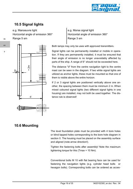
The distance "d" from the centre navigation light to the centre<br />
mast can be seen in the diagram. If two white <strong>signal</strong> lights are<br />
utilized as anchor lights, these must be mounted so that one of<br />
them is visible above the entire horizon.<br />
d<br />
If 2 or 3 <strong>signal</strong> lights are positioned vertically above one another,<br />
the spacing between them must be minimum 2 m. When<br />
mixed coloured <strong>signal</strong> lights (two different <strong>signal</strong> lights in one<br />
housing) are installed, may not both be used together. The distance<br />
rule is observed!<br />
<br />
10.6 Mounting<br />
The level foundation plate must be provided with 4 bore holes<br />
or blind tapped holes corresponding to the bore hole diagram in<br />
section 0. The housing must be placed on the assembly surface<br />
and aligned (note arrow direction!).<br />
Tighten the fastening bolts after assembly! Note the maximum<br />
tightening torque for this (Tmax = 10 Nm).<br />
<strong>Co</strong>nventional bolts M 10 with flat bearing face can be used for<br />
fastening the navigation lights (e.g. cylinder head bolts or<br />
hexagon bolts). <strong>Co</strong>rresponding bolts can be ordered as acces-<br />
Page 16 of 35 9420102300_en.doc Rev.: 04


