Specification sheet (English) - Trend
Specification sheet (English) - Trend Specification sheet (English) - Trend
IQ23x Data Sheet Integral nodes (continued) CNC2, PNC2, INC2, TMN (TMN board - circa 1999) 24 Vdc Power CNC2, PNC2 local network INC2 local network or internetwork segment A TMN local network or internetwork = * = ) % - 6 ' & CNC2, PNC2, TMN not used INC2 internetwork or internetwork segment B , AL ) RS232 CNC2 to device PNC2 to printer INC2 not normally used TMNE to modem , AL * @ A # $ Integral modem (TMNH only) earth tag PSTN (TMNH only) XNC220: This node replaces the XNC but is only available in a boxed form (NBOX/XNC220) and cannot be mounted in an IQ. ENC2: This node is used with the EMMPO2, but is only available in boxed form (NBOX/ENC2) and cannot be mounted in an IQ. Baud Rates: All the nodes are capable of being linked for 1k2, 4k8, 9k6, or 19k2 baud for both of the network connections (Lan A, Lan B); except for the LINC which can only be linked for 1k2, 9k6 or 19k2. The IQ23x is capable of all 4 baud rates. The INC2 is also capable of being linked for 38k4 baud on its internetwork or internetwork segment B port (Lan B). Display Panel The IQ23x can have an integral 2 line display panel either pre‐fitted, or post-fitted (by replacing the cover with COVER/ DP2/IQ23x). The display panel looks different to that of the IQ111 or 131, as the membrane has been through a layout change. However, although the arrow and letter keys are in different places, they have the same functionality. Note that an integral display panel fitted in an IQ111(+) or IQ131(+) may not be used with an IQ23x. An external 2 line display panel (e.g. HDP, FPK) could be directly fitted to an IQ111 (+),131 (+). The same display panel can be connected to an IQ23x, but it requires the internal fitting of KIT/2xx/RDS, the remote display panel support kit. Controller Baud Rates The controllers have different local supervisor port, and network baud rates. The network baud rate is set by a link; the supervisor baud rate is now fixed at 9k6 but was configurable by link on the earlier controllers. The IQ131 is unique in not having CNC functionality built in to its firmware so it needed a CNC to be fitted, and the network baud rate is set by a link on the CNC board. Controller Address The IQ111 controller address was set in configuration mode so it should be checked in configuration mode before replacement. The IQ131 address is set by DIL switches on its CNC. The Address is set by DIL switches on the controller board for IQ111+, 131+, and IQ23x. Firmware File compatibility: The IQ23x module suite has either the same or greater numbers of modules than the IQ111 (+), 131 (+). The IQ111 (+), 131 (+) strategy can be uploaded into a strategy file (.IQF) using Power Tool or WupDn. It can then be downloaded into the IQ23x. Special cables are required to connect to a PC for uploading from IQ111 (+), IQ131 (+). The IQ111, 131 requires CABLE/58-0750 (9 Way Female D type to 25 Way Male D type), and the IQ111+, 131+ require the additional adaptor CABLE/78-1172 (25 Way Female D type to 5 in line Stocko). Certain modifications are required for it to run correctly, and this can either be done in the controller using configuration mode (via PowerTool or WupDn), or the strategy file can be uploaded (as an .IQ2 file) into SET and the changes made there before downloading to the IQ23x. If strategy diagrams are required they can be loaded into SET from an earlier ACE or SET file, or can be laid out in SET from the strategy file (uploaded from the IQ23x after an .IQF download as either an .IQ2 or .SCN file). The standard IQ1xx to IQ2xx modifications are described in the IQ configuration Manual Addendum (TD200118). Bit 506,1: This bit is used to set Emulation for IQ1xx Universal Inputs. It applies in the case where an internal sensor module is used in internal digital mode. INTERNAL DIGITAL NODE Controller Supervisor Network IQ111 1k2 or 9k6 1k2, 4k8, 9k6, or 19k2 IQ131 1k2 or 9k6 via integral CNC board 1k2, 4k8, 9k6, or 19k2 IQ111+, IQ131+ 9k6 1k2, 9k6, 19k2 IQ23x 9k6 1k2, 4k8, 9k6, 19k2 INTERNAL DIGITAL MODE 5 1, digital node corresponding to input n In IQ1xx controllers, if a sensor (whose number is greater than the number of real input channels) is set to internal digital mode, it will take the value from an internal digital node and write it to its analogue node and digital input node. 10 IQ23x Series Controllers Data Sheet TA200538 Issue 2, 18-Jan-2012
Data Sheet IQ23x Firmware (continued) In IQ2xx controllers the sensor only writes to the analogue node (not to the digital input node) Bit 506,1 should be set to 1. If an IQ1xx strategy using the internal digital sensor output to an internal digital input node connection is downloaded to an IQ2xx setting the bit to zero restores IQ2xx mode. Sharing Labels: As explained in the IQ Configuration Manual (90-1533), the IQ111 (+), 131 (+) sensor and digital input modules share labels. The IQ23x has separate labels so that in a file transferred from IQ1xx to IQ2xx, the sensors will have the original labels, and the digital inputs will need their labels to be set up. IQ131 (+) Input Channels: The differences in the arrangement of input channels on the IQ131 (+) and IQ231 produce some upgrade problems. The IQ111 (+) upgrade doesn’t have similar problems as the controllers have the same numbers of input channels. Fast Sequencing of Digital Inputs: The fast sequencing on the IQ131+ was set up so that fast sequence input references I1 to I4 referred to input channels 17 to 20, and references I5 to I8 referred to input channels 5 to 8. (Note that all other references remained the same e.g. configuring module I1 set up internal digital input 1 for node 1,0 which corresponded to input channel 1). In the IQ23x, the fast digital input channel references I1 to I8 refer to input channels 1 to 8. When an IQ131+ file is transferred to the IQ23x, fast sequence I1 now refers to input channel 1. If fast sequencing was required on fast sequence inputs 1 to 4 it would require channel connections to be changed and the associated strategy to be transferred across the channels. IQ131 Internal Digitals: The IQ131 internal channels start at 17 whereas in the IQ23x, channels 17 to 20 are real. So if the IQ131 strategy used an internal digital in the range 17 to 20, it would get overridden by the real input in the IQ23x. If such internal digitals were used, they should be moved to a area of unused internals on the IQ23x (digital input 21 onwards). 13 ! 7 ELA HI= 1 FJI K 1JAH = I ! " # $ % & ' ! " # $ % & ' ! " 13 ! ) = C K A , EC EJ= 1 F KI J 7 ELA HI= 1 FJI K 1 F KI J 1JAH = I ! " # $ % & ' ! " # $ % & ' ! " 13 !! 7 ELA HI= 1 FJI K 1JAH = I ! " # $ % & ' ! " # $ % & ' ! " IQ23x Series Controllers Data Sheet TA200538 Issue 2, 18-Jan-201211
- Page 1 and 2: ) ,, 4- 5 5 * ) 7, " & $ ! $ " '
- Page 3 and 4: Data Sheet IQ23x Hardware (continue
- Page 5 and 6: Data Sheet IQ23x Compatibility Supe
- Page 7 and 8: Data Sheet IQ23x I/O Channels IQ Co
- Page 9: Data Sheet IQ23x Integral nodes (co
- Page 13 and 14: ) ,, 4- 5 5 * ) 7, " & $ ! $ " '
- Page 15 and 16: Data Sheet IQ23x Specification Elec
Data Sheet<br />
IQ23x<br />
Firmware (continued)<br />
In IQ2xx controllers the sensor only writes to the analogue<br />
node (not to the digital input node) Bit 506,1 should be set to 1.<br />
If an IQ1xx strategy using the internal digital sensor output to<br />
an internal digital input node connection is downloaded to an<br />
IQ2xx setting the bit to zero restores IQ2xx mode.<br />
Sharing Labels: As explained in the IQ Configuration Manual<br />
(90-1533), the IQ111 (+), 131 (+) sensor and digital input<br />
modules share labels. The IQ23x has separate labels so that<br />
in a file transferred from IQ1xx to IQ2xx, the sensors will have<br />
the original labels, and the digital inputs will need their labels<br />
to be set up.<br />
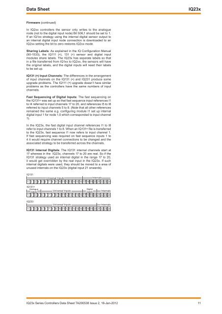
IQ131 (+) Input Channels: The differences in the arrangement<br />
of input channels on the IQ131 (+) and IQ231 produce some<br />
upgrade problems. The IQ111 (+) upgrade doesn’t have similar<br />
problems as the controllers have the same numbers of input<br />
channels.<br />
Fast Sequencing of Digital Inputs: The fast sequencing on<br />
the IQ131+ was set up so that fast sequence input references I1<br />
to I4 referred to input channels 17 to 20, and references I5 to I8<br />
referred to input channels 5 to 8. (Note that all other references<br />
remained the same e.g. configuring module I1 set up internal<br />
digital input 1 for node 1,0 which corresponded to input channel<br />
1).<br />
In the IQ23x, the fast digital input channel references I1 to I8<br />
refer to input channels 1 to 8. When an IQ131+ file is transferred<br />
to the IQ23x, fast sequence I1 now refers to input channel 1.<br />
If fast sequencing was required on fast sequence inputs 1 to<br />
4 it would require channel connections to be changed and the<br />
associated strategy to be transferred across the channels.<br />
IQ131 Internal Digitals: The IQ131 internal channels start at<br />
17 whereas in the IQ23x, channels 17 to 20 are real. So if the<br />
IQ131 strategy used an internal digital in the range 17 to 20,<br />
it would get overridden by the real input in the IQ23x. If such<br />
internal digitals were used, they should be moved to a area of<br />
unused internals on the IQ23x (digital input 21 onwards).<br />
13 !<br />
7 ELA HI= 1 FJI<br />
K<br />
1JAH = I<br />
! " # $ % & ' ! " # $ % & ' ! "<br />
13 ! <br />
) = C K A<br />
, EC EJ=<br />
1 F KI<br />
J<br />
7 ELA HI= 1 FJI<br />
K<br />
1 F KI<br />
J 1JAH = I<br />
! " # $ % & ' ! " # $ % & ' ! "<br />
13 !!<br />
7 ELA HI= 1 FJI<br />
K<br />
1JAH = I<br />
! " # $ % & ' ! " # $ % & ' ! "<br />
IQ23x Series Controllers Data Sheet TA200538 Issue 2, 18-Jan-201211


