Cooper B-Line Seismic Restraints - Dixie Construction Products
Cooper B-Line Seismic Restraints - Dixie Construction Products
Cooper B-Line Seismic Restraints - Dixie Construction Products

Create successful ePaper yourself
Turn your PDF publications into a flip-book with our unique Google optimized e-Paper software.
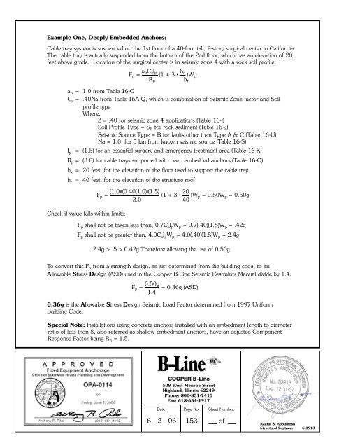
Example One, Deeply Embedded Anchors:<br />
Cable tray system is suspended on the 1st floor of a 40-foot tall, 2-story surgical center in California.<br />
The cable tray is actually suspended from the bottom of the 2nd floor, which has an elevation of 20<br />
feet above grade. Location of the surgical center is in seismic zone 4 with a rock soil profile.<br />
F p = a pC a I p<br />
(1 + 3 • hx )W p<br />
R p<br />
h r<br />
a p = 1.0 from Table 16-O<br />
C a = .40Na from Table 16A-Q, which is combination of <strong>Seismic</strong> Zone factor and Soil<br />
profile type<br />
Where,<br />
Z = .40 for seismic zone 4 applications (Table 16-I)<br />
Soil Profile Type = S B for rock sediment (Table 16-J)<br />
<strong>Seismic</strong> Source Type = B for faults other than Type A & C (Table 16-U)<br />
Na = 1.0, for 5 km from known seismic source (Table 16-S)<br />
I p<br />
= (1.5) for an essential surgery and emergency treatment area (Table 16-K)<br />
R p = (3.0) for cable trays supported with deep embedded anchors (Table 16-O)<br />
h x = 20 feet, for the elevation of the floor used to support the cable tray<br />
h r<br />
= 40 feet, for the elevation of the structure roof<br />
Check if value falls within limits:<br />
F p = (1.0)((0.40(1.0))(1.5) (1 + 3 • 20 )W p = 0.50W p = 0.50g<br />
3.0 40<br />
F p shall not be taken less than, 0.7C a I p W p = 0.7(.40)(1.5)W p = .42g<br />
F p shall not be greater than, 4.0C a I p W p = 4.0(.40)(1.5)W p = 2.4g<br />
2.4g > .5 > 0.42g Therefore allowing the use of 0.50g<br />
To convert this F p from a strength design, as just determined from the building code, to an<br />
Allowable Stress Design (ASD) used in the <strong>Cooper</strong> B-<strong>Line</strong> <strong>Seismic</strong> <strong>Restraints</strong> Manual divide by 1.4.<br />
F p = 0.50g = 0.36g (ASD)<br />
1.4<br />
0.36g is the Allowable Stress Design <strong>Seismic</strong> Load Factor determined from 1997 Uniform<br />
Building Code.<br />
Special Note: Installations using concrete anchors installed with an embedment length-to-diameter<br />
ratio of less than 8, also referred as shallow embedment anchors, have an adjusted Component<br />
Response Factor being R p = 1.5.<br />
COOPER B-<strong>Line</strong><br />
509 West Monroe Street<br />
Highland, Illinois 62249<br />
Phone: 800-851-7415<br />
Fax: 618-654-1917<br />
Date:<br />
Page No.<br />
Sheet Number:<br />
6 - 2 - 06<br />
153<br />
of<br />
Raafat S. Aboulhosn<br />
Structural Engineer S 3913