Cooper B-Line Seismic Restraints - Dixie Construction Products
Cooper B-Line Seismic Restraints - Dixie Construction Products Cooper B-Line Seismic Restraints - Dixie Construction Products
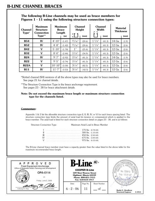
B-LINE CHANNEL BRACES The following B-Line channels may be used as brace members for Figures 1 - 11 using the following structure connection types: Maximum Maximum Channel Channel Material Channel Structure Brace Height Width Thickness Type* Connection Length Type** (m) (mm) (mm) (mm) B54 IV 4’-10” (1.47) 13/16” (20.6) 1 5 /8” (41.3) 14 Ga. (1.9) B52 IV 4’-8” (1.42) 13/16” (20.6) 1 5 /8” (41.3) 12 Ga. (2.6) B42 V 5’-10” (1.78) 1” (25.4) 1 5 /8” (41.3) 12 Ga. (2.6) B32 V 8’-0” (2.44) 1 3 /8” (34.9) 1 5 /8” (41.3) 12 Ga. (2.6) B24 IV 9’-7” (2.92) 1 5 /8” (41.3) 1 5 /8” (41.3) 14 Ga. (1.9) B22 V 9’-5” (2.74) 1 5 /8” (41.3) 1 5 /8” (41.3) 12 Ga. (2.6) B22A V 10’-10” (3.30) 3 1 /4” (82.5) 1 5 /8” (41.3) 12 Ga. (2.6) B11 IV 11’-7” (3.53) 3 1 /4” ( 82.5) 1 5 /8” (41.3) 12 Ga. (2.6) *Slotted channel (SH) versions of all the above types may also be used for brace members. See page 21 for channel details. **The Structure Connection Type is the brace anchorage requirement. See pages 23 - 38 for brace attachment details. Note: Do not exceed the maximum brace length or maximum structure connection type for the channels listed. Commentary: Appendix 1 & 2 list the allowable structure connection type (I, II, III, IV, or V) for each brace spacing listed. The structure connection type limits the amount of axial load (in tension or compression) which is applied to the brace member. The axial load is listed for each structure connection detail on pages 23 - 38, and is as follows: Structure Connection Type Maximum Axial Load in Brace Member I . . . . . . . . . . . . . . . . . . . . . . . . . . . . . . . . . . . . . . . 175 lbs. (0.78 kN) II . . . . . . . . . . . . . . . . . . . . . . . . . . . . . . . . . . . . . . 300 lbs. (1.33 kN) III . . . . . . . . . . . . . . . . . . . . . . . . . . . . . . . . . . . . . . 450 lbs. (2.00 kN) IV . . . . . . . . . . . . . . . . . . . . . . . . . . . . . . . . . . . . . . 675 lbs. (3.00 kN) V . . . . . . . . . . . . . . . . . . . . . . . . . . . . . . . . . . . . . . 975 lbs. (4.33 kN) The B-Line channel brace member must have a capacity greater than the value listed in the above table for the maximum recommended brace length. COOPER B-Line 509 West Monroe Street Highland, Illinois 62249 Phone: 800-851-7415 Fax: 618-654-1917 Date: Page No. Sheet Number: 6 - 2 - 06 11 of Raafat S. Aboulhosn Structural Engineer S 3913
SINGLE PIPE/CONDUIT BRACING Single Rod Hanger Pipe Bracing 1) Layout piping run and determine size and location of piping. 2) Select vertical supports (single rod pipe hangers). a) Select type of hanger dependent on type of pipe, thermal expansion and contraction, etc. b) Determine maximum spacing of hanger rods and minimum hanger rod diameter. (Appendix 1) c) Select hanger rod connection to the structure based on structure type, rod size and hanger rod load from Appendix 1. Refer to section on hanger rod attachment for details (pages 39 thru 56) d) Engineer of record for a site specific project shall verify that the structure can support the connection loads in addition to all other loads. 3) Select lateral bracing (transverse and longitudinal bracing). a) Select bracing details (transverse & longitudinal) from Figures 1 thru 8. b) Determine maximum spacing for transverse and longitudinal braces. (Appendix 1) c) Determine the type of structure connection required. (Appendix 1) Refer to section on structural attachments for connection details. d) Determine if rod stiffener is required. (pages 57 & 58) e) Engineer of record for a site specific project shall verify that the structure can support the connection loads. 4) Review the design and revise layout where loads exceed the limitations of the hanger ro d s , hangers or connection details. COOPER B-Line 509 West Monroe Street Highland, Illinois 62249 Phone: 800-851-7415 Fax: 618-654-1917 Date: Page No. Sheet Number: Raafat S. Aboulhosn Structural Engineer S 3913 6 - 2 - 06 12 of
- Page 1 and 2: SEISMIC RESTRAINTS Multi-Directiona
- Page 3 and 4: TABLE OF CONTENTS General Informati
- Page 5 and 6: GENERAL INFORMATION I p = Importanc
- Page 7 and 8: GENERAL INFORMATION Cable tray syst
- Page 9 and 10: GENERAL INFORMATION c) Check the re
- Page 11 and 12: GENERAL INFORMATION f) When a flexi
- Page 13: GENERAL NOTES FOR SEISMIC BRACING G
- Page 17 and 18: SINGLE PIPE BRACING PIPE CLAMP TRAN
- Page 19 and 20: CLEVIS HANGER TRANSVERSE BRACING (F
- Page 21 and 22: TRAPEZE BRACING TRAPEZE TRANSVERSE
- Page 23 and 24: TRAPEZE BRACING TRAPEZE TRANSVERSE
- Page 25 and 26: TRAPEZE BRACING Typical Trapeze ATR
- Page 27 and 28: STRUCTURAL ATTACHMENTS ‘T’ Conc
- Page 29 and 30: Concrete Attachments Detail 4 Metal
- Page 31 and 32: Concrete Attachments STRUCTURAL ATT
- Page 33 and 34: STRUCTURAL ATTACHMENTS Minimum dist
- Page 35 and 36: STRUCTURAL ATTACHMENTS Concrete Att
- Page 37 and 38: STRUCTURAL ATTACHMENTS Wood Beam At
- Page 39 and 40: STRUCTURAL ATTACHMENTS Wood Beam At
- Page 41 and 42: Structural Steel Detail 16 Case 1 C
- Page 43 and 44: Concrete Attachments To Slab HANGER
- Page 45 and 46: Concrete Attachments To Slab HANGER
- Page 47 and 48: Concrete Attachments To Slab HANGER
- Page 49 and 50: Concrete Attachments To Slab HANGER
- Page 51 and 52: Strut Attachments Typical All Threa
- Page 53 and 54: HANGER ROD ATTACHMENTS & APPROVED C
- Page 55 and 56: HANGER ROD ATTACHMENTS & APPROVED C
- Page 57 and 58: HANGER ROD ATTACHMENTS & APPROVED C
- Page 59 and 60: HANGER ROD SWIVEL ATTACHMENTS A 2 3
- Page 61 and 62: APPROVED COMPONENTS SC228 HANGER RO
- Page 63 and 64: APPROVED COMPONENTS NOTE: B633 can
B-LINE CHANNEL BRACES<br />
The following B-<strong>Line</strong> channels may be used as brace members for<br />
Figures 1 - 11 using the following structure connection types:<br />
Maximum Maximum Channel Channel<br />
Material<br />
Channel Structure Brace Height Width<br />
Thickness<br />
Type* Connection Length<br />
Type** (m) (mm) (mm) (mm)<br />
B54 IV 4’-10” (1.47) 13/16” (20.6) 1 5 /8” (41.3) 14 Ga. (1.9)<br />
B52 IV 4’-8” (1.42) 13/16” (20.6) 1 5 /8” (41.3) 12 Ga. (2.6)<br />
B42 V 5’-10” (1.78) 1” (25.4) 1 5 /8” (41.3) 12 Ga. (2.6)<br />
B32 V 8’-0” (2.44) 1 3 /8” (34.9) 1 5 /8” (41.3) 12 Ga. (2.6)<br />
B24 IV 9’-7” (2.92) 1 5 /8” (41.3) 1 5 /8” (41.3) 14 Ga. (1.9)<br />
B22 V 9’-5” (2.74) 1 5 /8” (41.3) 1 5 /8” (41.3) 12 Ga. (2.6)<br />
B22A V 10’-10” (3.30) 3 1 /4” (82.5) 1 5 /8” (41.3) 12 Ga. (2.6)<br />
B11 IV 11’-7” (3.53) 3 1 /4” ( 82.5) 1 5 /8” (41.3) 12 Ga. (2.6)<br />
*Slotted channel (SH) versions of all the above types may also be used for brace members.<br />
See page 21 for channel details.<br />
**The Structure Connection Type is the brace anchorage requirement.<br />
See pages 23 - 38 for brace attachment details.<br />
Note: Do not exceed the maximum brace length or maximum structure connection<br />
type for the channels listed.<br />
Commentary:<br />
Appendix 1 & 2 list the allowable structure connection type (I, II, III, IV, or V) for each brace spacing listed. The<br />
structure connection type limits the amount of axial load (in tension or compression) which is applied to the<br />
brace member. The axial load is listed for each structure connection detail on pages 23 - 38, and is as follows:<br />
Structure Connection Type<br />
Maximum Axial Load in Brace Member<br />
I . . . . . . . . . . . . . . . . . . . . . . . . . . . . . . . . . . . . . . . 175 lbs. (0.78 kN)<br />
II . . . . . . . . . . . . . . . . . . . . . . . . . . . . . . . . . . . . . . 300 lbs. (1.33 kN)<br />
III . . . . . . . . . . . . . . . . . . . . . . . . . . . . . . . . . . . . . . 450 lbs. (2.00 kN)<br />
IV . . . . . . . . . . . . . . . . . . . . . . . . . . . . . . . . . . . . . . 675 lbs. (3.00 kN)<br />
V . . . . . . . . . . . . . . . . . . . . . . . . . . . . . . . . . . . . . . 975 lbs. (4.33 kN)<br />
The B-<strong>Line</strong> channel brace member must have a capacity greater than the value listed in the above table for the<br />
maximum recommended brace length.<br />
COOPER B-<strong>Line</strong><br />
509 West Monroe Street<br />
Highland, Illinois 62249<br />
Phone: 800-851-7415<br />
Fax: 618-654-1917<br />
Date:<br />
Page No.<br />
Sheet Number:<br />
6 - 2 - 06<br />
11<br />
of<br />
Raafat S. Aboulhosn<br />
Structural Engineer S 3913


