Cooper B-Line Seismic Restraints - Dixie Construction Products
Cooper B-Line Seismic Restraints - Dixie Construction Products
Cooper B-Line Seismic Restraints - Dixie Construction Products

You also want an ePaper? Increase the reach of your titles
YUMPU automatically turns print PDFs into web optimized ePapers that Google loves.
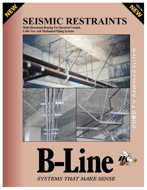
SEISMIC RESTRAINTS<br />
Multi-Directional Bracing For Electrical Conduit,<br />
Cable Tray And Mechanical Piping Systems<br />
SYSTEMS THAT MAKE SENSE
INTRODUCTION<br />
INTRODUCTION<br />
What is <strong>Seismic</strong> Bracing?<br />
<strong>Seismic</strong> forces are exerted on a building and its contents during an earthquake. These forces act<br />
horizontally upon the structure itself, as well as the piping, cable trays, ductwork, and other building<br />
systems within. Typical supports for piping, trays, and other equipment are designed for the gravity,<br />
or vertical, loads but do not take into account the horizontal loading caused by earthquakes. <strong>Seismic</strong><br />
restraints (i.e. braces) resist the horizontal forces and keep the systems in place and secure. The main<br />
purpose of seismic bracing is safety- to minimize the loss of life due to an earthquake.<br />
<strong>Seismic</strong> Bracing Requirements<br />
The rules and requirements for the seismic restraints are published in the model building codes: The<br />
Uniform Building Code (Inter national Conference of Building Officials), National Building Code<br />
(Building Officials and Code Administrators), Standard Building Code (Southern Building Code<br />
Congress International), and the International Building Code. Each code is similar in nature, and has a<br />
chapter on structural forces which defines the level of seismic force that must be used in the design of<br />
seismic restraints.<br />
The amount of seismic force (as determined by the building code) is given as a percent of the<br />
components’ weight, or g-force. If the horizontal force is determined to be 50 percent of the piping<br />
weight, for example, the seismic force is .5g.<br />
The seismic "g-value" can vary greatly depending on the nature of the project. Critical buildings in a<br />
high seismic zone have larger g-value requirements than warehouses in zone 1.<br />
Factors that govern the seismic g-values used for design:<br />
• <strong>Seismic</strong> Zone<br />
• Soil Type<br />
• Building Type<br />
• Distance from known faults<br />
• Elevation within building • Anchorage Type<br />
• System being braced<br />
The design professional should use these factors and the applicable building code requirements to<br />
determine the proper g-values to be used for the project.<br />
This manual has been developed under the requirements of the 2001 California Building Code,<br />
and contains seismic bracing details that can be used for seismic bracing projects up to 1.0g (ASD) or<br />
1.4g. The brace spacing charts, required details, and rod loads must be determined for the specific<br />
g-value for the project and shall be submitted to the engineer of record prior to construction. The<br />
determination of the seismic force level shall also be submitted to the engineer of record and to<br />
OSHPD for hospital projects in the state of California prior to construction. However, the seismic<br />
force level need not be submitted to the engineer of record or OSHPD if included in the original<br />
construction documents. This brochure contains charts for a variety of g values, however custom charts<br />
can be created to reflect different g-values as required for the project. Contact B-<strong>Line</strong> Engineering at<br />
618-654-2184 with your requirements.<br />
A copy of the complete <strong>Seismic</strong> <strong>Restraints</strong> Manual shall be on the jobsite for the duration of the<br />
project. Appropriate shop drawings signed/stamped by the architect or engineer of record must also<br />
be kept. OSHPD reserves the right to review these upon request.<br />
COOPER B-<strong>Line</strong><br />
509 West Monroe Street<br />
Highland, Illinois 62249<br />
Phone: 800-851-7415<br />
Fax: 618-654-1917<br />
Date:<br />
Page No.<br />
Sheet Number:<br />
6 - 2 - 06<br />
i<br />
of<br />
Raafat S. Aboulhosn<br />
Structural Engineer S 3913
TABLE OF CONTENTS<br />
General Information & Notes ................................ 1 - 11<br />
Single Pipe/Conduit Bracing Selection ....... 12 - 16<br />
Trapeze Bracing Selection .................................... 17 - 20<br />
Trapeze Members ........................................................ 21 - 22<br />
Structural Attachment Selection ................................. 23<br />
Concrete .......................................................................... 24 - 33<br />
Wood ................................................................................. 34 - 37<br />
Steel .............................................................................................. 38<br />
Hanger Rod Attachments &<br />
Approved Components ....................................................... 39<br />
Concrete .......................................................................... 40 - 46<br />
Wood ............................................................................................ 47<br />
Steel ................................................................................... 48 - 56<br />
Approved Components<br />
Rod Stiffeners ................................................................ 57 - 58<br />
Adjustable Hinge .......................................................... 59 - 60<br />
Hardware ......................................................................... 61 - 62<br />
Pipe Hangers/Clamps .............................................. 63 - 71<br />
Anchoring Components .......................................... 72 - 78<br />
Metric Conversion Charts .................................. 79<br />
<strong>Seismic</strong> Map ....................................................... 80<br />
Appendix 1<br />
Support Spacing Charts For<br />
Single Pipe/Conduit Applications (.15g, .30g,<br />
.45g, .50g, .75g and 1.00g) ................... 82 - 106<br />
Appendix 2<br />
Support Spacing Charts For<br />
Trapeze Applications (.15g, .30g, .45g, .50g,<br />
.75g and 1.00g) .................................. 108 - 145<br />
Appendix 3<br />
Proof Test Instructions For Concrete<br />
Anchors (IR26-6) ........................................... 146<br />
Appendix 4<br />
Calculating Your <strong>Seismic</strong> Force Level .... 147 - 155<br />
Appendix 5 (Beyond the scope of OSHPD)<br />
Additional Engineering Approvals ................... 156<br />
COOPER B-<strong>Line</strong><br />
509 West Monroe Street<br />
Highland, Illinois 62249<br />
Phone: 800-851-7415<br />
Fax: 618-654-1917<br />
Date:<br />
Page No.<br />
Sheet Number:<br />
Raafat S. Aboulhosn<br />
Structural Engineer S 3913<br />
6 - 2 - 06<br />
ii<br />
of
GENERAL INFORMATION<br />
B-LINE SEISMIC RESTRAINT SYSTEMS a re designed to resist seismic loading while minimizing<br />
installation time and providing superior perf o rmance. On the following pages, several methods of seismic<br />
bracing are illustrated. The choice of brace design should be governed by the system requirements and location<br />
of supports.<br />
Actual applications may vary and are not strictly limited to the combinations of fittings and supports shown.<br />
Any changes to the depicted designs should be in accordance with standard engineering practices and be<br />
approved by OSHPD (California Office of Statewide Health Planning & Development) if necessary.<br />
For additional information on hangers, channels, fittings, and hardware shown, see the latest B-<strong>Line</strong> Strut<br />
Systems Catalog or Pipe Hangers and Supports Catalog.<br />
<strong>Seismic</strong> restraints are designed to resist the horizontal seismic force in two primary directions: Transverse<br />
(perpendicular) and Longitudinal (parallel) to the run. The braces are attached to the building with a structure<br />
attachment (for concrete, steel, wood, etc.) of various anchor sizes. Typically, the stronger the structure<br />
attachment, the greater the brace spacing allowed.<br />
The following steps detail how to use the brochure:<br />
Step 1: Select the bracing details for single pipe hangers or trapeze supports.<br />
Step 2: Obtain required force level (%g) from applicable code for local jurisdiction or from the structural<br />
engineer of record.<br />
Example: 2001 California Building Code<br />
As defined in the 2001 California Building Code, Chapter 16A, Section 1632A, the seismic horizontal<br />
force, F p , may be calculated using the following formula:<br />
F p = a pC a I p<br />
(1 + 3 • hx )W p<br />
R p h r<br />
Where:<br />
Except that: F p shall not be less than 0.7 C a I p W p and need not be more than 4 C a I p W p .<br />
F p = <strong>Seismic</strong> Force Level<br />
a p<br />
= Amplification Factor (Table 16A-O)<br />
R p = Component Response Modification Factor (Table 16A-O)<br />
= 3.0 for electrical, mechanical and plumbing equipment and associated<br />
conduit, ductwork and piping utilizing deeply embedded anchors. (Table 16A-O)<br />
= 1.5 for installations using concrete anchors with an embedment-to-diameter<br />
ratio less than 8.<br />
i.e. a 1 /2" diameter concrete anchor with an embedment of less than 4" inches.<br />
COOPER B-<strong>Line</strong><br />
509 West Monroe Street<br />
Highland, Illinois 62249<br />
Phone: 800-851-7415<br />
Fax: 618-654-1917<br />
Date:<br />
Page No.<br />
Sheet Number:<br />
6 - 2 - 06<br />
1<br />
of<br />
Raafat S. Aboulhosn<br />
Structural Engineer S 3913
GENERAL INFORMATION<br />
I p<br />
= Importance Factor (Table 16A-K)<br />
= 1.5 for Essential facilities such as Hospitals, Fire Stations, Police Stations,<br />
Aviation Control Towers, etc. consult Table 16A-K in CBC for a detailed listing.<br />
= 1.0 for most other occupancies<br />
C a = <strong>Seismic</strong> Coefficient. This is a cumulation of several factors:<br />
Zone, Soil Properties, and distance from known fault.<br />
(Table 16A-I, Table 16A-J, Table 16A-Q, Table 16A-S, and Table 16A-U)<br />
h x<br />
= Element or component attachment elevation with respect to grade.<br />
Note: h x shall not be taken less than 0.0<br />
h r<br />
= Structure Roof Elevation with respect to grade.<br />
Special Note: This manual is based on allowable stress design (ASD), where as the seismic force level<br />
(%g or F p ) for non-structural components provided in building codes are based on strength design. For<br />
use in this manual, the seismic force levels (F p ) from the building code are converted to allowable stress<br />
design by dividing the result by 1.4.<br />
Example: If the building code yields, (F p ) = 1.4g, this value is converted to allowable stress design (ASD)<br />
as used in this catalog as follows: F p =1.4g/1.4=1.0 g<br />
Strength Design to Allowable Stress Design Conversions<br />
.21g from building code = .15g (ASD)<br />
.42g from building code = .30g (ASD)<br />
.63g from building code = .45g (ASD)<br />
.70g from building code = .50g (ASD)<br />
1.05g from building code = .75g (ASD)<br />
1.40g from building code = 1.00g (ASD)<br />
Example One, Deeply Embedded Anchors:<br />
Cable tray system is installed on the 1st floor of a 40-foot tall, 2-story surgical center in California. The<br />
cable tray is actually suspended from the bottom of the 2nd floor, which has an elevation of 20 feet<br />
above grade. Location of the surgical center is in seismic zone 4 with a rock soil profile.<br />
F p = a pC a I p<br />
(1 + 3 • hx )W p<br />
R p h r<br />
a p = 1.0 from Table 16A-O<br />
COOPER B-<strong>Line</strong><br />
509 West Monroe Street<br />
Highland, Illinois 62249<br />
Phone: 800-851-7415<br />
Fax: 618-654-1917<br />
Date:<br />
Page No.<br />
Sheet Number:<br />
Raafat S. Aboulhosn<br />
Structural Engineer S 3913<br />
6 - 2 - 06<br />
2<br />
of
GENERAL INFORMATION<br />
C a = .40Na from Table 16A-Q, which is a combination of Zone and Soil profile<br />
Zone 4 = .40, from Table 16A-I<br />
Rock Soil Profile = SB, from Table 16A-J<br />
<strong>Seismic</strong> Source Type = B, for faults other than Type A & C (Table 16A-U)<br />
Near Source Factor (Na) = 1.0, for 5 km from known seismic source (Table 16A-S)<br />
I p<br />
= 1.5 from Table 16A-K, Occupancies having surgery and emergency treatment areas.<br />
R p = 3.0 from Table 16A-O for deep embedded anchors<br />
h x = 20 feet<br />
h r<br />
= 40 feet<br />
F p = (1.0)(0.40(1.0))(1.5) (1 + 3 • 20 )W p = 0.50W p = 0.50g<br />
3.0 40<br />
Check if value falls within limits:<br />
F p shall not be taken less than, 0.7C a I p W p = 0.7(.40)(1.5)W p = .42g<br />
F p shall not be greater than, 4.0C a I p W p = 4.0(.40)(1.5)W p = 2.4g<br />
2.4g > .5 > 0.42g Therefore allowing the use of 0.50g<br />
To convert this F p from a strength design to an Allowable Stress Design (ASD) used in this catalog<br />
divide by 1.4.<br />
F p = 0.50g = 0.36g (ASD)<br />
1.4<br />
0.36g is the Allowable Stress Design <strong>Seismic</strong> Load Factor determined from the 2001 California<br />
Building Code.<br />
Special Note: A table for .36g (ASD) is not available in this catalog. When seismic force levels (%g or<br />
F p ) falls between catalog table values (i.e.: .15g, .30g, .45g, etc.) the seismic force level shall be<br />
rounded up to the next highest cataloged force level.<br />
Example: If F p = .36g (ASD), then use catalog tables for .45g (ASD).<br />
Example Two, Shallow Embedded Anchors:<br />
Special Note: Installations using concrete anchors installed with an embedment length-to-diameter<br />
ratio of less than 8, also referred to as shallow embedment anchors, have an adjusted Component<br />
Response Factor. The adjusted factor R p = 1.5.<br />
COOPER B-<strong>Line</strong><br />
509 West Monroe Street<br />
Highland, Illinois 62249<br />
Phone: 800-851-7415<br />
Fax: 618-654-1917<br />
Date:<br />
Page No.<br />
Sheet Number:<br />
6 - 2 - 06<br />
3<br />
of<br />
Raafat S. Aboulhosn<br />
Structural Engineer S 3913
GENERAL INFORMATION<br />
Cable tray system is installed on the 1st floor of a 40-foot tall, 2-story surgical center in California.<br />
The cable tray is actually suspended from the 2nd floor, which has an elevation of 20 feet above<br />
grade. Location of the surgical center is in seismic zone 4 with a rock soil profile, shallow<br />
embedment anchors are used for brace locations.<br />
a p<br />
= 1.0 from Table 16A-O<br />
F p = a pC a I p<br />
(1 + 3 hx • )W p<br />
R p h r<br />
C a = .40Na from Table 16A-Q, which is a combination of Zone and Soil profile<br />
Zone 4 = .40 from Table 16A-I<br />
Rock Soil Profile = SB from Table 16A-J<br />
<strong>Seismic</strong> Source Type = B for faults other than Type A & C (Table 16A-U)<br />
Near Source Factor (Na) = 1.0 for 5 km from known seismic source (Table 16A-S)<br />
I p<br />
= 1.5 from Table 16A-K, Occupancies having surgery and emergency treatment areas.<br />
R p = 1.5 adjusted for Shallow Embedment Anchors<br />
h x<br />
h r<br />
= 20 feet<br />
= 40 feet<br />
F p = (1.0)(0.40(1.0))(1.5) (1 + 3 • 20 )W p = 1.0W p = 1.0g<br />
1.5 40<br />
Check if value falls within limits:<br />
F p shall not be taken less than, 0.7C a I p W p = 0.7(.40)(1.5)W p = .42g<br />
F p shall not be greater than, 4.0C a I p W p = 4.0(.40)(1.5)W p = 2.4g<br />
2.4g > 1.0g > 0.42g Therefore allowing the use of 1.0g<br />
To convert this F p from a strength design to an Allowable Stress Design (ASD) used in this catalog<br />
divide by 1.4.<br />
F p = 1.0g = 0.71g (ASD)<br />
1.4<br />
0.71g is the Allowable Stress Design <strong>Seismic</strong> Load Factor determined from the 2001 California<br />
Building Code for shallow embedment anchors.<br />
Special Note: A table for .71g (ASD) is not available in this catalog. When seismic force levels (%g or<br />
F p ) falls between catalog table values (i.e.: .15g, .30g, .45g, etc.) the seismic force level shall be<br />
rounded up to the next highest cataloged force level.<br />
Example: If F p = .71g (ASD), then use catalog tables for .75g (ASD).<br />
Note: For other Code examples see Appendix 4<br />
COOPER B-<strong>Line</strong><br />
509 West Monroe Street<br />
Highland, Illinois 62249<br />
Phone: 800-851-7415<br />
Fax: 618-654-1917<br />
Date:<br />
Page No.<br />
Sheet Number:<br />
Raafat S. Aboulhosn<br />
Structural Engineer S 3913<br />
6 - 2 - 06<br />
4<br />
of
GENERAL INFORMATION<br />
Step 3:<br />
With required force level (%g), obtain the transverse and longitudinal brace spacing from<br />
Appendix 1 (single pipe) or Appendix 2 (trapeze hanger). The following notes shall be followed:<br />
a) B reak the length of pipe into separate straight runs, which are considered to be a single straight<br />
section between any bends in the pipe except where the bend is at an offset of less than the<br />
maximum offset length as defined below.<br />
Table 1 - Steel Pipe or Conduit<br />
Nominal Max. Offset Length (ft)<br />
Pipe<br />
Size 0.15g 0.3g 0.5g 0.75g 1.0g<br />
5 4 4 4 4 3<br />
6 6 6 6 6 5<br />
8 10 10 10 9 7<br />
10 10 10 10 10 9<br />
Table 2 - Copper Tubing<br />
Nominal Max. Offset Length (ft)<br />
Tubing<br />
Size 0.15g 0.3g 0.5g 0.75g 1.0g<br />
12 4 4 4 4 4<br />
Note: The tabulated values represent pipe and tubing with moment and shear transfering joints.<br />
T h e re f o re, for use of these tables pipes shall have welded, brazed, or UL Listed grooved joints. Pipe and<br />
tube sizes not listed above or joined as re q i u i red shall be limited to a maximum offset length of 2 ft.<br />
Maximum Offset Length (ft.)<br />
b) Brace each straight run in the transverse direction at both ends. Where several short runs occur,<br />
see note e) on the following page.<br />
Straight Run<br />
Transverse bracing at both ends of the pipe run<br />
COOPER B-<strong>Line</strong><br />
509 West Monroe Street<br />
Highland, Illinois 62249<br />
Phone: 800-851-7415<br />
Fax: 618-654-1917<br />
Date:<br />
Page No.<br />
Sheet Number:<br />
6 - 2 - 06<br />
5<br />
of<br />
Raafat S. Aboulhosn<br />
Structural Engineer S 3913
GENERAL INFORMATION<br />
c) Check the required spacing for transverse bracing (Appendixes 1 & 2) and compare it to the<br />
length of the straight run. If the length of the straight run is greater than the allowable distance<br />
for transverse bracing add transverse braces until the spacing does not exceed the allowable<br />
transverse brace distance.<br />
Straight Run<br />
Additional Transverse Braces<br />
d) Each straight run must have at least one longitudinal brace. Add longitudinal braces so that the<br />
spacing does not exceed the allowable longitudinal brace spacing in Appendixes 1 & 2.<br />
Straight Run<br />
Longitudinal Brace (Transverse brace<br />
for the adjacent run)<br />
Longitudinal Brace<br />
Longitudinal Brace<br />
(Transverse brace for<br />
the adjacent run)<br />
24” (610mm) Max.<br />
24” (610mm) Max.<br />
Note: A transverse brace may dually act as a longitudinal brace for an adjacent run when it is<br />
located within 24” of the adjacent straight run. However, Appendixes 1 & 2 shall be reviewed to<br />
use the stronger of the longitudinal or transverse brace re q u i rements, i.e. anchor and other<br />
component sizes.<br />
COOPER B-<strong>Line</strong><br />
509 West Monroe Street<br />
Highland, Illinois 62249<br />
Phone: 800-851-7415<br />
Fax: 618-654-1917<br />
Date:<br />
Page No.<br />
Sheet Number:<br />
Raafat S. Aboulhosn<br />
Structural Engineer S 3913<br />
6 - 2 - 06<br />
6<br />
of
GENERAL INFORMATION<br />
e) In many cases, several short runs occur one after the other. Based on previous requirements,<br />
each straight run requires a longitudinal brace when the adjacent short runs exceed the maximum<br />
offset length (ft.). When the adjacent short runs do not exceed the maximum offset length (ft.) the<br />
longitudinal braces can act as transverse braces as long as the allowable transverse brace spacing<br />
(Appendixes 1 & 2) is not exceeded.<br />
In the following layout, transverse braces are used as longitudinal braces when the straight runs<br />
are less than the maximum offset length (ft.). When a straight run exceeds the maximum offset<br />
length (ft.) additional braces are required.<br />
First Transverse Brace<br />
Second Transverse Brace<br />
Longitudinal<br />
brace<br />
Two braces may<br />
be required.<br />
Straight run<br />
exceeding the<br />
maximum offset<br />
length (ft.)<br />
Longitudinal<br />
brace<br />
Short run less<br />
than the maximum<br />
offset length (ft.)<br />
Multiple offsets can be treated as a single run when the<br />
total offset is less than the maximum offset length (ft.).<br />
Plan or Elevation<br />
COOPER B-<strong>Line</strong><br />
509 West Monroe Street<br />
Highland, Illinois 62249<br />
Phone: 800-851-7415<br />
Fax: 618-654-1917<br />
Date:<br />
Page No.<br />
Sheet Number:<br />
6 - 2 - 06<br />
7<br />
of<br />
Raafat S. Aboulhosn<br />
Structural Engineer S 3913
GENERAL INFORMATION<br />
f) When a flexible connection or swing joint is used, such as at a pipe drop to mechanical<br />
equipment, the pipe may cantilever at a length equal to or less than half the allowable transverse<br />
brace spacing (Appendixes 1 & 2). When greater than half the allowable transverse brace<br />
spacing, support to the floor is required as shown below.<br />
Straight Run<br />
Transverse brace at the<br />
end of horizontal run<br />
Requires a flexible connection or<br />
swing joint between equipment.<br />
Allowable Transverse Brace Spacing<br />
2<br />
Mechanical equipment.<br />
Floor<br />
If < 6 ft.<br />
Support to Floor<br />
Is Required.<br />
Step 4: Note the structure connection type (brace anchor requirements) from the Appendix,<br />
and select the brace anchorage detail to suit (pages 23 thru 38).<br />
Step 5: Note the hanger rod load from the Appendix, and select a rod attachment to structure<br />
to suit (pages 39 thru 56).<br />
Step 6: Check if rod stiffeners are required (pages 57 & 58) to prevent the hanger rod from<br />
buckling.<br />
<strong>Seismic</strong> restraints may typically be o m i t t e d for the following conditions where<br />
flexible connectors are provided between components and the associated<br />
ductwork, piping, and conduit:<br />
1. Fuel, medical gas, and vacuum piping less than 1 inch (25 mm) inside diameter.<br />
2. All other piping less than 2 1 /2 inches (64 mm) diameter, or:<br />
• All piping suspended by individual hangers 12 inches (305 mm) or less in length from the top<br />
of the pipe to the bottom of the structural support for the hanger<br />
• All electrical conduit less than 2 1 /2 inches (64 mm) trade size<br />
3. All rectangular air-handling ducts less than 6 ft 2 (0.56 m 2 ) in cross sectional area or:<br />
• All round air-handling ducts less than 28 inches (711 mm) in diameter<br />
• All ducts suspended by hangers 12 inches (305 mm) or less from the top of the duct to the<br />
bottom of the structural support for the hanger; where the hangers are detailed to avoid<br />
bending of the hangers and their connections. (To eliminate bending moment, flexible<br />
connections may be used. See B752 on page 49 or B446 & B446C on page 56)<br />
Where lateral restraints are omitted, the piping, ducts, or conduit shall be installed such that lateral<br />
motion of the piping, duct, or conduit will not cause damaging impact with other systems or<br />
structural members, or loss of vertical support.<br />
NOTE: Reference building code enforced by local authority with jurisdiction for specific<br />
requirements, and verify all omissions or exemptions with structural engineer of record.<br />
COOPER B-<strong>Line</strong><br />
509 West Monroe Street<br />
Highland, Illinois 62249<br />
Phone: 800-851-7415<br />
Fax: 618-654-1917<br />
Date:<br />
Page No.<br />
Sheet Number:<br />
Raafat S. Aboulhosn<br />
Structural Engineer S 3913<br />
6 - 2 - 06<br />
8<br />
of
GENERAL NOTES FOR SEISMIC BRACING<br />
GENERAL NOTES FOR SEISMIC BRACING<br />
A) The seismic restraint assemblies shown in this pre-approval document are designed to resist<br />
vertical loading simultaneously with seismic loading (transverse & longitudinal loading). Design<br />
recommendations shown are for single standard weight steel pipes filled with water. Contents<br />
other than water shall be evaluated by the user. Pipes of other approved materials shall be<br />
supported in accordance with their approved installation standards. Details not shown in this<br />
pre-approval shall be submitted to OSHPD for approval before installation if necessary.<br />
B) This bracing system is limited to the pipe sizes and support details shown. Special<br />
consideration must be given for pipe material and connections, insulation, thermal movement,<br />
vibration, and building seismic joints.<br />
C) Transverse and longitudinal braces shall be no more than 45° above or below the centerline of<br />
the pipe, duct, or tray.<br />
D) All channel and pipe clamp nuts and bolts shall be tightened to the following torques:<br />
1/4"-20 to 6 ft.-lbs. (8 N•m)<br />
3/8"-16 to 19 ft.-lbs. (26 N•m)<br />
1/2"-13 to 50 ft.-lbs. (68 N•m)<br />
5/8"-11 to 65 ft.-lbs. (88 N•m)<br />
3/4"-10 to 75 ft.-lbs. (101 N•m)<br />
E) The transverse and longitudinal bracing spacing listed in Appendix 1 & 2 is based on ductile<br />
piping (steel, copper, etc.) with ductile connections (welded, brazed, etc.) and has the following<br />
limitations:<br />
1) Transverse bracing shall not exceed 40’-0” (12.2 m).<br />
Longitudinal bracing shall not exceed 80’-0” (24.4 m).<br />
2) Fuel piping shall have transverse bracing 20'-0" (6.1 m) o.c. maximum and<br />
longitudinal bracing 40'-0" (12.2 m) o.c. maximum.<br />
3) Non-ductile piping, and piping with non-ductile connections shall have transverse<br />
bracing 20'-0" (6.1 m) o.c. maximum and longitudinal bracing 40'-0" (12.2 m) o.c.<br />
maximum or 1 /2 of the calculated brace spacing indicated in Appendix 1 or 2,<br />
whichever is more restrictive.<br />
F) Transverse bracing for one pipe section may also act as longitudinal bracing for the pipe<br />
section connected to it, if the bracing is installed within 24 inches (609 mm) of the elbow or tee<br />
of similar size. Figures 2 and 4 do not serve as adequate longitudinal braces.<br />
COOPER B-<strong>Line</strong><br />
509 West Monroe Street<br />
Highland, Illinois 62249<br />
Phone: 800-851-7415<br />
Fax: 618-654-1917<br />
Date:<br />
Page No.<br />
Sheet Number:<br />
6 - 2 - 06<br />
9<br />
of<br />
Raafat S. Aboulhosn<br />
Structural Engineer S 3913
GENERAL NOTES FOR SEISMIC BRACING<br />
G) Branch lines of a smaller diameter shall not be used to brace main lines.<br />
H) Where rod stiffeners are required a minimum of two hanger rod stiffener assemblies shall be<br />
installed. (Part number SC-228 or SC-UB)<br />
I) It is important to check anchorage details against the applicable building code requirements.<br />
<strong>Seismic</strong> design forces may increase substantially when anchors are considered “shallow”<br />
(embedded less than 8 times the anchor diameter).<br />
J) When bracing trapeze type hangers, the bracing shall be attached directly to the trapeze hanger<br />
assembly and piping secured to the trapeze assembly with pipe straps.<br />
K) A rigid piping system shall not be braced to diff e rent parts of a building that may re s p o n d<br />
differently during an earthquake. Example: Solid concrete wall and a roof (metal deck filled with<br />
lightweight concrete). Special care should be taken to avoid bracing rigid pipe on both sides of<br />
a building seismic joint without allowing for pipe and building movement.<br />
L) The pre-approval document is based on British Units (Inches & Pounds) and values noted in<br />
parenthesis (Metric or S.I. Units) are equivalent values. In case of conflicts, British Units will be<br />
the standards for evaluating the proper application of pre-approvals.<br />
M) The designer of the structure shall determine the adequacy of the support structure to carry the<br />
load of the piping and equipment. Engineer of record for a site specific project shall verify that<br />
the structure can support the connection loads of the hanger rod and the bracing attachments<br />
in addition to all other loads. This pre-approval document is not intended for the seismic design<br />
of the piping itself. The dynamic properties of the building structure and piping should be<br />
considered when selecting the type of piping to be installed.<br />
N) <strong>Seismic</strong> bracing shall not limit the expansion and contraction of the piping system. Always<br />
consider thermal movements when selecting brace locations and materials. The design for<br />
thermal movements is beyond the scope of OSHPD pre-approval.<br />
P) No portion of this pre-approval shall be taken out of context and used in other systems,<br />
design or purpose.<br />
Q) On transverse bracing, the pipe insulation material may be part of the brace assembly (i.e) in<br />
the load path. In this case the insulating material shall be capable of withstanding the lateral<br />
forces without damage and shall include a pipe shield for hangers or a pipe saddle for rollers.<br />
For longitudinal bracing, clamping must be applied directly to the pipe with any insulation<br />
being installed directly over the hanger and brace assembly. In these applications the<br />
mechanical engineer of record shall be contacted for insulating recommendations.<br />
COOPER B-<strong>Line</strong><br />
509 West Monroe Street<br />
Highland, Illinois 62249<br />
Phone: 800-851-7415<br />
Fax: 618-654-1917<br />
Date:<br />
Page No.<br />
Sheet Number:<br />
Raafat S. Aboulhosn<br />
Structural Engineer S 3913<br />
6 - 2 - 06<br />
10<br />
of
B-LINE CHANNEL BRACES<br />
The following B-<strong>Line</strong> channels may be used as brace members for<br />
Figures 1 - 11 using the following structure connection types:<br />
Maximum Maximum Channel Channel<br />
Material<br />
Channel Structure Brace Height Width<br />
Thickness<br />
Type* Connection Length<br />
Type** (m) (mm) (mm) (mm)<br />
B54 IV 4’-10” (1.47) 13/16” (20.6) 1 5 /8” (41.3) 14 Ga. (1.9)<br />
B52 IV 4’-8” (1.42) 13/16” (20.6) 1 5 /8” (41.3) 12 Ga. (2.6)<br />
B42 V 5’-10” (1.78) 1” (25.4) 1 5 /8” (41.3) 12 Ga. (2.6)<br />
B32 V 8’-0” (2.44) 1 3 /8” (34.9) 1 5 /8” (41.3) 12 Ga. (2.6)<br />
B24 IV 9’-7” (2.92) 1 5 /8” (41.3) 1 5 /8” (41.3) 14 Ga. (1.9)<br />
B22 V 9’-5” (2.74) 1 5 /8” (41.3) 1 5 /8” (41.3) 12 Ga. (2.6)<br />
B22A V 10’-10” (3.30) 3 1 /4” (82.5) 1 5 /8” (41.3) 12 Ga. (2.6)<br />
B11 IV 11’-7” (3.53) 3 1 /4” ( 82.5) 1 5 /8” (41.3) 12 Ga. (2.6)<br />
*Slotted channel (SH) versions of all the above types may also be used for brace members.<br />
See page 21 for channel details.<br />
**The Structure Connection Type is the brace anchorage requirement.<br />
See pages 23 - 38 for brace attachment details.<br />
Note: Do not exceed the maximum brace length or maximum structure connection<br />
type for the channels listed.<br />
Commentary:<br />
Appendix 1 & 2 list the allowable structure connection type (I, II, III, IV, or V) for each brace spacing listed. The<br />
structure connection type limits the amount of axial load (in tension or compression) which is applied to the<br />
brace member. The axial load is listed for each structure connection detail on pages 23 - 38, and is as follows:<br />
Structure Connection Type<br />
Maximum Axial Load in Brace Member<br />
I . . . . . . . . . . . . . . . . . . . . . . . . . . . . . . . . . . . . . . . 175 lbs. (0.78 kN)<br />
II . . . . . . . . . . . . . . . . . . . . . . . . . . . . . . . . . . . . . . 300 lbs. (1.33 kN)<br />
III . . . . . . . . . . . . . . . . . . . . . . . . . . . . . . . . . . . . . . 450 lbs. (2.00 kN)<br />
IV . . . . . . . . . . . . . . . . . . . . . . . . . . . . . . . . . . . . . . 675 lbs. (3.00 kN)<br />
V . . . . . . . . . . . . . . . . . . . . . . . . . . . . . . . . . . . . . . 975 lbs. (4.33 kN)<br />
The B-<strong>Line</strong> channel brace member must have a capacity greater than the value listed in the above table for the<br />
maximum recommended brace length.<br />
COOPER B-<strong>Line</strong><br />
509 West Monroe Street<br />
Highland, Illinois 62249<br />
Phone: 800-851-7415<br />
Fax: 618-654-1917<br />
Date:<br />
Page No.<br />
Sheet Number:<br />
6 - 2 - 06<br />
11<br />
of<br />
Raafat S. Aboulhosn<br />
Structural Engineer S 3913
SINGLE PIPE/CONDUIT BRACING<br />
Single Rod Hanger Pipe Bracing<br />
1) Layout piping run and determine size and location of piping.<br />
2) Select vertical supports (single rod pipe hangers).<br />
a) Select type of hanger dependent on type of pipe, thermal expansion and contraction, etc.<br />
b) Determine maximum spacing of hanger rods and minimum hanger rod diameter.<br />
(Appendix 1)<br />
c) Select hanger rod connection to the structure based on structure type, rod size and hanger<br />
rod load from Appendix 1. Refer to section on hanger rod attachment for<br />
details (pages 39 thru 56)<br />
d) Engineer of record for a site specific project shall verify that the structure can support<br />
the connection loads in addition to all other loads.<br />
3) Select lateral bracing (transverse and longitudinal bracing).<br />
a) Select bracing details (transverse & longitudinal) from Figures 1 thru 8.<br />
b) Determine maximum spacing for transverse and longitudinal braces. (Appendix 1)<br />
c) Determine the type of structure connection required. (Appendix 1)<br />
Refer to section on structural attachments for connection details.<br />
d) Determine if rod stiffener is required. (pages 57 & 58)<br />
e) Engineer of record for a site specific project shall verify that the structure can support<br />
the connection loads.<br />
4) Review the design and revise layout where loads exceed the limitations of the hanger ro d s ,<br />
hangers or connection details.<br />
COOPER B-<strong>Line</strong><br />
509 West Monroe Street<br />
Highland, Illinois 62249<br />
Phone: 800-851-7415<br />
Fax: 618-654-1917<br />
Date:<br />
Page No.<br />
Sheet Number:<br />
Raafat S. Aboulhosn<br />
Structural Engineer S 3913<br />
6 - 2 - 06<br />
12<br />
of
SINGLE PIPE BRACING<br />
CLEVIS HANGER TRANSVERSE BRACING (Figure 1)<br />
ATR<br />
All Threaded Rod<br />
(See Page 57 for<br />
minimum diameter)<br />
Rod Stiffener<br />
(See Pages 57 & 58)<br />
1<br />
1 (Min.)<br />
B335-2-Bolt Size<br />
Adjustable Hinge<br />
(See Page 59)<br />
B3100PS Pipe Sleeve<br />
B-<strong>Line</strong> Channel<br />
Transverse Brace<br />
(See page 11)<br />
B3100 Series Clevis Hanger<br />
(See Page 63)<br />
Adjustable Pipe<br />
Pipe Size Clevis Hanger Hinge Sleeve<br />
in. (mm) Part No. Part No. Part No.*<br />
1/2" (15) B3100- 1 /2 N/A N/A<br />
3/4" (20) B3100- 3 /4 N/A N/A<br />
1" (25) B3100-1 B335-2- 3 /8 B3100PS-1<br />
1 1 /4" (32) B3100-1 1 /4 B335-2- 3 /8 B3100PS-1 1 /4<br />
1 1 /2" (40) B3100-1 1 /2 B335-2- 3 /8 B3100PS-1 1 /2<br />
2" (50) B3100-2 B335-2- 3 /8 B3100PS-2<br />
2 1 /2" (65) B3100-2 1 /2 B335-2- 3 /8 B3100PS-2 1 /2<br />
3" (80) B3100-3 B335-2- 3 /8 B3100PS-3<br />
3 1 /2" (90) B3100-3 1 /2 B335-2- 3 /8 B3100PS-3 1 /2<br />
4" (100) B3100-4 B335-2- 3 /8 B3100PS-4<br />
5" (125) B3100-5 B335-2- 1 /2 B3100PS-5<br />
6" (150) B3100-6 B335-2- 1 /2 B3100PS-6<br />
8" (200) B3100-8 B335-2- 5 /8 B3100PS-8<br />
10" (250) B3100-10 B335-2- 3 /4 B3100PS-10<br />
12" (300) B3100-12 B335-2- 3 /4 B3100PS-12<br />
* Not included when ordering standard B3100 Series Clevis Hanger.<br />
Notes:<br />
Pipe sleeve required over cross bolt of Clevis Hanger when using the brace connection shown above (Figure 1).<br />
Pipe sleeve is not required when clevis hanger is used in conjunction with the bracing shown in Figure 6 - page 15.<br />
Refer to Note Q) on page 10 for installations requiring insulated pipe.<br />
"J" HANGER TRANSVERSE BRACING (Figure 2)<br />
Rod Stiffener<br />
May Be Required<br />
(See Pages 57 & 58)<br />
ATR<br />
All Threaded Rod<br />
(See Page 57 for<br />
minimum diameter)<br />
1<br />
1 Min.<br />
B-<strong>Line</strong> Channel<br />
Transverse Brace<br />
(See page 11)<br />
B335-2-Bolt Size<br />
Adjustable Hinge<br />
(See Page 59)<br />
B3690 Series<br />
'J' Hanger<br />
(See Page 64)<br />
Adjustable<br />
Pipe Size "J" Hanger Hinge<br />
in. (mm) Part No. Part No.<br />
1/2" (15) B3690- 1 /2 N/A<br />
3/4" (20) B3690- 3 /4 N/A<br />
1" (25) B3690-1 B335-2- 3 /8<br />
1 1 /4" (32) B3690-1 1 /4 B335-2- 3 /8<br />
1 1 /2" (40) B3690-1 1 /2 B335-2- 3 /8<br />
2" (50) B3690-2 B335-2- 3 /8<br />
2 1 /2" (65) B3690-2 1 /2 B335-2- 1 /2<br />
3" (80) B3690-3 B335-2- 1 /2<br />
3 1 /2" (90) B3690-3 1 /2 B335-2- 1 /2<br />
4" (100) B3690-4 B335-2- 1 /2<br />
5" (125) B3690-5 B335-2- 1 /2<br />
6" (150) B3690-6 B335-2- 1 /2<br />
8" (200) B3690-8 B335-2- 1 /2<br />
Note:<br />
Refer to Note Q) on page 10 for installations requiring insulated pipe.<br />
COOPER B-<strong>Line</strong><br />
509 West Monroe Street<br />
Highland, Illinois 62249<br />
Phone: 800-851-7415<br />
Fax: 618-654-1917<br />
Date:<br />
Page No.<br />
Sheet Number:<br />
6 - 2 - 06<br />
13<br />
of<br />
Raafat S. Aboulhosn<br />
Structural Engineer S 3913
SINGLE PIPE BRACING<br />
PIPE CLAMP TRANSVERSE BRACING (Figure 3)<br />
ATR<br />
All Threaded Rod<br />
(See Page 57)<br />
Rod Stiffener<br />
May Be Required<br />
(See Pages 57 & 58)<br />
1 (Min.)<br />
Adjustable<br />
Pipe Size Pipe Clamp * Hinge<br />
in. (mm) Part No. Part No.<br />
B-<strong>Line</strong> Channel<br />
Transverse Brace<br />
(See page 11)<br />
1<br />
B3200 Series<br />
Weldless Eye Nut<br />
1 1 /2" (40) B3144-1 1 /2 B335-2- 1 /2<br />
2" (50) B3144-2 B335-2- 1 /2<br />
2 1 /2" (65) B3144-2 1 /2 B335-2- 1 /2<br />
3" (80) B3144-3 B335-2- 1 /2<br />
4" (100) B3144-4 B335-2- 5 /8<br />
B335-2-Bolt Size<br />
Adjustable Hinge<br />
(See Page 59)<br />
5" (125) B3144-5 B335-2- 5 /8<br />
6" (150) B3144-6 B335-2- 3 /4<br />
8" (200) B3144-8 B335-2- 3 /4<br />
10" (250) B3144-10 B335-2- 3 /4<br />
12" (300) B3144-12 B335-2- 3 /4<br />
B3144 Series<br />
Double Bolt Pipe Clamp<br />
(See Page 65)<br />
* See note D) on page 9 for clamp torque values. Note: Refer to Note Q) on page 10 for installations requiring insulated pipe.<br />
PIPE ROLLER TRANSVERSE BRACING (Figure 4)<br />
ATR<br />
All Threaded Rod<br />
(See Page 57 for<br />
minimum diameter)<br />
Rod Stiffener<br />
(See Pages 57 & 58)<br />
Adjustable<br />
Pipe Size Pipe Roller Hinge<br />
in. (mm) Part No. Part No.<br />
1<br />
1 (Min.)<br />
B-<strong>Line</strong> Channel<br />
Transverse Brace<br />
(See page 11)<br />
2 1 /2" (65) B3110-2 1 /2 B335-2- 1 /2<br />
3" (80) B3110-3 B335-2- 1 /2<br />
3 1 /2" (90) B3110-2 1 /2 B335-2- 1 /2<br />
4" (100) B3110-4 B335-2- 1 /2<br />
5" (125) B3110-5 B335-2- 5 /8<br />
6" (150) B3110-6 B335-2- 3 /4<br />
B335-2-Bolt Size<br />
Adjustable Hinge<br />
(See Page 59)<br />
B3110 Series<br />
Adjustable Steel Yoke Pipe Roll<br />
(See Page 66)<br />
Note:<br />
Refer to Note Q) on page 10 for installations requiring insulated pipe.<br />
COOPER B-<strong>Line</strong><br />
509 West Monroe Street<br />
Highland, Illinois 62249<br />
Phone: 800-851-7415<br />
Fax: 618-654-1917<br />
Date:<br />
Page No.<br />
Sheet Number:<br />
Raafat S. Aboulhosn<br />
Structural Engineer S 3913<br />
6 - 2 - 06<br />
14<br />
of
SINGLE PIPE BRACING<br />
TRANSVERSE BRACING (Figure 5)<br />
B2400 Series<br />
Pipe Strap<br />
(See Page 71)<br />
1<br />
1 (Min.)<br />
3” min.<br />
(76mm)<br />
B-<strong>Line</strong> Channel<br />
Transverse Brace<br />
(See page 11)<br />
Channel Nuts & Bolts Not Included (See Pages 61 & 62)<br />
Notes: Install brace within 4" (101mm) of hanger. (Hanger not shown for clarity. See Figure 6 below)<br />
Refer to Note Q) on page 10 for installations requiring insulated pipe<br />
LONGITUDINAL BRACING (Figure 6)<br />
Rod Stiffener May Be Required<br />
(See Pages 63 & 64)<br />
B335V-Bolt Size<br />
Adjustable Half Hinge<br />
(See Page 59)<br />
Pipe Adjustable Riser Adjustable<br />
Pipe Size Clamp* Half Hinge Clamp * Half Hinge<br />
in. (mm) Part No. Part No. Part No. Part No.<br />
Pipe<br />
Hanger<br />
or<br />
Support<br />
4” max.<br />
(101mm)<br />
B-<strong>Line</strong> Channel<br />
Longitudinal Brace<br />
(See page 11)<br />
B3140 Pipe Clamp<br />
or B3373 Riser Clamp<br />
Series<br />
(See Pages 67 & 69)<br />
1" (25) B3140-1 B335V- 1 /2 B3373-1 B335V- 1 /2<br />
1 1 /4" (32) B3140-1 1 /4 B335V- 1 /2 B3373-1 1 /4 B335V- 1 /2<br />
1 1 /2" (40) B3140-1 1 /2 B335V- 1 /2 B3373-1 1 /2 B335V- 1 /2<br />
2" (50) B3140-2 B335V- 1 /2 B3373-2 B335V- 1 /2<br />
2 1 /2" (65) B3140-2 1 /2 B335V- 1 /2 B3373-2 1 /2 B335V- 1 /2<br />
3" (80) B3140-3 B335V- 1 /2 B3373-3 B335V- 1 /2<br />
3 1 /2" (90) B3140-3 1 /2 B335V- 1 /2 B3373-3 1 /2 B335V- 1 /2<br />
4" (100) B3140-4 B335V- 5 /8 B3373-4 B335V- 1 /2<br />
5" (125) B3140-5 B335V- 5 /8 B3373-5 B335V- 1 /2<br />
6" (150) B3140-6 B335V- 3 /4 B3373-6 B335V- 1 /2<br />
8" (200) B3140-8 B335V- 3 /4 B3373-8 B335V- 5 /8<br />
10" (250) -- -- B3373-10 B335V- 5 /8<br />
12" (300) -- -- B3373-12 B335V- 5 /8<br />
* See note D) on page 9 for clamp torque values.<br />
Notes: Install brace within 4" (101mm) of hanger.<br />
Refer to Note Q) on page 10 for installations requiring insulated pipe.<br />
COOPER B-<strong>Line</strong><br />
509 West Monroe Street<br />
Highland, Illinois 62249<br />
Phone: 800-851-7415<br />
Fax: 618-654-1917<br />
Date:<br />
Page No.<br />
Sheet Number:<br />
6 - 2 - 06<br />
15<br />
of<br />
Raafat S. Aboulhosn<br />
Structural Engineer S 3913
CLEVIS HANGER TRANSVERSE BRACING (Figure 7)<br />
SINGLE PIPE BRACING - COPPER TUBING<br />
ATR<br />
All Threaded Rod<br />
(See Page 57 for<br />
minimum diameter)<br />
Rod Stiffener<br />
(See Pages 57 & 58)<br />
1<br />
1 (Min.)<br />
B-<strong>Line</strong> Channel<br />
Transverse Brace<br />
(See page 11)<br />
B335-2-Bolt Size Adjustable Hinge<br />
(See Page 59)<br />
B3104CTPS Pipe Sleeve<br />
B3104CT Series Clevis Hanger<br />
(See Page 68)<br />
Copper Adjustable Pipe<br />
Tubing Size Clevis Hanger Hinge Sleeve<br />
in. (mm) Part No. Part No. Part No.*<br />
1/2" (15) B3104CT- 1 /2 N/A N/A<br />
3/4" (20) B3104CT- 3 /4 N/A N/A<br />
1" (25) B3104CT-1 B335-2- 3 /8 B3104CTPS-1<br />
1 1 /4" (32) B3104CT-1 1 /4 B335-2- 3 /8 B3104CTPS-1 1 /4<br />
1 1 /2" (40) B3104CT-1 1 /2 B335-2- 3 /8 B3104CTPS-1 1 /2<br />
2" (50) B3104CT-2 B335-2- 3 /8 B3104CTPS-2<br />
2 1 /2" (65) B3104CT-2 1 /2 B335-2- 3 /8 B3104CTPS-2 1 /2<br />
3" (80) B3104CT-3 B335-2- 3 /8 B3104CTPS-3<br />
3 1 /2" (90) B3104CT-3 1 /2 B335-2- 3 /8 B3104CTPS-3 1 /2<br />
4" (100) B3104CT-4 B335-2- 3 /8 B3104CTPS-4<br />
* Not included when ordering standard B3104CT Series Clevis Hanger.<br />
Notes:<br />
Pipe sleeve required over cross bolt of Clevis Hanger when using the brace connection shown above (Figure 7).<br />
Refer to Note Q) on page 10 for installations requiring insulated pipe.<br />
LONGITUDINAL BRACING (Figure 8)<br />
Rod Stiffener May Be Required<br />
(See Pages 57 & 58)<br />
B335V-Bolt Size<br />
Adjustable Half Hinge<br />
(See Page 59)<br />
Copper Riser Adjustable<br />
Tubing Size Clamp * Half Hinge<br />
in. (mm) Part No. Part No.<br />
B-<strong>Line</strong> Channel<br />
Longitudinal Brace<br />
(See page 11)<br />
1" (25) B3373CT-1 B335V- 1 /2<br />
1 1 /4" (32) B3373CT-1 1 /4 B335V- 1 /2<br />
1 1 /2" (40) B3373CT-1 1 /2 B335V- 1 /2<br />
2" (50) B3373CT-2 B335V- 1 /2<br />
2 1 /2" (65) B3373CT-2 1 /2 B335V- 1 /2<br />
3" (80) B3373CT-3 B335V- 1 /2<br />
3 1 /2" (90) B3373CT-3 1 /2 B335V- 1 /2<br />
4" (100) B3373CT-4 B335V- 1 /2<br />
Pipe Hanger<br />
or Support<br />
4” max.<br />
(101mm)<br />
B3373CT<br />
Riser Clamp Series<br />
(See Page 69)<br />
* See note D) on page 9 for clamp torque values.<br />
Note: Install brace within 4" (101mm) of hanger.<br />
Refer to Note Q) on page 10 for installations requiring insulated pipe.<br />
COOPER B-<strong>Line</strong><br />
509 West Monroe Street<br />
Highland, Illinois 62249<br />
Phone: 800-851-7415<br />
Fax: 618-654-1917<br />
Date:<br />
Page No.<br />
Sheet Number:<br />
Raafat S. Aboulhosn<br />
Structural Engineer S 3913<br />
6 - 2 - 06<br />
16<br />
of
TRAPEZE BRACING<br />
Trapeze Assembly Bracing<br />
1). Layout piping and/or conduit runs and determine number, size and location of items to be supported by<br />
the trapeze<br />
2). Determine trapeze support spacing (L T ). This is usually determined by the maximum support spacing of<br />
the smallest pipe or conduit on the trapeze.<br />
3). Select trapeze supports.<br />
a). Determine the total vertical load (T L ) for each trapeze.<br />
T L = L T x W T<br />
T L = Total vertical load for each trapeze support (lbs.)<br />
L T = Trapeze support spacing (ft.)<br />
W T = Weight of all piping, cable tray, ductwork, conduit, etc. in lbs./ft. supported by the trapeze<br />
b). Determine length of trapeze, making sure sufficient length is added to attach the all threaded rod and<br />
bracing attachments. All channel nuts shall be fully engaged within strut.<br />
( 13 /16” (20mm) minimum distance from edge of strut to center line of bolt.)<br />
c). Select type of trapeze member (B22, B22AMIG, etc.) by selecting a member with loading greater<br />
than the total load (T L ). See Table 4 on page 22 for strut loading data, noting that the trapeze beam<br />
span is the distance between the hanger rods. Also determine whether the applied load is uniform or<br />
concentrated, and follow notes on page 22 accordingly. Variations in pipe sizes (simular to concentrated<br />
load assembly on page 22) shall be treated as a concentrated load, where as same sized pipes evenly<br />
distributed across the span (similar to uniform load assembly on page 22) may be treated as a uniform<br />
load. Uniform loads on page 22 are converted to a concentrated load by a 50% reduction. Do not<br />
exceed the beam span length given by Table 4A on page 22, which limits overloading due to<br />
longitudinal seismic force.<br />
d). Determine hanger rod size from Appendix 2 based on total weight (W T ) and trapeze support spacing<br />
(L T ). Rod sizes are given for trapeze supports with braces attached and unbraced trapezes.<br />
e). Select a hanger rod connection to structure (pages 39 thru 56) that is greater than the hanger rod loads<br />
listed in Appendix 2.<br />
4). Select transverse and longitudinal bracing.<br />
a). Select bracing detail from Figures 9 - 11.<br />
b). Determine spacing of transverse / longitudinal bracing from Appendix 2 based on total weight (Wt)<br />
and the trapeze support span (Lt). Note the corresponding structure attachment type (Roman numeral<br />
I - V) for each possible brace interval. When supporting multiple pipe sizes, do not exceed the<br />
maximum spacing for the smallest pipe as given in Appendix 1.<br />
Verify that the specific forces do not exceed the capacity of the pipe clamps on pages 70 & 71.<br />
Take care not to exceed maximum allowable brace beam spans as noted on page 11.<br />
Consult Table 4 and Table 4A, page 22, for trapeze design considerations.<br />
c). Determine if rod stiffener is required (pages 57 & 58).<br />
d). Engineer of record for a site specific project shall verify that the structure can support the<br />
connection loads in addition to all other loads.<br />
5). Review the design and revise layout where loads exceed the limitations of the hanger rods, strut trapeze<br />
supports, or connection details.<br />
COOPER B-<strong>Line</strong><br />
509 West Monroe Street<br />
Highland, Illinois 62249<br />
Phone: 800-851-7415<br />
Fax: 618-654-1917<br />
Date:<br />
Page No.<br />
Sheet Number:<br />
6 - 2 - 06<br />
17<br />
of<br />
Raafat S. Aboulhosn<br />
Structural Engineer S 3913
TRAPEZE BRACING<br />
TRAPEZE TRANSVERSE AND LONGITUDINAL BRACING (Figure 9)<br />
B335-2-Bolt Size<br />
Adjustable Hinge<br />
(See Page 59)<br />
B-<strong>Line</strong> Channel<br />
Longitudinal Brace<br />
(See page 11)<br />
ATR<br />
All Threaded Rod<br />
(See Page 57)<br />
B-<strong>Line</strong> Channel<br />
Transverse Brace<br />
(See page 11)<br />
Rod Stiffener<br />
(See Pages 57 & 58)<br />
B2400<br />
Series<br />
Pipe Straps<br />
(See Page 71)<br />
1 (Min.)<br />
1<br />
B-<strong>Line</strong> Channel<br />
Transverse Brace<br />
(See page 11)<br />
B335-2- 1 /2 Adjustable Hinge<br />
Transverse Brace<br />
(See Page 59)<br />
B-<strong>Line</strong> Channel - Size as Required<br />
(See Page 22 - Table 4 & 4A For<br />
Channel Load Data)<br />
See Note 3b<br />
on page 17<br />
B2000 Series<br />
Pipe Straps<br />
(See Page 70)<br />
B335-2- 1 /2 Adjustable Hinge<br />
Longitudinal Brace<br />
Hex Nut &<br />
(See Page 59)<br />
Square Washer<br />
(See Page 62)<br />
Notes:<br />
1). B335-2 adjustable hinges for longitudinal braces may be attached on either side adjacent<br />
to the all thread rod, or attached to the all thread rod itself.<br />
2). B335-2 adjustable hinges for transverse braces may be attached to the all thread rod.<br />
3). Two B335-2 adjustable hinges may be attached to the strut trapeze using the same bolt<br />
or all thread rod.<br />
4). It is not necessary to install both transverse braces and longitudinal braces on the same trapeze<br />
support. Either set of braces may be removed to form a longitudinal brace only or a transverse<br />
brace only if desired.<br />
5). Longitudinal braces, when needed, must be installed at both ends of trapeze.<br />
6). The equipment shown on this trapeze support is generic in nature. Any number of pipes,<br />
conduits, ductwork or cable tray may be supported following the system weight and support<br />
spans listed in Appendix 2 - Table 1.<br />
7). Torque all nuts per Note D, page 9.<br />
8). Refer to note Q, page 10 for installations requiring insulated pipe.<br />
COOPER B-<strong>Line</strong><br />
509 West Monroe Street<br />
Highland, Illinois 62249<br />
Phone: 800-851-7415<br />
Fax: 618-654-1917<br />
Date:<br />
Page No.<br />
Sheet Number:<br />
Raafat S. Aboulhosn<br />
Structural Engineer S 3913<br />
6 - 2 - 06<br />
18<br />
of
TRAPEZE BRACING<br />
TRAPEZE TRANSVERSE AND LONGITUDINAL BRACING (Figure 10)<br />
B335-2-Bolt Size<br />
Adjustable Hinge<br />
(See Page 59)<br />
B-<strong>Line</strong> Channel<br />
Longitudinal Brace<br />
(See page 11)<br />
ATR<br />
All Threaded Rod<br />
(See Page 57)<br />
Rod Stiffener<br />
(See Pages 57 & 58)<br />
B-<strong>Line</strong> Channel<br />
Transverse Brace<br />
(See page 11)<br />
Cable Tray<br />
1 (Min.)<br />
1<br />
B-<strong>Line</strong> Channel<br />
Transverse Brace<br />
(See page 11)<br />
B335-2- 1 /2 Adjustable Hinge<br />
Transverse Brace<br />
(See Page 59)<br />
B-<strong>Line</strong> Channel - Size as Required<br />
(See Page 22 - Table 4 & 4A For<br />
Channel Load Data)<br />
Notes:<br />
See Note 3b<br />
on page 17<br />
B2400 Series<br />
Pipe Straps<br />
(See Page 71)<br />
B335-2- 1 /2 Adjustable Hinge<br />
Longitudinal Brace<br />
Hex Nut &<br />
(See Page 59)<br />
Square Washer<br />
(See Page 62)<br />
B2000 Series Pipe Straps<br />
(See Page 70)<br />
1). B335-2 adjustable hinges for longitudinal braces may be attached on either side adjacent<br />
to the all thread rod, or attached to the all thread rod itself.<br />
2). B335-2 adjustable hinges for transverse braces may be attached to the all thread rod.<br />
3). Two B335-2 adjustable hinges may be attached to the strut trapeze using the same bolt<br />
or all thread rod.<br />
4). It is not necessary to install both transverse braces and longitudinal braces on the same trapeze<br />
support. Either set of braces may be removed to form a longitudinal brace only or a transverse<br />
brace only if desired.<br />
5). Longitudinal braces, when needed, must be installed at both ends of trapeze.<br />
6). The equipment shown on this trapeze support is generic in nature. Any number of pipes,<br />
conduits, ductwork or cable tray may be supported following the system weight and support<br />
spans listed in Appendix 2 - Table 1.<br />
7). Torque all nuts per Note D, page 9.<br />
8). Refer to note Q, page 10 for installations requiring insulated pipe.<br />
COOPER B-<strong>Line</strong><br />
509 West Monroe Street<br />
Highland, Illinois 62249<br />
Phone: 800-851-7415<br />
Fax: 618-654-1917<br />
Date:<br />
Page No.<br />
Sheet Number:<br />
6 - 2 - 06<br />
19<br />
of<br />
Raafat S. Aboulhosn<br />
Structural Engineer S 3913
TRAPEZE BRACING<br />
TRAPEZE TRANSVERSE AND LONGITUDINAL BRACING (Figure 11)<br />
B-<strong>Line</strong> Channel<br />
Longitudinal Brace<br />
(See page 11)<br />
ATR<br />
All Threaded Rod<br />
(See Page 57)<br />
Rod Stiffener<br />
(See Pages 57 & 58)<br />
B2400<br />
Series<br />
Pipe Straps<br />
(See Page 71)<br />
1 (Min.)<br />
1<br />
B-<strong>Line</strong> Channel -<br />
Size as Required<br />
(See Page 22 -<br />
Table 4 & 4A For<br />
Channel Load Data)<br />
See Note 3b<br />
on page 17<br />
B2000 Series<br />
Pipe Straps<br />
(See Page 70)<br />
B-<strong>Line</strong> Channel<br />
Transverse Brace<br />
(See page 11)<br />
B335-2- 1 /2 Adjustable Hinge<br />
Longitudinal Brace<br />
Hex Nut &<br />
(See Page 59)<br />
Square Washer<br />
(See Page 62)<br />
Notes:<br />
1). B335-2 adjustable hinges for longitudinal braces may be attached on either side adjacent<br />
to the all thread rod, or attached to the all thread rod itself.<br />
2). B335-2 adjustable hinges for transverse braces may be attached to the all thread rod.<br />
3). Two B335-2 adjustable hinges may be attached to the strut trapeze using the same bolt<br />
or all thread rod.<br />
4). It is not necessary to install both transverse braces and longitudinal braces on the same trapeze<br />
support. Either set of braces may be removed to form a longitudinal brace only or a transverse<br />
brace only if desired.<br />
5). Longitudinal braces, when needed, must be installed at both ends of trapeze.<br />
6). The equipment shown on this trapeze support is generic in nature. Any number of pipes,<br />
conduits, ductwork or cable tray may be supported following the system weight and support<br />
spans listed in Appendix 2 - Table 2.<br />
7). Torque all nuts per Note D, page 9.<br />
8). Refer to note Q, page 10 for installations requiring insulated pipe.<br />
COOPER B-<strong>Line</strong><br />
509 West Monroe Street<br />
Highland, Illinois 62249<br />
Phone: 800-851-7415<br />
Fax: 618-654-1917<br />
Date:<br />
Page No.<br />
Sheet Number:<br />
Raafat S. Aboulhosn<br />
Structural Engineer S 3913<br />
6 - 2 - 06<br />
20<br />
of
APPROVED COMPONENTS<br />
<strong>Seismic</strong> Approvals: Trapeze Hanger, Longitudinal Brace, Transverse Brace, Threaded Stiffener<br />
Single Channel<br />
“A” Channel<br />
3/8"<br />
(9mm)<br />
1 5 /8"<br />
(41mm)<br />
7/8"<br />
(22mm)<br />
3/8"<br />
(9mm)<br />
Y<br />
‘H x ’<br />
Notes:<br />
Standard Lengths: 10 ft. (3.05 m)<br />
& 20 ft. (6.09 m)<br />
Finishes: Plain, Dura-Green<br />
Epoxy, and Pre-Galvanized<br />
Height Dimensions<br />
‘H’<br />
Channel ‘H’ ‘Hx”<br />
in. (mm) in. (mm)<br />
B54 13 /16” (20) 0.3422 (8.7)<br />
B52 13 /16” (20) 0.3366 (8.5)<br />
B42 1” (25) 0.4226 (10.7)<br />
B32 1 3 /8” (35) 0.6052 (15.4)<br />
B24 1 5 /8” (41) 0.7304 (18.5)<br />
B22 1 5 /8” (41) 0.7189 (18.2)<br />
B22A 3 1 /4” (82) 1.6250 (41.3)<br />
B12 2 7 /16” (62) 1.1127 (28.2)<br />
B12A 4 7 /8” (124) 2.4375 (61.9)<br />
B11 3 1 /4” (82) 1.5112 (38.4)<br />
B11A 6 1 /2” (165) 3.2500 (82.5)<br />
X<br />
Y<br />
Y<br />
13/16"<br />
(20mm)<br />
X<br />
9/32"<br />
(7mm)<br />
‘H x ’<br />
B_ _SH<br />
9 /16" (14mm) x 1 1 /8" (28mm) slots<br />
2" (51mm) on centers.<br />
1" (25mm) from end of channel to center of first slot.<br />
B_ _SHA<br />
9/16" (14mm) x 1 1 /8" (28mm) slots 2" (51mm) on centers.<br />
1" (25mm) from end of channel to center of first slot.<br />
All B12SHA & B11SHA channels are mig welded.<br />
X<br />
13/16"<br />
(20mm)<br />
Y<br />
1 5 /8"<br />
(41mm)<br />
X<br />
‘H’<br />
Table 3<br />
SECTION PROPERTIES X -X Axis Y - Y Axis<br />
Areas of Moment of Section Radius of Moment of Section Radius of<br />
Channel Weight Section Inertia (I) Modulus (S) Gyration (R) Inertia (I) Modulus (S) Gyration (R)<br />
lbs./ft. kg/m in. 2 (cm 2 ) in. 4 (cm 4 ) in. 3 (cm 3 ) in. (cm) in. 4 (cm 4 ) in. 3 (cm 3 ) in. (cm)<br />
B54 1.01 (1.51) .299 (1.93) .0263 (1.09) .0560 (0.92) .297 (0.75) .1106 (4.60) .1361 (2.23) .608 (1.55)<br />
B52 1.31 (1.95) .386 (2.49) .0320 (1.33) .0673 (1.10) .288 (0.73) .1404 (5.84) .1728 (2.83) .603 (1.53)<br />
B42 1.47 (2.18) .432 (2.79) .0554 (2.31) .0968 (1.59) .358 (0.91) .1645 (6.85) .2025 (3.32) .617 (1.57)<br />
B32 1.73 (2.58) .510 (3.29) .1252 (5.21) .1626 (2.67) .496 (1.26) .2098 (8.73) .2582 (4.23) .642 (1.63)<br />
B24 1.44 (2.15) .424 (2.74) .1494 (6.22) .1670 (2.74) .594 (1.51) .1857 (7.73) .2286 (3.75) .662 (1.68)<br />
B22 1.90 (2.83) .559 (3.61) .1850 (7.70) .2042 (3.34) .580 (1.47) .2340 (9.74) .2880 (4.72) .653 (1.66)<br />
B22A 3.80 (5.65) 1.118 (7.21) .9379 (39.04) .5772 (9.46) .924 (2.34) .4681 (19.48) .5761 (9.44) .653 (1.66)<br />
B12 2.47 (3.67) .727 (4.69) .5203 (21.65) .3927 (6.43) .852 (2.16) .3306 (13.76) .4068 (6.66) .679 (1.72)<br />
B12A 4.94 (7.35) 1.453 (9.37) 2.8132 (117.09) 1.1541 (18.91) 1.402 (3.56) .6611 (27.52) .8137 (13.33) .679 (1.72)<br />
B11 3.05 (4.54) .897 (5.79) 1.0917 (45.44) .6278 (10.29) 1.112 (2.82) .4271 (17.78) .5256 (8.61) .696 (1.77)<br />
B11A 6.10 (9.08) 1.794 (11.59) 6.2139 (258.64) 1.9120 (31.33) 1.876 (4.76) .8542 (35.55) 1.0513 (17.23) .696 (1.77)<br />
Calculations of section properties are based on metal thicknesses as determined by the AISI Cold-Formed Steel Design Manual.<br />
For channel loading see page 22.<br />
COOPER B-<strong>Line</strong><br />
509 West Monroe Street<br />
Highland, Illinois 62249<br />
Phone: 800-851-7415<br />
Fax: 618-654-1917<br />
Date:<br />
Page No.<br />
Sheet Number:<br />
6 - 2 - 06<br />
21<br />
of<br />
Raafat S. Aboulhosn<br />
Structural Engineer S 3913
TRAPEZE BRACING<br />
Typical Trapeze<br />
ATR<br />
ATR<br />
Beam Span (BS)<br />
B-<strong>Line</strong> Channel<br />
(See below)<br />
Beam Span (BS)<br />
Uniform Load<br />
Concentrated Load<br />
Table 4<br />
Channel Type & Uniform Beam Load Rating<br />
Beam Span B22SH B22 B22A B12 B12A* B11 B11A*<br />
(BS)<br />
in. (mm) lbs. (kN) lbs. (kN) lbs. (kN) lbs. (kN) lbs. (kN) lbs. (kN) lbs. (kN)<br />
12" (305) 2553 (11.35) 2837 (12.62) 8165 (36.32) 5498 (24.45) 3259 (14.49) 4395 (19.54) 4309 (19.16)<br />
24" (610) 1276 (5.68) 1418 (6.31) 4083 (18.16) 2750 (12.23) 3259 (14.49) 4395 (19.54) 4309 (19.16)<br />
36" (914) 851 (3.78) 946 (4.21) 2722 (12.11) 1833 (8.15) 3259 (14.49) 2930 (13.03) 4309 (19.16)<br />
48" (1219) 638 (2.84) 709 (3.15) 2042 (9.08) 1374 (6.11) 3259 (14.49) 2197 (9.77) 4309 (19.16)<br />
60" (1524) 511 (2.27) 568 (2.52) 1633 (7.26) 1100 (4.89) 3231 (14.37) 1758 (7.82) 4309 (19.16)<br />
72" (1829) 426 (1.89) 473 (2.10) 1361 (6.05) 916 (4.07) 2693 (11.98) 1465 (6.51) 4309 (19.16)<br />
84" (2133) 365 (1.62) 405 (1.80) 1167 (5.19) 785 (3.49) 2308 (10.26) 1256 (5.58) 3824 (17.01)<br />
96" (2438) 319 (1.42) 354 (1.57) 1021 (4.54) 687 (3.05) 2019 (8.98) 1011 (4.49) 3346 (14.88)<br />
108" (2743) 284 (1.26) 315 (1.40) 908 (4.04) 611 (2.72) 1795 (7.98) 977 (4.34) 2974 (13.23)<br />
120" (3048) 255 (1.13) 283 (1.26) 817 (3.63) 550 (2.44) 1616 (7.19) 879 (3.91) 2677 (11.91)<br />
• Loads shown in chart have a safety factor of 2.<br />
• Based on uniformly loaded simple span with adequate lateral bracing using an allowable stress of 21,000 psi (144.7 MPa).<br />
• To determine concentrated load capacity at mid-span, multiply the uniform load by 0.5.<br />
• Refer to note 3c) on page 17 for uniform and concentrated load requirements.<br />
• Use 90% of the solid channel loads for corresponding SH and SHA channels.<br />
• Refer to note Q) on page 10 for installations requiring insulated pipe.<br />
* These back to back channels are mig welded.<br />
Table 4A<br />
Structure<br />
Channel type and maximum beam span for<br />
Connection<br />
longitudinal beam loading<br />
Type B22SH B22 B22A B12 B12A* B11 B11A*<br />
in. (mm) in. (mm) in. (mm) in. (mm) in. (mm) in. (mm) in. (mm)<br />
I 176 (4470) 196 (4978) 391 (9931) 276 (7010) 552 (14021) 357 (9068) 714 (18135)<br />
II 103 (2616) 114 (2895) 228 (5791) 161 (4089) 322 (8179) 208 (5283) 416 (10566)<br />
III 68 (1727) 76 (1930) 152 (3861) 107 (2718) 215 (5461) 139 (3530) 278 (7061)<br />
IV 46 (1168) 51 (1295) 101 (2565) 72 (1829) 143 (3632) 93 (2362) 185 (4699)<br />
V 32 (813) 35 (889) 70 (1778) 50 (1270) 99 (2514) 64 (1625) 128 (3251)<br />
COOPER B-<strong>Line</strong><br />
509 West Monroe Street<br />
Highland, Illinois 62249<br />
Phone: 800-851-7415<br />
Fax: 618-654-1917<br />
Date:<br />
Page No.<br />
Sheet Number:<br />
Raafat S. Aboulhosn<br />
Structural Engineer S 3913<br />
6 - 2 - 06<br />
22<br />
of
STRUCTURAL ATTACHMENTS<br />
Brace Structural Attachment Selection Procedure<br />
1) Determine structure to be attached to from the following:<br />
A) Concrete<br />
B) Wood Beam<br />
C) Structural Steel<br />
2) Reference structure connection type from Appendix 1 & 2.<br />
3) Choose appropriate structural detail that meets structure connection type. (I, II, III, IV or V) pages 24<br />
thru 38.<br />
4) Determine anchor size. On concrete structure attachments, calculate minimum embedment and minimum<br />
distance between anchors.<br />
General Notes For Concrete Attachments<br />
1) The “minimum embedment” values given on pages 24 - 30 provide the anchor capacity to reach the<br />
design loads shown, but may be considered by the 1997 UBC to be “shallow” anchors (embedment less<br />
that 8 times the anchor diameter). Using “shallow” anchors may increase the design seismic forc e ,<br />
depending on the building code used. As an alternative, consider using the following values to avoid<br />
“shallow anchor” issues:<br />
Anchor Bolt Dia.“8x” Embedment<br />
3/8” 3” (76mm)<br />
1/2” 4” (101mm)<br />
5/8” 5” (127mm)<br />
3/4” 6” (152mm)<br />
2) Size and number of expansion anchors is based on "without special inspection" values given in ICBO<br />
(International Conference of Building Officials) Report No. 1385 dated September 1, 2004, Hilti Kwik<br />
Bolt 3 Carbon Steel Allowable Tension and Shear Values.<br />
3) Other anchors may be used providing they are listed in an ICBO ES Evaluation Report, which was tested<br />
in accordance with AC01, including the seismic qualification tests of AC01 Section 5.6. These values<br />
must meet or exceed the values provided in ICBO Report No. 1385, and must be approved by the<br />
structural engineer of record. OSHPD change order is required for California hospitals.<br />
4) For California Essential Facilities, 50% of the expansion type anchor (alternate anchors in a group) shall<br />
be proof tested per Appendix 3. Other projects may have similar requirements, check local codes and<br />
ordinances.<br />
5) Cast in place concrete anchors require special inspection as indicated in the building code for the local<br />
jurisdiction.<br />
6) When slab thickness is less than the minimum allowable, but in excess of the minimum anchor<br />
embedment, a thru bolt approach may be used if approved by the site engineer.<br />
7) When installing drill-in anchors in existing non-prestressed reinforced concrete, use care and caution to<br />
avoid cutting or damaging the existing re i n f o rcing bars. When installing them into existing pre s t re s s e d<br />
concrete (pre-or post-tensioned), locate the prestressed tendons by using a non-destructive method prior<br />
to installation. Exercise extreme care and caution to avoid cutting or damaging the tendons during<br />
installation. Maintain a minimum clearance of 1 inch (25mm) between the reinforcement and the drilled-in<br />
anchor.<br />
COOPER B-<strong>Line</strong><br />
509 West Monroe Street<br />
Highland, Illinois 62249<br />
Phone: 800-851-7415<br />
Fax: 618-654-1917<br />
Date:<br />
Page No.<br />
Sheet Number:<br />
6 - 2 - 06<br />
23<br />
of<br />
Raafat S. Aboulhosn<br />
Structural Engineer S 3913
STRUCTURAL ATTACHMENTS<br />
‘T’<br />
Concrete Attachments<br />
‘F’<br />
Expansion anchors of<br />
diameter 'D'.<br />
Detail 1<br />
Slab<br />
Minimum embedment<br />
of anchor in<br />
concrete is 'E'.<br />
1 /2" x 1 1 /4" Hex Head<br />
Cap Screws & N225WO Nuts<br />
(See Pages 61 & 62)<br />
Normal Weight Concrete<br />
B-<strong>Line</strong> Adjustable Hinge<br />
Longitudinal or Transverse Brace<br />
(See Page 59)<br />
1<br />
1 min.<br />
Load<br />
B-<strong>Line</strong> Channel<br />
Longitudinal or<br />
Transverse Brace<br />
Detail 2<br />
Metal Deck<br />
Expansion anchors of<br />
diameter 'D'.<br />
‘T’<br />
Light Weight or<br />
Normal Weight Concrete<br />
‘F’<br />
B-<strong>Line</strong> Adjustable Hinge<br />
Longitudinal or Transverse Brace<br />
(See Page 59)<br />
1<br />
‘E’<br />
1 /2" x 1 1 /4" Hex Head<br />
Cap Screws & N225WO Nuts<br />
(See Pages 61 & 62)<br />
B-<strong>Line</strong> Channel<br />
Longitudinal or<br />
Transverse Brace<br />
1 min.<br />
Load<br />
Light Weight or Normal Weight Concrete Metal Deck<br />
Minimum Minimum Minimum Distance Minimum<br />
Structure Anchor* Embedment of Distance From Edge To Concrete<br />
Connection Load Bolt Anchor in Between Center of Bolt Coverage<br />
Type Dia. 'D' Concrete 'E' ** Anchors ‘F’ ‘T’<br />
lbs. (kN) in. (mm) in. (mm) in. (mm) in. (mm) in. (mm)<br />
I 175 (0.78) 3/8" (9.5) 2 1 /2" (63.5) 6 2 /3" (169.3) 6 1 /2" (165.1) 1 1 /4" (31.7)<br />
II, III 450 (2.00) 5/8" (15.9) 4" (101.6) 10 2 /3" (270.9) 11" (279.4) 2" (50.8)<br />
* Hilti Kwik Bolt 3 in 3000 psi (20.7 MPa) minimum light weight concrete. ** See important notes on page 23.<br />
Normal Weight Concrete<br />
Minimum Minimum Minimum Distance Minimum<br />
Structure Anchor* Embedment of Distance From Edge To Concrete<br />
Connection Load Bolt Anchor in Between Center of Bolt Coverage<br />
Type Dia. 'D' Concrete 'E' ** Anchors ‘F’ ‘T’<br />
lbs. (kN) in. (mm) in. (mm) in. (mm) in. (mm) in. (mm)<br />
I, II 300 (1.33) 3/8" (9) 2 1 /2" (63) 5" (127) 4 7 /8" (124) 1 1 /4" (31.7)<br />
III 450 (2.00) 1/2" (13) 3 1 /2" (89) 7" (178) 6 3 /4" (171) 1 3 /4" (44.4)<br />
IV 675 (3.00) 5/8" (16) 4" (101) 8" (203) 8 1 /4" (209) 2" (50.8)<br />
V 975 (4.33) 3/4" (19) 4 3 /4" (120) 9 1 /2" (241) 9 3 /4" (247) 2 3 /8" (60.3)<br />
* Hilti Kwik Bolt 3 in 3000 psi (20.7 MPa) minimum normal weight concrete. ** See important notes on page 23.<br />
COOPER B-<strong>Line</strong><br />
509 West Monroe Street<br />
Highland, Illinois 62249<br />
Phone: 800-851-7415<br />
Fax: 618-654-1917<br />
Date:<br />
Page No.<br />
Sheet Number:<br />
Raafat S. Aboulhosn<br />
Structural Engineer S 3913<br />
6 - 2 - 06<br />
24<br />
of
STRUCTURAL ATTACHMENTS<br />
Concrete Attachments<br />
Detail 3<br />
Slab<br />
‘T’<br />
'F'<br />
‘X’<br />
Expansion anchors of<br />
diameter 'D'.<br />
Minimum<br />
embedment<br />
of anchor in<br />
concrete is 'E'.<br />
B202 Square Washer<br />
(See Page 62)<br />
B202 Square Washer<br />
& Hex Nut<br />
(See Page 62)<br />
Equal<br />
Distance<br />
Equal<br />
Distance<br />
B22 Channel<br />
1 5 /8" (41mm) x 1 5 /8" (41mm)<br />
1 /2" x 1 1 /4" (41mm) Hex Head<br />
Cap Screws & N225WO Nuts<br />
(See Pages 61 & 62)<br />
B-<strong>Line</strong> Adjustable Hinge<br />
(See Page 59)<br />
1<br />
1 min.<br />
B-<strong>Line</strong> Channel<br />
Longitudinal or<br />
Transverse Brace<br />
Load<br />
Minimum Minimum Distance Minimum<br />
Structure Anchor* Minimum Distance From Edge To Concrete<br />
Connection Load Bolt Embedment Between Anchors Center of Bolt Coverage<br />
Type Dia. 'D' 'E' ** ‘X’ ‘F’ ‘T’<br />
lbs. (kN) in. (mm) in. (mm) in. (mm) in. (mm) in. (mm)<br />
I, II, III, IV 675 (3.00) 3/8" (9) 2 1 /2" (63) 5" (127) 4 7 /8" (124) 1 1 /4" (31.7)<br />
V 975 (4.33) 1/2" (13) 3 1 /2" (89) 7" (178) 6 3 /4" (171) 2" (50.8)<br />
* Hilti Kwik Bolt 3 in 3000 psi (20.7 MPa) minimum normal weight concrete.<br />
** See important notes on page 23.<br />
Note: 24” (609mm) maximum distance between anchors.<br />
COOPER B-<strong>Line</strong><br />
509 West Monroe Street<br />
Highland, Illinois 62249<br />
Phone: 800-851-7415<br />
Fax: 618-654-1917<br />
Date:<br />
Page No.<br />
Sheet Number:<br />
6 - 2 - 06<br />
25<br />
of<br />
Raafat S. Aboulhosn<br />
Structural Engineer S 3913
Concrete Attachments<br />
Detail 4<br />
Metal Deck<br />
STRUCTURAL ATTACHMENTS<br />
'F'<br />
‘X’<br />
‘T’<br />
Expansion anchors<br />
of diameter 'D'.<br />
E<br />
B22 Channel<br />
1 5 /8" (41mm) x 1 5 /8" (41mm)<br />
Equal<br />
Distance<br />
Equal<br />
Distance<br />
B202 Square Washer<br />
(See Page 62)<br />
B202 Square Washer<br />
& Hex Nut<br />
B-<strong>Line</strong> Adjustable Hinge<br />
(See Page 62)<br />
Longitudinal or Transverse<br />
Brace<br />
(See Page 59)<br />
1<br />
B-<strong>Line</strong> Channel<br />
Longitudinal or<br />
Transverse Brace<br />
1 min.<br />
1 /2" x 1 1 /4" (32mm) Hex Head<br />
Cap Screws & N225WO Nuts<br />
(See Pages 61 & 62)<br />
Load<br />
Light Weight or Normal Weight Concrete Metal Deck<br />
Minimum Minimum Distance Minimum<br />
Structure Anchor* Minimum Distance From Edge To Concrete<br />
Connection Load Bolt Embedment Between Anchors Center of Bolt Coverage<br />
Type Dia. 'D' 'E' ** ‘X’ ‘F’ ‘T’<br />
lbs. (kN) in. (mm) in. (mm) in. (mm) in. (mm) in. (mm)<br />
I, II, III 450 (2.00) 3/8" (9) 2 1 /2" (63.5) 6 2 /3" (169) 6 1 /2" (165) 1 1 /4" (31.7)<br />
IV, V 975 (4.33) 5/8" (16) 4" (101.6) 10 2 /3" (271) 11" (279) 2" (50.8)<br />
* Hilti Kwik Bolt 3 in 3000 psi (20.7 MPa) minimum light weight or normal weight concrete.<br />
** See important notes on page 23.<br />
Note: 24” (609mm) maximum distance between anchors.<br />
COOPER B-<strong>Line</strong><br />
509 West Monroe Street<br />
Highland, Illinois 62249<br />
Phone: 800-851-7415<br />
Fax: 618-654-1917<br />
Date:<br />
Page No.<br />
Sheet Number:<br />
Raafat S. Aboulhosn<br />
Structural Engineer S 3913<br />
6 - 2 - 06<br />
26<br />
of
STRUCTURAL ATTACHMENTS<br />
Concrete Attachments<br />
Detail 5<br />
Slab<br />
Minimum distance from<br />
edge of concrete to center<br />
of bolt is (10 x 'D').<br />
B2501 cast in place anchors<br />
of diameter 'D'.<br />
(See Page 75)<br />
1”<br />
(25mm)<br />
min.<br />
Minimum embedment<br />
in concrete.<br />
'E'.<br />
B-<strong>Line</strong> Adjustable Hinge<br />
Longitudinal or Transverse Brace<br />
(See Page 59)<br />
1<br />
1 min.<br />
1 /2" x 1 1 /4" Hex Head<br />
Cap Screws & N225WO Nuts<br />
(See Pages 61 & 62)<br />
B-<strong>Line</strong> Channel<br />
Longitudinal or<br />
Transverse Brace<br />
Load<br />
Minimum<br />
Structure Cast In Place Minimum Distance<br />
Connection Load Anchor* Embedment Between<br />
Type Dia. 'D' 'E' Anchors<br />
lbs. (kN) in. (mm) in. (mm) in. (mm)<br />
I, II, III 450 (2.00) 3/8" (9) 3" (76) 4 1 /2" (114)<br />
IV, V 975 (4.33) 1/2" (13) 4" (101) 6" (152)<br />
* B-<strong>Line</strong> Figure B2501 in 3000 psi (20.7 MPa) minimum normal weight concrete.<br />
Note: Pre-cast anchors must be accurately secured prior to pouring concrete.<br />
COOPER B-<strong>Line</strong><br />
509 West Monroe Street<br />
Highland, Illinois 62249<br />
Phone: 800-851-7415<br />
Fax: 618-654-1917<br />
Date:<br />
Page No.<br />
Sheet Number:<br />
6 - 2 - 06<br />
27<br />
of<br />
Raafat S. Aboulhosn<br />
Structural Engineer S 3913
Concrete Attachments<br />
STRUCTURAL ATTACHMENTS<br />
Detail 6<br />
Metal Deck<br />
Minimum distance from<br />
edge of concrete to center<br />
of bolt is (10 x 'D').<br />
B2501 cast in place anchors of<br />
diameter 'D'.<br />
(See Page 75)<br />
1”<br />
(25mm)<br />
min.<br />
E<br />
B-<strong>Line</strong> Adjustable Hinge<br />
Longitudinal or Transverse<br />
Brace<br />
(See Page 59)<br />
1<br />
1 min.<br />
1 /2" x 1 1 /4" Hex Head<br />
Cap Screws & N225WO Nuts<br />
(See Pages 61 & 62)<br />
B-<strong>Line</strong> Channel<br />
Longitudinal or<br />
Transverse Brace<br />
Load<br />
Light Weight Concrete<br />
Minimum<br />
Structure Cast In Place Minimum Distance<br />
Connection Load Anchor* Embedment Between<br />
Type Dia. 'D' 'E' Anchors<br />
lbs. (kN) in. (mm) in. (mm) in. (mm)<br />
I 175 (0.78) 3/8" (9) 3" (76) 4 1 /2" (114)<br />
II 300 (1.33) 1/2" (13) 4" (101) 6" (152)<br />
* B-<strong>Line</strong> Figure B2501 in 3000 psi (20.7 MPa) minimum light weight concrete.<br />
Note: Pre-cast anchors must be accurately secured prior to pouring concrete.<br />
Normal Weight Concrete<br />
Minimum<br />
Structure Cast In Place Minimum Distance<br />
Connection Load Anchor* Embedment Between<br />
Type Dia. 'D' 'E' Anchors<br />
lbs. (kN) in. (mm) in. (mm) in. (mm)<br />
I, II 300 (1.33) 3/8" (9) 3" (76) 4 1 /2" (114)<br />
I, II 300 (1.33) 1/2" (13) 4" (101) 6" (152)<br />
* B-<strong>Line</strong> Figure B2501 in 3000 psi (20.7 MPa) minimum normal weight concrete.<br />
Note: Pre-cast anchors must be accurately secured prior to pouring concrete.<br />
COOPER B-<strong>Line</strong><br />
509 West Monroe Street<br />
Highland, Illinois 62249<br />
Phone: 800-851-7415<br />
Fax: 618-654-1917<br />
Date:<br />
Page No.<br />
Sheet Number:<br />
Raafat S. Aboulhosn<br />
Structural Engineer S 3913<br />
6 - 2 - 06<br />
28<br />
of
STRUCTURAL ATTACHMENTS<br />
Concrete Attachments<br />
Minimum distance from<br />
edge of concrete to center<br />
of bolt is (10 x 'D').<br />
Detail 7<br />
Slab<br />
‘X’<br />
1”<br />
(25mm)<br />
min.<br />
B2501 cast in place anchors<br />
of diameter 'D'.<br />
(See Page 75)<br />
Minimum embedment<br />
of anchor in concrete.<br />
'E'.<br />
B202 Square Washer<br />
(See Page 62)<br />
B22 Channel<br />
1 5 /8" (41mm) x 1 5 /8" (41mm)<br />
E q u a l<br />
D i s t a n c e<br />
E q u a l<br />
D i s t a n c e<br />
B202 Square Washer<br />
& Hex Nut<br />
(See Page 62)<br />
B-<strong>Line</strong> Adjustable Hinge<br />
Longitudinal or Transverse Brace<br />
(See Page 59)<br />
1<br />
1 min.<br />
B-<strong>Line</strong> Channel<br />
Longitudinal or<br />
Transverse Brace<br />
1 /2" x 1 1 /4" Hex Head<br />
Cap Screws &<br />
N225WO Nuts<br />
(See Pages 61 & 62)<br />
Load<br />
Minimum<br />
Structure Cast In Place Minimum Distance<br />
Connection Load Anchor* Embedment Between<br />
Type Dia. 'D' 'E' Anchors ‘X’<br />
lbs. (kN) in. (mm) in. (mm) in. (mm)<br />
I, II, III, IV, V 975 (4.33) 3/8" (9) 3" (76) 4 1 /2" (114)<br />
I, II, III, IV, V 975 (4.33) 1 /2" (13) 4" (101) 6" (152)<br />
* B-<strong>Line</strong> Figure B2501 in 3000 psi (20.7 MPa) minimum normal weight concrete.<br />
Notes: 24” (609mm) maximum distance between anchors.<br />
Pre-cast anchors must be accurately secured prior to pouring concrete.<br />
COOPER B-<strong>Line</strong><br />
509 West Monroe Street<br />
Highland, Illinois 62249<br />
Phone: 800-851-7415<br />
Fax: 618-654-1917<br />
Date:<br />
Page No.<br />
Sheet Number:<br />
6 - 2 - 06<br />
29<br />
of<br />
Raafat S. Aboulhosn<br />
Structural Engineer S 3913
STRUCTURAL ATTACHMENTS<br />
Minimum distance<br />
from edge of concrete to<br />
center of bolt<br />
is (10 x 'D').<br />
Concrete Attachments<br />
Detail 8<br />
Metal Deck<br />
‘X’<br />
1”<br />
(25mm)<br />
min.<br />
B2501 cast in place<br />
anchors of diameter 'D'.<br />
(See Page 75)<br />
Equal<br />
Distance<br />
B202 Square Washer<br />
& Hex Nut<br />
(See Page 62)<br />
B-<strong>Line</strong> Adjustable Hinge<br />
Longitudinal or Transverse Brace<br />
(See Page 59)<br />
Equal<br />
Distance<br />
1<br />
1 min.<br />
E<br />
B202 Square Washer<br />
(See Page 62)<br />
B22 Channel<br />
1 5 /8" (41mm) x 1 5 /8" (41mm)<br />
1 /2" x 1 1 /4" Hex Head<br />
Cap Screws & N225WO Nuts<br />
(See Pages 61 & 62)<br />
Light Weight Weight Concrete<br />
B-<strong>Line</strong> Channel<br />
Longitudinal or<br />
Transverse Brace<br />
Load<br />
Structure Cast In Place Minimum Min. Distance<br />
Connection Load Anchor* Embedment Between<br />
Type Dia. 'D' 'E' Anchors ‘X’<br />
lbs. (kN) in. (mm) in. (mm) in. (mm)<br />
I, II, III 450 (2.00) 3/8" (9) 3" (76) 4 1 /2" (114)<br />
I, II, III 450 (2.00) 1 /2" (13) 4" (101) 6" (152)<br />
* B-<strong>Line</strong> Figure B2501 in 3000 psi (20.7 MPa) minimum light weight concrete.<br />
Notes: 24” (609mm) maximum distance between anchors.<br />
Pre-cast anchors must be accurately secured prior to pouring concrete.<br />
Normal Weight Concrete<br />
Structure Cast In Place Minimum Min. Distance<br />
Connection Load Anchor* Embedment Between<br />
Type Dia. 'D' 'E' Anchors ‘X’<br />
lbs. (kN) in. (mm) in. (mm) in. (mm)<br />
I, II, III, IV 675 (3.00) 3/8" (9) 3" (76) 4 1 /2" (114)<br />
I, II, III, IV 675 (3.00) 1 /2" (13) 4" (101) 6" (152)<br />
* B-<strong>Line</strong> Figure B2501 in 3000 psi (20.7 MPa) minimum normal weight concrete.<br />
Notes: 24” (609mm) maximum distance between anchors.<br />
Pre-cast anchors must be accurately secured prior to pouring concrete.<br />
COOPER B-<strong>Line</strong><br />
509 West Monroe Street<br />
Highland, Illinois 62249<br />
Phone: 800-851-7415<br />
Fax: 618-654-1917<br />
Date:<br />
Page No.<br />
Sheet Number:<br />
Raafat S. Aboulhosn<br />
Structural Engineer S 3913<br />
6 - 2 - 06<br />
30<br />
of
STRUCTURAL ATTACHMENTS<br />
Concrete Attachments<br />
Detail 9<br />
Slab<br />
Minimum distance from<br />
edge of concrete to center<br />
of bolt is (10 x 'D').<br />
B2500 Spot Insert with<br />
N2500 Square Nut of<br />
thread size 'D'.<br />
(See Page 76)<br />
1”<br />
(25mm)<br />
min.<br />
Minimum embedment<br />
in concrete 'E'.<br />
B200 Series Square Washer<br />
(See Page 62)<br />
B-<strong>Line</strong> Adjustable Hinge<br />
Longitudinal or Transverse Brace<br />
(See Page 59)<br />
1<br />
1 /2" x 1 1 /4" Hex Head<br />
Cap Screws & N225WO Nuts<br />
(See Pages 61 & 62)<br />
1 min.<br />
B-<strong>Line</strong> Channel<br />
Longitudinal or<br />
Transverse Brace<br />
Load<br />
Minimum<br />
Structure Thread Minimum Distance<br />
Connection Load Size Embedment Between<br />
Type 'D' 'E' Anchors<br />
lbs. (kN) in. (mm) in. (mm)<br />
I 175 (0.78) 1/2"-13, 5 /8"-11, 3 /4"-10, 7 /8"-9 1 9 /16" (40) 6" (152)<br />
* B-<strong>Line</strong> Figure B2500 in 3000 psi (20.7 MPa) minimum normal weight concrete.<br />
COOPER B-<strong>Line</strong><br />
509 West Monroe Street<br />
Highland, Illinois 62249<br />
Phone: 800-851-7415<br />
Fax: 618-654-1917<br />
Date:<br />
Page No.<br />
Sheet Number:<br />
6 - 2 - 06<br />
31<br />
of<br />
Raafat S. Aboulhosn<br />
Structural Engineer S 3913
STRUCTURAL ATTACHMENTS<br />
Concrete Attachments<br />
Minimum distance from<br />
edge of concrete to center<br />
of bolt is (10 x 'D').<br />
B2500 Spot Insert with<br />
N2500 Square Nut of thread<br />
size 'D'.<br />
(See Page 76)<br />
Detail 10<br />
Metal Deck<br />
1”<br />
(25mm)<br />
min.<br />
E<br />
B200 Series Square Washer<br />
(See Page 62)<br />
B-<strong>Line</strong> Adjustable Hinge<br />
Longitudinal or Transverse<br />
Brace<br />
(See Page 59)<br />
1<br />
1 min.<br />
1 /2" x 1 1 /4" Hex Head<br />
Cap Screws & N225WO Nuts<br />
(See Pages 61 & 62)<br />
B-<strong>Line</strong> Channel<br />
Longitudinal or<br />
Transverse Brace<br />
Load<br />
Normal Weight Concrete<br />
Minimum<br />
Structure Thread Minimum Distance<br />
Connection Load Size Embedment Between<br />
Type 'D' 'E' Anchors<br />
lbs. (kN) in. (mm) in. (mm)<br />
I 175 (0.78) 1/2"-13, 5 /8"-11, 3 /4"-10, 7 /8"-9 1 9 /16" (40) 6" (152)<br />
* B-<strong>Line</strong> Figure B2500 in 3000 psi (20.7 MPa) minimum normal weight concrete.<br />
COOPER B-<strong>Line</strong><br />
509 West Monroe Street<br />
Highland, Illinois 62249<br />
Phone: 800-851-7415<br />
Fax: 618-654-1917<br />
Date:<br />
Page No.<br />
Sheet Number:<br />
Raafat S. Aboulhosn<br />
Structural Engineer S 3913<br />
6 - 2 - 06<br />
32<br />
of
STRUCTURAL ATTACHMENTS<br />
Concrete Attachments<br />
Detail 11<br />
“L”<br />
B32I-8 or Stronger Concrete Insert<br />
Attached to Concrete Structure<br />
(See Pages 77 & 78)<br />
B633- 1 /2, B634,<br />
B335-2- 1 /2 or B650- 1 /2<br />
Adjustable Hinge<br />
(See Pages 59 & 60)<br />
Reduce loads by 50% when<br />
Adjustable Hinge is mounted within<br />
2” (51mm) from the end of the insert.<br />
Use 1 /2” diameter bolts and<br />
1 /2” channel nuts<br />
B-<strong>Line</strong> Channel<br />
(Longitudinal or Transverse Brace)<br />
Load<br />
Minimum<br />
Structure Allowable Insert<br />
Connection Load Length<br />
Type<br />
“L”<br />
lbs. (kN) in. (mm)<br />
I,II,III,IV,V 975 (4.33) 8" (203)<br />
COOPER B-<strong>Line</strong><br />
509 West Monroe Street<br />
Highland, Illinois 62249<br />
Phone: 800-851-7415<br />
Fax: 618-654-1917<br />
Date:<br />
Page No.<br />
Sheet Number:<br />
6 - 2 - 06<br />
33<br />
of<br />
Raafat S. Aboulhosn<br />
Structural Engineer S 3913
STRUCTURAL ATTACHMENTS<br />
Wood Beam Attachments<br />
(Used for Bracing Perpendicular)<br />
Detail 12<br />
B3248-2 x 2 x 1 /4 (min.)<br />
Series Square Washer &<br />
Hex Nut<br />
(See Pages 62 & 74)<br />
Wood Beam<br />
Thickness<br />
Thru bolt of diameter “D”.<br />
Must be above the<br />
neutral axis of wood<br />
beam and a minimum<br />
of (4 x ‘D’) from top and<br />
bottom of the beam.<br />
Adjustable Hinge<br />
(See Page 59)<br />
1 /2" x 1 1 /4" Hex Head<br />
Cap Screws &<br />
N225WO Nuts<br />
(See Pages 61 & 62)<br />
B-<strong>Line</strong> Channel<br />
Longitudinal or<br />
Transverse Brace<br />
1<br />
Load<br />
1 min.<br />
1 1 /2” (38mm) 3 1 /2” (89mm)<br />
Structure Allowable Minimum Beam Minimum Beam<br />
Connection Load * Thickness Thickness<br />
Type Bolt Dia ‘D’ Bolt Dia ‘D’<br />
lbs. (kN) in. (mm) in. (mm)<br />
I 175 (0.78) 1/2" (13) 1/2" (13)<br />
II 300 (1.33) 1/2" (13) 1/2" (13)<br />
III 450 (2.00) 3/4" (19) 1/2" (13)<br />
IV 675 (3.00) -- -- 5/8" (16)<br />
V 975 (4.33) -- -- 3/4" (19)<br />
* Based on douglas fir with .51 specific gravity or greater.<br />
COOPER B-<strong>Line</strong><br />
509 West Monroe Street<br />
Highland, Illinois 62249<br />
Phone: 800-851-7415<br />
Fax: 618-654-1917<br />
Date:<br />
Page No.<br />
Sheet Number:<br />
Raafat S. Aboulhosn<br />
Structural Engineer S 3913<br />
6 - 2 - 06<br />
34<br />
of
STRUCTURAL ATTACHMENTS<br />
Wood Beam Attachments<br />
(Used for Bracing Perpendicular)<br />
Detail 13<br />
3 1 /2" Min.<br />
Wood Beam<br />
Thickness<br />
4 x ‘D’<br />
minimum<br />
Lag Bolt of diameter “D” with<br />
3” (76.2mm) minimum embedment<br />
4 x ‘D’<br />
minimum<br />
Adjustable Hinge<br />
(See Page 59)<br />
1 /2" x 1 1 /4" Hex Head<br />
Cap Screws &<br />
N225WO Nuts<br />
(See Pages 61 & 62)<br />
B-<strong>Line</strong> Channel<br />
Longitudinal or<br />
Transverse Brace<br />
1<br />
Load<br />
1 min.<br />
Structure Allowable<br />
Lag Bolt<br />
Connection Load *<br />
Dia ‘D’<br />
Type<br />
lbs. (kN) in. (mm)<br />
I 175 (0.78) 1/2" (13)<br />
* Based on douglas fir with .51 specific gravity or greater.<br />
COOPER B-<strong>Line</strong><br />
509 West Monroe Street<br />
Highland, Illinois 62249<br />
Phone: 800-851-7415<br />
Fax: 618-654-1917<br />
Date:<br />
Page No.<br />
Sheet Number:<br />
6 - 2 - 06<br />
35<br />
of<br />
Raafat S. Aboulhosn<br />
Structural Engineer S 3913
STRUCTURAL ATTACHMENTS<br />
Wood Beam Attachments<br />
Detail 14<br />
Used where brace runs parallel to wood beam or where double bolts are required.<br />
Bolt of diameter ‘D’ through wood with<br />
B3248-2x2x1/4 (minimum) series<br />
Square Washer & Hex Nut<br />
(See Pages 62 & 74)<br />
B3060SW Series<br />
(See Page 73)<br />
1 /2" x 1 1 /4" (32mm)<br />
Hex Head Cap Screw<br />
with Lock Washer<br />
& Hex Nut<br />
(See Pages 61 & 62)<br />
Angle must be attached to<br />
wood beam above the neutral<br />
axis at a minimum of (4 x ‘D’)<br />
from the top and bottom of<br />
the beam.<br />
Adjustable Hinge<br />
(See Page 59)<br />
1<br />
1 /2" x 1 1 /4" Hex Head<br />
Cap Screws &<br />
N225WO Nuts<br />
(See Pages 61 & 62)<br />
1 min.<br />
B-<strong>Line</strong> Channel<br />
Longitudinal or Transverse Brace<br />
Load<br />
1 1 /2” (38mm) 3 1 /2” (89mm)<br />
Structure Allowable Minimum Beam Minimum Beam<br />
Connection Load * Thickness Thickness<br />
Type Bolt Dia ‘D’ Bolt Dia ‘D’<br />
lbs. (kN) in. (mm) in. (mm)<br />
I 175 (0.78) 1 /2" (13) 1 /2" (13)<br />
II 300 (1.33) 5 /8" (16) 1 /2" (13)<br />
III 450 (2.00) 3 /4" (19) 5 /8" (16)<br />
IV 675 (3.00) 1" (25) 5 /8" (16)<br />
* Based on douglas fir with .51 specific gravity or greater.<br />
COOPER B-<strong>Line</strong><br />
509 West Monroe Street<br />
Highland, Illinois 62249<br />
Phone: 800-851-7415<br />
Fax: 618-654-1917<br />
Date:<br />
Page No.<br />
Sheet Number:<br />
Raafat S. Aboulhosn<br />
Structural Engineer S 3913<br />
6 - 2 - 06<br />
36<br />
of
STRUCTURAL ATTACHMENTS<br />
Wood Beam Attachments<br />
Detail 15<br />
Used where brace runs parallel to wood beam or where double bolts are required.<br />
Minimum beam thickness of 3 1 /2” (88.9mm) required.<br />
Lag bolts of diameter ‘D’ with<br />
3” (76.2mm) embedment (min.)<br />
B3060SW Series<br />
(See Page 73)<br />
1 /2" x 1 1 /4" (32mm)<br />
Hex Head Cap Screw<br />
with Lock Washer<br />
& Hex Nut<br />
(See Page 62)<br />
Angle must be attached to<br />
wood beam above the neutral<br />
axis at a minimum of (4 x ‘D’)<br />
from the top and bottom of<br />
the beam.<br />
Adjustable Hinge<br />
(See Page 59)<br />
1<br />
1 /2" x 1 1 /4" Hex Head<br />
Cap Screws &<br />
N225WO Nuts<br />
(See Pages 61 & 62)<br />
1 min.<br />
B-<strong>Line</strong> Channel<br />
Longitudinal or Transverse Brace<br />
Load<br />
Structure Allowable Lag Bolt<br />
Connection Load * Dia ‘D’<br />
Type<br />
lbs. (kN) in. (mm)<br />
I 175 (0.78) 1/2" (12)<br />
* Based on douglas fir with .51 specific gravity or greater.<br />
COOPER B-<strong>Line</strong><br />
509 West Monroe Street<br />
Highland, Illinois 62249<br />
Phone: 800-851-7415<br />
Fax: 618-654-1917<br />
Date:<br />
Page No.<br />
Sheet Number:<br />
6 - 2 - 06<br />
37<br />
of<br />
Raafat S. Aboulhosn<br />
Structural Engineer S 3913
Structural Steel<br />
Detail 16<br />
Case 1 Case 2<br />
Bolt Diameter 'D'<br />
ASTM A307 or Better<br />
STRUCTURAL ATTACHMENTS<br />
B-<strong>Line</strong> B3234<br />
Bevel Washer<br />
When Required<br />
B-<strong>Line</strong> Adjustable Hinge<br />
(See Page 59)<br />
Lock Washer<br />
Required<br />
B-<strong>Line</strong> Adjustable Hinge<br />
(See Page 59)<br />
B-<strong>Line</strong> Adjustable Hinge<br />
(See Page 59)<br />
B3248<br />
Case 3 1 /4” (6mm) thick<br />
Case 4<br />
sized to fit joist<br />
B-<strong>Line</strong> Adjustable Hinge<br />
(See Page 59)<br />
B-<strong>Line</strong> Adjustable Hinge<br />
(See Page 59)<br />
Structure Allowable Bolt Diameter<br />
Connection Load ‘D’<br />
Type<br />
lbs. (kN) in. (mm)<br />
I, II, III 450 (2.00) 3/8" (9)<br />
IV, V 975 (4.33) 1 /2" (12)<br />
* See Note M) on page 10.<br />
Note: Due to induced torsional load, the structural members in Case 1 & 2 must be<br />
verified by structural site engineer for adequate strength.<br />
COOPER B-<strong>Line</strong><br />
509 West Monroe Street<br />
Highland, Illinois 62249<br />
Phone: 800-851-7415<br />
Fax: 618-654-1917<br />
Date:<br />
Page No.<br />
Sheet Number:<br />
Raafat S. Aboulhosn<br />
Structural Engineer S 3913<br />
6 - 2 - 06<br />
38<br />
of
HANGER ROD ATTACHMENTS<br />
Hanger Rod Structure Attachments<br />
Selection Procedure<br />
1) Determine structure type to attach hanger rod<br />
A) Concrete<br />
B) Wood Beam<br />
C) Structural Steel<br />
2) Reference rod size and hanger rod load from Appendix 1 & 2.<br />
3) Select a hanger rod attachment detail with a load capacity that meets the hanger rod load<br />
General Notes For Concrete Attachments<br />
1) The “minimum embedment” values given on pages 40 - 43 provide the anchor capacity to reach the design loads<br />
shown, but may be considered by the 1997 UBC to be “shallow” anchors (embedment less that 8 times the anchor<br />
diameter). Using “shallow” anchors may increase the design seismic force, depending on the building code used.<br />
As an alternative, consider using the following values to avoid “shallow anchor” issues:<br />
Anchor Bolt Dia. “8x” Embedment<br />
3/8” 3” (76mm)<br />
1/2” 4” (101mm)<br />
5/8” 5” (127mm)<br />
3/4” 6” (152mm)<br />
2) Size and number of expansion anchors is based on "without special inspection" values given in ICBO (International<br />
Conference of Building Officials) Report No. 1385 dated September 1, 2004, Hilti Kwik Bolt 3 Carbon Steel<br />
Allowable Tension and Shear Values.<br />
3) Other anchors may be used providing they are listed in an ICBO ES Evaluation Report, which was tested in accordance<br />
with AC01, including the seismic qualification tests of AC01 Section 5.6. These values must meet or<br />
exceed the values provided in ICBO Report No. 1385, and are approved by the structural engineer of record.<br />
OSHPD change order is required for California hospitals.<br />
4) For California hospitals and schools, 50% of the expansion type anchor (alternate anchors in a group) shall be<br />
proof tested per Appendix 3. Other projects may have similar requirements, check local codes and ordinances.<br />
5) Cast in place concrete anchors require special inspection as indicated in the building code for the local<br />
jurisdiction.<br />
6) When slab thickness is less than the minimum allowable, but in excess of the minimum anchor embedment, a thru<br />
bolt approach may be used if approved by the site engineer.<br />
7) When installing drill-in anchors in existing non-prestressed reinforced concrete, use care and caution to avoid<br />
cutting or damaging the existing reinforcing bars. When installing them into existing prestressed concrete (pre-or<br />
post-tensioned), locate the prestressed tendons by using a non-destructive method prior to installation. Exercise<br />
extreme care and caution to avoid cutting or damaging the tendons during installation. Maintain a minimum<br />
clearance of 1 inch (25mm) between the reinforcement and the drilled-in anchor.<br />
COOPER B-<strong>Line</strong><br />
509 West Monroe Street<br />
Highland, Illinois 62249<br />
Phone: 800-851-7415<br />
Fax: 618-654-1917<br />
Date:<br />
Page No.<br />
Sheet Number:<br />
6 - 2 - 06<br />
39<br />
of<br />
Raafat S. Aboulhosn<br />
Structural Engineer S 3913
Concrete Attachments To Slab<br />
HANGER ROD ATTACHMENTS<br />
Minimum distance from edge of concrete<br />
to center of bolt is (12 x 'D').<br />
Expansion anchors<br />
of diameter 'D'.<br />
‘T’<br />
Minimum embedment of<br />
anchor in concrete is 'E'.<br />
Rod Coupler, Hex Nut<br />
& B200 Series Square Washer<br />
(See Page 62)<br />
All Threaded Rod<br />
(See Page 57)<br />
Load<br />
Allowable Minimum Minimum<br />
Diameter Load ** Embedment Concrete<br />
'D' (In Tension) 'E' Coverage ‘T’<br />
in. (mm) lbs. (kN) in. (mm) in. (mm)<br />
3/8" (9) 712 (3.17) 2 1 /2" (63) 1 1 /4" (31.7)<br />
1/2" (13) 1024 (4.56) 3 1 /2" (89) 1 3 /4" (44.4)<br />
5/8" (16) 1402 (6.24) 4" (101) 2" (50.8)<br />
3/4" (19) 1978 (8.80) 4 3 /4" (120) 2 3 /8 (60.3)<br />
* Hilti Kwik Bolt 3 in 3000 psi (20.7 MPa) minimum normal weight concrete.<br />
** See important notes on page 39.<br />
Note: See B446 & B446C on page 56 for a flexible connection which may be<br />
used when seismic bracing is not required.<br />
COOPER B-<strong>Line</strong><br />
509 West Monroe Street<br />
Highland, Illinois 62249<br />
Phone: 800-851-7415<br />
Fax: 618-654-1917<br />
Date:<br />
Page No.<br />
Sheet Number:<br />
Raafat S. Aboulhosn<br />
Structural Engineer S 3913<br />
6 - 2 - 06<br />
40<br />
of
HANGER ROD ATTACHMENTS<br />
Concrete Attachments<br />
Minimum distance from edge of<br />
concrete to center of expansion<br />
anchor is (10 x 'D').<br />
1" (25mm) Min.<br />
To Metal Deck<br />
‘T’<br />
E<br />
Expansion anchors<br />
of diameter 'D'.<br />
All Threaded Rod<br />
(See Page 57)<br />
Load<br />
Rod Coupler, Hex Nut<br />
& B200 Series Square Washer<br />
(See Page 62)<br />
Light Weight Concrete<br />
Allowable Minimum Minimum<br />
Diameter Load ** Embedment Concrete<br />
'D' (In Tension) 'E' Coverage ‘T’<br />
in. (mm) lbs. (kN) in. (mm) in. (mm)<br />
3/8" (9) 508 (2.26) 2 1 /2" (63.5) 1 1 /4" (31.7)<br />
1/2" (13) 738 (3.28) 3 1 /2" (88.9) 1 3 /4" (44.4)<br />
5/8" (16) 1101 (4.90) 4" (101.6) 2" (50.8)<br />
* Hilti Kwik Bolt 3 in 3000 psi (20.7 MPa) minimum light weight concrete.<br />
** See important notes on page 39.<br />
Normal Weight Concrete<br />
Allowable Minimum Minimum<br />
Diameter Load ** Embedment Concrete<br />
'D' (In Tension) 'E' Coverage ‘T’<br />
in. (mm) lbs. (kN) in. (mm) in. (mm)<br />
3/8" (9) 712 (3.17) 2 1 /2" (63.5) 1 1 /4" (31.7)<br />
1/2" (13) 1024 (4.56) 3 1 /2" (88.9) 1 3 /4" (44.4)<br />
5/8" (16) 1402 (6.24) 4" (101.6) 2" (50.8)<br />
3/4" (19) 1978 (8.80) 4 3 /4" (120.6) 2 3 /8" (60.3)<br />
* Hilti Kwik Bolt 3 in 3000 psi (20.7 MPa) minimum normal weight concrete.<br />
** See important notes on page 39.<br />
Note: See B446 & B446C on page 56 for a flexible connection which may be used<br />
when seismic bracing is not required.<br />
COOPER B-<strong>Line</strong><br />
509 West Monroe Street<br />
Highland, Illinois 62249<br />
Phone: 800-851-7415<br />
Fax: 618-654-1917<br />
Date:<br />
Page No.<br />
Sheet Number:<br />
6 - 2 - 06<br />
41<br />
of<br />
Raafat S. Aboulhosn<br />
Structural Engineer S 3913
Concrete Attachments<br />
To Slab<br />
HANGER ROD ATTACHMENTS<br />
Minimum distance from edge of concrete<br />
to center of bolt is (10 x 'D').<br />
B2501 cast in place anchors<br />
of diameter 'D'.<br />
(See Page 75)<br />
1" (25mm) Min.<br />
Minimum embedment<br />
of anchor in<br />
concrete is 'E'.<br />
Hex Nuts<br />
& B200 Series<br />
Square Washer<br />
(See Page 62)<br />
All Threaded Rod<br />
(See Page 57)<br />
Load<br />
Anchor Rod Allowable Minimum<br />
Part Size Load ** Embedment<br />
Number (In Tension) 'E'<br />
in. (mm) lbs. (kN) in. (mm)<br />
B2501- 3 /8 3/8" (9) 610 (2.71) 3" (76)<br />
B2501- 1 /2 1/2" (13) 1130 (5.02) 4" (101)<br />
* B-<strong>Line</strong> Figure B2501 in 3000 psi (20.7 MPa) minimum normal weight concrete.<br />
** See important notes on page 39.<br />
Note: See B446 & B446C on page 56 for a flexible connection which may be used when<br />
seismic bracing is not required.<br />
Note: Pre-cast anchors must be accurately secured prior to pouring concrete.<br />
COOPER B-<strong>Line</strong><br />
509 West Monroe Street<br />
Highland, Illinois 62249<br />
Phone: 800-851-7415<br />
Fax: 618-654-1917<br />
Date:<br />
Page No.<br />
Sheet Number:<br />
Raafat S. Aboulhosn<br />
Structural Engineer S 3913<br />
6 - 2 - 06<br />
42<br />
of
HANGER ROD ATTACHMENTS<br />
Concrete Attachments<br />
Minimum distance from<br />
edge of concrete to center<br />
of anchor is (10 x 'D').<br />
B2501 cast in place<br />
anchors of diameter 'D'.<br />
(See Page 75)<br />
To Metal Deck<br />
1" (25mm) Min.<br />
E<br />
Hex Nut<br />
& B200 Series<br />
Square Washer<br />
(See Page 62)<br />
All Threaded Rod<br />
(See Page 57)<br />
Load<br />
Light Weight Concrete<br />
Anchor Rod Allowable Minimum<br />
Part Size Load ** Embedment<br />
Number ‘D’ 'E'<br />
in. (mm) lbs. (kN) in. (mm)<br />
B2501- 3 /8 3 /8" (9) 610 (2.71) 3" (76)<br />
B2501- 1 /2 1/2" (13) 653 (2.90) 4" (101)<br />
* B-<strong>Line</strong> Figure B2501 in 3000 psi (20.7 MPa) minimum light weight concrete.<br />
** See important notes on page 39.<br />
Note: See B446 & B446C on page 56 for a flexible connection which may be used when<br />
seismic bracing is not required.<br />
Normal Weight Concrete<br />
Anchor Rod Allowable Minimum<br />
Part Size Load ** Embedment<br />
Number ‘D’ 'E'<br />
in. (mm) lbs. (kN) in. (mm)<br />
B2501- 3 /8 3/8" (9) 610 (2.71) 3" (76)<br />
B2501- 1 /2 1/2" (13) 871 (3.87) 4" (101)<br />
* B-<strong>Line</strong> Figure B2501 in 3000 psi (20.7 MPa) minimum normal weight concrete.<br />
** See important notes on page 39.<br />
Note: See B446 & B446C on page 56 for a flexible connection which may be used when<br />
seismic bracing is not required.<br />
Note: Pre-cast anchors must be accurately secured prior to pouring concrete.<br />
COOPER B-<strong>Line</strong><br />
509 West Monroe Street<br />
Highland, Illinois 62249<br />
Phone: 800-851-7415<br />
Fax: 618-654-1917<br />
Date:<br />
Page No.<br />
Sheet Number:<br />
6 - 2 - 06<br />
43<br />
of<br />
Raafat S. Aboulhosn<br />
Structural Engineer S 3913
Concrete Attachments<br />
To Slab<br />
HANGER ROD ATTACHMENTS<br />
Minimum distance from edge of concrete<br />
to center of bolt is (10 x 'D').<br />
B2500 Spot Insert with N2500<br />
Insert Nut of thread size 'D'.<br />
(See Page 76)<br />
1" (25mm) Min.<br />
B200 Series Square Washer<br />
& Hex Nut<br />
(See Page 62)<br />
All Threaded Rod<br />
(See Page 57)<br />
Minimum embedment<br />
of anchor in<br />
concrete is 'E'.<br />
Load<br />
Square Nut<br />
Part<br />
Number<br />
Minimum<br />
Allowable<br />
Thread Minimum Insert Distance<br />
Load **<br />
Size Embedment Between<br />
(In Tension)<br />
'D' 'E' Anchors<br />
lbs. (kN) in. (mm) in. (mm)<br />
N2500- 3 /8 529 (2.35) 3/8"-16 1 9 /16" (40) 4 1 /2" (114)<br />
N2500- 1 /2 529 (2.35) 1 /2"-13 1 9 /16" (40) 6" (152)<br />
N2500- 5 /8 529 (2.35) 5/8"-11 1 9 /16" (40) 6" (152)<br />
N2500- 3 /4 529 (2.35) 3 /4"-10 1 9 /16" (40) 6" (152)<br />
N2500- 7 /8 529 (2.35) 7/8"-9 1 9 /16" (40) 6" (152)<br />
* B-<strong>Line</strong> Figure B2500 in 3000 psi (20.7 MPa) minimum normal weight concrete.<br />
** See important notes on page 39.<br />
Note: See B446 & B446C on page 56 for a flexible connection which may be used when<br />
seismic bracing is not required.<br />
Note: Pre-cast anchors must be accurately secured prior to pouring concrete.<br />
COOPER B-<strong>Line</strong><br />
509 West Monroe Street<br />
Highland, Illinois 62249<br />
Phone: 800-851-7415<br />
Fax: 618-654-1917<br />
Date:<br />
Page No.<br />
Sheet Number:<br />
Raafat S. Aboulhosn<br />
Structural Engineer S 3913<br />
6 - 2 - 06<br />
44<br />
of
HANGER ROD ATTACHMENTS<br />
Concrete Attachments<br />
Minimum distance from<br />
edge of concrete to center<br />
of anchor is (10 x 'D').<br />
B2500 Spot Insert with N2500<br />
Insert Nut of thread size 'D'.<br />
(See Page 76)<br />
To Metal Deck<br />
1" (25mm) Min.<br />
E<br />
B200 Series Square Washer<br />
& Hex Nut<br />
(See Page 62)<br />
Load<br />
All Threaded Rod<br />
(See Page 57)<br />
Light Weight<br />
Concrete<br />
Square Nut<br />
Part<br />
Number<br />
Minimum<br />
Allowable<br />
Thread Minimum Insert Distance<br />
Load **<br />
Size Embedment Between<br />
(In Tension)<br />
'D' 'E' Anchors<br />
lbs. (kN) in. (mm) in. (mm)<br />
N2500- 3 /8 397 (1.76) 3/8"-16 1 9 /16" (40) 4 1 /2" (114)<br />
N2500- 1 /2 397 (1.76) 1/2"-13 1 9 /16" (40) 4 1 /2" (114)<br />
N2500- 5 /8 397 (1.76) 5 /8"-11 1 9 /16" (40) 4 1 /2" (114)<br />
N2500- 3 /4 397 (1.76) 3/4"-10 1 9 /16" (40) 4 1 /2" (114)<br />
N2500- 7 /8 397 (1.76) 7 /8"-9 1 9 /16" (40) 4 1 /2" (114)<br />
* B-<strong>Line</strong> Figure B2500 in 3000 psi (20.7 MPa) minimum light weight concrete.<br />
** See important notes on page 39.<br />
Note: See B446 & B446C on page 56 for a flexible connection which may be used when seismic bracing is not required.<br />
Normal Weight<br />
Concrete<br />
Square Nut<br />
Part<br />
Number<br />
Minimum<br />
Allowable<br />
Thread Minimum Insert Distance<br />
Load **<br />
Size Embedment Between<br />
(In Tension)<br />
'D' 'E' Anchors<br />
lbs. (kN) in. (mm) in. (mm)<br />
N2500- 3 /8 529 (2.35) 3/8"-16 1 9 /16" (40) 4 1 /2" (114)<br />
N2500- 1 /2 529 (2.35) 1 /2"-13 1 9 /16" (40) 4 1 /2" (114)<br />
N2500- 5 /8 529 (2.35) 5/8"-11 1 9 /16" (40) 4 1 /2" (114)<br />
N2500- 3 /4 529 (2.35) 3 /4"-10 1 9 /16" (40) 4 1 /2" (114)<br />
N2500- 7 /8 529 (2.35) 7/8"-9 1 9 /16" (40) 4 1 /2" (114)<br />
* B-<strong>Line</strong> Figure B2500 in 3000 psi (20.7 MPa) minimum normal weight concrete.<br />
** See important notes on page 39.<br />
Note: See B446 & B446C on page 56 for a flexible connection which may be used when seismic bracing is not required.<br />
Note: Pre-cast anchors must be accurately secured prior to pouring concrete.<br />
COOPER B-<strong>Line</strong><br />
509 West Monroe Street<br />
Highland, Illinois 62249<br />
Phone: 800-851-7415<br />
Fax: 618-654-1917<br />
Date:<br />
Page No.<br />
Sheet Number:<br />
6 - 2 - 06<br />
45<br />
of<br />
Raafat S. Aboulhosn<br />
Structural Engineer S 3913
Concrete Attachments<br />
To Slab<br />
HANGER ROD ATTACHMENTS<br />
B-<strong>Line</strong> Channel Nut<br />
(See Page 61)<br />
B32I-12 or stronger<br />
Concrete Insert attached to<br />
concrete structure<br />
(See Pages 77 & 78)<br />
B200 Series Square<br />
Washer, Hex Nut<br />
(See Page 62)<br />
All Threaded Rod<br />
(See Page 57)<br />
Note: Reduce load by 50%<br />
when connection is<br />
within 2” (51mm) from the<br />
end of the insert.<br />
Load<br />
ATR<br />
Size<br />
Channel<br />
Nut<br />
Part<br />
Number<br />
Allowable<br />
Load<br />
(In Tension)<br />
lbs. (kN)<br />
3 /8"-16 N228 Series 610 (2.71)<br />
1/2"-13 N225 Series 1130 (5.02)<br />
5 /8"-11 N255 Series 1810 (8.05)<br />
3/4"-10 N275 Series 2000 (8.89)<br />
7 /8"-9 N278 Series 2000 (8.89)<br />
Note: See B446 & B446C on page 56 for a flexible connection which may be<br />
used when seismic bracing is not required.<br />
Note: Pre-cast anchors must be accurately secured prior to pouring concrete.<br />
COOPER B-<strong>Line</strong><br />
509 West Monroe Street<br />
Highland, Illinois 62249<br />
Phone: 800-851-7415<br />
Fax: 618-654-1917<br />
Date:<br />
Page No.<br />
Sheet Number:<br />
Raafat S. Aboulhosn<br />
Structural Engineer S 3913<br />
6 - 2 - 06<br />
46<br />
of
HANGER ROD ATTACHMENTS<br />
Wood Attachments<br />
C L<br />
Must be above the neutral<br />
axis of wood beam and a<br />
minimum of (4 x ‘D’) from<br />
bottom of beam.<br />
Bolt Diameter<br />
‘D’<br />
Flat Washer<br />
(See Page 62)<br />
‘E’<br />
B3213<br />
Coach Screw<br />
Rod<br />
(See Page 72)<br />
Load<br />
‘TL’<br />
B655<br />
Rod Coupler<br />
(See Page 62)<br />
Hex Nuts<br />
(See Page 62)<br />
All Threaded Rod<br />
ATR<br />
(See Page 57)<br />
Flat Washer or<br />
B200 Series<br />
Square Washer<br />
& Hex Nut<br />
(See Page 62)<br />
All Threaded Rod<br />
ATR<br />
(See Page 57)<br />
Load<br />
B3060<br />
Side Beam<br />
Angle Clip<br />
(See Page 72)<br />
Flat Washer<br />
(See Page 62)<br />
Hex Nuts<br />
(See Page 62)<br />
Part Rod Design Minimum Thread<br />
Number Size Load Embedment Length<br />
'E' ‘TL’<br />
lbs. (kN) in. (mm) in. (mm)<br />
B3213- 3 /8 3/8"-16 559 (2.48) 3" (76) 2" (51)<br />
B3213- 1 /2 1/2"-13 659 (2.93) 3" (76) 2 1 /2" (63)<br />
Note: See B446 & B446C on page 56 for a flexible connection<br />
which may be used when seismic bracing is not required.<br />
Allowable Load<br />
ATR Bolt for Beam Thickness<br />
Rod Diameter 1 1 /2” (38mm) 3 1 /2” (89mm)<br />
‘D’ Minimum Minimum<br />
lbs. (kN) lbs. (kN)<br />
3/8"-16 3/8"-16 200 (.89) 250 (1.11)<br />
1 /2"-13 1 /2"-13 300 (1.33) 460 (2.04)<br />
5/8"-11 5/8"-11 360 (1.60) 700 (3.11)<br />
3 /4"-10 3 /4"-10 420 (1.87) 870 (3.87)<br />
Note: See B446 & B446C on page 56 for a flexible connection<br />
which may be used when seismic bracing is not required.<br />
COOPER B-<strong>Line</strong><br />
509 West Monroe Street<br />
Highland, Illinois 62249<br />
Phone: 800-851-7415<br />
Fax: 618-654-1917<br />
Date:<br />
Page No.<br />
Sheet Number:<br />
6 - 2 - 06<br />
47<br />
of<br />
Raafat S. Aboulhosn<br />
Structural Engineer S 3913
Strut Attachments<br />
Typical All Thread Rod Attachment to Strut<br />
HANGER ROD ATTACHMENTS<br />
B-<strong>Line</strong> Channel Nut<br />
(See Page 61)<br />
12 Ga. (2.6mm)<br />
B-<strong>Line</strong> Channel<br />
All Threaded Rod<br />
ATR<br />
(See Page 57)<br />
Hex Nut<br />
(See Page 62)<br />
B200 Series<br />
Square Washer<br />
(See Page 62)<br />
Channel nuts, square washers, and hex nuts shall be sized to fit all threaded rod.<br />
ATR Channel Nut Square<br />
Size Part Number Washer<br />
3 /8"-16<br />
N228, N228WO<br />
TN228, FN228<br />
Allowable load determined by the lowest value:<br />
1). Channel Nut Pullout (page 61)<br />
B201<br />
1 /2"-13<br />
N225, N225WO<br />
TN225<br />
B202<br />
5/8"-11 N255, N255WO B202-1<br />
3/4"-10 N275, N275WO B202-2<br />
7 /8"-9 N278, N278WO B202-3<br />
2). Channel Concentrated Load Capacity (page 22)<br />
3). Channel Attachment To Structure (pages 49 - 51)<br />
Note: See B446 & B446C on page 56 for a flexible connection<br />
which may be used when seismic bracing is not required.<br />
COOPER B-<strong>Line</strong><br />
509 West Monroe Street<br />
Highland, Illinois 62249<br />
Phone: 800-851-7415<br />
Fax: 618-654-1917<br />
Date:<br />
Page No.<br />
Sheet Number:<br />
Raafat S. Aboulhosn<br />
Structural Engineer S 3913<br />
6 - 2 - 06<br />
48<br />
of
HANGER ROD ATTACHMENTS & APPROVED COMPONENTS<br />
SEISMIC APPROVAL: To be used as a<br />
vertical ATR support. Not usable as a<br />
structural attachment for seismic brace.<br />
2 3 /8"<br />
(60mm)<br />
3 1 /8"<br />
(79mm)<br />
Sold in Pieces<br />
Design Load:<br />
1200 Lbs. (5.34 kN)<br />
when used in pairs<br />
Recommended Torque:<br />
150 in.-lbs. (16.9 N•m)<br />
ATR Allowable Load<br />
Size lbs. (kN)<br />
B441-22<br />
BEAM CLAMP<br />
For use with 1 5 /8" (41mm) high channel.<br />
1"<br />
(25mm)<br />
1/4"<br />
(6mm)<br />
3 3 /8"<br />
(86mm)<br />
3/8"-16 610 (2.71)<br />
1/2"-13 1130 (5.02)<br />
5/8"-11 1200 (5.34)<br />
2 3 /8"<br />
(60mm)<br />
3 1 /8"<br />
(79mm)<br />
3 /4"-10 1200 (5.34)<br />
7 /8"-9 1200 (5.34)<br />
1"<br />
(25mm)<br />
B441-22A<br />
BEAM CLAMP<br />
For use with 2 7 /16" (62mm) to<br />
3 1 /4" (82mm) high channel.<br />
5"<br />
(127mm)<br />
1 /4"<br />
(6mm)<br />
SEISMIC APPROVAL: To be used as a<br />
vertical ATR support. Not usable as a<br />
structural attachment for seismic brace.<br />
B751 Clamp<br />
Not Included<br />
Includes:<br />
1 pc. B751 Beam Clamp<br />
1 pc. B701 Type J-Hook only<br />
1 pc. SA203-158 Clip<br />
1 pc. 3 /8"-16 Hex Nut<br />
B701-J__- 3 /8" J-Hook<br />
Overall<br />
Height<br />
3 1 /4”<br />
(82mm)<br />
Part No.<br />
For Flange<br />
Width<br />
in. (mm)<br />
B751-J4- 3 /8 3" - 6" (76 - 152)<br />
B751-J6- 3 /8 5" - 9" (127 - 228)<br />
B751-J9- 3 /8 8" - 12" (203 - 305)<br />
B751-J12- 3 /8 11" - 15" (279 - 381)<br />
ATR Allowable Load 1 Allowable Load 2<br />
Size lbs. (kN) lbs. (kN)<br />
3 /8"-16 500 (2.22) 300 (1.33)<br />
B751<br />
Clamp<br />
Load 1<br />
Load 2<br />
B751-J__- 3 /8 Series<br />
BEAM CLAMP<br />
ASSEMBLY<br />
3 /8" (9mm)<br />
Rod Size<br />
Includes: 1 pc. B752 Swivel Body<br />
1 pc. 5 /16"-18 x 1 3 /4" HHCS<br />
1 pc. 5 /16"-18 Hex Nut<br />
Note: Eliminates bending moment in threaded rod<br />
support for a flexible connection. Can be used<br />
when seismic bracing is not required.<br />
B752<br />
BEAM CLAMP SWIVEL<br />
500 Lb. (2.22kN)<br />
Design Load<br />
COOPER B-<strong>Line</strong><br />
509 West Monroe Street<br />
Highland, Illinois 62249<br />
Phone: 800-851-7415<br />
Fax: 618-654-1917<br />
Date:<br />
Page No.<br />
Sheet Number:<br />
6 - 2 - 06<br />
49<br />
of<br />
Raafat S. Aboulhosn<br />
Structural Engineer S 3913
HANGER ROD ATTACHMENTS & APPROVED COMPONENTS<br />
SEISMIC APPROVAL: To be used as a<br />
vertical ATR support. Not usable as a<br />
structural attachment for seismic brace.<br />
For Flange<br />
ATR<br />
Part No. Width Length<br />
in. (mm) in. (mm)<br />
B761-22-4 4" - 5 7 /8" (101-149) 4" (101)<br />
B761-22-6 6" - 8 7 /8" (152-225) 6" (152)<br />
B761-22-9 9" - 11 7 /8" (228-301) 9" (228)<br />
B761-22-12 12" - 14 7 /8" (305-378) 12" (305)<br />
Includes:<br />
2 pcs. B760 Plate<br />
2 pcs. B500-3 3 /8" U-Bolts only<br />
1 pc. 3 /8-16 ATR (Length)<br />
6 pcs. 3 /8"-16 Hex Nuts<br />
Recommended Torque:<br />
'U-Bolt" Nuts 150 in.-lbs. (16.9 N•m)<br />
ATR Nuts 60 in.-lbs. (6.8 N•m)<br />
For use with 1 5 /8" (41mm) high channel.<br />
ATR Allowable Load<br />
Size lbs. (kN)<br />
3/8"-16 610 (2.71)<br />
1 /2"-13 1130 (5.02)<br />
5 /8"-11 1810 (8.05)<br />
3/4"-10 2000 (8.89)<br />
7/8"-9 2000 (8.89)<br />
Square U-Bolt<br />
and Hex Nuts<br />
Included<br />
3"<br />
(76mm)<br />
1 /4"<br />
(6mm)<br />
3 3 /8"<br />
(86mm)<br />
B761-22 Series<br />
BEAM CLAMP<br />
3/8"-16 ATR and Hex Nuts<br />
SEISMIC APPROVAL: To be used as a<br />
vertical ATR support. Not usable as a<br />
structural attachment for seismic brace.<br />
For Flange<br />
ATR<br />
Part No. Width Length<br />
in. (mm) in. (mm)<br />
B761-22A-4 4" - 5 7 /8" (101-149) 4" (101)<br />
B761-22A-6 6" - 8 7 /8" (152-225) 6" (152)<br />
B761-22A-9 9" - 11 7 /8" (228-301) 9" (228)<br />
B761-22A-12 12" - 14 7 /8" (305-378) 12" (305)<br />
Square U-Bolt<br />
and Hex Nuts<br />
Included<br />
5"<br />
(127mm)<br />
Includes:<br />
2 pcs. B760 Plate<br />
2 pcs. B500-5" U-Bolts only<br />
1 pc. 3 /8-16 ATR (Length)<br />
6 pcs. 3 /8"-16 Hex Nuts<br />
Recommended Torque:<br />
'U-Bolt" Nuts 150 in.-lbs. (16.9 N•m)<br />
ATR Nuts 60 in.-lbs. (6.8 N•m)<br />
For use with 2 7 /16" (62mm) to<br />
3 1 /4" (41mm) high channel.<br />
ATR Allowable Load<br />
Size lbs. (kN)<br />
3/8"-16 610 (2.71)<br />
1/2"-13 1130 (5.02)<br />
5/8"-11 1810 (8.05)<br />
3/4"-10 2000 (8.89)<br />
7/8"-9 2000 (8.89)<br />
3"<br />
(76mm)<br />
1 /4"<br />
(6mm)<br />
B761-22A Series<br />
BEAM CLAMP<br />
3/8"-16 ATR and Hex Nuts<br />
COOPER B-<strong>Line</strong><br />
509 West Monroe Street<br />
Highland, Illinois 62249<br />
Phone: 800-851-7415<br />
Fax: 618-654-1917<br />
Date:<br />
Page No.<br />
Sheet Number:<br />
Raafat S. Aboulhosn<br />
Structural Engineer S 3913<br />
6 - 2 - 06<br />
50<br />
of
HANGER ROD ATTACHMENTS & APPROVED COMPONENTS<br />
SEISMIC APPROVAL: To be used as a<br />
vertical ATR support. Not usable as a<br />
structural attachment for seismic brace.<br />
Part No.<br />
in.<br />
For Flange<br />
Width<br />
(mm)<br />
Square U-Bolt<br />
and Hex Nuts<br />
B760-22-4 4" - 5 7 /8" (101-149)<br />
B760-22-6 6" - 8 7 /8" (152-225)<br />
B760-22-9 9" - 11 7 /8" (228-301)<br />
B760-22-12 12" - 14 7 /8" (305-378)<br />
Includes:<br />
1 pc. B760 Plate<br />
1 pc. B701 Type J-Hook only<br />
1 pc. B500-3 3 /8" U-Bolt only<br />
3 pcs. 3 /8"-16 Hex Nuts<br />
Recommended Torque:<br />
'U-Bolt" Nuts 150 in.-lbs. (16.9 N•m)<br />
ATR Nuts 60 in.-lbs. (6.8 N•m)<br />
For use with 1 5 /8" (41mm) high channel.<br />
ATR Allowable Load<br />
Size lbs. (kN)<br />
3 /8"-16 610 (2.71)<br />
1/2"-13 1130 (5.02)<br />
5/8"-11 1810 (8.05)<br />
3/4"-10 2000 (8.89)<br />
7/8"-9 2000 (8.89)<br />
1 /4"<br />
(6mm)<br />
3 3 /8"<br />
(86mm)<br />
3/8" (9mm) Diameter<br />
J-Hook and Hex Nut<br />
B760-22 Series<br />
BEAM CLAMP<br />
3"<br />
(76mm)<br />
SEISMIC APPROVAL: To be used as a<br />
vertical ATR support. Not usable as a<br />
structural attachment for seismic brace.<br />
Square U-Bolt<br />
and Hex Nuts<br />
Part No.<br />
in.<br />
For Flange<br />
Width<br />
(mm)<br />
5"<br />
(127mm)<br />
B760-22A-4 4" - 5 7 /8" (101-149)<br />
B760-22A-6 6" - 8 7 /8" (152-225)<br />
B760-22A-9 9" - 11 7 /8" (228-301)<br />
B760-22A-12 12" - 14 7 /8" (305-378)<br />
Includes:<br />
1 pc. B760 Plate<br />
1 pc. B701 Type J-Hook only<br />
1 pc. B500-5" U-Bolt only<br />
3 pcs. 3 /8"-16 Hex Nuts<br />
Recommended Torque:<br />
'U-Bolt" Nuts 150 in.-lbs. (16.9 N•m)<br />
ATR Nuts 60 in.-lbs. (6.8 N•m)<br />
For use with 2 7 /16" (62mm) to<br />
3 1 /4" (41mm) high channel.<br />
ATR Allowable Load<br />
Size lbs. (kN)<br />
3/8"-16 610 (2.71)<br />
1 /2"-13 1130 (5.02)<br />
5 /8"-11 1810 (8.05)<br />
3/4"-10 2000 (8.89)<br />
7/8"-9 2000 (8.89)<br />
1 /4"<br />
(6mm)<br />
3/8" (9mm) Diameter<br />
J-Hook and Hex Nut<br />
B760-22A Series<br />
BEAM CLAMP<br />
3"<br />
(76mm)<br />
COOPER B-<strong>Line</strong><br />
509 West Monroe Street<br />
Highland, Illinois 62249<br />
Phone: 800-851-7415<br />
Fax: 618-654-1917<br />
Date:<br />
Page No.<br />
Sheet Number:<br />
6 - 2 - 06<br />
51<br />
of<br />
Raafat S. Aboulhosn<br />
Structural Engineer S 3913
HANGER ROD ATTACHMENTS & APPROVED COMPONENTS<br />
SEISMIC APPROVAL: To be used as a<br />
vertical ATR support. Not usable as a<br />
structural attachment for seismic brace.<br />
Rod Size<br />
Design<br />
Part No. 'A' 'C' Load<br />
in. (mm) lbs. (kN)<br />
B3036L- 3 /8 3 /8"-16 1 3 /4" (44) 300 (0.89)<br />
B3036L- 1 /2 1/2"-13 1 3 /4" (44) 380 (1.69)<br />
B3036L- 5 /8 5/8"-11 1 7 /8" (47) 530 (2.36)<br />
Setscrew Torque: 1 /4” = 4 ft•lbs 3 /8” = 5 ft•lbs 1 /2” = 11 ft•lbs<br />
SEISMIC APPROVAL: To be used as a<br />
vertical ATR support. Not usable as a<br />
structural attachment for seismic brace.<br />
Rod Size<br />
Design<br />
Part No. 'A' 'D' Load<br />
in. (mm) lbs. (kN)<br />
B351L- 3 /8 3 /8"-16 3 /4" (19) 300 (0.89)<br />
B351L- 1 /2 1/2"-13 3/4" (19) 380 (1.71)<br />
B351L- 5 /8 5/8"-11 3/4" (19) 550 (2.47)<br />
B351L- 3 /4 3 /4"-10 3 /4" (19) 630 (2.83)<br />
B351L- 7 /8 7/8"-9 1" (25) 1200 (5.34)<br />
Setscrew Torque: 1 /4” = 4 ft•lbs 3/8” = 5 ft•lbs 1/2” = 11 ft•lbs<br />
Retaining<br />
Strap is<br />
required,<br />
order B3362<br />
thru B3365<br />
separately.<br />
Retaining<br />
Strap is<br />
required,<br />
order B3362<br />
thru B3365<br />
separately.<br />
C<br />
C<br />
C<br />
LISTED<br />
U®<br />
L<br />
U®<br />
L<br />
U®<br />
L<br />
LISTED<br />
US<br />
Setscrew and<br />
Locknut Included<br />
US<br />
US<br />
'A'<br />
'C'<br />
3/4"<br />
(19mm)<br />
B3036L Series<br />
MALLEABLE IRON C-CLAMP<br />
WITH LOCKNUT<br />
'D'<br />
Setscrew and<br />
Locknut Included<br />
'A'<br />
B351L Series<br />
STEEL C-CLAMP WITH LOCKNUT<br />
SEISMIC APPROVAL: To be used as a<br />
vertical ATR support. Not usable as a<br />
structural attachment for seismic brace.<br />
C<br />
U®<br />
L<br />
US<br />
12 ga.<br />
(2.6mm)<br />
3/4"<br />
(19mm)<br />
Part No. For Use With ‘W’<br />
in.<br />
(mm)<br />
B3362-L B351L- 3 /8" & 1 /2" 1 1 /4" (32)<br />
B3363-L B351L- 5 /8" & 3 /4" - B3036L- 3 /8" & 1 /2" 1 1 /4" (32)<br />
'L'<br />
B3364-L B3036L- 5 /8" & 3 /4" 1 1 /4" (32)<br />
B3365-L B351L- 7 /8" 1 1 /2" (38)<br />
* Do not bend strap more than once.<br />
When ordering specify 'L' (Length) as a suffix to the part number.<br />
'L' = 6" (152mm), 8" (203mm), 10" (254mm), 12" (305mm)<br />
B3362 thru B3365*<br />
RETAINING STRAP<br />
'W'<br />
COOPER B-<strong>Line</strong><br />
509 West Monroe Street<br />
Highland, Illinois 62249<br />
Phone: 800-851-7415<br />
Fax: 618-654-1917<br />
Date:<br />
Page No.<br />
Sheet Number:<br />
Raafat S. Aboulhosn<br />
Structural Engineer S 3913<br />
6 - 2 - 06<br />
52<br />
of
HANGER ROD ATTACHMENTS & APPROVED COMPONENTS<br />
SEISMIC APPROVAL: To be used as a vertical ATR support.<br />
Not usable as a structural attachment for seismic brace.<br />
'B' Setscrew<br />
Included<br />
Part Rod Setscrew 'C' 'T' Design Load<br />
No. Size 'B' in. (mm) in. (mm) lbs. (kN)<br />
B303 1/4"-20 3/8"-16 2 5 /16" (59) 11 Ga. (3) 400 (1.78)<br />
B304 5 /16"-18 3 /8"-16 2 5 /16" (59) 11 Ga. (3) 600 (2.67)<br />
B305 3/8"-16 3/8"-16 2 5 /16" (59) 11 Ga. (3) 600 (2.67)<br />
B306 3/8"-16 1/2"-13 2 7 /16" (62) 7 Ga. (4) 1100 (4.89)<br />
B307 1 /2"-13 1 /2"-13 2 7 /16" (62) 7 Ga. (4) 1100 (4.89)<br />
B308 1/2"-13 1/2"-13 2 9 /16" (65) 1 /4" (6) 1500 (6.67)<br />
B309 5/8"-11 1/2"-13 2 9 /16" (65) 1 /4" (6) 1500 (6.67)<br />
Recommended Setscrew Torque:<br />
3 /8"-16 150 in.-lbs. (16.9 N•m)<br />
1 /2"-13 350 in.-lbs. (39.5 N•m)<br />
Retaining<br />
Strap is<br />
required,<br />
order B312<br />
separately.<br />
'C'<br />
'T'<br />
7/8"<br />
(22mm)<br />
'A'<br />
2 1 /2"<br />
(63mm)<br />
B303 Thru B309<br />
BEAM CLAMP<br />
1 1 /8"<br />
(28mm)<br />
SEISMIC APPROVAL: To be used as a<br />
vertical ATR support. Not usable as a<br />
structural attachment for seismic brace.<br />
Part Rod Setscrew 'C' 'T' Design Load<br />
No. Size 'B' in. (mm) in. (mm) lbs. (kN)<br />
B321-1 3/8"-16 1/2"-13 3 9 /16" (92) 1/4" (6) 1300 (5.78)<br />
B321-2 1/2"-13 1/2"-13 3 9 /16" (92) 1/4" (6) 1400 (6.23)<br />
B321-3 5/8"-11 1/2"-13 3 9 /16" (92) 1/4" (6) 1600 (7.12)<br />
B321-4 5/8"-11 5/8"-11 3 23 /32" (94) 5/16" (8) 1800 (8.00)<br />
B321-5 3/4"-13 5/8"-11 3 23 /32" (94) 5/16" (8) 2000 (8.89)<br />
Recommended Setscrew Torque:<br />
3 /8"-16 150 in.-lbs. (16.9 N•m)<br />
1 /2"-13 350 in.-lbs. (39.5 N•m)<br />
SEISMIC APPROVAL: To be used as a<br />
vertical ATR support. Not usable as a<br />
structural attachment for seismic brace.<br />
Minimum Flange Thickness:<br />
B321-1 thru B321-3 3 /8" (9mm)<br />
B321-4 and B321-5 5 /8" (16mm)<br />
Retaining<br />
Strap is<br />
required,<br />
order B312<br />
separately.<br />
'C'<br />
1 11 /16"<br />
(43mm)<br />
3 1 /4"<br />
(82mm)<br />
'A'<br />
'T'<br />
'A'<br />
B321 SERIES<br />
BEAM CLAMP<br />
'B' Setscrew<br />
Included<br />
1 5 /8"<br />
(41mm)<br />
For Flange<br />
Part No. Width 'A'<br />
in. (mm) in. (mm)<br />
B312S-6 6" (152) 9 5 /8" (244)<br />
B312S-9 9" (228) 12 5 /8" (320)<br />
B312S-12 12" (305) 15 5 /8" (397)<br />
B312S-15 15" (381) 18 5 /8" (473)<br />
For maximum beam thickness of 3 /4" (19mm).<br />
For thicker beams step up one flange width size.<br />
Material: 12 Gauge (2.7mm)<br />
1 1 /4"<br />
(32mm)<br />
1/4"<br />
(6mm)<br />
1 3 /4"<br />
(44mm)<br />
B312S SERIES<br />
ANCHOR STRAP FOR USE WITH<br />
B303 thru B309 and B321 SERIES<br />
1/2"<br />
(13mm)<br />
COOPER B-<strong>Line</strong><br />
509 West Monroe Street<br />
Highland, Illinois 62249<br />
Phone: 800-851-7415<br />
Fax: 618-654-1917<br />
Date:<br />
Page No.<br />
Sheet Number:<br />
6 - 2 - 06<br />
53<br />
of<br />
Raafat S. Aboulhosn<br />
Structural Engineer S 3913
HANGER ROD ATTACHMENTS & APPROVED COMPONENTS<br />
SEISMIC APPROVAL: To be used as a vertical ATR support.<br />
Not usable as a structural attachment for seismic brace.<br />
Rod Size Throat Design<br />
Part No. 'A' Opening Load<br />
in. (mm) lbs. (kN)<br />
B3033- 3 /8 3/8"-16 1 1 /4" (32) 500 (2.22)<br />
B3033- 1 /2 1 /2"-13 1 1 /4" (32) 810 (3.60)<br />
B3033- 5 /8 5/8"-11 1 5 /16" (33) 1000 (4.45)<br />
B3033- 3 /4 3/4"-10 1 5 /16" (33) 1400 (6.23)<br />
Setscrew Torque: 1 /4” = 4 ft•lbs 3 /8” = 5 ft•lbs 1 /2” = 11 ft•lbs<br />
Retaining<br />
Strap is<br />
required,<br />
order B3367<br />
separately.<br />
C<br />
C<br />
U<br />
® L<br />
LISTED<br />
U<br />
® L<br />
US<br />
US<br />
B3033<br />
REVERSABLE BEAM CLAMP<br />
SEISMIC APPROVAL: To be used as a<br />
vertical ATR support. Not usable as a<br />
structural attachment for seismic brace.<br />
Rod Size Throat Design<br />
Part No. 'A' Opening Load<br />
in. (mm) lbs. (kN)<br />
B3034- 3 /8 3/8"-16 3/4" (19) 560 (2.49)<br />
B3034- 1 /2 1 /2"-13 3 /4" (19) 810 (360)<br />
Setscrew Torque: 1 /4” = 4 ft•lbs<br />
3 /8” = 5 ft•lbs<br />
Retaining<br />
Strap is<br />
required,<br />
order U<br />
C ®<br />
B3367<br />
separately.<br />
L<br />
C<br />
LISTED<br />
U<br />
® L<br />
US<br />
US<br />
B3034<br />
REVERSABLE BEAM CLAMP<br />
SEISMIC APPROVAL: To be used as a<br />
vertical ATR support. Not usable as a<br />
structural attachment for seismic brace.<br />
’B’<br />
‘A’<br />
‘B’<br />
Part No. Width Diameter<br />
in. (mm) in. (mm)<br />
B3367- 3 /8 1 1 /4" (32) 7/16" (11)<br />
B3367- 1 /2 1 1 /4" (32) 9/16" (14)<br />
B3367- 5 /8 1 1 /4" (32) 11/16" (17)<br />
B3367- 3 /4 1 1 /4" (32) 13 /16" (20)<br />
’L’<br />
’A’<br />
Material Thickness: 11 Ga. (3.0mm)<br />
Specify ‘L’ Length<br />
(add 2” (51mm) to flange width)<br />
B3367 SERIES<br />
ANCHOR STRAP FOR USE WITH B3033 and B3034 SERIES<br />
COOPER B-<strong>Line</strong><br />
509 West Monroe Street<br />
Highland, Illinois 62249<br />
Phone: 800-851-7415<br />
Fax: 618-654-1917<br />
Date:<br />
Page No.<br />
Sheet Number:<br />
Raafat S. Aboulhosn<br />
Structural Engineer S 3913<br />
6 - 2 - 06<br />
54<br />
of
HANGER ROD ATTACHMENTS<br />
Structural Steel<br />
B-<strong>Line</strong> B3234<br />
Bevel Washer<br />
When Required<br />
(See Page 74)<br />
Hex Nut<br />
& Washer<br />
(See Page 62)<br />
Flat Washer or<br />
B200 Series<br />
Square Washer<br />
(See Page 62)<br />
B3248<br />
Square Washer<br />
1 /4” Thick Sized<br />
To Fit Joist<br />
(See Page 74)<br />
All Threaded<br />
Rod<br />
(See Page 57)<br />
Hex Nut<br />
& Washer<br />
(See Page 62)<br />
All Threaded<br />
Rod<br />
(See Page 57)<br />
Hex Nut<br />
& Washer<br />
(See Page 62)<br />
All Threaded<br />
Rod<br />
(See Page 57)<br />
Load<br />
Load<br />
Load<br />
ATR Allowable Load*<br />
Size lbs. (kN)<br />
3/8"-16 610 (2.71)<br />
1 /2"-13 1130 (5.02)<br />
5/8"-11 1810 (8.05)<br />
3/4"-10 2710 (12.05)<br />
7/8"-9 3770 (16.77)<br />
* Maximum load allowed for<br />
ATR, actual load may be<br />
determined by structural<br />
steel capacity.<br />
COOPER B-<strong>Line</strong><br />
509 West Monroe Street<br />
Highland, Illinois 62249<br />
Phone: 800-851-7415<br />
Fax: 618-654-1917<br />
Date:<br />
Page No.<br />
Sheet Number:<br />
6 - 2 - 06<br />
55<br />
of<br />
Raafat S. Aboulhosn<br />
Structural Engineer S 3913
HANGER ROD SWIVEL ATTACHMENTS<br />
A<br />
2 3 /4”<br />
(69.8)<br />
1”<br />
(25.4)<br />
A<br />
2 3 /4”<br />
(69.8)<br />
B<br />
A<br />
B446<br />
SWIVEL HANGER<br />
(FEMALE-MALE)<br />
Note: Eliminates bending moment in<br />
threaded rod support for a<br />
flexible connection. Can be<br />
used when seismic bracing is<br />
not required.<br />
B446C<br />
SWIVEL HANGER<br />
(FEMALE-FEMALE)<br />
Design Load<br />
Part No. A B lbs. (kN)<br />
B446- 3 /8 B446C- 3 /8 3 /8”-16 HN 3 /8”-16 HHCS 610 (2.71)<br />
B446- 1 /2 B446C- 1 /2 1 /2”-13 HN 1 /2”-13 HHCS 1130 (5.02)<br />
COOPER B-<strong>Line</strong><br />
509 West Monroe Street<br />
Highland, Illinois 62249<br />
Phone: 800-851-7415<br />
Fax: 618-654-1917<br />
Date:<br />
Page No.<br />
Sheet Number:<br />
Raafat S. Aboulhosn<br />
Structural Engineer S 3913<br />
6 - 2 - 06<br />
56<br />
of
THREADED ROD (ATR)<br />
Rod<br />
Size<br />
TABLE 5<br />
Allowable<br />
Loads<br />
lbs.<br />
(kN)<br />
3/8"-16 610 (2.71)<br />
1/2"-13 1130 (5.02)<br />
5 /8"-11 1810 (8.05)<br />
3 /4"-10 2710 (12.05)<br />
7/8"-9 3770 (16.77)<br />
* Anchor capacity may be lower<br />
than all threaded rod.<br />
ALL THREADED ROD - ATR<br />
THREADED ROD - MAXIMUM LENGTH WITHOUT STIFFENER<br />
ATR<br />
All Threaded Rod<br />
Table 5<br />
B22 Channel<br />
Longitudinal or Transverse Brace<br />
(9’-4” (2.8 m) Maximum Length)<br />
ATR<br />
Size<br />
TABLE 6<br />
Max. Rod Length<br />
Without Rod<br />
Stiffener<br />
in. (mm)<br />
3/8"-16 19" (482.6)<br />
1/2"-13 25" (635.0)<br />
B-<strong>Line</strong> Channel<br />
Size as Required<br />
(See Page 22)<br />
5 /8"-11 31" (787.4)<br />
3/4"-10 37" (939.8)<br />
7 /8"-9 43" (1092.2)<br />
Note: If rod stiffener is required<br />
see Table 7 - page 58<br />
B335-2- 1 /2 Adjustable Hinges<br />
Longitudinal & Transverse Braces<br />
(See Page 59)<br />
COOPER B-<strong>Line</strong><br />
509 West Monroe Street<br />
Highland, Illinois 62249<br />
Phone: 800-851-7415<br />
Fax: 618-654-1917<br />
Date:<br />
Page No.<br />
Sheet Number:<br />
6 - 2 - 06<br />
57<br />
of<br />
Raafat S. Aboulhosn<br />
Structural Engineer S 3913
APPROVED COMPONENTS<br />
SC228 HANGER ROD<br />
STIFFENER ASSEMBLY<br />
For 3 /8" thru 5 /8" ATR<br />
(Order B22 Channel Separately)<br />
SC-UB HANGER ROD<br />
STIFFENER ASSEMBLY<br />
For 3 /4" & 7 /8" ATR<br />
(Order B22 Channel Separately)<br />
SC228 Hanger<br />
Rod Stiffener<br />
Assembly<br />
B22 Channel<br />
Rod Stiffener<br />
ATR<br />
All Threaded Rod<br />
(See Page 57)<br />
B3188-1 1 /4” WO<br />
U-Bolt<br />
2-Hole Plate<br />
1 /4” x 1 5 /8” x 3 1 /2”<br />
(6mm x 41mm x 89mm)<br />
ATR<br />
All Threaded Rod<br />
(See Page 57)<br />
B22 Channel<br />
3 /8” Hex Nuts<br />
Note: SC-UB assembly includes U-Bolt, 2-Hole Plate<br />
& 3 / 8 "-16 Hex Nuts.<br />
APPROVED COMPONENTS<br />
Maximum distance<br />
from top of hanger<br />
rod to first bolt of the<br />
channel rod stiffener<br />
is 6” (152.4mm).<br />
‘X’<br />
Maximum distance from<br />
top of channel where<br />
the hanger rod is<br />
attached to the first<br />
bolt of the channel rod<br />
stiffener is 6” (152.4mm).<br />
B-<strong>Line</strong> channel<br />
size as required.<br />
(See Page 22)<br />
ATR<br />
All Threaded Rod<br />
(See Page 57)<br />
B22 Channel<br />
Longitudinal or Transverse Brace<br />
(9’-4” (2.8 m) Maximum Length)<br />
B22 Channel<br />
Rod Stiffener with SC228<br />
or SC-UB Assemblies<br />
B335-2- 1 /2 Adjustable Hinges<br />
Longitudinal & Transverse Braces<br />
(See Page 59)<br />
ATR<br />
Size<br />
TABLE 7<br />
ROD STIFFENER CHART<br />
X<br />
Max. Spacing<br />
Between SC-228<br />
or SC-UB<br />
in.<br />
(mm)<br />
3/8"-16 13" (330.2)<br />
1/2"-13 18" (457.2)<br />
5/8"-11 23" (584.2)<br />
3/4"-10 28" (711.2)<br />
7 /8"-9 33" (838.2)<br />
Note: Minimum of (2) - SC228 or<br />
SC-UB are required per rod.<br />
Rod Stiffeners required only on hanger rods that have seismic bracing attached to the hanger or trapeze.<br />
COOPER B-<strong>Line</strong><br />
509 West Monroe Street<br />
Highland, Illinois 62249<br />
Phone: 800-851-7415<br />
Fax: 618-654-1917<br />
Date:<br />
Page No.<br />
Sheet Number:<br />
Raafat S. Aboulhosn<br />
Structural Engineer S 3913<br />
6 - 2 - 06<br />
58<br />
of
APPROVED COMPONENTS<br />
SEISMIC APPROVAL:<br />
Longitudinal and Transverse<br />
Brace Attachments<br />
9 /16" Dia. (14mm) 2 Holes<br />
1 7 /8" (47mm) center to center<br />
1 5 /8"<br />
(41mm)<br />
13/16"<br />
(20mm)<br />
Part<br />
No.<br />
Hole Dia.<br />
'H'<br />
in.<br />
(mm)<br />
B335V- 1 /2 9 /16" (14)<br />
B335V- 5 /8 11/16" (17)<br />
'H'<br />
4 3 /4"<br />
(120mm)<br />
B335V- 3 /4 13/16" (20)<br />
Material Thickness: 1 /4" (6 mm)<br />
B335V SERIES THREE HOLE ADJUSTABLE HALF HINGE<br />
9/16" Dia. (14mm) 2 Holes<br />
1 7 /8" (47mm) center to center<br />
'H'<br />
13/16"<br />
(20mm)<br />
4 3 /4"<br />
(120mm)<br />
7 1 /2"<br />
(190mm)<br />
1 5 /8"<br />
(41mm)<br />
13/16"<br />
(20mm)<br />
Part<br />
Hole Dia.<br />
No.<br />
'H'<br />
in. (mm)<br />
B335-2- 3 /8 7/16" (11)<br />
B335-2- 1 /2 9/16" (14)<br />
B335-2- 5 /8 11 /16" (17)<br />
B335-2- 3 /4 13/16" (20)<br />
Material Thickness: 1 /4" (6 mm)<br />
B335-2 SERIES THREE HOLE ADJUSTABLE HINGE<br />
13 /16"<br />
(20mm)<br />
1 5 /8"<br />
(41mm)<br />
30° Min.<br />
1 7 /8"<br />
(47mm)<br />
3 3 /4"<br />
(95mm)<br />
5 3 /8"<br />
(136mm)<br />
B634 SINGLE CHANNEL ADJUSTABLE HINGE<br />
1 /2" Channel Nuts & Bolts not included - order seperately (see pages 61 & 62)<br />
Note: See Page 60 for alternate hinge types.<br />
COOPER B-<strong>Line</strong><br />
509 West Monroe Street<br />
Highland, Illinois 62249<br />
Phone: 800-851-7415<br />
Fax: 618-654-1917<br />
Date:<br />
Page No.<br />
Sheet Number:<br />
6 - 2 - 06<br />
59<br />
of<br />
Raafat S. Aboulhosn<br />
Structural Engineer S 3913
APPROVED COMPONENTS<br />
NOTE: B633 can be substituted for<br />
B335-2, in any detail, provided the<br />
hole diameter 'H' remains the same.<br />
SEISMIC APPROVAL:<br />
Longitudinal and Transverse<br />
Brace Attachments<br />
3 1 /4"<br />
(82mm)<br />
9 /16" Dia. (14mm)<br />
2 Holes<br />
Part<br />
No.<br />
Hole Dia.<br />
'H'<br />
in. (mm)<br />
1 5 /8"<br />
(41mm)<br />
B633- 1 /2 9/16" (14)<br />
B633- 5 /8 11 /16" (17)<br />
'H'<br />
4 1 /2"<br />
(114mm)<br />
B633- 3 /4 13/16" (20)<br />
B633- 7 /8 15/16" (24)<br />
Material Thickness: 1 /4" (6 mm)<br />
B633 SERIES ADJUSTABLE SEISMIC HINGE FITTING<br />
NOTE: B650 can be substituted for B335-2, in any<br />
detail, provided the slot width 'W' remains<br />
the same as the ‘H’ of the B335-2.<br />
Part<br />
No.<br />
Hole Dia.<br />
'W'<br />
in. (mm)<br />
Plate<br />
9/16" Dia. (14mm)<br />
2 Holes<br />
1 7 /8" (47mm)<br />
Center to Center<br />
Bracket Thickness:<br />
12 Ga. (2.6mm)<br />
2"<br />
(51mm)<br />
B650- 3 /8 25/64" (10)<br />
B650- 1 /2 33 /64" (13)<br />
B650- 5 /8 41/64" (16)<br />
B650- 3 /4 49/64" (19)<br />
Existing<br />
ATR<br />
Bracket<br />
Key<br />
'W'<br />
2 3 /32"<br />
(53mm)<br />
1 1 /2"<br />
(38mm)<br />
4 9 /32"<br />
(109mm)<br />
2"<br />
(51mm)<br />
'W'<br />
Key Thickness:<br />
10 Ga. (3.4mm)<br />
1 21 /32"<br />
(42mm)<br />
3 1 /2"<br />
(89mm)<br />
1 5 /8"<br />
(41mm)<br />
9/16" Dia. (14mm)<br />
2 Holes<br />
1 7 /8" (47mm)<br />
Center to<br />
Center<br />
B129 Plate Thickness:<br />
1 /4" (6.3mm)<br />
B650 SERIES RETROFIT 45° SEISMIC BRACE FITTING<br />
COOPER B-<strong>Line</strong><br />
509 West Monroe Street<br />
Highland, Illinois 62249<br />
Phone: 800-851-7415<br />
Fax: 618-654-1917<br />
Date:<br />
Page No.<br />
Sheet Number:<br />
Raafat S. Aboulhosn<br />
Structural Engineer S 3913<br />
6 - 2 - 06<br />
60<br />
of
APPROVED COMPONENTS<br />
Channel Nuts<br />
SEISMIC APPROVAL:<br />
Longitudinal and Transverse<br />
Brace Attachments<br />
Spring Nut<br />
(Nxxx)<br />
Nut Without Spring<br />
(NxxxWO)<br />
Twirl Nut<br />
(TNxxx)<br />
Resistance to Slip<br />
Resistance To Slip * In Channel<br />
Thread Nut Part 12 Ga. (2.6mm) 14 Ga. (1.9mm) Thickness<br />
Size Numbers lbs. (kN) lbs. (kN) in. (mm)<br />
Nut<br />
3/8"-16 N228, N228WO, TN228 800 (3.56) 600 (2.67) 3/8" (9)<br />
1/2"-13 N225, N225WO, TN225 1500 (6.67) 1000 (4.45) 1/2" (13)<br />
5/8"-11 N255, N255WO 1500 (6.67) 1000 (4.45) 1/2" (13)<br />
3/4"-10 N275, N275WO 1500 (6.67) 1000 (4.45) 1/2" (13)<br />
7 /8"-9 N278, N278WO 1500 (6.67) 1000 (4.45) 1 /2" (13)<br />
Pull-Out Strength<br />
Pull-Out Strength * In Channel<br />
Thread Nut Part 12 Ga. (2.6mm) 14 Ga. (1.9mm) Thickness<br />
Size Numbers lbs. (kN) lbs. (kN) in. (mm)<br />
Nut<br />
3/8"-16 N228, N228WO, TN228 1100 (4.89) 1000 (4.45) 3/8" (9)<br />
1/2"-13 N225, N225WO, TN225 2000 (8.90) 1400 (6.23) 1/2" (13)<br />
5/8"-11 N255, N255WO 2000 (8.90) 1400 (6.23) 1/2" (13)<br />
3/4"-10 N275, N275WO 2000 (8.90) 1400 (6.23) 1/2" (13)<br />
7/8"-9 N278, N278WO 2000 (8.90) 1400 (6.23) 1/2" (13)<br />
* With a Safety Factor of 3.<br />
Note: Required bolt torque shown in note D) page 9.<br />
COOPER B-<strong>Line</strong><br />
509 West Monroe Street<br />
Highland, Illinois 62249<br />
Phone: 800-851-7415<br />
Fax: 618-654-1917<br />
Date:<br />
Page No.<br />
Sheet Number:<br />
6 - 2 - 06<br />
61<br />
of<br />
Raafat S. Aboulhosn<br />
Structural Engineer S 3913
APPROVED COMPONENTS<br />
Hardware<br />
SEISMIC APPROVAL:<br />
Longitudinal and Transverse<br />
Brace Attachments<br />
HHCS - HEX HEAD CAP SCREWS<br />
(Example - HHCS 1 /2 x 1 1 /4)<br />
LW - LOCK WASHERS<br />
(Example - LW 1 /2)<br />
FW - FLAT WASHERS<br />
(Example - FW 1 /2)<br />
B655 - ROD COUPLINGS<br />
(Example - B655- 1 /2)<br />
HN - HEX NUTS<br />
(Example - HN 1 /2)<br />
1 5 /8"<br />
(41mm)<br />
Hole Size<br />
Hole<br />
Bolt<br />
Part No. Size Size<br />
in. (mm) in. (mm)<br />
B200 3 /8" (9) 5 /16" (8)<br />
B201 7/16" (11) 3/8" (9)<br />
B202 9/16" (14) 1/2" (13)<br />
B202-1 11/16" (17) 5/8" (16)<br />
B202-2 13/16" (20) 3/4" (19)<br />
B202-3 15 /16" (24) 7 /8" (22)<br />
B200 Series Square Washers<br />
COOPER B-<strong>Line</strong><br />
509 West Monroe Street<br />
Highland, Illinois 62249<br />
Phone: 800-851-7415<br />
Fax: 618-654-1917<br />
Date:<br />
Page No.<br />
Sheet Number:<br />
Raafat S. Aboulhosn<br />
Structural Engineer S 3913<br />
6 - 2 - 06<br />
62<br />
of
APPROVED COMPONENTS<br />
'A'<br />
(Rod Size)<br />
Hanger Rod<br />
Not Included<br />
C<br />
C<br />
U L<br />
LISTED<br />
U<br />
® L<br />
US<br />
US<br />
Pipe<br />
Pipe Size Clevis Hanger Sleeve<br />
in. (mm) Part No. Part No.*<br />
1 /2" (15) B3100- 1 /2 B3100PS- 1 /2<br />
3/4" (20) B3100- 3 /4 B3100PS- 3 /4<br />
1" (25) B3100-1 B3100PS-1<br />
1 1 /4" (32) B3100-1 1 /4 B3100PS-1 1 /4<br />
1 1 /2" (40) B3100-1 1 /2 B3100PS-1 1 /2<br />
2" (50) B3100-2 B3100PS-2<br />
2 1 /2" (65) B3100-2 1 /2 B3100PS-2 1 /2<br />
3" (80) B3100-3 B3100PS-3<br />
3 1 /2" (90) B3100-3 1 /2 B3100PS-3 1 /2<br />
4" (100) B3100-4 B3100PS-4<br />
5" (125) B3100-5 B3100PS-5<br />
6" (150) B3100-6 B3100PS-6<br />
8" (200) B3100-8 B3100PS-8<br />
10" (250) B3100-10 B3100PS-10<br />
12" (300) B3100-12 B3100PS-12<br />
®<br />
COOPER B-<strong>Line</strong><br />
B3100<br />
Standard Clevis Hanger<br />
Nominal Rod Size Design Load<br />
Part No. Pipe Size 'A'<br />
in. (mm) lbs. (kN)<br />
*Not included when ordering standard<br />
B3100 Series Clevis Hanger.<br />
SEISMIC APPROVAL:<br />
Transverse Brace Attachment<br />
B3100- 1 /2 1/2" (15) 3/8"-16 610 (2.71)<br />
B3100- 3 /4 3 /4" (20) 3 /8"-16 610 (2.71)<br />
B3100-1 1" (25) 3/8"-16 610 (2.71)<br />
B3100-1 1 /4 1 1 /4" (32) 3/8"-16 610 (2.71)<br />
B3100-1 1 /2 1 1 /2" (40) 3 /8"-16 610 (2.71)<br />
B3100-2 2" (50) 3/8"-16 610 (2.71)<br />
B3100-2 1 /2 2 1 /2" (65) 1 /2"-13 1130 (5.02)<br />
B3100-3 3" (80) 1/2"-13 1130 (5.02)<br />
B3100-3 1 /2 3 1 /2" (90) 1/2"-13 1130 (5.02)<br />
B3100-4 4" (100) 5/8"-11 1430 (6.36)<br />
B3100-5 5" (125) 5/8"-11 1430 (6.36)<br />
Underwriter's Laboratories Listed for 3 /4" (20) thru<br />
12" (300). Complies with Federal Specification<br />
WW-H-171E Type 1 and Manufacturers'<br />
Standardization Society SP-69 Type 1.<br />
Note: When attaching seismic bracing to clevis<br />
hanger, install a B3100 Pipe Sleeve over the cross<br />
bolt (See Figure 1 on page 13).<br />
Order B3100PS (Pipe Sleeve) separately.<br />
B3100PS<br />
Pipe Sleeve<br />
B3100-6 6" (150) 3/4"-10 1940 (8.63)<br />
B3100-8 8" (200) 3/4"-10 2000 (8.89)<br />
B3100-10 10" (250) 7/8"-9 3600 (16.01)<br />
B3100-12 12" (300) 7/8"-9 3770 (16.77)<br />
509 West Monroe Street<br />
Highland, Illinois 62249<br />
Phone: 800-851-7415<br />
Fax: 618-654-1917<br />
Date:<br />
Page No.<br />
Sheet Number:<br />
6 - 2 - 06<br />
63<br />
of<br />
Raafat S. Aboulhosn<br />
Structural Engineer S 3913
APPROVED COMPONENTS<br />
'A'<br />
(Rod Size)<br />
SEISMIC APPROVAL:<br />
Transverse bracing of pipe (insulated<br />
or non-insulated) and conduit.<br />
'D'<br />
Approvals: Complies with Manufacturers'<br />
Standardization Society SP-69 Type 5.<br />
Bolt Size<br />
B3690 Series<br />
Adjustable 'J' Hanger<br />
Nominal Bolt Rod Size Hole Dia. Design Load<br />
Part No. Pipe Size Size 'A' 'D'<br />
in. (mm) in. (mm) lbs. kN<br />
B3690- 1 /2 1/2" (15) 1/4"-20 x 2” 3/8"-16 13/32" (10) 400 (1.78)<br />
B3690- 3 /4 3 /4" (20) 1 /4"-20 x 2 1 /4” 3 /8"-16 13 /32" (10) 400 (1.78)<br />
B3690-1 1" (25) 1/4"-20 x 2 1 /2” 3/8"-16 13/32" (10) 400 (1.78)<br />
B3690-1 1 /4 1 1 /4" (32) 1/4"-20 x 2 3 /4” 3/8"-16 13/32" (10) 400 (1.78)<br />
B3690-1 1 /2 1 1 /2" (40) 1 /4"-20 x 3” 3 /8"-16 13 /32" (10) 400 (1.78)<br />
B3690-2 2" (50) 1/4"-20 x 3 1 /2” 3/8"-16 13/32" (10) 400 (1.78)<br />
B3690-2 1 /2 2 1 /2" (65) 3 /8"-16 x 4 1 /2” 1 /2"-13 9 /16" (14) 800 (3.56)<br />
B3690-3 3" (80) 3/8"-16 x 5” 1/2"-13 9/16" (14) 800 (3.56)<br />
B3690-3 1 /2 3 1 /2" (90) 3/8"-16 x 5 1 /2” 1/2"-13 9/16" (14) 800 (3.56)<br />
B3690-4 4" (100) 3/8"-16 x 6 1 /2” 5/8"-11 9/16" (14) 800 (3.56)<br />
B3690-5 5" (125) 3 /8"-16 x 7 1 /2” 5 /8"-11 9 /16" (14) 800 (3.56)<br />
B3690-6 6" (150) 3/8"-16 x 8 1 /2” 3/4"-10 9/16" (14) 1000 (4.45)<br />
B3690-8 8" (200) 3 /8"-16 x 10 1 /2” 7 /8"-9 9 /16" (14) 1200 (5.34)<br />
COOPER B-<strong>Line</strong><br />
509 West Monroe Street<br />
Highland, Illinois 62249<br />
Phone: 800-851-7415<br />
Fax: 618-654-1917<br />
Date:<br />
Page No.<br />
Sheet Number:<br />
Raafat S. Aboulhosn<br />
Structural Engineer S 3913<br />
6 - 2 - 06<br />
64<br />
of
APPROVED COMPONENTS<br />
Load<br />
Bolt Size<br />
SEISMIC APPROVAL:<br />
Transverse and Longitudinal<br />
Bracing of Pipe or Conduit.<br />
Brace Attachment<br />
Bolt Size<br />
Complies with Federal Specification WW-H-171E<br />
Type 3 and Manufacturers' Standardization Society<br />
SP-69 Type3.<br />
B3144 Series<br />
Double Bolt Pipe Clamp<br />
Nominal Load Bolt Brace Attachment Maximum Design Load For Service Temp.<br />
Part No. Pipe Size Size Bolt Size 650°F (343°C) 750°F (399°C)<br />
in. (mm) lbs. (kN) lbs. (kN)<br />
B3144-1 1 /2 1 1 /2" (40) 5/8"-11 x 2 1 /2" 1/2"-13 x 2 1 /2" 1545 (6.87) 1200 (5.34)<br />
B3144-2 2" (50) 5 /8"-11 x 2 1 /2" 1 /2"-13 x 2 1 /2" 1545 (6.87) 1200 (5.34)<br />
B3144-2 1 /2 2 1 /2" (65) 5 /8"-11 x 2 1 /2" 1 /2"-13 x 2 1 /2" 1545 (6.87) 1200 (5.34)<br />
B3144-3 3" (80) 5/8"-11 x 2 1 /2" 1/2"-13 x 2 1 /2" 1545 (6.87) 1200 (5.34)<br />
B3144-4 4" (100) 3/4"-10 x 3" 5/8"-11 x 2 3 /4" 2500 (11.12) 1950 (8.67)<br />
B3144-5 5" (125) 3/4"-10 x 3" 5/8"-11 x 2 3 /4" 2500 (11.12) 1950 (8.67)<br />
B3144-6 6" (150) 1"-8 x 3 1 /2" 3 /4"-10 x 3 1 /4" 2865 (12.74) 2240 (9.96)<br />
B3144-8 8" (200) 1"-8 x 3 1 /2" 3 /4"-10 x 3 1 /4" 2865 (12.74) 2240 (9.96)<br />
B3144-10 10" (250) 1"-8 x 3 1 /2" 3/4"-10 x 3 1 /4" 3240 (14.41) 2530 (11.25)<br />
B3144-12 12" (300) 1"-8 x 3 1 /2" 3/4"-10 x 3 1 /4" 3240 (14.41) 2530 (11.25)<br />
See note D) on page 9 for required tightening torques.<br />
COOPER B-<strong>Line</strong><br />
509 West Monroe Street<br />
Highland, Illinois 62249<br />
Phone: 800-851-7415<br />
Fax: 618-654-1917<br />
Date:<br />
Page No.<br />
Sheet Number:<br />
6 - 2 - 06<br />
65<br />
of<br />
Raafat S. Aboulhosn<br />
Structural Engineer S 3913
APPROVED COMPONENTS<br />
'A'<br />
(Rod Size)<br />
<strong>Seismic</strong> Approval:<br />
Transverse Bracing of<br />
Pipe or Conduit.<br />
Complies with Federal Specification WW-H-171E<br />
Type 44 and Manufacturers' Standardization Society<br />
SP-69 Type 43.<br />
Axle Size<br />
B3110 Series<br />
Adjustable Steel Yoke Pipe Roll<br />
Nominal Rod Size Axle Maximum Design<br />
Part No. Pipe Size 'A' Size O.D. Covering Load<br />
in. (mm) in. (mm) in. (mm) lbs. kN<br />
B3110-2 2" (50) 3/8"-16 3/8" (9.5) 2 5 /8" (67) 150 (.67)<br />
B3110-2 1 /2 2 1 /2" (65) 1 /2"-13 1 /2" (12.7) 3" (76) 225 (1.00)<br />
B3110-3 3" (80) 1/2"-13 1/2" (12.7) 3 5 /8" (92) 310 (1.38)<br />
B3110-3 1 /2 3 1 /2" (90) 1/2"-13 1/2" (12.7) 4 1 /8" (105) 390 (1.73)<br />
B3110-4 4" (100) 5/8"-11 1/2" (12.7) 4 11 /16" (119) 475 (2.11)<br />
B3110-5 5" (125) 5/8"-11 5/8" (15.9) 5 3 /4" (146) 685 (3.04)<br />
B3110-6 6" (150) 3/4"-10 3/4" (19.0) 6 3 /4" (171) 780 (3.47)<br />
COOPER B-<strong>Line</strong><br />
509 West Monroe Street<br />
Highland, Illinois 62249<br />
Phone: 800-851-7415<br />
Fax: 618-654-1917<br />
Date:<br />
Page No.<br />
Sheet Number:<br />
Raafat S. Aboulhosn<br />
Structural Engineer S 3913<br />
6 - 2 - 06<br />
66<br />
of
APPROVED COMPONENTS<br />
Bolt Size<br />
<strong>Seismic</strong> Approval:<br />
Transverse and Longitudinal<br />
Bracing of Pipe or Conduit.<br />
Underwriter's Laboratories Listed for 3 /4" (20mm) thru<br />
8" (200mm). Complies with Federal Specification<br />
WW-H-171E Type 4 and Manufacturers'<br />
Standardization Society SP-69 Type 4.<br />
C<br />
U<br />
® L<br />
LISTED<br />
US<br />
C<br />
U<br />
® L<br />
US<br />
B3140 Series<br />
STANDARD PIPE CLAMP<br />
Nominal Bolt Maximum Design Load For Service Temp.<br />
Part No. Pipe Size Size 650°F (343°C) 750°F (399°C)<br />
in. (mm) lbs. kN lbs. kN<br />
B3140- 1 /2 1/2" (15) 5/16"-18 x 1 1 /4" 500 (2.22) 390 (1.73)<br />
B3140- 3 /4 3/4" (20) 5/16"-18 x 1 1 /4" 500 (2.22) 390 (1.73)<br />
B3140-1 1" (25) 5 /16"-18 x 1 1 /4" 500 (2.22) 390 (1.73)<br />
B3140-1 1 /4 1 1 /4" (32) 5/16"-18 x 1 1 /4" 500 (2.22) 390 (1.73)<br />
B3140-1 1 /2 1 1 /2" (40) 5/16"-18 x 1 1 /4" 800 (3.56) 620 (2.76)<br />
B3140-2 2" (50) 1/2"-13 x 2" 1040 (4.62) 810 (3.60)<br />
B3140-2 1 /2 2 1 /2" (65) 1/2"-13 x 2" 1040 (4.62) 810 (3.60)<br />
B3140-3 3" (80) 1/2"-13 x 2" 1040 (4.62) 810 (3.60)<br />
B3140-3 1 /2 3 1 /2" (90) 1/2"-13 x 2" 1040 (4.62) 810 (3.60)<br />
B3140-4 4" (100) 5/8"-11 x 2 1 /4" 1040 (4.62) 810 (3.60)<br />
B3140-5 5" (125) 5/8"-11 x 2 1 /2" 1040 (4.62) 810 (3.60)<br />
B3140-6 6" (150) 3/4"-10 x 2 3 /4" 1615 (7.18) 1260 (5.60)<br />
B3140-8 8" (200) 3/4"-10 x 3" 1615 (7.18) 1260 (5.60)<br />
See note D) on page 9 for required tightening torques.<br />
COOPER B-<strong>Line</strong><br />
509 West Monroe Street<br />
Highland, Illinois 62249<br />
Phone: 800-851-7415<br />
Fax: 618-654-1917<br />
Date:<br />
Page No.<br />
Sheet Number:<br />
6 - 2 - 06<br />
67<br />
of<br />
Raafat S. Aboulhosn<br />
Structural Engineer S 3913
APPROVED COMPONENTS<br />
Copper Adjustable<br />
Tubing Size Clevis Hanger Sleeve<br />
in. (mm) Part No. Part No.*<br />
'A'<br />
(Rod Size)<br />
Hanger Rod<br />
Not Included<br />
1/2" (15) B3104CT- 1 /2 B3104CTPS- 1 /2<br />
3/4" (20) B3104CT- 3 /4 B3104CTPS- 3 /4<br />
1" (25) B3104CT-1 B3104CTPS-1<br />
1 1 /4" (32) B3104CT-1 1 /4 B3104CTPS-1 1 /4<br />
1 1 /2" (40) B3104CT-1 1 /2 B3104CTPS-1 1 /2<br />
2" (50) B3104CT-2 B3104CTPS-2<br />
2 1 /2" (65) B3104CT-2 1 /2 B3104CTPS-2 1 /2<br />
3" (80) B3104CT-3 B3104CTPS-3<br />
3 1 /2" (90) B3104CT-3 1 /2 B3104CTPS-3 1 /2<br />
4" (100) B3104CT-4 B3104CTPS-4<br />
*Not included when ordering standard B3104CT Series<br />
Clevis Hanger.<br />
Finish: Dura-Copper Epoxy Paint.<br />
This non-metallic coating eliminates dissimilar<br />
metal contact between the hanger and the<br />
copper tubing.<br />
<strong>Seismic</strong> Approval:<br />
Transverse bracing of copper tubing<br />
(insulated or non-insulated).<br />
B3104CT<br />
Copper Tubing Clevis Hanger<br />
Nominal Rod Size Design Load<br />
Part No. Tubing Size 'A'<br />
in. (mm) lbs. (kN)<br />
B3104CT- 1 /2 1/2" (15) 3/8"-16 150 (0.67)<br />
B3104CT- 3 /4 3/4" (20) 3/8"-16 250 (1.11)<br />
B3104CT-1 1" (25) 3/8"-16 250 (1.11)<br />
B3104CT-1 1 /4 1 1 /4" (32) 3 /8"-16 250 (1.11)<br />
B3104CT-1 1 /2 1 1 /2" (40) 3/8"-16 250 (1.11)<br />
B3104CT-2 2" (50) 3 /8"-16 250 (1.11)<br />
B3104CT-2 1 /2 2 1 /2" (65) 1/2"-13 350 (1.55)<br />
B3104CT-3 3" (80) 1 /2"-13 350 (1.55)<br />
B3104CT-3 1 /2 3 1 /2" (90) 1/2"-13 350 (1.55)<br />
B3104CT-4 4" (100) 5/8"-11 400 (1.78)<br />
Note: When attaching seismic bracing to clevis<br />
hanger, install a B3104CTPS Pipe Sleeve over the<br />
cross bolt (See Figure 7 on page 16).<br />
Order B3104CTPS (Pipe Sleeve) separately.<br />
B3104CTPS<br />
Pipe Sleeve<br />
COOPER B-<strong>Line</strong><br />
509 West Monroe Street<br />
Highland, Illinois 62249<br />
Phone: 800-851-7415<br />
Fax: 618-654-1917<br />
Date:<br />
Page No.<br />
Sheet Number:<br />
Raafat S. Aboulhosn<br />
Structural Engineer S 3913<br />
6 - 2 - 06<br />
68<br />
of
APPROVED COMPONENTS<br />
Bolts and Nuts<br />
Included<br />
<strong>Seismic</strong> Approval:<br />
Transverse and Longitudinal<br />
Bracing of Steel Pipe &<br />
Copper Tubing.<br />
Bolt Size<br />
'L'<br />
Approvals: Complies with Federal Specification<br />
WW-H-171E Type 4 and Manufacturers'<br />
Standardization Society SP-69 UType 8.<br />
C ®<br />
Underwriter's Laboratories Listed<br />
L US<br />
for 3 /4" (20mm)<br />
thru 8" (200mm) on Standard Riser Clamp only.<br />
LISTED<br />
B3373 - Standard Riser Clamp<br />
Nominal<br />
Design Load<br />
Part No. Pipe Size 'L' Bolt Size lbs. kN<br />
C<br />
U<br />
® L<br />
US<br />
B3373-1 1" (25) 9 9 /16" (242.9) 3/8"-16 x 1 1 /4" 255 (1.13)<br />
B3373-1 1 /4 1 1 /4" (32) 10" (254.0) 3/8"-16 x 1 1 /4" 255 (1.13)<br />
B3373-1 1 /2 1 1 /2" (40) 10 1 /4" (260.3) 3/8"-16 x 1 1 /2" 255 (1.13)<br />
B3373-2 2" (50) 10 3 /4" (273.0) 3/8"-16 x 1 1 /2" 255 (1.13)<br />
B3373-2 1 /2 2 1 /2" (65) 11 1 /4" (285.7) 3/8"-16 x 1 1 /2" 390 (1.73)<br />
B3373-3 3" (80) 11 15 /16" (303.2) 3/8"-16 x 1 1 /2" 530 (2.35)<br />
B3373-3 1 /2 3 1 /2" (90) 12 3 /8" (314.3) 1/2"-13 x 1 3 /4" 670 (2.98)<br />
B3373-4 4" (100) 12 7 /8" (327.0) 1/2"-13 x 1 3 /4" 810 (3.60)<br />
B3373-5 5" (125) 14" (355.6) 1/2"-13 x 1 3 /4" 1160 (5.16)<br />
B3373-6 6" (150) 15 3 /16" (385.8) 1/2"-13 x 2" 1570 (6.98)<br />
B3373-8 8" (200) 17 3 /4" (450.8) 5/8"-11 x 2 1 /2" 2500 (11.12)<br />
B3373-10 10" (250) 19 7 /16" (493.7) 5/8"-11 x 2 1 /2" 2500 (11.12)<br />
B3373-12 12" (300) 21 11 /16" (550.9) 5/8"-11 x 3" 2700 (12.01)<br />
See note D) on page 9 for required tightening torques.<br />
B3373CT - Riser Clamp for Copper Tubing<br />
Nominal<br />
Design Load<br />
Part No. Tubing Size 'L' Bolt Size lbs. kN<br />
B3373CT- 1 /2 1/2" (15) 8 3 /4" (222.2) 5/16"-18 x 1" 75 (.33)<br />
B3373CT- 3 /4 3/4" (20) 9 1 /16" (234.9) 5/16"-18 x 1" 75 (.33)<br />
B3373CT-1 1" (25) 9 5 /16" (236.5) 3/8"-16 x 1" 120 (.53)<br />
B3373CT-1 1 /4 1 1 /4" (32) 9 5 /8" (244.5) 3/8"-16 x 1" 150 (.67)<br />
B3373CT-1 1 /2 1 1 /2" (40) 9 3 /4" (247.6) 3/8"-16 x 1 1 /4" 150 (.67)<br />
B3373CT-2 2" (50) 10 7 /16" (265.1) 3/8"-16 x 1 1 /4" 150 (.67)<br />
B3373CT-2 1 /2 2 1 /2" (65) 10 15 /16" (277.8) 3/8"-16 x 1 1 /4" 300 (1.33)<br />
B3373CT-3 3" (80) 11 7 /16" (290.5) 3/8"-16 x 1 1 /4" 300 (1.33)<br />
B3373CT-3 1 /2 3 1 /2" (90) 11 15 /16" (303.2) 3/8"-16 x 1 1 /4" 300 (1.33)<br />
B3373CT-4 4" (100) 12 1 /2" (317.5) 1/2"-13 x 1 3 /4" 300 (1.33)<br />
See note D) on page 9 for required tightening torques.<br />
Finish: For B3373CT is<br />
Dura-Copper Epoxy Paint.<br />
This non-metallic coating<br />
eliminates dissimilar metal<br />
contact between the hanger<br />
and the copper tubing.<br />
COOPER B-<strong>Line</strong><br />
509 West Monroe Street<br />
Highland, Illinois 62249<br />
Phone: 800-851-7415<br />
Fax: 618-654-1917<br />
Date:<br />
Page No.<br />
Sheet Number:<br />
6 - 2 - 06<br />
69<br />
of<br />
Raafat S. Aboulhosn<br />
Structural Engineer S 3913
APPROVED COMPONENTS<br />
Vertical Load<br />
<strong>Seismic</strong> Approval:<br />
Attachment of Pipe, Tubing or Conduit<br />
to Transverse and Longitudinal Bracing<br />
of Pipe or Conduit.<br />
Includes Slotted Hex Head<br />
Machine Screw and Square Nut<br />
F T<br />
F L<br />
B2000 Series<br />
Pipe & Conduit Clamps<br />
Bolt Bolt Design Loads *<br />
Part No. Size Size Torque Vertical F T F L<br />
in. (mm) ft.•lbs. (Nm) lbs. (kN) lbs. (kN) lbs. (kN)<br />
B2001 1 /2" (15) 1 /4"-20 6 (8.1) 400 (1.78) 75 (0.33) 50 (0.22)<br />
EMT<br />
Conduit<br />
Sizes<br />
B2002 3/4" (20) 1/4"-20 6 (8.1) 400 (1.78) 100 (0.44) 75 (0.33)<br />
B2003 1" (25) 1/4"-20 6 (8.1) 600 (2.67) 100 (0.44) 75 (0.33)<br />
B2004 1 1 /4" (32) 1/4"-20 6 (8.1) 600 (2.67) 150 (0.67) 150 (0.67)<br />
B2005 1 1 /2" (40) 5/16"-18 9 (12.2) 800 (3.56) 250 (1.11) 150 (0.67)<br />
B2006 2" (50) 5/16"-18 9 (12.2) 800 (3.56) 250 (1.11) 200 (0.89)<br />
B2008 1/2" (15) 1/44"-20 6 (8.1) 400 (1.78) 75 (0.33) 50 (0.22)<br />
B2009 3/4" (20) 1/4"-20 6 (8.1) 600 (2.67) 100 (0.44) 75 (0.33)<br />
B2010 1" (25) 1/4"-20 6 (8.1) 600 (2.67) 100 (0.44) 75 (0.33)<br />
Rigid<br />
Conduit<br />
or<br />
Pipe<br />
Sizes<br />
B2011 1 1 /4" (32) 1/4"-20 6 (8.1) 600 (2.67) 150 (0.67) 150 (0.67)<br />
B2012 1 1 /2" (40) 5/16"-18 9 (12.2) 800 (3.56) 250 (1.11) 150 (0.67)<br />
B2013 2" (50) 5/16"-18 9 (12.2) 800 (3.56) 250 (1.11) 200 (0.89)<br />
B2014 2 1 /2" (65) 5/16"-18 9 (12.2) 800 (3.56) 250 (1.11) 200 (0.89)<br />
B2015 3" (80) 5/16"-18 9 (12.2) 800 (3.56) 250 (1.11) 200 (0.89)<br />
B2016 3 1 /2" (90) 5/16"-18 10 (13.5) 1000 (4.45) 350 (1.55) 200 (0.89)<br />
B2017 4" (100) 5 /16"-18 10 (13.5) 1000 (4.45) 350 (1.55) 250 (1.11)<br />
B2019 5" (125) 5/16"-18 10 (13.5) 1000 (4.45) 450 (2.00) 250 (1.11)<br />
B2020 6" (150) 3 /8"-16 13 (17.6) 1000 (4.45) 450 (2.00) 250 (1.11)<br />
B2026 1/2" (15) 1/4"-20 6 (8.1) 400 (1.78) 75 (0.33) 50 (0.22)<br />
B2028 3 /4" (20) 1 /4"-20 6 (8.1) 400 (1.78) 100 (0.44) 75 (0.33)<br />
B2030 1" (25) 1/4"-20 6 (8.1) 600 (2.67) 100 (0.44) 75 (0.33)<br />
Copper<br />
Tubing<br />
Sizes<br />
B2032 1 1 /4" (32) 1 /4"-20 6 (8.1) 600 (2.67) 150 (0.67) 150 (0.67)<br />
B2034 1 1 /2" (40) 1/4"-20 6 (8.1) 600 (2.67) 250 (1.11) 150 (0.67)<br />
B2038 2" (50) 5 /16"-18 9 (12.2) 800 (3.56) 250 (1.11) 150 (0.67)<br />
B2042 2 1 /2" (65) 5/16"-18 9 (12.2) 800 (3.56) 250 (1.11) 200 (0.89)<br />
B2046 3" (80) 5 /16"-18 9 (12.2) 800 (3.56) 250 (1.11) 200 (0.89)<br />
B2050 3 1 /2" (90) 5/16"-18 10 (13.5) 1000 (4.45) 350 (1.55) 200 (0.89)<br />
B2054 4" (100) 5 /16"-18 10 (13.5) 1000 (4.45) 350 (1.55) 250 (1.11)<br />
F T = Transverse Design Load F L = Longitudinal Design Load * Minimum Safety Factor of 3.0<br />
Design Loads are to be used in orientation as shown for seismic design purposes only.<br />
Contact the factory for gravity application design loads.<br />
See note D) on page 9 for required tightening torques.<br />
COOPER B-<strong>Line</strong><br />
509 West Monroe Street<br />
Highland, Illinois 62249<br />
Phone: 800-851-7415<br />
Fax: 618-654-1917<br />
Date:<br />
Page No.<br />
Sheet Number:<br />
Raafat S. Aboulhosn<br />
Structural Engineer S 3913<br />
6 - 2 - 06<br />
70<br />
of
APPROVED COMPONENTS<br />
Vertical Load<br />
<strong>Seismic</strong> Approval:<br />
Transverse or Longitudinal Brace for<br />
Pipe or Conduit. Attachment of Pipe or<br />
Conduit to 12 Ga. (2.6mm) 1 5 /8” (41mm)<br />
Wide Strut.<br />
F L<br />
Bolts and Channel Nuts<br />
Not Included<br />
C<br />
U<br />
® L<br />
US<br />
Approvals: Underwriter's Laboratories Listed<br />
for 3 /4" (20) thru LISTED 8" (200).<br />
F T<br />
C<br />
U<br />
® L<br />
US<br />
B2400 Series<br />
Standard Pipe Straps<br />
Bolt Bolt Design Loads *<br />
Part No. Size Size Torque Vertical F T F L<br />
in. (mm) ft.•lbs. (Nm) lbs. (kN) lbs. (kN) lbs. (kN)<br />
B2400- 1 /2 1 /2" (15) 1 /4"-20 6 (8.1) 600 (2.67) 150 (0.67) 105 (0.47)<br />
B2400- 3 /4 3/4" (20) 1/4"-20 6 (8.1) 600 (2.67) 150 (0.67) 105 (0.47)<br />
B2400-1 1" (25) 1/4"-20 6 (8.1) 600 (2.67) 150 (0.67) 120 (0.53)<br />
B2400-1 1 /4 1 1 /4" (32) 1/4"-20 6 (8.1) 600 (2.67) 150 (0.67) 120 (0.53)<br />
B2400-1 1 /2 1 1 /2" (40) 1/4"-20 6 (8.1) 600 (2.67) 150 (0.67) 120 (0.53)<br />
B2400-2 2" (50) 3/8"-16 19 (25.4) 1200 (5.34) 480 (2.14) 180 (0.80)<br />
B2400-2 1 /2 2 1 /2" (65) 3/8"-16 19 (25.4) 1200 (5.34) 480 (2.14) 180 (0.80)<br />
B2400-3 3" (80) 3 /8"-16 19 (25.4) 1200 (5.34) 480 (2.14) 300 (1.33)<br />
B2400-3 1 /2 3 1 /2" (90) 3/8"-16 19 (25.4) 1200 (5.34) 480 (2.14) 300 (1.33)<br />
B2400-4 4" (100) 1 /2"-13 50 (66.9) 1500 (6.67) 600 (2.67) 450 (2.00)<br />
B2400-5 5" (125) 1/2"-13 50 (66.9) 1500 (6.67) 600 (2.67) 450 (2.00)<br />
B2400-6 6" (150) 1 /2"-13 50 (66.9) 1500 (6.67) 600 (2.67) 450 (2.00)<br />
B2400-8 8" (200) 1/2"-13 50 (66.9) 1500 (6.67) 800 (3.56) 600 (2.67)<br />
B2400-10 10" (250) 1 /2"-13 50 (66.9) 1500 (6.67) 800 (3.56) 600 (2.67)<br />
B2400-12 12" (300) 1/2"-13 50 (66.9) 1500 (6.67) 800 (3.56) 600 (2.67)<br />
F T = Transverse Design Load F L = Longitudinal Design Load * Minimum Safety Factor of 3.0<br />
Design Loads are to be used in orientation as shown for seismic design purposes only.<br />
Contact the factory for gravity application design loads.<br />
See note D) on page 9 for required tightening torques.<br />
COOPER B-<strong>Line</strong><br />
509 West Monroe Street<br />
Highland, Illinois 62249<br />
Phone: 800-851-7415<br />
Fax: 618-654-1917<br />
Date:<br />
Page No.<br />
Sheet Number:<br />
6 - 2 - 06<br />
71<br />
of<br />
Raafat S. Aboulhosn<br />
Structural Engineer S 3913
APPROVED COMPONENTS<br />
<strong>Seismic</strong> Approval:<br />
Hanger Rod Attachment<br />
'C'<br />
Specify 'L'<br />
Material: Steel<br />
Standard Finish: Plain or Electro-Plated Zinc<br />
'A'<br />
Thread Size<br />
'B'<br />
Service: Designed for suspending hanger rods from<br />
wood structures.<br />
Ordering: Specify part number, rod size, length and<br />
finish.<br />
B3213 Series<br />
Coach Screw Rod<br />
Coach Screw Rod Thread<br />
Thread Standard Rod Lengths Thread Length Length Design Load<br />
Part No. Size 'A' 'L' 'B' 'C'<br />
in. (mm) in. (mm) in. (mm) lbs. (kN)<br />
B3213- 3 /8 x 'L'<br />
B3213- 1 /2 x 'L'<br />
3 /8"-16 *3 1 /2", 6", 8", 10", 12" (88.9, 152.4, 203.2, 254.0, 304.8) 2" (50.8) 2" (50.8) 390 (1.73)<br />
1 /2"-13 *3 1 /2", 6", 8", 10", 12" (88.9, 152.4, 203.2, 254.0, 304.8) 2 1 /2" (63.5) 2 1 /2" (63.5) 640 (2.84)<br />
*3/8 x 31/2” (89mm) and 1/2 x 31/2” (89mm) will have a coach screw thread length of 2" (50.8) and a rod thread length of 1" (25.4).<br />
Design Load is based on proper installation and solid wood.<br />
'T'<br />
<strong>Seismic</strong> Approval:<br />
Hanger Rod Attachment<br />
'A'<br />
Hole Size<br />
'D'<br />
'B'<br />
Material: Steel (Stainless steel available)<br />
Standard Finish: Plain or Electro-Plated<br />
'C'<br />
'B'<br />
'D'<br />
Service: Designed for attaching a hanger rod to<br />
the side of beams or walls.<br />
Ordering: Specify part number and finish.<br />
B3060<br />
Side Beam Angle Clip<br />
Hole Size<br />
Design Load<br />
Part No. 'A' 'B' 'C' 'D' 'T'<br />
in. (mm) in. (mm) in. (mm) in. (mm) in. (mm) lbs. (kN)<br />
B3060- 3 /8<br />
B3060- 1 /2<br />
B3060- 5 /8<br />
B3060- 3 /4<br />
7 /16" (11.1) 2 3 /16" (55.6) 2" (50.8) 1 1 /4" (31.7)<br />
9 /16" (14.3) 2 3 /16" (55.6) 2" (50.8) 1 1 /4" (31.7)<br />
11 /16" (17.5) 2" (50.8) 2" (50.8) 1 1 /4" (31.7)<br />
13 /16" (20.6) 3" (76.2) 3" (76.2) 1 3 /4" (44.4)<br />
1 /4" (6.3) 305 (1.35)<br />
1 /4" (6.3) 565 (2.51)<br />
1 /4" (6.3) 909 (4.02)<br />
3 /8" (9.5) 1355 (6.03)<br />
COOPER B-<strong>Line</strong><br />
509 West Monroe Street<br />
Highland, Illinois 62249<br />
Phone: 800-851-7415<br />
Fax: 618-654-1917<br />
Date:<br />
Page No.<br />
Sheet Number:<br />
Raafat S. Aboulhosn<br />
Structural Engineer S 3913<br />
6 - 2 - 06<br />
72<br />
of
APPROVED COMPONENTS<br />
<strong>Seismic</strong> Approval:<br />
Structure Attachment<br />
'A'<br />
Hole Size<br />
'C'<br />
Material: Steel<br />
'B'<br />
Hole Spacing<br />
Standard Finish: Plain or Electro-Plated Zinc<br />
Service: Designed for brace attachment to the side of<br />
wood beams.<br />
6”<br />
(152mm)<br />
Ordering: Specify part number and finish.<br />
9 /16” (14mm)<br />
Hole<br />
3/8”<br />
(9mm)<br />
4”<br />
(101mm)<br />
B3060SW<br />
Side Beam Angle Clip for Wood Beams<br />
Hole Size<br />
Part No. 'A' 'B' 'C'<br />
in. (mm) in. (mm) in. (mm)<br />
B3060SW- 1 /2<br />
B3060SW- 5 /8<br />
B3060SW- 3 /4<br />
9 /16" (14.3) 2" (50.8) 4" (101.6)<br />
11 /16" (17.5) 2 1 /2" (63.5) 5" (127.0)<br />
13 /16" (20.6) 3" (76.2) 6" (152.4)<br />
B3060SW-1 1 1 /8" (28.6) 4" (101.6) 8" (203.2)<br />
COOPER B-<strong>Line</strong><br />
509 West Monroe Street<br />
Highland, Illinois 62249<br />
Phone: 800-851-7415<br />
Fax: 618-654-1917<br />
Date:<br />
Page No.<br />
Sheet Number:<br />
6 - 2 - 06<br />
73<br />
of<br />
Raafat S. Aboulhosn<br />
Structural Engineer S 3913
APPROVED COMPONENTS<br />
'A<br />
'T' 2<br />
'A<br />
'T' 1<br />
B3234<br />
Bevel Washer<br />
Material: Malleable Iron<br />
Standard Finish: Plain<br />
<strong>Seismic</strong> Approval:<br />
Structure Attachment<br />
Service: Designed for attaching bolts to the taper<br />
of an I-beam or channel flange.<br />
Ordering: Specify part number and finish.<br />
For Bolt Hole<br />
Part No. Size Diameter 'A' T 1 T 2<br />
in. (mm) in. (mm) in. (mm) in. (mm)<br />
B3234- 3 /8<br />
3 /8"-16<br />
7 /16" (11.1) 1 1 /4" (31.7)<br />
5 /32" (3.9)<br />
11 /32" (8.7)<br />
B3234- 1 /2<br />
1 /2"-13<br />
9 /16" (14.2) 1 1 /4" (31.7)<br />
5 /32" (3.9)<br />
11 /32" (8.7)<br />
B3234- 5 /8<br />
5 /8"-11<br />
11 /16" (17.4) 1 1 /2" (38.1)<br />
5 /32" (3.9)<br />
13 /32" (10.3)<br />
B3234- 3 /4<br />
3 /4"-10<br />
13 /16" (20.6) 1 1 /2" (38.1)<br />
7 /32" (5.5)<br />
15 /32" (11.9)<br />
B3234- 7 /8<br />
7 /8"-9<br />
15 /16" (23.8) 2" (50.8)<br />
7 /32" (5.5)<br />
9 /16" (14.3)<br />
B3248<br />
Steel Washer Plate<br />
Specify 'C'<br />
'T'<br />
Part No. 'A' 'T' “C”<br />
in. (mm) in. (mm)<br />
B3248-2 x 2 x 1 /4 2" (50.8)<br />
B3248-3 x 3 x 1 /4 3" (76.2)<br />
B3248-4 x 4 x 1 /4 4" (101.6)<br />
B3248-5 x 5 x 1 /4 5" (127.0)<br />
B3248-6 x 6 x 1 /4 6" (152.4)<br />
B3248-3 x 3 x 3 /8 3" (76.2)<br />
B3248-4 x 4 x 3 /8 4" (101.6)<br />
B3248-5 x 5 x 3 /8 5" (127.0)<br />
B3248-6 x 6 x 3 /8 6" (152.4)<br />
B3248-4 x 4 x 1 /2 4" (101.6)<br />
B3248-5 x 5 x 1 /2 5" (127.0)<br />
B3248-6 x 6 x 1 /2 6" (152.4)<br />
B3248-8 x 8 x 1 /2 8" (203.2)<br />
1 /4" (6.3)<br />
1 /4" (6.3)<br />
1 /4" (6.3) Specify<br />
1 /4" (6.3) Hole<br />
1 /4" (6.3) Size<br />
3 /8" (9.5) As<br />
3 /8" (9.5) Shown<br />
3 /8" (9.5) In Hole<br />
3 /8" (9.5) Size<br />
1 /2" (12.7) Chart<br />
1 /2" (12.7)<br />
1 /2" (12.7)<br />
1 /2" (12.7)<br />
Rod<br />
Size<br />
Hole Size<br />
in. (mm)<br />
1 /4"<br />
5 /16" (7.9)<br />
5 /16"<br />
3 /8" (9.5)<br />
3 /8"<br />
7 /16" (11.1)<br />
1 /2"<br />
9 /16" (14.3)<br />
5 /8"<br />
11 /16" (17.4)<br />
3 /4"<br />
13 /16" (20.6)<br />
7 /8"<br />
15 /16" (23.8)<br />
1" 1 1 /8" (28.6)<br />
1 1 /8" 1 1 /4" (31.7)<br />
1 1 /4" 1 3 /8" (34.9)<br />
1 1 /2" 1 5 /8" (41.3)<br />
1 3 /4" 1 7 /8" (47.6)<br />
2" 2 1 /8" (54.0)<br />
'A<br />
Material: Steel<br />
Standard Finish: Plain<br />
'A<br />
<strong>Seismic</strong> Approval:<br />
Structure Attachment<br />
Service: Designed as a heavy-duty washer to<br />
suspend hanger rods.<br />
Ordering: Specify part number, hole size<br />
and finish.<br />
COOPER B-<strong>Line</strong><br />
509 West Monroe Street<br />
Highland, Illinois 62249<br />
Phone: 800-851-7415<br />
Fax: 618-654-1917<br />
Date:<br />
Page No.<br />
Sheet Number:<br />
Raafat S. Aboulhosn<br />
Structural Engineer S 3913<br />
6 - 2 - 06<br />
74<br />
of
APPROVED COMPONENTS<br />
<strong>Seismic</strong> Approval:<br />
Structure Attachment<br />
Material: Steel<br />
Standard Finish: Plain or Electro-Plated<br />
Service: Designed to be embedded in concrete for<br />
attachment of 3 /8"-16 to 1 /2"-13 hanger rods.<br />
Ordering: Specify part number, size and finish.<br />
How to Install: Locate and nail to form. Pour<br />
concrete and strip forms when set. Remove color<br />
coded plug, install rod and lock with jam nut.<br />
'A'<br />
'H'<br />
1 1 /4”<br />
(31.7mm)<br />
B2501<br />
Spot Insert<br />
Part No. Rod Size 'A' 'H'<br />
in. (mm) in. (mm)<br />
B2501- 3 /8<br />
B2501- 1 /2<br />
3 /8"-16 3 15 /64" (82.1) 1 7 /8" (47.6)<br />
1 /2"-13 4 5 /16" (109.5) 1 7 /8" (47.6)<br />
COOPER B-<strong>Line</strong><br />
509 West Monroe Street<br />
Highland, Illinois 62249<br />
Phone: 800-851-7415<br />
Fax: 618-654-1917<br />
Date:<br />
Page No.<br />
Sheet Number:<br />
6 - 2 - 06<br />
75<br />
of<br />
Raafat S. Aboulhosn<br />
Structural Engineer S 3913
APPROVED COMPONENTS<br />
2”<br />
(50.8mm)<br />
3 1 /4”<br />
(82.5mm)<br />
Material: Steel<br />
<strong>Seismic</strong> Approval:<br />
Structure Attachment<br />
Standard Finish: Electro-Plated<br />
Material<br />
12 Ga.<br />
(2.6mm)<br />
Service: Designed to be embedded in concrete for<br />
attachment of 3 /8”-16 through 7 /8”-9 hanger rods.<br />
Ordering: Specify part number and finish for both<br />
spot insert and square nut.<br />
1 1 /2”<br />
(38.1mm)<br />
Knockout<br />
for Square Nut<br />
Insertion<br />
1 9 /16”<br />
(39.7mm)<br />
B2500<br />
Spot Insert<br />
* Order N2500 Nuts Separately<br />
1 1 /4”<br />
(31.7mm)<br />
5 /16”<br />
(7.9mm)<br />
Part No.<br />
N2500- 1 /2<br />
Thread<br />
Size<br />
'A'<br />
1 /2"-13<br />
N2500- 5 /8<br />
5 /8"-11<br />
1 1 /4”<br />
(31.7mm)<br />
N2500- 3 /4<br />
N2500- 7 /8<br />
3 /4"-10<br />
7 /8"-9<br />
Thread Size ‘A’<br />
N2500<br />
Square Nut<br />
<strong>Seismic</strong> Approval:<br />
Structure Attachment<br />
Wedge Anchors<br />
Approved for sizes 3 /8, 1 /2, 5 /8 and 3 /4 with minimum<br />
embedment depth noted on approved details.<br />
Hilti Kwik Bolt 3 or approved equal<br />
COOPER B-<strong>Line</strong><br />
509 West Monroe Street<br />
Highland, Illinois 62249<br />
Phone: 800-851-7415<br />
Fax: 618-654-1917<br />
Date:<br />
Page No.<br />
Sheet Number:<br />
Raafat S. Aboulhosn<br />
Structural Engineer S 3913<br />
6 - 2 - 06<br />
76<br />
of
APPROVED COMPONENTS<br />
CONCRETE INSERT<br />
2 9 /16"<br />
(65mm)<br />
4"<br />
(101mm)<br />
1 1 /2"<br />
(38mm)<br />
1 5 /8"<br />
(41mm)<br />
B3332<br />
End Cap<br />
Styrofoam<br />
Filler<br />
1 3 /8"<br />
(35mm)<br />
B32I-8<br />
1 5 /8"<br />
(41mm)<br />
2 7 /8"<br />
(73mm)<br />
1 3 /8"<br />
(35mm)<br />
11 /16"<br />
(17mm)<br />
3/4"<br />
(19mm)<br />
.188 (4.8mm) Knockouts<br />
for Nailing Inserts to<br />
Forms<br />
Styrofoam Filler<br />
Part No. Length Design Load*<br />
in. (mm) lbs. (kN)<br />
B32I-8 8" (203) 1200 (5.34)<br />
B32I-12 12" (305) 2000 (8.89)<br />
B32I-16 16" (406) 2000 (8.89)<br />
B32I-20 20" (508) 2000 (8.89)<br />
B32I-24 24" (609) 2000 (8.89)<br />
B32I-32 32" (813) 2000 (8.89)<br />
B206 End Caps<br />
B32I-12 thru B32I-240<br />
<strong>Seismic</strong> Approval:<br />
Structure Attachment<br />
Material: 12 Ga. (2.6mm)<br />
B32I-40 40" (914) 2000 (8.89)<br />
B32I-48 48" (1219) 2000 (8.89)<br />
B32I-60 60" (1524) 2000 (8.89)<br />
B32I-72 72" (1829) 2000 (8.89)<br />
B32I-84 84" (2133) 2000 (8.89)<br />
B32I-96 96" (2438) 2000 (8.89)<br />
B32I-108 108" (2743) 2000 (8.89)<br />
B32I-120 120" (3048) 2000 (8.89)<br />
B32I-144 144" (3657) 2000 (8.89)<br />
B32I-168 168" (4267) 2000 (8.89)<br />
B32I-192 192" (4877) 2000 (8.89)<br />
B32I-216 216" (5486) 2000 (8.89)<br />
B32I-240 240" (6096) 2000 (8.89)<br />
Loads concentrated within the last 2" (51mm) of<br />
concrete inserts 8" (203mm) and longer should not<br />
exceed 1000 Lbs. (4.45kN).<br />
Concrete inserts should be secured to forms on<br />
16" (406mm) to 24" (609mm) intervals.<br />
B32I continuous concrete inserts are made from<br />
B32 channel. Use channel nuts designed for use in<br />
B32 channel.<br />
Styrofoam fillers are supplied with all B32I concrete<br />
inserts. B3332 end caps are furnished with inserts<br />
through 16" (406mm) long, and B206 end caps are<br />
furnished with inserts over 16" (406mm) long.<br />
* Continuous insert allowable load per foot of<br />
insert - 2000 lbs. (8.89kN) in 3000 psi (20.7MPa)<br />
normal weight concrete.<br />
COOPER B-<strong>Line</strong><br />
509 West Monroe Street<br />
Highland, Illinois 62249<br />
Phone: 800-851-7415<br />
Fax: 618-654-1917<br />
Date:<br />
Page No.<br />
Sheet Number:<br />
6 - 2 - 06<br />
77<br />
of<br />
Raafat S. Aboulhosn<br />
Structural Engineer S 3913
APPROVED COMPONENTS<br />
2 9 /16"<br />
(65mm)<br />
CONCRETE INSERT<br />
4"<br />
(101mm)<br />
1 1 /2"<br />
(38mm)<br />
1 5 /8"<br />
(41mm)<br />
B3322<br />
End Cap<br />
1 5 /8"<br />
(41mm)<br />
Styrofoam<br />
Filler<br />
1 5 /8"<br />
(41mm)<br />
3 1 /8"<br />
(79mm)<br />
11 /16"<br />
(17mm)<br />
3/4"<br />
(19mm)<br />
.188 (4.8mm) Knockouts<br />
for Nailing Inserts to<br />
Forms<br />
Styrofoam Filler<br />
B22I-8<br />
1 5 /8"<br />
(41mm)<br />
Part No. Length Design Load*<br />
in. (mm) lbs. (kN)<br />
B22I-8 8" (203) 1200 (5.34)<br />
B205 End Caps<br />
B22I-12 thru B22I-240<br />
B22I-12 12" (305) 2000 (8.89)<br />
B22I-16 16" (406) 2000 (8.89)<br />
B22I-20 20" (508) 2000 (8.89)<br />
B22I-24 24" (609) 2000 (8.89)<br />
B22I-32 32" (813) 2000 (8.89)<br />
<strong>Seismic</strong> Approval:<br />
Structure Attachment<br />
Material: 12 Ga. (2.6mm)<br />
B22I-40 40" (914) 2000 (8.89)<br />
B22I-48 48" (1219) 2000 (8.89)<br />
B22I-60 60" (1524) 2000 (8.89)<br />
B22I-72 72" (1829) 2000 (8.89)<br />
B22I-84 84" (2133) 2000 (8.89)<br />
B22I-96 96" (2438) 2000 (8.89)<br />
B22I-108 108" (2743) 2000 (8.89)<br />
B22I-120 120" (3048) 2000 (8.89)<br />
B22I-144 144" (3657) 2000 (8.89)<br />
B22I-168 168" (4267) 2000 (8.89)<br />
B22I-192 192" (4877) 2000 (8.89)<br />
B22I-216 216" (5486) 2000 (8.89)<br />
B22I-240 240" (6096) 2000 (8.89)<br />
Loads concentrated within the last 2" (51mm) of<br />
concrete inserts 8" (203mm) and longer should not<br />
exceed 1000 Lbs. (4.45kN).<br />
Concrete inserts should be secured to forms on<br />
16" (406mm) to 24" (609mm) intervals.<br />
B22I continuous concrete inserts are made from<br />
B22 channel. Use channel nuts designed for use in<br />
B22 channel.<br />
Styrofoam fillers are supplied with all B22I concrete<br />
inserts. B3322 end caps are furnished with inserts<br />
through 16" (406mm) long, and B205 end caps are<br />
furnished with inserts over 16" (406mm) long.<br />
* Continuous insert allowable load per foot of<br />
insert - 2000 lbs. (8.89kN) in 3000 psi (20.7MPa)<br />
normal weight concrete.<br />
COOPER B-<strong>Line</strong><br />
509 West Monroe Street<br />
Highland, Illinois 62249<br />
Phone: 800-851-7415<br />
Fax: 618-654-1917<br />
Date:<br />
Page No.<br />
Sheet Number:<br />
Raafat S. Aboulhosn<br />
Structural Engineer S 3913<br />
6 - 2 - 06<br />
78<br />
of
METRIC CONVERSION CHARTS<br />
To Convert From To Multiply By<br />
Angle<br />
degree radian (rad) 1.745329 x 10 -2<br />
radian (rad) degree 5.729578 x 10 +1<br />
Area<br />
foot 2 square meter (m 2 ) 9.290304 x 10 -2<br />
inch 2 square meter (m 2 ) 6.451600 x 10 -4<br />
circular mil square meter (m 2 ) 5.067075 x 10 -10<br />
sq. centimeter (cm 2 ) square inch (in 2 ) 1.550003 x 10 -1<br />
square meter (m 2 ) foot 2 1.076391 x 10 +1<br />
square meter (m 2 ) inch 2 1.550003 x 10 +3<br />
square meter (m 2 ) circular mil 1.973525 x 10 +9<br />
Temperature<br />
degree Fahrenheit degree Celsius t° C = (t° F - 32) / 1.8<br />
degree Celsius degree Fahrenheit t° F = 1.8 t° C + 32<br />
Force<br />
pounds-force (lbf) newtons (N) 4.448222<br />
To Convert From To Multiply By<br />
Length<br />
foot (ft) meter (m) 3.048000 x 10 -1<br />
inch (in) meter (m) 2.540000 x 10 -2<br />
mil meter (m) 2.540000 x 10 -5<br />
inch (in) micrometer (µm) 2.540000 x 10 +4<br />
meter (m) foot (ft) 3.280840<br />
meter (m) inch (in) 3.937008 x 10 +1<br />
meter (m) mil 3.937008 x 10 +4<br />
micrometer (µm) inch (in) 3.937008 x 10 -5<br />
Volume<br />
foot 3 cubic meter (m 3 ) 2.831685 x 10 -2<br />
inch 3 cubic meter (m 3 ) 1.638706 x 10 -5<br />
cubic centimeter (cm 3 ) cubic inch (in 3 ) 6.102374 x 10 -2<br />
cubic meter (m 3 ) foot 3 3.531466 x 10 +1<br />
cubic meter (m 3 ) inch 3 6.102376 x 10 +4<br />
gallon (U.S. liquid) cubic meter (m 3 ) 3.785412 x 10 -3<br />
To Convert From To Multiply By<br />
Bending Moment or Torque<br />
lbf•ft newton meter (N•m) 1.355818<br />
lbf•in newton meter (N•m) 1.129848 x 10 -1<br />
N•m lbf•ft 7.375621 x 10 -1<br />
N•m lbf•in 8.850748<br />
Mass<br />
pound (avoirdupois) kilogram (kg) 4.535924 x 10 -1<br />
kilogram (kg) pound (avoirdupois) 2.204622<br />
Mass Per Unit Length<br />
lb/ft kilogram per meter (kg/m) 1.488164<br />
lb/in kilogram per meter (kg/m) 1.785797 x 10 +1<br />
kg/m lb/ft 6.719689 x 10 -1<br />
kg/m lb/in 5.599741 x 10 -2<br />
Mass Per Unit Volume<br />
lb/ft 3 kilogram per cubic meter (kg/m 3 ) 1.601846 x 10 +1<br />
lb/in 3 kilogram per cubic meter (kg/m 3 ) 2.767990 x 10 +4<br />
kg/m 3 lb/ft 3 6.242797 x 10 -2<br />
kg/m 3 lb/in 3 3.612730 x 10 -5<br />
lbs/ft 3 lbs/in 3 1.728000 x 10 +3<br />
Mass Per Area Unit<br />
lb/ft 2 kilogram per square meter (kg/m 2 ) 4.882428<br />
kg/m 2 pound per square foot (lb/ft 2 ) 2.048161 x 10 -1<br />
Pressure or Stress<br />
lbf/in 2 (psi) pascal (Pa) 6.894757 x 10 +3<br />
kip/in 2 (ksi) pascal (Pa) 6.894757 x 10 +6<br />
lbf/in 2 (psi) megapascals (MPa) 6.894757 x 10 -3<br />
pascal (Pa) pound force per sq. inch (psi) 1.450377 x 10 -4<br />
pascal (Pa) kip per sq. inch (ksi) 1.450377 x 10 -7<br />
COOPER B-<strong>Line</strong><br />
509 West Monroe Street<br />
Highland, Illinois 62249<br />
Phone: 800-851-7415<br />
Fax: 618-654-1917<br />
Date:<br />
Page No.<br />
Sheet Number:<br />
6 - 2 - 06<br />
79<br />
of<br />
Raafat S. Aboulhosn<br />
Structural Engineer S 3913
APPENDIX - SEISMIC MAP<br />
SEISMIC MAP *<br />
3<br />
2B<br />
3<br />
0<br />
2A<br />
1<br />
1<br />
2B<br />
3<br />
4<br />
2A<br />
3<br />
2B<br />
0<br />
1<br />
2A<br />
4<br />
3<br />
2B<br />
3<br />
0<br />
1<br />
2A<br />
1<br />
4<br />
3<br />
1<br />
2A<br />
2A<br />
1<br />
3<br />
2B<br />
1<br />
1<br />
Alaska<br />
3<br />
2B<br />
1<br />
4<br />
0<br />
1<br />
2B<br />
3<br />
4<br />
1<br />
2B<br />
1<br />
Hawaii<br />
2B<br />
1<br />
0<br />
2A<br />
1<br />
3<br />
0<br />
1<br />
2A<br />
4<br />
0<br />
Aleutian Islands<br />
3<br />
4<br />
3<br />
Puerto Rico<br />
4<br />
Refer to Figure 16A-2<br />
for California.<br />
* Uniform Building Code<br />
COOPER B-<strong>Line</strong><br />
509 West Monroe Street<br />
Highland, Illinois 62249<br />
Phone: 800-851-7415<br />
Fax: 618-654-1917<br />
Date:<br />
Page No.<br />
Sheet Number:<br />
Raafat S. Aboulhosn<br />
Structural Engineer S 3913<br />
6 - 2 - 06<br />
80<br />
of
This Page Has Been<br />
Intentionally Left Blank<br />
COOPER B-<strong>Line</strong><br />
509 West Monroe Street<br />
Highland, Illinois 62249<br />
Phone: 800-851-7415<br />
Fax: 618-654-1917<br />
Date:<br />
Page No.<br />
Sheet Number:<br />
6 - 2 - 06<br />
81<br />
of<br />
Raafat S. Aboulhosn<br />
Structural Engineer S 3913
Appendix 1<br />
Support Spacing for Single Rod Hanger Piping<br />
Pages 83 - 86<br />
Pages 87 - 90<br />
Pages 91 - 94<br />
Pages 95 - 98<br />
Pages 99 - 102<br />
Pages 103 - 106<br />
Tables 1 & 2 for <strong>Seismic</strong> Force Level 0.15g (ASD)<br />
Tables 1 & 2 for <strong>Seismic</strong> Force Level 0.30g (ASD)<br />
Tables 1 & 2 for <strong>Seismic</strong> Force Level 0.45g (ASD)<br />
Tables 1 & 2 for <strong>Seismic</strong> Force Level 0.50g (ASD)<br />
Tables 1 & 2 for <strong>Seismic</strong> Force Level 0.75g (ASD)<br />
Tables 1 & 2 for <strong>Seismic</strong> Force Level 1.00g (ASD)<br />
Table 1 - Maximum Hanger Spacing for Steel Pipe<br />
Table 2 - Maximum Hanger Spacing for Copper Tubing<br />
This Appendix contains bracing tables developed using allowable stress design<br />
(ASD) for the following seismic force values (i.e. “g-values”): .15g (ASD),<br />
.30g (ASD), .45g (ASD), .50g (ASD), .75g (ASD), and 1.0g (ASD). The<br />
building code uses strength design. (See Special Note page 2 for further<br />
information.) These charts cover the vast majority of seismic requirements from<br />
coast to coast, from Zone 1 to Zone 4 applications, and take into account the<br />
many codes which may be referenced for a specific project.<br />
The seismic zone, building type, and other factors determine the level of<br />
seismic force for a particular project. The project design professional should<br />
determine the correct seismic force value using the appropriate building code and<br />
local requirements. Use of the correct table is very important to ensure that the<br />
c o r rect brace spacing and anchorage is provided. See pages 1 - 8 for more<br />
information.<br />
COOPER B-<strong>Line</strong><br />
509 West Monroe Street<br />
Highland, Illinois 62249<br />
Phone: 800-851-7415<br />
Fax: 618-654-1917<br />
Date:<br />
Page No.<br />
Sheet Number:<br />
Raafat S. Aboulhosn<br />
Structural Engineer S 3913<br />
6 - 2 - 06<br />
82<br />
of
SUPPORT SPACING FOR SINGLE ROD HANGER PIPING<br />
Table 1 - Maximum Hanger Spacing for Steel Pipe<br />
<strong>Seismic</strong> Force Level (g’s) 0.15g (ASD)<br />
Field Maximum Transverse Maximum Longitudinal Braced Minimum<br />
Hanger Transverse Structure Longitudinal Structure Hanger & Braced Water<br />
Nominal Spacing Support Connection Support Connection Rod Loads Rod Filled<br />
Pipe Size See Note 1 Spacing Type Spacing Type See Note 3 Size Weight<br />
in. (mm) ft. (m) ft. (m) See Note 2 ft. (m) See Note 2 lbs. (kN) lbs./ft. (kg/m)<br />
1/2" (15) 5 (1.52) 40 (12.19) I 80 (24.38) I 17 (0.07) 3/8"-16 0.98 (1.46)<br />
1/2" (15) 6 (1.83) 36 (10.98) I 72 (21.94) I 17 (0.07) 3/8"-16 0.98 (1.46)<br />
1/2" (15) 7 (2.13) 35 (10.67) I 70 (21.35) I 17 (0.07) 3/8"-16 0.98 (1.46)<br />
1/2" (15) 8 (2.44) 40 (12.19) I 80 (24.38) I 20 (0.09) 3/8"-16 0.98 (1.46)<br />
1/2" (15) 10 (3.05) 40 (12.19) I 80 (24.38) I 22 (0.10) 3/8"-16 0.98 (1.46)<br />
3/4" (20) 5 (1.52) 40 (12.19) I 80 (24.38) I 23 (0.10) 3/8"-16 1.36 (2.02)<br />
3/4" (20) 6 (1.83) 36 (10.98) I 72 (21.94) I 23 (0.10) 3/8"-16 1.36 (2.02)<br />
3/4" (20) 7 (2.13) 35 (10.67) I 70 (21.35) I 24 (0.10) 3/8"-16 1.36 (2.02)<br />
3/4" (20) 8 (2.44) 40 (12.19) I 80 (24.38) I 28 (0.12) 3/8"-16 1.36 (2.02)<br />
3/4" (20) 10 (3.05) 40 (12.19) I 80 (24.38) I 31 (0.14) 3/8"-16 1.36 (2.02)<br />
1" (25) 5 (1.52) 40 (12.19) I 80 (24.38) I 36 (0.16) 3/8"-16 2.06 (3.06)<br />
1" (25) 6 (1.83) 36 (10.98) I 72 (21.94) I 35 (0.15) 3/8"-16 2.06 (3.06)<br />
1" (25) 7 (2.13) 35 (10.67) I 70 (21.35) I 37 (0.16) 3/8"-16 2.06 (3.06)<br />
1" (25) 8 (2.44) 40 (12.19) I 80 (24.38) I 42 (0.18) 3/8"-16 2.06 (3.06)<br />
1" (25) 10 (3.05) 40 (12.19) I 80 (24.38) I 46 (0.20) 3/8"-16 2.06 (3.06)<br />
1 1 /4" (32) 5 (1.52) 40 (12.19) I 80 (24.38) I 50 (0.22) 3/8"-16 2.92 (4.34)<br />
1 1 /4" (32) 6 (1.83) 36 (10.98) I 72 (21.94) I 50 (0.22) 3/8"-16 2.92 (4.34)<br />
1 1 /4" (32) 7 (2.13) 35 (10.67) I 70 (21.35) I 52 (0.23) 3/8"-16 2.92 (4.34)<br />
1 1 /4" (32) 8 (2.44) 40 (12.19) I 80 (24.38) I 60 (0.26) 3/8"-16 2.92 (4.34)<br />
1 1 /4" (32) 10 (3.05) 40 (12.19) I 80 (24.38) I 66 (0.29) 3/8"-16 2.92 (4.34)<br />
1 1 /2" (40) 5 (1.52) 40 (12.19) I 80 (24.38) I 62 (0.27) 3/8"-16 3.60 (5.36)<br />
1 1 /2" (40) 6 (1.83) 36 (10.98) I 72 (21.94) I 62 (0.27) 3/8"-16 3.60 (5.36)<br />
1 1 /2" (40) 9 (2.74) 36 (10.98) I 72 (21.94) I 73 (0.32) 3/8"-16 3.60 (5.36)<br />
1 1 /2" (40) 10 (3.05) 40 (12.19) I 80 (24.38) I 81 (0.36) 3/8"-16 3.60 (5.36)<br />
1 1 /2" (40) 12 (3.66) 36 (10.98) I 72 (21.94) I 84 (0.37) 3/8"-16 3.60 (5.36)<br />
2" (50) 5 (1.52) 40 (12.19) I 80 (24.38) I 88 (0.39) 3/8"-16 5.10 (7.59)<br />
2" (50) 6 (1.83) 36 (10.98) I 72 (21.94) I 87 (0.38) 3/8"-16 5.10 (7.59)<br />
2" (50) 8 (2.44) 40 (12.19) I 80 (24.38) I 104 (0.46) 3/8"-16 5.10 (7.59)<br />
2" (50) 10 (3.05) 40 (12.19) I 80 (24.38) I 115 (0.51) 3/8"-16 5.10 (7.59)<br />
2" (50) 12 (3.66) 36 (10.98) I 72 (21.94) I 119 (0.53) 3/8"-16 5.10 (7.59)<br />
2 1 /2" (65) 5 (1.52) 40 (12.19) I 80 (24.38) I 136 (0.60) 1/2"-13 7.87 (11.71)<br />
2 1 /2" (65) 6 (1.83) 36 (10.98) I 72 (21.94) I 135 (0.60) 1/2"-13 7.87 (11.71)<br />
2 1 /2" (65) 8 (2.44) 40 (12.19) I 80 (24.38) I 161 (0.71) 1/2"-13 7.87 (11.71)<br />
2 1 /2" (65) 10 (3.05) 40 (12.19) I 80 (24.38) I 177 (0.79) 1/2"-13 7.87 (11.71)<br />
2 1 /2" (65) 12 (3.66) 36 (10.98) I 72 (21.94) I 184 (0.82) 1/2"-13 7.87 (11.71)<br />
Continued on following page.<br />
COOPER B-<strong>Line</strong><br />
509 West Monroe Street<br />
Highland, Illinois 62249<br />
Phone: 800-851-7415<br />
Fax: 618-654-1917<br />
Date:<br />
Page No.<br />
Sheet Number:<br />
6 - 2 - 06<br />
83<br />
of<br />
Raafat S. Aboulhosn<br />
Structural Engineer S 3913
SUPPORT SPACING FOR SINGLE ROD HANGER PIPING<br />
Field Maximum Transverse Maximum Longitudinal Braced Minimum<br />
Hanger Transverse Structure Longitudinal Structure Hanger & Braced Water<br />
Nominal Spacing Support Connection Support Connection Rod Loads Rod Filled<br />
Pipe Size See Note 1 Spacing Type Spacing Type See Note 3 Size Weight<br />
in. (mm) ft. (m) ft. (m) See Note 2 ft. (m) See Note 2 lbs. (kN) lbs./ft. (kg/m)<br />
3" (80) 6 (1.83) 36 (10.98) I 72 (21.94) I 184 (0.82) 1/2"-13 10.75 (16.00)<br />
3" (80) 8 (2.44) 40 (12.19) I 80 (24.38) II 219 (0.97) 1/2"-13 10.75 (16.00)<br />
3" (80) 10 (3.05) 40 (12.19) I 80 (24.38) II 242 (1.07) 1/2"-13 10.75 (16.00)<br />
3" (80) 12 (3.66) 36 (10.98) I 72 (21.94) I 252 (1.12) 1/2"-13 10.75 (16.00)<br />
3" (80) 15 (4.57) 30 (9.15) I 60 (18.30) I 266 (1.18) 1/2"-13 10.75 (16.00)<br />
3 1 /2" (90) 6 (1.83) 36 (10.98) I 72 (21.94) II 229 (1.02) 1/2"-13 13.39 (19.92)<br />
3 1 /2" (90) 8 (2.44) 40 (12.19) I 80 (24.38) II 273 (1.21) 1/2"-13 13.39 (19.92)<br />
3 1 /2" (90) 10 (3.05) 40 (12.19) I 80 (24.38) II 301 (1.34) 1/2"-13 13.39 (19.92)<br />
3 1 /2" (90) 12 (3.66) 36 (10.98) I 72 (21.94) II 313 (1.39) 1/2"-13 13.39 (19.92)<br />
3 1 /2" (90) 15 (4.57) 30 (9.15) I 60 (18.30) I 331 (1.47) 1/2"-13 13.39 (19.92)<br />
4" (100) 6 (1.83) 36 (10.98) I 72 (21.94) II 279 (1.24) 5/8"-11 16.31 (24.27)<br />
4" (100) 8 (2.44) 40 (12.19) I 80 (24.38) II 333 (1.48) 5/8"-11 16.31 (24.27)<br />
4" (100) 10 (3.05) 40 (12.19) I 80 (24.38) II 367 (1.63) 5/8"-11 16.31 (24.27)<br />
4" (100) 12 (3.66) 36 (10.98) I 72 (21.94) II 382 (1.70) 5/8"-11 16.31 (24.27)<br />
4" (100) 15 (4.57) 30 (9.15) I 60 (18.30) II 404 (1.79) 5/8"-11 16.31 (24.27)<br />
5" (125) 8 (2.44) 40 (12.19) II 80 (24.38) III 477 (2.12) 5/8"-11 23.39 (34.81)<br />
5" (125) 10 (3.05) 40 (12.19) II 80 (24.38) III 526 (2.34) 5/8"-11 23.39 (34.81)<br />
5" (125) 12 (3.66) 36 (10.98) II 72 (21.94) III 547 (2.43) 5/8"-11 23.39 (34.81)<br />
5" (125) 15 (4.57) 30 (9.15) I 60 (18.30) II 579 (2.57) 5/8"-11 23.39 (34.81)<br />
5" (125) 18 (5.49) 36 (10.98) II 54 (16.47) II 632 (2.81) 5/8"-11 23.39 (34.81)<br />
6" (150) 8 (2.44) 40 (12.19) II 80 (24.38) IV 642 (2.85) 3/4"-10 31.49 (46.86)<br />
6" (150) 10 (3.05) 40 (12.19) II 80 (24.38) IV 709 (3.15) 3/4"-10 31.49 (46.86)<br />
6" (150) 12 (3.66) 36 (10.98) II 72 (21.94) IV 737 (3.28) 3/4"-10 31.49 (46.86)<br />
6" (150) 15 (4.57) 30 (9.15) II 60 (18.30) III 779 (3.46) 3/4"-10 31.49 (46.86)<br />
6" (150) 18 (5.49) 36 (10.98) II 72 (21.94) IV 935 (4.16) 3/4"-10 31.49 (46.86)<br />
8" (200) 8 (2.44) 40 (12.19) III 80 (24.38) V 1025 (4.56) 3/4"-10 50.23 (74.75)<br />
8" (200) 10 (3.05) 40 (12.19) III 80 (24.38) V 1130 (5.02) 3/4"-10 50.23 (74.75)<br />
8" (200) 12 (3.66) 36 (10.98) III 72 (21.94) V 1175 (5.22) 3/4"-10 50.23 (74.75)<br />
8" (200) 15 (4.57) 30 (9.15) III 60 (18.30) IV 1243 (5.53) 3/4"-10 50.23 (74.75)<br />
8" (200) 20 (6.10) 40 (12.19) III 80 (24.38) V 1658 (7.37) 3/4"-10 50.23 (74.75)<br />
10" (250) 8 (2.44) 40 (12.19) IV 56 (17.08) V 1253 (5.57) 7/8"-9 74.60 (111.01)<br />
10" (250) 10 (3.05) 40 (12.19) IV 60 (18.29) V 1455 (6.47) 7/8"-9 74.60 (111.01)<br />
10" (250) 12 (3.66) 36 (10.98) IV 60 (18.29) V 1611 (7.16) 7/8"-9 74.60 (111.01)<br />
10" (250) 15 (4.57) 30 (9.15) IV 60 (18.29) V 1846 (8.21) 7/8"-9 74.60 (111.01)<br />
10" (250) 20 (6.10) 40 (12.19) IV 60 (18.29) V 2238 (9.95) 7/8"-9 74.60 (111.01)<br />
12" (300) 8 (2.44) 40 (12.19) V 40 (12.19) V 1470 (6.54) 7/8"-9 102.10 (151.94)<br />
12" (300) 10 (3.05) 40 (12.19) V 40 (12.19) V 1685 (7.49) 7/8"-9 102.10 (151.94)<br />
12" (300) 12 (3.66) 36 (10.98) V 36 (10.98) V 1838 (8.17) 7/8"-9 102.10 (151.94)<br />
12" (300) 15 (4.57) 30 (9.15) V 45 (13.72) V 2297 (10.22) 7/8"-9 102.10 (151.94)<br />
12" (300) 18 (5.49) 36 (10.98) V 36 (10.98) V 2481 (11.03) 7/8"-9 102.10 (151.94)<br />
COOPER B-<strong>Line</strong><br />
509 West Monroe Street<br />
Highland, Illinois 62249<br />
Phone: 800-851-7415<br />
Fax: 618-654-1917<br />
Date:<br />
Page No.<br />
Sheet Number:<br />
Raafat S. Aboulhosn<br />
Structural Engineer S 3913<br />
6 - 2 - 06<br />
84<br />
of
SUPPORT SPACING FOR SINGLE ROD HANGER PIPING<br />
Table 2 - Maximum Hanger Spacing for Copper Tubing<br />
<strong>Seismic</strong> Force Level (g’s) 0.15g (ASD)<br />
Field Maximum Transverse Maximum Longitudinal Braced Minimum<br />
Hanger Transverse Structure Longitudinal Structure Hanger & Braced Water<br />
Nominal Spacing Support Connection Support Connection Rod Loads Rod Filled<br />
Tubing Size See Note 1 Spacing Type Spacing Type See Note 3 Size Weight<br />
in. (mm) ft. (m) ft. (m) See Note 2 ft. (m) See Note 2 lbs. (kN) lbs./ft. (kg/m)<br />
1/2" (15) 5 (1.52) 25 (7.62) I 50 (15.25) I 5.5 (0.024) 3/8"-16 0.43 (0.64)<br />
1/2" (15) 6 (1.83) 24 (7.32) I 48 (14.64) I 5.8 (0.025) 3/8"-16 0.43 (0.64)<br />
1/2" (15) 7 (2.13) 21 (6.40) I 42 (12.81) I 5.9 (0.026) 3/8"-16 0.43 (0.64)<br />
1/2" (15) 8 (2.44) 24 (7.32) I 48 (14.64) I 6.7 (0.030) 3/8"-16 0.43 (0.64)<br />
1/2" (15) 10 (3.05) 10 (3.05) I 20 (6.10) I 5.8 (0.026) 3/8"-16 0.43 (0.64)<br />
3/4" (20) 5 (1.52) 30 (9.15) I 60 (18.30) I 11.8 (0.052) 3/8"-16 0.83 (1.23)<br />
3/4" (20) 6 (1.83) 30 (9.15) I 60 (18.30) I 12.7 (0.056) 3/8"-16 0.83 (1.23)<br />
3/4" (20) 7 (2.13) 28 (8.54) I 56 (17.08) I 13.1 (0.058) 3/8"-16 0.83 (1.23)<br />
3/4" (20) 8 (2.44) 24 (7.32) I 48 (14.64) I 12.9 (0.057) 3/8"-16 0.83 (1.23)<br />
3/4" (20) 10 (3.05) 20 (6.10) I 40 (12.19) I 13.7 (0.061) 3/8"-16 0.83 (1.23)<br />
1" (25) 5 (1.52) 35 (10.67) I 70 (21.35) I 18.6 (0.083) 3/8"-16 1.18 (1.75)<br />
1" (25) 6 (1.83) 36 (10.98) I 72 (21.94) I 20.2 (0.090) 3/8"-16 1.18 (1.75)<br />
1" (25) 7 (2.13) 35 (10.67) I 70 (21.35) I 21.1 (0.094) 3/8"-16 1.18 (1.75)<br />
1" (25) 8 (2.44) 32 (9.76) I 64 (19.52) I 21.2 (0.094) 3/8"-16 1.18 (1.75)<br />
1" (25) 10 (3.05) 30 (9.15) I 60 (18.30) I 23.0 (0.102) 3/8"-16 1.18 (1.75)<br />
1 1 /4" (32) 5 (1.52) 40 (12.19) I 80 (24.38) I 27.1 (0.120) 3/8"-16 1.57 (2.33)<br />
1 1 /4" (32) 6 (1.83) 36 (10.98) I 72 (21.94) I 26.8 (0.119) 3/8"-16 1.57 (2.33)<br />
1 1 /4" (32) 7 (2.13) 35 (10.67) I 70 (21.35) I 28.0 (0.124) 3/8"-16 1.57 (2.33)<br />
1 1 /4" (32) 8 (2.44) 40 (12.19) I 80 (24.38) I 32.0 (0.142) 3/8"-16 1.57 (2.33)<br />
1 1 /4" (32) 10 (3.05) 30 (9.15) I 60 (18.30) I 30.6 (0.136) 3/8"-16 1.57 (2.33)<br />
1 1 /2" (40) 5 (1.52) 40 (12.19) I 80 (24.38) I 36.2 (0.161) 3/8"-16 2.10 (3.17)<br />
1 1 /2" (40) 6 (1.83) 36 (10.98) I 72 (21.94) I 35.9 (0.159) 3/8"-16 2.10 (3.17)<br />
1 1 /2" (40) 8 (2.44) 40 (12.19) I 80 (24.38) I 42.8 (0.190) 3/8"-16 2.10 (3.17)<br />
1 1 /2" (40) 10 (3.05) 40 (12.19) I 80 (24.38) I 47.2 (0.210) 3/8"-16 2.10 (3.17)<br />
1 1 /2" (40) 12 (3.66) 36 (10.98) I 72 (21.94) I 49.1 (0.218) 3/8"-16 2.10 (3.17)<br />
2" (50) 5 (1.52) 40 (12.19) I 80 (24.38) I 58.1 (0.258) 3/8"-16 3.37 (5.01)<br />
2" (50) 6 (1.83) 36 (10.98) I 72 (21.94) I 57.6 (0.256) 3/8"-16 3.37 (5.01)<br />
2" (50) 8 (2.44) 40 (12.19) I 80 (24.38) I 68.7 (0.305) 3/8"-16 3.37 (5.01)<br />
2" (50) 10 (3.05) 40 (12.19) I 80 (24.38) I 75.8 (0.337) 3/8"-16 3.37 (5.01)<br />
2" (50) 12 (3.66) 36 (10.98) I 72 (21.94) I 78.9 (0.351) 3/8"-16 3.37 (5.01)<br />
2 1 /2" (65) 5 (1.52) 40 (12.19) I 80 (24.38) I 84.9 (0.377) 1/2"-13 4.92 (7.32)<br />
2 1 /2" (65) 6 (1.83) 36 (10.98) I 72 (21.94) I 84.1 (0.374) 1/2"-13 4.92 (7.32)<br />
2 1 /2" (65) 9 (2.74) 36 (10.98) I 72 (21.94) I 99.6 (0.443) 1/2"-13 4.92 (7.32)<br />
2 1 /2" (65) 10 (3.05) 40 (12.19) I 80 (24.38) I 110.7 (0.492) 1/2"-13 4.92 (7.32)<br />
2 1 /2" (65) 12 (3.66) 36 (10.98) I 72 (21.94) I 115.1 (0.512) 1/2"-13 4.92 (7.32)<br />
Continued on following page.<br />
COOPER B-<strong>Line</strong><br />
509 West Monroe Street<br />
Highland, Illinois 62249<br />
Phone: 800-851-7415<br />
Fax: 618-654-1917<br />
Date:<br />
Page No.<br />
Sheet Number:<br />
6 - 2 - 06<br />
85<br />
of<br />
Raafat S. Aboulhosn<br />
Structural Engineer S 3913
SUPPORT SPACING FOR SINGLE ROD HANGER PIPING<br />
Table 2 - Maximum Hanger Spacing for Copper Tubing<br />
<strong>Seismic</strong> Force Level (g’s) 0.15g (ASD)<br />
Field Maximum Transverse Maximum Longitudinal Braced Minimum<br />
Hanger Transverse Structure Longitudinal Structure Hanger & Braced Water<br />
Nominal Spacing Support Connection Support Connection Rod Loads Rod Filled<br />
Tubing Size See Note 1 Spacing Type Spacing Type See Note 3 Size Weight<br />
in. (mm) ft. (m) ft. (m) See Note 2 ft. (m) See Note 2 lbs. (kN) lbs./ft. (kg/m)<br />
3" (80) 5 (1.52) 40 (12.19) I 80 (24.38) I 120.1 (0.534) 1/2"-13 6.96 (10.35)<br />
3" (80) 6 (1.83) 36 (10.98) I 72 (21.94) I 119.0 (0.529) 1/2"-13 6.96 (10.35)<br />
3" (80) 8 (2.44) 40 (12.19) I 80 (24.38) I 142.0 (0.631) 1/2"-13 6.96 (10.35)<br />
3" (80) 10 (3.05) 40 (12.19) I 80 (24.38) I 156.6 (0.696) 1/2"-13 6.96 (10.35)<br />
3" (80) 12 (3.66) 36 (10.98) I 72 (21.94) I 162.9 (0.724) 1/2"-13 6.96 (10.35)<br />
3 1 /2" (90) 5 (1.52) 40 (12.19) I 80 (24.38) I 155.6 (0.692) 1/2"-13 9.02 (13.42)<br />
3 1 /2" (90) 6 (1.83) 36 (10.98) I 72 (21.94) I 154.2 (0.686) 1/2"-13 9.02 (13.42)<br />
3 1 /2" (90) 8 (2.44) 40 (12.19) I 80 (24.38) I 184.0 (0.818) 1/2"-13 9.02 (13.42)<br />
3 1 /2" (90) 10 (3.05) 40 (12.19) I 80 (24.38) I 202.9 (0.902) 1/2"-13 9.02 (13.42)<br />
3 1 /2" (90) 12 (3.66) 36 (10.98) I 72 (21.94) I 211.1 (0.939) 1/2"-13 9.02 (13.42)<br />
4" (100) 6 (1.83) 36 (10.98) I 72 (21.94) II 197.8 (0.880) 1/2"-13 11.57 (17.21)<br />
4" ( 100) 8 (2.44) 40 (12.19) I 80 (24.38) II 236.0 (1.050) 1/2"-13 11.57 (17.21)<br />
4" ( 100) 10 (3.05) 40 (12.19) I 80 (24.38) II 260.3 (1.158) 1/2"-13 11.57 (17.21)<br />
4" ( 100) 12 (3.66) 36 (10.98) I 72 (21.94) II 270.7 (1.204) 1/2"-13 11.57 (17.21)<br />
4" ( 100) 15 (4.57) 30 (9.15) I 60 (18.30) I 286.3 1.273) 1/2"-13 11.57 (17.21)<br />
Notes:<br />
1). Many codes require pipe hangers to be spaced every 10’-0” (3.05m) regardless of size. Check<br />
your local codes. Spacing and capacities are based on water filled standard weight pipe. Closer<br />
hanger spacing may be required when additional valves and fittings increase the load. For<br />
electrical conduit support spacing and weight of conduit filled with conductors information,<br />
see B-<strong>Line</strong> Strut Systems Catalog.<br />
2). The “structure connection type” is the brace anchorage requirement. See pages 23 thru 38 for<br />
brace attachment details.<br />
3). The hanger and rod loads indicates the maximum tension in the rod (and hanger) due to gravity<br />
and the additional seismic forces at the braced location. Select a pipe hanger from pages<br />
63 thru 71 that meets the hanger load requirements. Select a rod attachment detail from pages<br />
39 thru 56 that meets the rod load requirements. Be sure to follow the guidelines on page 57 &<br />
58 to see if a rod stiffener is required, due to the length of the rod. Rod stiffeners, if necessary,<br />
are only required at braced locations. Unbraced hangers do not require rod stiffeners.<br />
4). Braces must be attached within 4 inches (101mm) of hanger, see Figure 5, 6 and 8.<br />
5). Table 1 is for steel pipe. Spacing limitations may exist for other types of pipe. See<br />
Note E) on page 9.<br />
6). <strong>Seismic</strong> forces include 1 /3 of horizontal seismic force applied in vertical direction.<br />
7). Consult appropriate plumbing code for non-braced hanger rod sizes.<br />
8). Charts on pages 83 - 86 are for 0.15g (ASD) applications.<br />
COOPER B-<strong>Line</strong><br />
509 West Monroe Street<br />
Highland, Illinois 62249<br />
Phone: 800-851-7415<br />
Fax: 618-654-1917<br />
Date:<br />
Page No.<br />
Sheet Number:<br />
Raafat S. Aboulhosn<br />
Structural Engineer S 3913<br />
6 - 2 - 06<br />
86<br />
of
SUPPORT SPACING FOR SINGLE ROD HANGER PIPING<br />
Table 1 - Maximum Hanger Spacing for Steel Pipe<br />
<strong>Seismic</strong> Force Level (g’s) 0.30g (ASD)<br />
Field Maximum Transverse Maximum Longitudinal Braced Minimum<br />
Hanger Transverse Structure Longitudinal Structure Hanger & Braced Water<br />
Nominal Spacing Support Connection Support Connection Rod Loads Rod Filled<br />
Pipe Size See Note 1 Spacing Type Spacing Type See Note 3 Size Weight<br />
in. (mm) ft. (m) ft. (m) See Note 2 ft. (m) See Note 2 lbs. (kN) lbs./ft. (kg/m)<br />
1/2" (15) 5 (1.52) 35 (10.67) I 70 (21.35) I 26 (0.115) 3/8"-16 0.98 (1.46)<br />
1/2" (15) 6 (1.83) 30 (9.15) I 60 (18.30) I 24 (0.107) 3/8"-16 0.98 (1.46)<br />
1/2" (15) 7 (2.13) 28 (8.54) I 56 (17.08) I 24 (0.107) 3/8"-16 0.98 (1.46)<br />
1/2" (15) 8 (2.44) 32 (9.76) I 64 (19.52) I 27 (0.120) 3/8"-16 0.98 (1.46)<br />
1/2" (15) 10 (3.05) 30 (9.15) I 60 (18.30) I 28 (0.124) 3/8"-16 0.98 (1.46)<br />
3/4" (20) 5 (1.52) 40 (12.19) I 80 (24.38) I 40 (0.178) 3/8"-16 1.36 (2.02)<br />
3/4" (20) 6 (1.83) 36 (10.98) I 72 (21.94) I 38 (0.169) 3/8"-16 1.36 (2.02)<br />
3/4" (20) 7 (2.13) 35 (10.67) I 70 (21.35) I 39 (0.173) 3/8"-16 1.36 (2.02)<br />
3/4" (20) 8 (2.44) 32 (9.76) I 64 (19.52) I 38 (0.169) 3/8"-16 1.36 (2.02)<br />
3/4" (20) 10 (3.05) 30 (9.15) I 60 (18.30) I 39 (0.173) 3/8"-16 1.36 (2.02)<br />
1" (25) 5 (1.52) 40 (12.19) I 80 (24.38) I 61 (0.271) 3/8"-16 2.06 (3.06)<br />
1" (25) 6 (1.83) 36 (10.98) I 72 (21.94) I 58 (0.258) 3/8"-16 2.06 (3.06)<br />
1" (25) 7 (2.13) 35 (10.67) I 70 (21.35) I 59 (0.262) 3/8"-16 2.06 (3.06)<br />
1" (25) 8 (2.44) 40 (12.19) I 80 (24.38) I 68 (0.302) 3/8"-16 2.06 (3.06)<br />
1" (25) 10 (3.05) 40 (12.19) I 80 (24.38) I 72 (0.320) 3/8"-16 2.06 (3.06)<br />
1 1 /4" (32) 5 (1.52) 40 (12.19) I 80 (24.38) I 86 (0.382) 3/8"-16 2.92 (4.34)<br />
1 1 /4" (32) 6 (1.83) 36 (10.98) I 72 (21.94) I 82 (0.365) 3/8"-16 2.92 (4.34)<br />
1 1 /4" (32) 7 (2.13) 35 (10.67) I 70 (21.35) I 84 (0.373) 3/8"-16 2.92 (4.34)<br />
1 1 /4" (32) 8 (2.44) 40 (12.19) I 80 (24.38) I 96 (0.427) 3/8"-16 2.92 (4.34)<br />
1 1 /4" (32) 10 (3.05) 40 (12.19) I 80 (24.38) I 102 (0.453) 3/8"-16 2.92 (4.34)<br />
1 1 /2" (40) 5 (1.52) 40 (12.19) I 80 (24.38) I 106 (0.471) 3/8"-16 3.60 (5.36)<br />
1 1 /2" (40) 6 (1.83) 36 (10.98) I 72 (21.94) I 102 (0.453) 3/8"-16 3.60 (5.36)<br />
1 1 /2" (40) 9 (2.74) 36 (10.98) I 72 (21.94) I 113 (0.502) 3/8"-16 3.60 (5.36)<br />
1 1 /2" (40) 10 (3.05) 40 (12.19) I 80 (24.38) I 126 (0.560) 3/8"-16 3.60 (5.36)<br />
1 1 /2" (40) 12 (3.66) 36 (10.98) I 72 (21.94) I 125 (0.556) 3/8"-16 3.60 (5.36)<br />
2" (50) 5 (1.52) 40 (12.19) I 80 (24.38) I 150 (0.667) 3/8"-16 5.10 (7.59)<br />
2" (50) 6 (1.83) 36 (10.98) I 72 (21.94) I 144 (0.640) 3/8"-16 5.10 (7.59)<br />
2" (50) 8 (2.44) 40 (12.19) I 80 (24.38) I 167 (0.743) 3/8"-16 5.10 (7.59)<br />
2" (50) 10 (3.05) 40 (12.19) I 80 (24.38) I 178 (0.792) 3/8"-16 5.10 (7.59)<br />
2" (50) 12 (3.66) 36 (10.98) I 72 (21.94) I 177 (0.787) 3/8"-16 5.10 (7.59)<br />
2 1 /2" (65) 5 (1.52) 40 (12.19) I 80 (24.38) II 232 (1.032) 1/2"-13 7.87 (11.71)<br />
2 1 /2" (65) 6 (1.83) 36 (10.98) I 72 (21.94) II 222 (0.987) 1/2"-13 7.87 (11.71)<br />
2 1 /2" (65) 8 (2.44) 40 (12.19) I 80 (24.38) II 258 (1.147) 1/2"-13 7.87 (11.71)<br />
2 1 /2" (65) 10 (3.05) 40 (12.19) I 80 (24.38) II 275 (1.223) 1/2"-13 7.87 (11.71)<br />
2 1 /2" (65) 12 (3.66) 36 (10.98) I 72 (21.94) II 274 (1.219) 1/2"-13 7.87 (11.71)<br />
Continued on following page.<br />
COOPER B-<strong>Line</strong><br />
509 West Monroe Street<br />
Highland, Illinois 62249<br />
Phone: 800-851-7415<br />
Fax: 618-654-1917<br />
Date:<br />
Page No.<br />
Sheet Number:<br />
6 - 2 - 06<br />
87<br />
of<br />
Raafat S. Aboulhosn<br />
Structural Engineer S 3913
SUPPORT SPACING FOR SINGLE ROD HANGER PIPING<br />
Field Maximum Transverse Maximum Longitudinal Braced Minimum<br />
Hanger Transverse Structure Longitudinal Structure Hanger & Braced Water<br />
Nominal Spacing Support Connection Support Connection Rod Loads Rod Filled<br />
Pipe Size See Note 1 Spacing Type Spacing Type See Note 3 Size Weight<br />
in. (mm) ft. (m) ft. (m) See Note 2 ft. (m) See Note 2 lbs. (kN) lbs./ft. (kg/m)<br />
3" (80) 6 (1.83) 36 (10.98) I 72 (21.94) III 303 (1.348) 1/2"-13 10.75 (16.00)<br />
3" (80) 8 (2.44) 40 (12.19) II 80 (24.38) III 353 (1.570) 1/2"-13 10.75 (16.00)<br />
3" (80) 10 (3.05) 40 (12.19) II 80 (24.38) III 376 (1.672) 1/2"-13 10.75 (16.00)<br />
3" (80) 12 (3.66) 36 (10.98) I 72 (21.94) III 374 (1.663) 1/2"-13 10.75 (16.00)<br />
3" (80) 15 (4.57) 30 (9.15) I 60 (18.30) II 371 (1.650) 1/2"-13 10.75 (16.00)<br />
3 1 /2" (90) 6 (1.83) 36 (10.98) II 72 (21.94) III 378 (1.681) 1/2"-13 13.39 (19.92)<br />
3 1 /2" (90) 8 (2.44) 40 (12.19) II 80 (24.38) IV 439 (1.952) 1/2"-13 13.39 (19.92)<br />
3 1 /2" (90) 10 (3.05) 40 (12.19) II 80 (24.38) IV 469 (2.086) 1/2"-13 13.39 (19.92)<br />
3 1 /2" (90) 12 (3.66) 36 (10.98) II 72 (21.94) III 466 (2.073) 1/2"-13 13.39 (19.92)<br />
3 1 /2" (90) 15 (4.57) 30 (9.15) II 60 (18.30) III 462 (2.055) 1/2"-13 13.39 (19.92)<br />
4" (100) 6 (1.83) 36 (10.98) II 72 (21.94) III 401 (1.783) 5/8"-11 16.31 (24.27)<br />
4" (100) 8 (2.44) 40 (12.19) II 80 (24.38) III 457 (2.033) 5/8"-11 16.31 (24.27)<br />
4" (100) 10 (3.05) 40 (12.19) II 80 (24.38) III 473 (2.104) 5/8"-11 16.31 (24.27)<br />
4" (100) 12 (3.66) 36 (10.98) II 72 (21.94) III 509 (2.264) 5/8"-11 16.31 (24.27)<br />
4" (100) 15 (4.57) 30 (9.15) II 60 (18.30) III 563 (2.504) 5/8"-11 16.31 (24.27)<br />
5" (125) 8 (2.44) 40 (12.19) III 80 (24.38) IV 635 (2.824) 5/8"-11 23.39 (34.81)<br />
5" (125) 10 (3.05) 40 (12.19) III 80 (24.38) IV 595 (2.646) 5/8"-11 23.39 (34.81)<br />
5" (125) 12 (3.66) 36 (10.98) III 72 (21.94) IV 595 (2.646) 5/8"-11 23.39 (34.81)<br />
5" (125) 15 (4.57) 30 (9.15) III 60 (18.30) IV 595 (2.646) 5/8"-11 23.39 (34.81)<br />
5" (125) 18 (5.49) 36 (10.98) III 72 (21.94) IV 536 (2.384) 5/8"-11 23.39 (34.81)<br />
6" (150) 8 (2.44) 40 (12.19) IV 48 (14.64) IV 731 (3.251) 3/4"-10 31.49 (46.86)<br />
6" (150) 10 (3.05) 40 (12.19) IV 50 (15.25) IV 819 (3.643) 3/4"-10 31.49 (46.86)<br />
6" (150) 12 (3.66) 36 (10.98) IV 48 (14.64) IV 869 (3.865) 3/4"-10 31.49 (46.86)<br />
6" (150) 15 (4.57) 30 (9.15) IV 45 (13.72) IV 945 (4.203) 3/4"-10 31.49 (46.86)<br />
6" (150) 18 (5.49) 36 (10.98) IV 36 (10.98) IV 964 (4.288) 3/4"-10 31.49 (46.86)<br />
8" (200) 8 (2.44) 40 (12.19) V 40 (12.19) V 1045 (4.648) 3/4"-10 50.23 (74.75)<br />
8" (200) 10 (3.05) 40 (12.19) V 40 (12.19) V 1155 (5.137) 3/4"-10 50.23 (74.75)<br />
8" (200) 12 (3.66) 36 (10.98) V 36 (10.98) V 1205 (5.360) 3/4"-10 50.23 (74.75)<br />
8" (200) 15 (4.57) 30 (9.15) IV 45 (13.72) V 1507 (6.703) 3/4"-10 50.23 (74.75)<br />
8" (200) 20 (6.10) 40 (12.19) V 40 (12.19) V 1708 (7.588) 3/4"-10 50.23 (74.75)<br />
10" (250) 8 (2.44) 24 (7.32) V 24 (7.32) V 1194 (5.311) 7/8"-9 74.60 (111.01)<br />
10" (250) 10 (3.05) 30 (9.15) V 30 (9.15) V 1492 (6.636) 7/8"-9 74.60 (111.01)<br />
10" (250) 12 (3.66) 24 (7.32) V 24 (7.32) V 1522 (6.770) 7/8"-9 74.60 (111.01)<br />
10" (250) 15 (4.57) 30 (9.15) V 30 (9.15) V 1902 (8.460) 7/8"-9 74.60 (111.01)<br />
10" (250) 20 (6.10) 20 (6.10) V 20 (6.10) V 2089 (9.292) 7/8"-9 74.60 (111.01)<br />
12" (300) 8 (2.44) 16 (4.88) V 16 (4.88) V 1388 (6.174) 7/8"-9 102.10 (151.94)<br />
12" (300) 10 (3.05) 20 (6.10) V 20 (6.10) V 1736 (7.722) 7/8"-9 102.10 (151.94)<br />
12" (300) 12 (3.66) 12 (3.66) V 12 (3.66) V 1715 (7.628) 7/8"-9 102.10 (151.94)<br />
12" (300) 15 (4.57) 15 (4.57) V 15 (4.57) V 2144 (9.536) 7/8"-9 102.10 (151.94)<br />
12" (300) 16 (4.88) 16 (4.88) V 16 (4.88) V 2287 (10.172) 7/8"-9 102.10 (151.94)<br />
COOPER B-<strong>Line</strong><br />
509 West Monroe Street<br />
Highland, Illinois 62249<br />
Phone: 800-851-7415<br />
Fax: 618-654-1917<br />
Date:<br />
Page No.<br />
Sheet Number:<br />
Raafat S. Aboulhosn<br />
Structural Engineer S 3913<br />
6 - 2 - 06<br />
88<br />
of
SUPPORT SPACING FOR SINGLE ROD HANGER PIPING<br />
Table 2 - Maximum Hanger Spacing for Copper Tubing<br />
<strong>Seismic</strong> Force Level (g’s) 0.30g (ASD)<br />
Field Maximum Transverse Maximum Longitudinal Braced Minimum<br />
Hanger Transverse Structure Longitudinal Structure Hanger & Braced Water<br />
Nominal Spacing Support Connection Support Connection Rod Loads Rod Filled<br />
Tubing Size See Note 1 Spacing Type Spacing Type See Note 3 Size Weight<br />
in. (mm) ft. (m) ft. (m) See Note 2 ft. (m) See Note 2 lbs. (kN) lbs./ft. (kg/m)<br />
1/2" (15) 5 (1.52) 20 (6.10) I 40 (12.19) I 7.5 (0.033) 3/8"-16 0.43 (0.64)<br />
1/2" (15) 6 (1.83) 18 (5.49) I 36 (10.98) I 7.8 (0.033) 3/8"-16 0.43 (0.64)<br />
1/2" (15) 7 (2.13) 14 (4.27) I 28 (8.54) I 6.9 (0.030) 3/8"-16 0.43 (0.64)<br />
1/2" (15) 8 (2.44) 16 (4.88) I 32 (9.76) I 7.9 (0.035) 3/8"-16 0.43 (0.64)<br />
1/2" (15) 10 (3.05) 10 (3.05) I 20 (6.10) I 7.3 (0.032) 3/8"-16 0.43 (0.64)<br />
3/4" (20) 5 (1.52) 20 (6.10) I 40 (12.19) I 14.5 (0.064) 3/8"-16 0.83 (1.23)<br />
3/4" (20) 6 (1.83) 18 (5.49) I 36 (10.98) I 14.4 (0.064) 3/8"-16 0.83 (1.23)<br />
3/4" (20) 7 (2.13) 14 (4.27) I 28 (8.54) I 13.4 (0.059) 3/8"-16 0.83 (1.23)<br />
3/4" (20) 8 (2.44) 16 (4.88) I 32 (9.76) I 15.3 (0.068) 3/8"-16 0.83 (1.23)<br />
3/4" (20) 10 (3.05) 10 (3.05) I 20 (6.10) I 14.1 (0.063) 3/8"-16 0.83 (1.23)<br />
1" (25) 5 (1.52) 25 (7.62) I 50 (15.25) I 24.2 (0.107) 3/8"-16 1.18 (1.75)<br />
1" (25) 6 (1.83) 24 (7.32) I 48 (14.64) I 24.8 (0.110) 3/8"-16 1.18 (1.75)<br />
1" (25) 7 (2.13) 21 (6.40) I 42 (12.81) I 24.0 (0.107) 3/8"-16 1.18 (1.75)<br />
1" (25) 8 (2.44) 24 (7.32) I 48 ( 14.64) I 27.4 (0.122) 3/8"-16 1.18 (1.75)<br />
1" (25) 10 (3.05) 20 (6.10) I 40 (12.19) I 27.1 (0.120) 3/8"-16 1.18 (1.75)<br />
1 1 /4" (32) 5 (1.52) 30 (9.15) I 60 (18.30) I 36.9 (0.164) 3/8"-16 1.57 (2.33)<br />
1 1 /4" (32) 6 (1.83) 24 (7.32) I 48 ( 14.64) I 33.0 (0.147) 3/8"-16 1.57 (2.33)<br />
1 1 /4" (32) 7 (2.13) 28 (8.54) I 56 (17.08) I 38.5 (0.171) 3/8"-16 1.57 (2.33)<br />
1 1 /4" (32) 8 (2.44) 24 (7.32) I 48 ( 14.64) I 36.4 (0.162) 3/8"-16 1.57 (2.33)<br />
1 1 /4" (32) 10 (3.05) 20 (6.10) I 40 (12.19) I 36.1 (0.160) 3/8"-16 1.57 (2.33)<br />
1 1 /2" (40) 5 (1.52) 30 (9.15) I 60 (18.30) I 49.3 (0.219) 3/8"-16 2.10 (3.17)<br />
1 1 /2" (40) 6 (1.83) 30 (9.15) I 60 (18.30) I 51.7 (0.230) 3/8"-16 2.10 (3.17)<br />
1 1 /2" (40) 8 (2.44) 24 (7.32) I 48 ( 14.64) I 48.7 (0.216) 3/8"-16 2.10 (3.17)<br />
1 1 /2" (40) 10 (3.05) 20 (6.10) I 40 (12.19) I 48.3 (0.215) 3/8"-16 2.10 (3.17)<br />
1 1 /2" (40) 12 (3.66) 24 (7.32) I 48 ( 14.64) I 58.0 (0.258) 3/8"-16 2.10 (3.17)<br />
2" (50) 5 (1.52) 35 (10.67) I 70 (22.35) I 89.3 (0.397) 3/8"-16 3.37 (5.01)<br />
2" (50) 6 (1.83) 36 (10.98) I 72 (21.94) I 95.0 (0.422) 3/8"-16 3.37 (5.01)<br />
2" (50) 8 (2.44) 32 (9.76) I 64 (19.52) I 94.4 (0.420) 3/8"-16 3.37 (5.01)<br />
2" (50) 10 (3.05) 30 (9.15) I 60 (18.30) I 97.7 (0.434) 3/8"-16 3.37 (5.01)<br />
2" (50) 12 (3.66) 24 (7.32) I 48 ( 14.64) I 93.0 (0.413) 3/8"-16 3.37 (5.01)<br />
2 1 /2" (65) 5 (1.52) 40 (12.19) I 80 (24.38) I 145.1 (0.645) 1/2"-13 4.92 (7.32)<br />
2 1 /2" (65) 6 (1.83) 36 (10.98) I 72 (21.94) I 138.7 (0.617) 1/2"-13 4.92 (7.32)<br />
2 1 /2" (65) 9 (2.74) 36 (10.98) I 72 (21.94) I 155.0 (0.689) 1/2"-13 4.92 (7.32)<br />
2 1 /2" (65) 10 (3.05) 30 (9.15) I 60 (18.30) I 142.7 (0.635) 1/2"-13 4.92 (7.32)<br />
2 1 /2" (65) 12 (3.66) 24 (7.32) I 48 ( 14.64) I 135.8 (0.604) 1/2"-13 4.92 (7.32)<br />
Continued on following page.<br />
COOPER B-<strong>Line</strong><br />
509 West Monroe Street<br />
Highland, Illinois 62249<br />
Phone: 800-851-7415<br />
Fax: 618-654-1917<br />
Date:<br />
Page No.<br />
Sheet Number:<br />
6 - 2 - 06<br />
89<br />
of<br />
Raafat S. Aboulhosn<br />
Structural Engineer S 3913
SUPPORT SPACING FOR SINGLE ROD HANGER PIPING<br />
Table 2 - Maximum Hanger Spacing for Copper Tubing<br />
<strong>Seismic</strong> Force Level (g’s) 0.30g (ASD)<br />
Field Maximum Transverse Maximum Longitudinal Braced Minimum<br />
Hanger Transverse Structure Longitudinal Structure Hanger & Braced Water<br />
Nominal Spacing Support Connection Support Connection Rod Loads Rod Filled<br />
Tubing Size See Note 1 Spacing Type Spacing Type See Note 3 Size Weight<br />
in. (mm) ft. (m) ft. (m) See Note 2 ft. (m) See Note 2 lbs. (kN) lbs./ft. (kg/m)<br />
3" (80) 5 (1.52) 40 (12.19) I 80 (24.38) II 205.3 (0.913) 1/2"-13 6.96 (10.35)<br />
3" (80) 6 (1.83) 36 (10.98) I 72 (21.94) II 196.3 (0.873) 1/2"-13 6.96 (10.35)<br />
3" (80) 8 (2.44) 40 (12.19) I 80 (24.38) II 228.3 (1.015) 1/2"-13 6.96 (10.35)<br />
3" (80) 10 (3.05) 40 (12.19) I 80 (24.38) II 243.6 (1.083) 1/2"-13 6.96 (10.35)<br />
3" (80) 12 (3.66) 36 (10.98) I 72 (21.94) II 242.2 (1.077) 1/2"-13 6.96 (10.35)<br />
3 1 /2" (90) 5 (1.52) 40 (12.19) I 80 (24.38) III 266.1 (1.183) 1/2"-13 9.02 (13.42)<br />
3 1 /2" (90) 6 (1.83) 36 (10.98) I 72 (21.94) II 254.4 (1.131) 1/2"-13 9.02 (13.42)<br />
3 1 /2" (90) 8 (2.44) 40 (12.19) I 80 (24.38) III 295.8 (1.316) 1/2"-13 9.02 (13.42)<br />
3 1 /2" (90) 10 (3.05) 40 (12.19) I 80 (24.38) III 315.7 (1.404) 1/2"-13 9.02 (13.42)<br />
3 1 /2" (90) 12 (3.66) 36 (10.98) I 72 (21.94) II 313.9 (1.396) 1/2"-13 9.02 (13.42)<br />
4" (100) 5 (1.52) 40 (12.19) II 80 (24.38) III 341.3 (1.518) 1/2"-13 11.57 (17.21)<br />
4" ( 100) 6 (1.83) 36 (10.98) II 72 (21.94) III 326.3 (1.451) 1/2"-13 11.57 (17.21)<br />
4" ( 100) 8 (2.44) 40 (12.19) II 80 (24.38) III 379.5 (1.688) 1/2"-13 11.57 (17.21)<br />
4" ( 100) 9 (2.74) 36 (10.98) II 72 (21.94) III 364.4 (1.621) 1/2"-13 11.57 (17.21)<br />
4" ( 100) 11 (3.35) 33 (10.06) I 66 (20.13) III 369.1 (1.642) 1/2"-13 11.57 (17.21)<br />
Notes:<br />
1). Many codes require pipe hangers to be spaced every 10’-0” (3.05m) regardless of size. Check<br />
your local codes. Spacing and capacities are based on water filled standard weight pipe. Closer<br />
hanger spacing may be required when additional valves and fittings increase the load. For<br />
electrical conduit support spacing and weight of conduit filled with conductors information,<br />
see B-<strong>Line</strong> Strut Systems Catalog.<br />
2). The “structure connection type” is the brace anchorage requirement. See pages 23 thru 38 for<br />
brace attachment details.<br />
3). The hanger and rod loads indicates the maximum tension in the rod (and hanger) due to gravity<br />
and the additional seismic forces at the braced location. Select a pipe hanger from pages<br />
63 thru 71 that meets the hanger load requirements. Select a rod attachment detail from pages<br />
39 thru 56 that meets the rod load requirements. Be sure to follow the guidelines on page 57 &<br />
58 to see if a rod stiffener is required, due to the length of the rod. Rod stiffeners, if necessary,<br />
are only required at braced locations. Unbraced hangers do not require rod stiffeners.<br />
4). Braces must be attached within 4 inches (101mm) of hanger, see Figure 5, 6 and 8.<br />
5). Table 1 is for steel pipe. Spacing limitations may exist for other types of pipe. See<br />
Note E) on page 9.<br />
6). <strong>Seismic</strong> forces include 1 /3 of horizontal seismic force applied in vertical direction.<br />
7). Consult appropriate plumbing code for non-braced hanger rod sizes.<br />
8). Charts on pages 87 - 90 are for 0.30g (ASD) applications.<br />
COOPER B-<strong>Line</strong><br />
509 West Monroe Street<br />
Highland, Illinois 62249<br />
Phone: 800-851-7415<br />
Fax: 618-654-1917<br />
Date:<br />
Page No.<br />
Sheet Number:<br />
Raafat S. Aboulhosn<br />
Structural Engineer S 3913<br />
6 - 2 - 06<br />
90<br />
of
SUPPORT SPACING FOR SINGLE ROD HANGER PIPING<br />
Table 1 - Maximum Hanger Spacing for Steel Pipe<br />
<strong>Seismic</strong> Force Level (g’s) 0.45g (ASD)<br />
Field Maximum Transverse Maximum Longitudinal Braced Minimum<br />
Hanger Transverse Structure Longitudinal Structure Hanger & Braced Water<br />
Nominal Spacing Support Connection Support Connection Rod Loads Rod Filled<br />
Pipe Size See Note 1 Spacing Type Spacing Type See Note 3 Size Weight<br />
in. (mm) ft. (m) ft. (m) See Note 2 ft. (m) See Note 2 lbs. (kN) lbs./ft. (kg/m)<br />
1/2" (15) 5 (1.52) 25 (7.62) I 50 (15.24) I 28 (0.124) 3/8"-16 0.98 (1.41)<br />
1/2" (15) 6 (1.83) 24 (7.31) I 48 (14.63) I 28 (0.124) 3/8"-16 0.98 (1.46)<br />
1/2" (15) 7 (2.13) 28 (8.54) I 56 (17.07) I 33 (0.147) 3/8"-16 0.98 (1.46)<br />
1/2" (15) 8 (2.44) 24 (7.31) I 48 (14.63) I 30 (0.133) 3/8"-16 0.98 (1.46)<br />
1/2" (15) 10 (3.05) 20 (6.09) I 40 (12.19) I 29 (0.129) 3/8"-16 0.98 (1.46)<br />
3/4" (20) 5 (1.52) 30 (9.15) I 60 (18.30) I 45 (0.200) 3/8"-16 1.36 (2.02)<br />
3/4" (20) 6 (1.83) 30 (9.15) I 60 (18.30) I 46 (0.204) 3/8"-16 1.36 (2.02)<br />
3/4" (20) 7 (2.13) 28 (8.54) I 56 (17.07) I 45 (0.200) 3/8"-16 1.36 (2.02)<br />
3/4" (20) 8 (2.44) 24 (7.31) I 48 (14.63) I 42 (0.187) 3/8"-16 1.36 (2.02)<br />
3/4" (20) 10 (3.05) 20 (6.09) I 40 (12.19) I 40 (0.178) 3/8"-16 1.36 (2.02)<br />
1" (25) 5 (1.52) 35 (10.67) I 70 (21.35) I 77 (0.342) 3/8"-16 2.06 (3.06)<br />
1" (25) 6 (1.83) 36 (10.98) I 72 (21.94) I 81 (0.360) 3/8"-16 2.06 (3.06)<br />
1" (25) 7 (2.13) 35 (10.67) I 70 (21.35) I 81 (0.360) 3/8"-16 2.06 (3.06)<br />
1" (25) 8 (2.44) 32 (9.75) I 64 (19.51) I 78 (0.347) 3/8"-16 2.06 (3.06)<br />
1" (25) 10 (3.05) 30 (9.15) I 60 (18.30) I 79 (0.351) 3/8"-16 2.06 (3.06)<br />
1 1 /4" (32) 5 (1.52) 40 (12.19) I 80 (24.38) I 122 (0.542) 3/8"-16 2.92 (4.34)<br />
1 1 /4" (32) 6 (1.83) 36 (10.98) I 72 (21.94) I 115 (0.511) 3/8"-16 2.92 (4.34)<br />
1 1 /4" (32) 7 (2.13) 35 (10.67) I 70 (21.35) I 115 (0.511) 3/8"-16 2.92 (4.34)<br />
1 1 /4" (32) 8 (2.44) 40 (12.19) I 80 (24.38) I 132 (0.587) 3/8"-16 2.92 (4.34)<br />
1 1 /4" (32) 10 (3.05) 30 (9.15) I 80 (24.38) I 112 (0.498) 3/8"-16 2.92 (4.34)<br />
1 1 /2" (40) 5 (1.52) 40 (12.19) I 80 (24.38) II 150 (0.667) 3/8"-16 3.60 (5.36)<br />
1 1 /2" (40) 6 (1.83) 36 (10.98) I 72 (21.94) I 141 (0.627) 3/8"-16 3.60 (5.36)<br />
1 1 /2" (40) 9 (2.74) 36 (10.98) I 72 (21.94) I 154 (0.685) 3/8"-16 3.60 (5.36)<br />
1 1 /2" (40) 10 (3.05) 40 (12.19) I 80 (24.38) II 171 (0.760) 3/8"-16 3.60 (5.36)<br />
1 1 /2" (40) 12 (3.66) 36 (10.98) I 72 (21.94) I 166 (0.738) 3/8"-16 3.60 (5.36)<br />
2" (50) 5 (1.52) 40 (12.19) I 80 (24.38) II 213 (0.947) 3/8"-16 5.10 (7.59)<br />
2" (50) 6 (1.83) 36 (10.98) I 72 (21.94) II 200 (0.889) 3/8"-16 5.10 (7.59)<br />
2" (50) 8 (2.44) 40 (12.19) I 80 (24.38) II 231 (1.027) 3/8"-16 5.10 (7.59)<br />
2" (50) 10 (3.05) 40 (12.19) I 80 (24.38) II 242 (1.076) 3/8"-16 5.10 (7.59)<br />
2" (50) 12 (3.66) 36 (10.98) I 72 (21.94) II 236 (1.050) 3/8"-16 5.10 (7.59)<br />
2 1 /2" (65) 5 (1.52) 40 (12.19) II 80 (24.38) II 329 (1.463) 1/2"-13 7.87 (11.71)<br />
2 1 /2" (65) 6 (1.83) 36 (10.98) II 72 (21.94) II 309 (1.374) 1/2"-13 7.87 (11.71)<br />
2 1 /2" (65) 8 (2.44) 40 (12.19) II 80 (24.38) II 356 (1.583) 1/2"-13 7.87 (11.71)<br />
2 1 /2" (65) 10 (3.05) 40 (12.19) II 80 (24.38) II 374 (1.663) 1/2"-13 7.87 (11.71)<br />
2 1 /2" (65) 12 (3.66) 36 (10.98) II 72 (21.94) II 364 (1.619) 1/2"-13 7.87 (11.71)<br />
Continued on following page.<br />
COOPER B-<strong>Line</strong><br />
509 West Monroe Street<br />
Highland, Illinois 62249<br />
Phone: 800-851-7415<br />
Fax: 618-654-1917<br />
Date:<br />
Page No.<br />
Sheet Number:<br />
6 - 2 - 06<br />
91<br />
of<br />
Raafat S. Aboulhosn<br />
Structural Engineer S 3913
SUPPORT SPACING FOR SINGLE ROD HANGER PIPING<br />
Field Maximum Transverse Maximum Longitudinal Braced Minimum<br />
Hanger Transverse Structure Longitudinal Structure Hanger & Braced Water<br />
Nominal Spacing Support Connection Support Connection Rod Loads Rod Filled<br />
Pipe Size See Note 1 Spacing Type Spacing Type See Note 3 Size Weight<br />
in. (mm) ft. (m) ft. (m) See Note 2 ft. (m) See Note 2 lbs. (kN) lbs./ft. (kg/m)<br />
3" (80) 6 (1.83) 36 (10.98) II 72 (21.94) IV 422 (1.877) 1/2"-13 10.75 (16.00)<br />
3" (80) 8 (2.44) 40 (12.19) II 80 (24.38) IV 486 (2.162) 1/2"-13 10.75 (16.00)<br />
3" (80) 10 (3.05) 40 (12.19) II 80 (24.38) IV 511 (2.273) 1/2"-13 10.75 (16.00)<br />
3" (80) 12 (3.66) 36 (10.98) II 72 (21.94) IV 497 (2.211) 1/2"-13 10.75 (16.00)<br />
3" (80) 15 (4.57) 30 (9.15) II 60 (18.30) III 476 (2.117) 1/2"-13 10.75 (16.00)<br />
3 1 /2" (90) 6 (1.83) 36 (10.98) III 72 (21.94) IV 526 (2.340) 1/2"-13 13.39 (19.92)<br />
3 1 /2" (90) 8 (2.44) 40 (12.19) III 80 (24.38) V 605 (2.691) 1/2"-13 13.39 (19.92)<br />
3 1 /2" (90) 10 (3.05) 40 (12.19) III 80 (24.38) V 636 (2.829) 1/2"-13 13.39 (19.92)<br />
3 1 /2" (90) 12 (3.66) 36 (10.98) III 72 (21.94) IV 619 (2.753) 1/2"-13 13.39 (19.92)<br />
3 1 /2" (90) 15 (4.57) 30 (9.15) II 60 (18.30) IV 592 (2.633) 1/2"-13 13.39 (19.92)<br />
4" (100) 6 (1.83) 36 (10.98) III 72 (21.94) V 641 (2.851) 5/8"-11 16.31 (24.27)<br />
4" (100) 8 (2.44) 40 (12.19) III 80 (24.38) V 737 (3.278) 5/8"-11 16.31 (24.27)<br />
4" (100) 10 (3.05) 40 (12.19) III 80 (24.38) V 775 (3.447) 5/8"-11 16.31 (24.27)<br />
4" (100) 12 (3.66) 36 (10.98) III 72 (21.94) V 753 (3.349) 5/8"-11 16.31 (24.27)<br />
4" (100) 15 (4.57) 30 (9.15) III 60 (18.30) IV 722 (3.211) 5/8"-11 16.31 (24.27)<br />
5" (125) 8 (2.44) 40 (12.19) IV 40 (12.19) IV 636 (2.829) 5/8"-11 23.39 (34.81)<br />
5" (125) 10 (3.05) 40 (12.19) IV 40 (12.19) IV 690 (3.069) 5/8"-11 23.39 (34.81)<br />
5" (125) 12 (3.66) 36 (10.98) IV 36 (10.98) IV 702 (3.122) 5/8"-11 23.39 (34.81)<br />
5" (125) 15 (4.57) 30 (9.15) III 45 (13.71) IV 877 (3.901) 5/8"-11 23.39 (34.81)<br />
5" (125) 18 (5.49) 36 (10.98) IV 36 (10.98) IV 863 (3.838) 5/8"-11 23.39 (34.81)<br />
6" (150) 8 (2.44) 32 (9.76) IV 32 (9.76) IV 743 (3.305) 3/4"-10 31.49 (46.86)<br />
6" (150) 10 (3.05) 30 (9.15) IV 30 (9.15) IV 787 (3.500) 3/4"-10 31.49 (46.86)<br />
6" (150) 12 (3.66) 24 (7.32) IV 24 (7.32) IV 775 (3.447) 3/4"-10 31.49 (46.86)<br />
6" (150) 15 (4.57) 30 (9.15) IV 30 (9.15) IV 948 (4.217) 3/4"-10 31.49 (46.86)<br />
6" (150) 18 (5.49) 18 (5.49) IV 18 (5.49) IV 907 (4.034) 3/4"-10 31.49 (46.86)<br />
8" (200) 8 (2.44) 24 (7.32) V 24 (7.32) V 1005 (4.470) 3/4"-10 50.23 (74.75)<br />
8" (200) 10 (3.05) 30 (9.15) V 30 (9.15) V 1256 (5.587) 3/4"-10 50.23 (74.75)<br />
8" (200) 12 (3.66) 24 (7.32) V 24 (7.32) V 1236 (5.498) 3/4"-10 50.23 (74.75)<br />
8" (200) 15 (4.57) 30 (9.15) V 30 (9.15) V 1544 (6.868) 3/4"-10 50.23 (74.75)<br />
8" (200) 20 (6.10) 20 (6.10) V 20 (6.10) V 1607 (7.148) 3/4"-10 50.23 (74.75)<br />
10" (250) 8 (2.44) 16 (4.88) V 16 (4.88) V 1223 (5.440) 7/8"-9 74.60 (111.01)<br />
10" (250) 10 (3.05) 20 (6.10) V 20 (6.10) V 1529 (6.801) 7/8"-9 74.60 (111.01)<br />
10" (250) 12 (3.66) 12 (3.66) V 12 (3.66) V 1432 (6.370) 7/8"-9 74.60 (111.01)<br />
10" (250) 15 (4.57) 15 (4.57) V 15 (4.57) V 1790 (7.962) 7/8"-9 74.60 (111.01)<br />
10" (250) 20 (6.10) 20 (6.10) V 20 (6.10) V 2387 (10.618) 7/8"-9 74.60 (111.01)<br />
12" (300) 8 (2.44) 8 (2.44) V 8 (2.44) V 1307 (5.814) 7/8"-9 102.10 (151.94)<br />
12" (300) 10 (3.05) 10 (3.05) V 10 (3.05) V 1633 (7.264) 7/8"-9 102.10 (151.94)<br />
12" (300) 12 (3.66) 12 (3.66) V 12 (3.66) V 1960 (8.718) 7/8"-9 102.10 (151.94)<br />
12" (300) 15 (4.57) 15 (4.57) V 15 (4.57) V 2450 (10.898) 7/8"-9 102.10 (151.94)<br />
COOPER B-<strong>Line</strong><br />
509 West Monroe Street<br />
Highland, Illinois 62249<br />
Phone: 800-851-7415<br />
Fax: 618-654-1917<br />
Date:<br />
Page No.<br />
Sheet Number:<br />
Raafat S. Aboulhosn<br />
Structural Engineer S 3913<br />
6 - 2 - 06<br />
92<br />
of
SUPPORT SPACING FOR SINGLE ROD HANGER PIPING<br />
Table 2 - Maximum Hanger Spacing for Copper Tubing<br />
<strong>Seismic</strong> Force Level (g’s) 0.45g (ASD)<br />
Field Maximum Transverse Maximum Longitudinal Braced Minimum<br />
Hanger Transverse Structure Longitudinal Structure Hanger & Braced Water<br />
Nominal Spacing Support Connection Support Connection Rod Loads Rod Filled<br />
Tubing Size See Note 1 Spacing Type Spacing Type See Note 3 Size Weight<br />
in. (mm) ft. (m) ft. (m) See Note 2 ft. (m) See Note 2 lbs. (kN) lbs./ft. (kg/m)<br />
1/2" (15) 5 (1.52) 15 (4.57) I 30 (9.14) I 8.3 (0.037) 3/8"-16 0.43 (0.64)<br />
1/2" (15) 6 (1.83) 12 (3.66) I 24 (7.32) I 7.6 (0.034) 3/8"-16 0.43 (0.64)<br />
1/2" (15) 7 (2.13) 14 (4.27) I 28 (8.54) I 8.9 (0.039) 3/8"-16 0.43 (0.64)<br />
1/2" (15) 8 (2.44) 8 (2.44) I 16 (4.88) I 7.1 (0.031) 3/8"-16 0.43 (0.64)<br />
1/2" (15) 10 (3.05) 0 (0.00) I 0 (0.00) I 4.9 (0.022) 3/8"-16 0.43 (0.64)<br />
3/4" (20) 5 (1.52) 15 (4.57) I 30 (9.14) I 16.0 (0.071) 3/8"-16 0.83 (1.23)<br />
3/4" (20) 6 (1.83) 12 (3.66) I 24 (7.32) I 14.7 (0.065) 3/8"-16 0.83 (1.23)<br />
3/4" (20) 7 (2.13) 14 (4.27) I 28 (8.54) I 17.1 (0.076) 3/8"-16 0.83 (1.23)<br />
3/4" (20) 8 (2.44) 8 (2.44) I 16 (4.88) I 13.6 (0.060) 3/8"-16 0.83 (1.23)<br />
3/4" (20) 10 (3.05) 10 (3.05) I 20 (6.10) I 17.0 (0.075) 3/8"-16 0.83 (1.23)<br />
1" (25) 5 (1.52) 20 (6.10) I 40 (12.19) I 28.0 (0.124) 3/8"-16 1.18 (1.75)<br />
1" (25) 6 (1.83) 18 (5.48) I 36 (10.97) I 27.3 (0.121) 3/8"-16 1.18 (1.75)<br />
1" (25) 7 (2.13) 14 (4.27) I 28 (8.54) I 24.4 (0.108) 3/8"-16 1.18 (1.75)<br />
1" (25) 8 (2.44) 16 (4.88) I 32 ( 9.75) I 27.8 (0.123) 3/8"-16 1.18 (1.75)<br />
1" (25) 10 (3.05) 10 (3.05) I 20 (6.10) I 24.2 (0.107) 3/8"-16 1.18 (1.75)<br />
1 1 /4" (32) 5 (1.52) 20 (6.10) I 40 (12.19) I 37.3 (0.166) 3/8"-16 1.57 (2.33)<br />
1 1 /4" (32) 6 (1.83) 24 (7.32) I 48 ( 14.64) I 44.7 (0.199) 3/8"-16 1.57 (2.33)<br />
1 1 /4" (32) 7 (2.13) 21 (6.40) I 42 (12.80) I 42.3 (0.188) 3/8"-16 1.57 (2.33)<br />
1 1 /4" (32) 8 (2.44) 16 (4.88) I 32 ( 9.75) I 37.1 (0.165) 3/8"-16 1.57 (2.33)<br />
1 1 /4" (32) 10 (3.05) 20 (6.10) I 40 (12.19) I 46.3 (0.206) 3/8"-16 1.57 (2.33)<br />
1 1 /2" (40) 5 (1.52) 25 (7.62) I 50 (15.24) I 59.3 (0.264) 3/8"-16 2.10 (3.17)<br />
1 1 /2" (40) 6 (1.83) 24 (7.32) I 48 ( 14.64) I 59.8 (0.266) 3/8"-16 2.10 (3.17)<br />
1 1 /2" (40) 8 (2.44) 24 (7.32) I 48 ( 14.64) I 64.7 (0.288) 3/8"-16 2.10 (3.17)<br />
1 1 /2" (40) 10 (3.05) 20 (6.10) I 40 (12.19) I 61.9 (0.275) 3/8"-16 2.10 (3.17)<br />
1 1 /2" (40) 12 (3.66) 12 (3.66) I 24 (7.32) I 51.7 (0.230) 3/8"-16 2.10 (3.17)<br />
2" (50) 5 (1.52) 30 (9.15) I 60 (18.30) I 110.4 (0.491) 3/8"-16 3.37 (5.01)<br />
2" (50) 6 (1.83) 24 (7.32) I 48 ( 14.64) I 96.0 (0.427) 3/8"-16 3.37 (5.01)<br />
2" (50) 8 (2.44) 24 (7.32) I 48 ( 14.64) I 103.8 (0.462) 3/8"-16 3.37 (5.01)<br />
2" (50) 10 (3.05) 20 (6.10) I 40 (12.19) I 99.4 (0.442) 3/8"-16 3.37 (5.01)<br />
2" (50) 12 (3.66) 24 (7.32) I 48 ( 14.64) I 119.3 (0.530) 3/8"-16 3.37 (5.01)<br />
2 1 /2" (65) 5 (1.52) 30 (9.15) I 55 (16.76) I 150.1 (0.667) 1/2"-13 4.92 (7.32)<br />
2 1 /2" (65) 6 (1.83) 30 (9.15) I 54 (16.46) I 153.5 (0.683) 1/2"-13 4.92 (7.32)<br />
2 1 /2" (65) 9 (2.74) 27 (8.23) I 54 (16.46) I 170.5 (0.758) 1/2"-13 4.92 (7.32)<br />
2 1 /2" (65) 10 (3.05) 30 (9.15) I 50 (15.24) I 167.3 (0.744) 1/2"-13 4.92 (7.32)<br />
2 1 /2" (65) 12 (3.66) 24 (7.32) I 48 ( 14.64) I 174.2 (0.775) 1/2"-13 4.92 (7.32)<br />
Continued on following page.<br />
COOPER B-<strong>Line</strong><br />
509 West Monroe Street<br />
Highland, Illinois 62249<br />
Phone: 800-851-7415<br />
Fax: 618-654-1917<br />
Date:<br />
Page No.<br />
Sheet Number:<br />
6 - 2 - 06<br />
93<br />
of<br />
Raafat S. Aboulhosn<br />
Structural Engineer S 3913
SUPPORT SPACING FOR SINGLE ROD HANGER PIPING<br />
Table 2 - Maximum Hanger Spacing for Copper Tubing<br />
<strong>Seismic</strong> Force Level (g’s) 0.45g (ASD)<br />
Field Maximum Transverse Maximum Longitudinal Braced Minimum<br />
Hanger Transverse Structure Longitudinal Structure Hanger & Braced Water<br />
Nominal Spacing Support Connection Support Connection Rod Loads Rod Filled<br />
Tubing Size See Note 1 Spacing Type Spacing Type See Note 3 Size Weight<br />
in. (mm) ft. (m) ft. (m) See Note 2 ft. (m) See Note 2 lbs. (kN) lbs./ft. (kg/m)<br />
3" (80) 5 (1.52) 35 (10.67) II 70 (21.33) III 259.3 (1.153) 1/2"-13 6.96 (10.35)<br />
3" (80) 6 (1.83) 30 (9.15) I 60 (18.29) II 235.9 (1.049) 1/2"-13 6.96 (10.35)<br />
3" (80) 8 (2.44) 32 (9.75) II 64 (19.61) II 264.5 (1.176) 1/2"-13 6.96 (10.35)<br />
3" (80) 10 (3.05) 30 (9.15) II 60 (18.29) II 267.9 (1.191) 1/2"-13 6.96 (10.35)<br />
3" (80) 12 (3.66) 24 (7.32) I 48 ( 14.64) II 246.4 (1.096) 1/2"-13 6.96 (10.35)<br />
3 1 /2" (90) 5 (1.52) 35 (10.67) II 70 (21.33) III 336.0 (1.494) 1/2"-13 9.02 (13.42)<br />
3 1 /2" (90) 8 (2.44) 32 (9.75) II 64 (19.61) III 342.7 (1.524) 1/2"-13 9.02 (13.42)<br />
3 1 /2" (90) 10 (3.05) 30 (9.15) II 60 (18.29) III 347.3 (1.545) 1/2"-13 9.02 (13.42)<br />
3 1 /2" (90) 12 (3.66) 24 (7.32) II 48 ( 14.64) II 319.3 (1.420) 1/2"-13 9.02 (13.42)<br />
4" (100) 5 (1.52) 36 (10.98) II 72 (21.94) IV 454.7 (2.022) 1/2"-13 11.57 (17.21)<br />
4" ( 100) 6 (1.83) 32 (9.75) II 64 (19.61) IV 439.6 (1.955) 1/2"-13 11.57 (17.21)<br />
4" ( 100) 8 (2.44) 30 (9.15) II 60 (18.29) III 445.4 (1.981) 1/2"-13 11.57 (17.21)<br />
4" ( 100) 9 (2.74) 36 (10.98) II 72 (21.94) IV 534.5 (2.377) 1/2"-13 11.57 (17.21)<br />
4" ( 100) 11 (3.35) 30 (9.15) II 60 (18.29) III 511.9 (2.277) 1/2"-13 11.57 (17.21)<br />
Notes:<br />
1). Many codes require pipe hangers to be spaced every 10’-0” (3.05m) regardless of size. Check<br />
your local codes. Spacing and capacities are based on water filled standard weight pipe. Closer<br />
hanger spacing may be required when additional valves and fittings increase the load. For<br />
electrical conduit support spacing and weight of conduit filled with conductors information,<br />
see B-<strong>Line</strong> Strut Systems Catalog.<br />
2). The “structure connection type” is the brace anchorage requirement. See pages 23 thru 38 for<br />
brace attachment details.<br />
3). The hanger and rod loads indicates the maximum tension in the rod (and hanger) due to gravity<br />
and the additional seismic forces at the braced location. Select a pipe hanger from pages<br />
63 thru 71 that meets the hanger load requirements. Select a rod attachment detail from pages<br />
39 thru 56 that meets the rod load requirements. Be sure to follow the guidelines on page 57 &<br />
58 to see if a rod stiffener is required, due to the length of the rod. Rod stiffeners, if necessary,<br />
are only required at braced locations. Unbraced hangers do not require rod stiffeners.<br />
4). Braces must be attached within 4 inches (101mm) of hanger, see Figure 5, 6 and 8.<br />
5). Table 1 is for steel pipe. Spacing limitations may exist for other types of pipe. See<br />
Note E) on page 9.<br />
6). <strong>Seismic</strong> forces include 1 /3 of horizontal seismic force applied in vertical direction.<br />
7). Consult appropriate plumbing code for non-braced hanger rod sizes.<br />
8). Charts on pages 91 - 94 are for 0.45g (ASD) applications.<br />
COOPER B-<strong>Line</strong><br />
509 West Monroe Street<br />
Highland, Illinois 62249<br />
Phone: 800-851-7415<br />
Fax: 618-654-1917<br />
Date:<br />
Page No.<br />
Sheet Number:<br />
Raafat S. Aboulhosn<br />
Structural Engineer S 3913<br />
6 - 2 - 06<br />
94<br />
of
SUPPORT SPACING FOR SINGLE ROD HANGER PIPING<br />
Table 1 - Maximum Hanger Spacing for Steel Pipe<br />
<strong>Seismic</strong> Force Level (g’s) 0.50g (ASD)<br />
Field Maximum Transverse Maximum Longitudinal Braced Minimum<br />
Hanger Transverse Structure Longitudinal Structure Hanger & Braced Water<br />
Nominal Spacing Support Connection Support Connection Rod Loads Rod Filled<br />
Pipe Size See Note 1 Spacing Type Spacing Type See Note 3 Size Weight<br />
in. (mm) ft. (m) ft. (m) See Note 2 ft. (m) See Note 2 lbs. (kN) lbs./ft. (kg/m)<br />
1/2" (15) 5 (1.52) 25 (7.62) I 50 (15.24) I 30 (0.233) 3/8"-16 0.98 (1.46)<br />
1/2" (15) 6 (1.83) 24 (7.32) I 48 (14.63) I 30 (0.233) 3/8"-16 0.98 (1.46)<br />
1/2" (15) 7 (2.13) 21 (6.40) I 42 (12.80) I 29 (0.129) 3/8"-16 0.98 (1.46)<br />
1/2" (15) 8 (2.44) 24 (7.32) I 48 (14.63) I 33 (0.147) 3/8"-16 0.98 (1.46)<br />
1/2" (15) 10 (3.05) 20 (6.10) I 40 (12.19) I 31 (0.138) 3/8"-16 0.98 (1.46)<br />
3/4" (20) 5 (1.52) 30 (9.14) I 60 (18.30) I 49 (0.218) 3/8"-16 1.36 (2.02)<br />
3/4" (20) 6 (1.83) 30 (9.14) I 60 (18.30) I 50 (0.222) 3/8"-16 1.36 (2.02)<br />
3/4" (20) 7 (2.13) 28 (8.53) I 56 (17.07) I 49 (0.218) 3/8"-16 1.36 (2.02)<br />
3/4" (20) 8 (2.44) 24 (7.32) I 48 (14.63) I 45 (0.200) 3/8"-16 1.36 (2.02)<br />
3/4" (20) 10 (3.05) 20 (6.10) I 40 (12.19) I 43 (0.191) 3/8"-16 1.36 (2.02)<br />
1" (25) 5 (1.52) 35 (10.67) I 70 (21.35) I 84 (0.373) 3/8"-16 2.06 (3.06)<br />
1" (25) 6 (1.83) 30 (9.14) I 60 (18.30) I 76 (0.338) 3/8"-16 2.06 (3.06)<br />
1" (25) 7 (2.13) 28 (8.53) I 56 (17.07) I 75 (0.333) 3/8"-16 2.06 (3.06)<br />
1" (25) 8 (2.44) 32 (9.75) I 64 (19.51) I 85 (0.378) 3/8"-16 2.06 (3.06)<br />
1" (25) 10 (3.05) 30 (9.14) I 60 (18.30) I 86 (0.382) 3/8"-16 2.06 (3.06)<br />
1 1 /4" (32) 5 (1.52) 35 (10.67) I 70 (21.35) I 119 (0.529) 3/8"-16 2.92 (4.34)<br />
1 1 /4" (32) 6 (1.83) 36 (10.98) I 72 (21.94) I 126 (0.560) 3/8"-16 2.92 (4.34)<br />
1 1 /4" (32) 7 (2.13) 35 (10.67) I 70 (21.35) I 126 (0.560) 3/8"-16 2.92 (4.34)<br />
1 1 /4" (32) 8 (2.44) 32 (9.75) I 64 (19.51) I 121 (0.538) 3/8"-16 2.92 (4.34)<br />
1 1 /4" (32) 10 (3.05) 30 (9.14) I 60 (18.30) I 122 (0.542) 3/8"-16 2.92 (4.34)<br />
1 1 /2" (40) 5 (1.52) 40 (12.19) I 80 (24.38) II 165 (0.734) 3/8"-16 3.60 (5.36)<br />
1 1 /2" (40) 6 (1.83) 36 (10.98) I 72 (21.94) II 155 (0.689) 3/8"-16 3.60 (5.36)<br />
1 1 /2" (40) 9 (2.74) 36 (10.98) I 72 (21.94) II 167 (0.743) 3/8"-16 3.60 (5.36)<br />
1 1 /2" (40) 10 (3.05) 30 (9.14) I 60 (18.30) I 150 (0.667) 3/8"-16 3.60 (5.36)<br />
1 1 /2" (40) 12 (3.66) 36 (10.98) I 72 (21.94) II 180 (0.800) 3/8"-16 3.60 (5.36)<br />
2" (50) 5 (1.52) 40 (12.19) I 80 (24.38) II 234 (1.041) 3/8"-16 5.10 (7.59)<br />
2" (50) 6 (1.83) 36 (10.98) I 72 (21.94) II 219 (0.974) 3/8"-16 5.10 (7.59)<br />
2" (50) 8 (2.44) 40 (12.19) I 80 (24.38) II 252 (1.121) 3/8"-16 5.10 (7.59)<br />
2" (50) 10 (3.05) 40 (12.19) I 80 (24.38) II 263 (1.170) 3/8"-16 5.10 (7.59)<br />
2" (50) 12 (3.66) 36 (10.98) I 72 (21.94) II 255 (1.134) 3/8"-16 5.10 (7.59)<br />
2 1 /2" (65) 5 (1.52) 40 (12.19) II 80 (24.38) III 361 (1.606) 1/2"-13 7.87 (11.71)<br />
2 1 /2" (65) 6 (1.83) 36 (10.98) II 72 (21.94) III 338 (1.503) 1/2"-13 7.87 (11.71)<br />
2 1 /2" (65) 8 (2.44) 40 (12.19) II 80 (24.38) III 388 (1.726) 1/2"-13 7.87 (11.71)<br />
2 1 /2" (65) 10 (3.05) 40 (12.19) II 80 (24.38) III 407 (1.810) 1/2"-13 7.87 (11.71)<br />
2 1 /2" (65) 12 (3.66) 36 (10.98) II 72 (21.94) III 393 (1.748) 1/2"-13 7.87 (11.71)<br />
Continued on following page.<br />
COOPER B-<strong>Line</strong><br />
509 West Monroe Street<br />
Highland, Illinois 62249<br />
Phone: 800-851-7415<br />
Fax: 618-654-1917<br />
Date:<br />
Page No.<br />
Sheet Number:<br />
6 - 2 - 06<br />
95<br />
of<br />
Raafat S. Aboulhosn<br />
Structural Engineer S 3913
SUPPORT SPACING FOR SINGLE ROD HANGER PIPING<br />
Field Maximum Transverse Maximum Longitudinal Braced Minimum<br />
Hanger Transverse Structure Longitudinal Structure Hanger & Braced Water<br />
Nominal Spacing Support Connection Support Connection Rod Loads Rod Filled<br />
Pipe Size See Note 1 Spacing Type Spacing Type See Note 3 Size Weight<br />
in. (mm) ft. (m) ft. (m) See Note 2 ft. (m) See Note 2 lbs. (kN) lbs./ft. (kg/m)<br />
3" (80) 6 (1.83) 36 (10.98) II 72 (21.94) IV 462 (2.055) 1/2"-13 10.75 (16.00)<br />
3" (80) 8 (2.44) 40 (12.19) III 80 (24.38) IV 530 (2.357) 1/2"-13 10.75 (16.00)<br />
3" (80) 10 (3.05) 40 (12.19) III 80 (24.38) IV 555 (2.469) 1/2"-13 10.75 (16.00)<br />
3" (80) 12 (3.66) 36 (10.98) II 72 (21.94) IV 537 (2.389) 1/2"-13 10.75 (16.00)<br />
3" (80) 15 (4.57) 30 (9.15) II 60 (18.30) IV 511 (2.273) 1/2"-13 10.75 (16.00)<br />
3 1 /2" (90) 6 (1.83) 36 (10.98) III 72 (21.94) V 576 (2.562) 1/2"-13 13.39 (19.92)<br />
3 1 /2" (90) 8 (2.44) 40 (12.19) III 80 (24.38) V 661 (2.940) 1/2"-13 13.39 (19.92)<br />
3 1 /2" (90) 10 (3.05) 40 (12.19) III 80 (24.38) V 692 (3.078) 1/2"-13 13.39 (19.92)<br />
3 1 /2" (90) 12 (3.66) 36 (10.98) III 72 (21.94) V 669 (2.976) 1/2"-13 13.39 (19.92)<br />
3 1 /2" (90) 15 (4.57) 30 (9.15) II 60 (18.30) IV 636 (2.829) 1/2"-13 13.39 (19.92)<br />
4" (100) 6 (1.83) 36 (10.98) III 72 (21.94) V 701 (3.118) 5/8"-11 16.31 (24.27)<br />
4" (100) 8 (2.44) 40 (12.19) IV 80 (24.38) V 805 (3.581) 5/8"-11 16.31 (24.27)<br />
4" (100) 10 (3.05) 40 (12.19) IV 80 (24.38) V 843 (3.750) 5/8"-11 16.31 (24.27)<br />
4" (100) 12 (3.66) 36 (10.98) III 72 (21.94) V 815 (3.625) 5/8"-11 16.31 (24.27)<br />
4" (100) 15 (4.57) 30 (9.15) III 60 (18.30) V 775 (3.447) 5/8"-11 16.31 (24.27)<br />
5" (125) 8 (2.44) 40 (12.19) IV 40 (12.19) V 686 (3.051) 5/8"-11 23.39 (34.81)<br />
5" (125) 10 (3.05) 40 (12.19) IV 40 (12.19) V 741 (3.296) 5/8"-11 23.39 (34.81)<br />
5" (125) 12 (3.66) 36 (10.98) IV 36 (10.98) V 748 (3.327) 5/8"-11 23.39 (34.81)<br />
5" (125) 15 (4.57) 30 (9.15) IV 30 (9.15) V 760 (3.380) 5/8"-11 23.39 (34.81)<br />
5" (125) 18 (5.49) 36 (10.98) IV 36 (10.98) V 912 (4.056) 5/8"-11 23.39 (34.81)<br />
6" (150) 8 (2.44) 24 (7.31) IV 24 (7.31) IV 672 (2.989) 3/4"-10 31.49 (46.86)<br />
6" (150) 10 (3.05) 30 (9.15) IV 30 (9.15) IV 840 (3.736) 3/4"-10 31.49 (46.86)<br />
6" (150) 12 (3.66) 24 (7.31) IV 24 (7.31) IV 819 (3.643) 3/4"-10 31.49 (46.86)<br />
6" (150) 15 (4.57) 30 (9.15) IV 30 (9.15) IV 1023 (4.550) 3/4"-10 31.49 (46.86)<br />
6" (150) 18 (5.49) 18 (5.49) IV 18 (5.49) IV 945 (4.203) 3/4"-10 31.49 (46.86)<br />
8" (200) 8 (2.44) 24 (7.31) V 24 (7.31) V 1072 (4.768) 3/4"-10 50.23 (74.75)<br />
8" (200) 10 (3.05) 20 (6.09) V 20 (6.09) V 1088 (4.839) 3/4"-10 50.23 (74.75)<br />
8" (200) 12 (3.66) 24 (7.31) V 24 (7.31) V 1306 (5.809) 3/4"-10 50.23 (74.75)<br />
8" (200) 15 (4.57) 15 (4.57) V 15 (4.57) V 1256 (6.587) 3/4"-10 50.23 (74.75)<br />
8" (200) 20 (6.10) 20 (6.10) V 20 (6.10) V 1674 (7.446) 3/4"-10 50.23 (74.75)<br />
10" (250) 8 (2.44) 16 (4.88) V 16 (4.88) V 1293 (5.751) 7/8"-9 74.60 (111.01)<br />
10" (250) 10 (3.05) 10 (3.05) V 10 (3.05) V 1243 (5.529) 7/8"-9 74.60 (111.01)<br />
10" (250) 12 (3.66) 12 (3.66) V 12 (3.66) V 1492 (6.637) 7/8"-9 74.60 (111.01)<br />
10" (250) 15 (4.57) 15 (4.57) V 15 (4.57) V 1866 (8.296) 7/8"-9 74.60 (111.01)<br />
10" (250) 18 (5.49) 18 (5.49) V 18 (5.49) V 2238 (9.955) 7/8"-9 74.60 (111.01)<br />
12" (300) 8 (2.44) 8 (2.44) V 8 (2.44) V 1361 (6.054) 7/8"-9 102.10 (151.94)<br />
12" (300) 10 (3.05) 10 (3.05) V 10 (3.05) V 1701 (7.566) 7/8"-9 102.10 (151.94)<br />
12" (300) 12 (3.66) 12 (3.66) V 12 (3.66) V 2042 (9.083) 7/8"-9 102.10 (151.94)<br />
12" (300) 13 (3.96) 13 (3.96) V 13 (3.96) V 2212 (9.839) 7/8"-9 102.10 (151.94)<br />
Continued on following page.<br />
COOPER B-<strong>Line</strong><br />
509 West Monroe Street<br />
Highland, Illinois 62249<br />
Phone: 800-851-7415<br />
Fax: 618-654-1917<br />
Date:<br />
Page No.<br />
Sheet Number:<br />
Raafat S. Aboulhosn<br />
Structural Engineer S 3913<br />
6 - 2 - 06<br />
96<br />
of
SUPPORT SPACING FOR SINGLE ROD HANGER PIPING<br />
Table 2 - Maximum Hanger Spacing for Copper Tubing<br />
<strong>Seismic</strong> Force Level (g’s) 0.50g (ASD)<br />
Field Maximum Transverse Maximum Longitudinal Braced Minimum<br />
Hanger Transverse Structure Longitudinal Structure Hanger & Braced Water<br />
Nominal Spacing Support Connection Support Connection Rod Loads Rod Filled<br />
Tubing Size See Note 1 Spacing Type Spacing Type See Note 3 Size Weight<br />
in. (mm) ft. (m) ft. (m) See Note 2 ft. (m) See Note 2 lbs. (kN) lbs./ft. (kg/m)<br />
1/2" (15) 5 (1.52) 15 (4.57) I 30 (9.15) I 9.0 (0.040) 3/8"-16 0.43 (0.64)<br />
1/2" (15) 6 (1.83) 12 (3.66) I 24 (7.32) I 8.2 (0.036) 3/8"-16 0.43 (0.64)<br />
1/2" (15) 7 (2.13) 14 (4.27) I 28 (8.54) I 9.5 (0.042) 3/8"-16 0.43 (0.64)<br />
1/2" (15) 8 (2.44) 8 (2.44) I 16 (4.88) I 7.5 (0.033) 3/8"-16 0.43 (0.64)<br />
1/2" (15) 9 (2.74) 9 (2.74) I 18 (5.49) I 8.4 (0.037) 3/8"-16 0.43 (0.64)<br />
3/4" (20) 5 (1.52) 15 (4.57) I 30 (9.15) I 17.3 (0.077) 3/8"-16 0.83 (1.23)<br />
3/4" (20) 6 (1.83) 12 (3.66) I 24 (7.32) I 15.8 (0.070) 3/8"-16 0.83 (1.23)<br />
3/4" (20) 7 (2.13) 14 (4.27) I 28 (8.54) I 18.4 (0.082) 3/8"-16 0.83 (1.23)<br />
3/4" (20) 8 (2.44) 8 (2.44) I 16 (4.88) I 14.4 (0.064) 3/8"-16 0.83 (1.23)<br />
3/4" (20) 10 (3.05) 10 (3.05) I 20 (6.10) I 18.0 (0.080) 3/8"-16 0.83 (1.23)<br />
1" (25) 5 (1.52) 20 (6.10) I 40 (12.19) I 30.5 (0.135) 3/8"-16 1.18 (1.75)<br />
1" (25) 6 (1.83) 18 (5.49) I 36 (10.97) I 29.5 (0.131) 3/8"-16 1.18 (1.75)<br />
1" (25) 7 (2.13) 14 (4.27) I 28 (8.54) I 26.2 (0.116) 3/8"-16 1.18 (1.75)<br />
1" (25) 8 (2.44) 16 (4.88) I 32 ( 9.75) I 29.9 (0.133) 3/8"-16 1.18 (1.75)<br />
1" (25) 10 (3.05) 10 (3.05) I 20 (6.10) I 25.6 (0.114) 3/8"-16 1.18 (1.75)<br />
1 1 /4" (32) 5 (1.52) 20 (6.10) I 40 (12.19) I 40.6 (0.180) 3/8"-16 1.57 (2.33)<br />
1 1 /4" (32) 6 (1.83) 18 (5.49) I 36 (10.97) I 39.2 (0.174) 3/8"-16 1.57 (2.33)<br />
1 1 /4" (32) 7 (2.13) 21 (6.40) I 42 (12.80) I 45.8 (0.204) 3/8"-16 1.57 (2.33)<br />
1 1 /4" (32) 8 (2.44) 16 (4.88) I 32 ( 9.75) I 39.8 (0.177) 3/8"-16 1.57 (2.33)<br />
1 1 /4" (32) 10 (3.05) 10 (3.05) I 20 (6.10) I 34.0 (0.151) 3/8"-16 1.57 (2.33)<br />
1 1 /2" (40) 5 (1.52) 25 (7.62) I 50 (15.24) I 64.7 (0.288) 3/8"-16 2.10 (3.17)<br />
1 1 /2" (40) 6 (1.83) 24 (7.32) I 48 ( 14.64) I 65.1 (0.289) 3/8"-16 2.10 (3.17)<br />
1 1 /2" (40) 8 (2.44) 16 (4.88) I 32 ( 9.75) I 53.2 (0.236) 3/8"-16 2.10 (3.17)<br />
1 1 /2" (40) 10 (3.05) 20 (6.10) I 40 (12.19) I 66.5 (0.296) 3/8"-16 2.10 (3.17)<br />
1 1 /2" (40) 12 (3.66) 12 (3.66) I 24 (7.32) I 54.6 (0.243) 3/8"-16 2.10 (3.17)<br />
2" (50) 5 (1.52) 25 (7.62) I 50 (15.24) I 103.9 (0.462) 3/8"-16 3.37 (5.01)<br />
2" (50) 6 (1.83) 24 (7.32) I 48 ( 14.64) I 104.5 (0.465) 3/8"-16 3.37 (5.01)<br />
2" (50) 8 (2.44) 24 (7.32) I 48 ( 14.64) I 112.3 (0.499) 3/8"-16 3.37 (5.01)<br />
2" (50) 10 (3.05) 20 (6.10) I 40 (12.19) I 106.7 (0.474) 3/8"-16 3.37 (5.01)<br />
2" (50) 12 (3.66) 12 (3.66) I 24 (7.32) I 87.6 (0.389) 3/8"-16 3.37 (5.01)<br />
2 1 /2" (65) 5 (1.52) 30 (9.15) I 60 (18.29) II 176.3 (0.784) 1/2"-13 4.92 (7.32)<br />
2 1 /2" (65) 6 (1.83) 30 (9.15) I 60 (18.29) II 182.0 (0.809) 1/2"-13 4.92 (7.32)<br />
2 1 /2" (65) 9 (2.74) 27 (8.23) I 54 (16.46) II 184.5 (0.820) 1/2"-13 4.92 (7.32)<br />
2 1 /2" (65) 10 (3.05) 20 (6.10) I 40 (12.19) I 155.8 (0.693) 1/2"-13 4.92 (7.32)<br />
2 1 /2" (65) 12 (3.66) 24 (7.32) I 48 ( 14.64) I 187.0 (0.832) 1/2"-13 4.92 (7.32)<br />
Continued on following page.<br />
COOPER B-<strong>Line</strong><br />
509 West Monroe Street<br />
Highland, Illinois 62249<br />
Phone: 800-851-7415<br />
Fax: 618-654-1917<br />
Date:<br />
Page No.<br />
Sheet Number:<br />
6 - 2 - 06<br />
97<br />
of<br />
Raafat S. Aboulhosn<br />
Structural Engineer S 3913
SUPPORT SPACING FOR SINGLE ROD HANGER PIPING<br />
Table 2 - Maximum Hanger Spacing for Copper Tubing<br />
<strong>Seismic</strong> Force Level (g’s) 0.50g (ASD)<br />
Field Maximum Transverse Maximum Longitudinal Braced Minimum<br />
Hanger Transverse Structure Longitudinal Structure Hanger & Braced Water<br />
Nominal Spacing Support Connection Support Connection Rod Loads Rod Filled<br />
Tubing Size See Note 1 Spacing Type Spacing Type See Note 3 Size Weight<br />
in. (mm) ft. (m) ft. (m) See Note 2 ft. (m) See Note 2 lbs. (kN) lbs./ft. (kg/m)<br />
3" (80) 5 (1.52) 30 (9.15) I 60 (18.29) II 249.4 (1.109) 1/2"-13 6.96 (10.35)<br />
3" (80) 6 (1.83) 30 (9.15) II 60 (18.29) II 257.5 (1.145) 1/2"-13 6.96 (10.35)<br />
3" (80) 8 (2.44) 32 (9.75) II 64 (19.51) III 287.7 (1.279) 1/2"-13 6.96 (10.35)<br />
3" (80) 10 (3.05) 30 (9.15) II 60 (18.29) II 290.0 (1.290) 1/2"-13 6.96 (10.35)<br />
3" (80) 12 (3.66) 24 (7.32) II 48 ( 14.64) II 264.5 (1.176) 1/2"-13 6.96 (10.35)<br />
3 1 /2" (90) 5 (1.52) 35 (10.67) II 70 (21.33) III 368.3 (1.638) 1/2"-13 9.02 (13.42)<br />
3 1 /2" (90) 6 (1.83) 36 (10.98) II 72 (21.94) IV 387.9 (1.725) 1/2"-13 9.02 (13.42)<br />
3 1 /2" (90) 8 (2.44) 32 (9.75) II 64 (19.51) III 372.8 (1.658) 1/2"-13 9.02 (13.42)<br />
3 1 /2" (90) 10 (3.05) 30 (9.15) II 60 (18.29) III 375.8 (1.671) 1/2"-13 9.02 (13.42)<br />
3 1 /2" (90) 12 (3.66) 24 (7.32) II 48 ( 14.64) III 342.7 (1.524) 1/2"-13 9.02 (13.42)<br />
4" (100) 5 (1.52) 40 (12.19) III 70 (21.33) IV 472.4 (2.101) 1/2"-13 11.57 (17.21)<br />
4" ( 100) 6 (1.83) 36 (10.98) II 72 (21.94) IV 497.5 (2.213) 1/2"-13 11.57 (17.21)<br />
4" ( 100) 8 (2.44) 40 (12.19) III 64 (19.51) IV 478.2 (2.127) 1/2"-13 11.57 (17.21)<br />
4" ( 100) 10 (3.05) 36 (10.98) III 60 (18.29) IV 482.1 (2.144) 1/2"-13 11.57 (17.21)<br />
4" ( 100) 12 (3.66) 33 (10.06) II 48 ( 14.64) III 439.6 (1.955) 1/2"-13 11.57 (17.21)<br />
Notes:<br />
1). Many codes require pipe hangers to be spaced every 10’-0” (3.05m) regardless of size. Check<br />
your local codes. Spacing and capacities are based on water filled standard weight pipe. Closer<br />
hanger spacing may be required when additional valves and fittings increase the load. For<br />
electrical conduit support spacing and weight of conduit filled with conductors information,<br />
see B-<strong>Line</strong> Strut Systems Catalog.<br />
2). The “structure connection type” is the brace anchorage requirement. See pages 23 thru 38 for<br />
brace attachment details.<br />
3). The hanger and rod loads indicates the maximum tension in the rod (and hanger) due to gravity<br />
and the additional seismic forces at the braced location. Select a pipe hanger from pages<br />
63 thru 71 that meets the hanger load requirements. Select a rod attachment detail from pages<br />
39 thru 56 that meets the rod load requirements. Be sure to follow the guidelines on page 57 &<br />
58 to see if a rod stiffener is required, due to the length of the rod. Rod stiffeners, if necessary,<br />
are only required at braced locations. Unbraced hangers do not require rod stiffeners.<br />
4). Braces must be attached within 4 inches (101mm) of hanger, see Figure 5, 6 and 8.<br />
5). Table 1 is for steel pipe. Spacing limitations may exist for other types of pipe. See<br />
Note E) on page 9.<br />
6). <strong>Seismic</strong> forces include 1 /3 of horizontal seismic force applied in vertical direction.<br />
7). Consult appropriate plumbing code for non-braced hanger rod sizes.<br />
8). Charts on pages 95 - 98 are for 0.50g (ASD) applications.<br />
COOPER B-<strong>Line</strong><br />
509 West Monroe Street<br />
Highland, Illinois 62249<br />
Phone: 800-851-7415<br />
Fax: 618-654-1917<br />
Date:<br />
Page No.<br />
Sheet Number:<br />
Raafat S. Aboulhosn<br />
Structural Engineer S 3913<br />
6 - 2 - 06<br />
98<br />
of
SUPPORT SPACING FOR SINGLE ROD HANGER PIPING<br />
Table 1 - Maximum Hanger Spacing for Steel Pipe<br />
<strong>Seismic</strong> Force Level (g’s) 0.75g (ASD)<br />
Field Maximum Transverse Maximum Longitudinal Braced Minimum<br />
Hanger Transverse Structure Longitudinal Structure Hanger & Braced Water<br />
Nominal Spacing Support Connection Support Connection Rod Loads Rod Filled<br />
Pipe Size See Note 1 Spacing Type Spacing Type See Note 3 Size Weight<br />
in. (mm) ft. (m) ft. (m) See Note 2 ft. (m) See Note 2 lbs. (kN) lbs./ft. (kg/m)<br />
1/2" (15) 5 (1.52) 20 (6.10) I 40 (12.19) I 36 (0.161) 3/8"-16 0.98 (1.46)<br />
1/2" (15) 6 (1.83) 18 (5.48) I 36 (10.98) I 34 (0.151) 3/8"-16 0.98 (1.46)<br />
1/2" (15) 7 (2.13) 21 (6.40) I 42 (12.80) I 39 (0.173) 3/8"-16 0.98 (1.46)<br />
1/2" (15) 8 (2.44) 16 (4.88) I 32 (9.75) I 33 (0.147) 3/8"-16 0.98 (1.46)<br />
1/2" (15) 10 (3.05) 10 (3.05) I 20 (6.10) I 27 (0.120) 3/8"-16 0.98 (1.46)<br />
3/4" (20) 5 (1.52) 25 (7.62) I 50 (15.24) I 59 (0.262) 3/8"-16 1.36 (2.02)<br />
3/4" (20) 6 (1.83) 24 (7.32) I 48 (14.63) I 59 (0.262) 3/8"-16 1.36 (2.02)<br />
3/4" (20) 7 (2.13) 21 (6.40) I 42 (12.80) I 55 (0.244) 3/8"-16 1.36 (2.02)<br />
3/4" (20) 8 (2.44) 24 (7.32) I 48 (14.63) I 63 (0.280) 3/8"-16 1.36 (2.02)<br />
3/4" (20) 10 (3.05) 20 (6.10) I 40 (12.19) I 58 (0.258) 3/8"-16 1.36 (2.02)<br />
1" (25) 5 (1.52) 25 (7.62) I 50 (15.24) I 90 (0.400) 3/8"-16 2.06 (3.06)<br />
1" (25) 6 (1.83) 24 (7.32) I 48 (14.63) I 90 (0.400) 3/8"-16 2.06 (3.06)<br />
1" (25) 7 (2.13) 21 (6.40) I 42 (12.80) I 83 (0.369) 3/8"-16 2.06 (3.06)<br />
1" (25) 8 (2.44) 24 (7.32) I 48 (14.63) I 95 (0.422) 3/8"-16 2.06 (3.06)<br />
1" (25) 10 (3.05) 20 (6.10) I 40 (12.19) I 88 (0.391) 3/8"-16 2.06 (3.06)<br />
1 1 /4" (32) 5 (1.52) 30 (9.14) I 60 (18.30) II 150 (0.667) 3/8"-16 2.92 (4.34)<br />
1 1 /4" (32) 6 (1.83) 30 (9.14) I 60 (18.30) II 153 (0.680) 3/8"-16 2.92 (4.34)<br />
1 1 /4" (32) 7 (2.13) 28 (8.53) I 56 (17.07) I 148 (0.658) 3/8"-16 2.92 (4.34)<br />
1 1 /4" (32) 8 (2.44) 24 (7.32) I 48 (14.63) I 134 (0.596) 3/8"-16 2.92 (4.34)<br />
1 1 /4" (32) 10 (3.05) 30 (9.14) I 60 (18.30) II 168 (0.747) 3/8"-16 2.92 (4.34)<br />
1 1 /2" (40) 5 (1.52) 30 (9.14) I 60 (18.30) II 184 (0.818) 3/8"-16 3.60 (5.36)<br />
1 1 /2" (40) 6 (1.83) 30 (9.14) I 60 (18.30) II 189 (0.841) 3/8"-16 3.60 (5.36)<br />
1 1 /2" (40) 9 (2.74) 27 (8.23) I 54 (16.46) II 186 (0.827) 3/8"-16 3.60 (5.36)<br />
1 1 /2" (40) 10 (3.05) 30 (9.14) I 48 (14.63) II 207 (0.921) 3/8"-16 3.60 (5.36)<br />
1 1 /2" (40) 12 (3.66) 24 (7.32) I 60 (18.30) II 184 (0.818) 3/8"-16 3.60 (5.36)<br />
2" (50) 5 (1.52) 35 (10.67) II 70 (21.33) III 300 (1.334) 3/8"-16 5.10 (7.59)<br />
2" (50) 6 (1.83) 36 (10.98) II 72 (21.94) III 314 (1.397) 3/8"-16 5.10 (7.59)<br />
2" (50) 8 (2.44) 32 (9.75) II 64 (19.51) III 296 (1.316) 3/8"-16 5.10 (7.59)<br />
2" (50) 10 (3.05) 30 (9.14) II 60 (18.30) III 293 (1.303) 3/8"-16 5.10 (7.59)<br />
2" (50) 12 (3.66) 24 (7.32) II 48 (14.63) II 260 (1.156) 3/8"-16 5.10 (7.59)<br />
2 1 /2" (65) 5 (1.52) 40 (12.19) III 80 (24.38) IV 521 (2.317) 1/2"-13 7.87 (11.71)<br />
2 1 /2" (65) 6 (1.83) 36 (10.98) III 72 (21.94) IV 484 (2.153) 1/2"-13 7.87 (11.71)<br />
2 1 /2" (65) 8 (2.44) 40 (12.19) III 80 (24.38) IV 551 (2.451) 1/2"-13 7.87 (11.71)<br />
2 1 /2" (65) 10 (3.05) 40 (12.19) III 80 (24.38) IV 571 (2.540) 1/2"-13 7.87 (11.71)<br />
2 1 /2" (65) 12 (3.66) 36 (10.98) III 72 (21.94) IV 543 (2.415) 1/2"-13 7.87 (11.71)<br />
Continued on following page.<br />
COOPER B-<strong>Line</strong><br />
509 West Monroe Street<br />
Highland, Illinois 62249<br />
Phone: 800-851-7415<br />
Fax: 618-654-1917<br />
Date:<br />
Page No.<br />
Sheet Number:<br />
6 - 2 - 06<br />
99<br />
of<br />
Raafat S. Aboulhosn<br />
Structural Engineer S 3913
SUPPORT SPACING FOR SINGLE ROD HANGER PIPING<br />
Field Maximum Transverse Maximum Longitudinal Braced Minimum<br />
Hanger Transverse Structure Longitudinal Structure Hanger & Braced Water<br />
Nominal Spacing Support Connection Support Connection Rod Loads Rod Filled<br />
Pipe Size See Note 1 Spacing Type Spacing Type See Note 3 Size Weight<br />
in. (mm) ft. (m) ft. (m) See Note 2 ft. (m) See Note 2 lbs. (kN) lbs./ft. (kg/m)<br />
3" (80) 6 (1.83) 36 (10.98) IV 54 (16.46) IV 516 (2.295) 1/2"-13 10.75 (16.00)<br />
3" (80) 8 (2.44) 40 (12.19) IV 56 (17.07) IV 559 (2.486) 1/2"-13 10.75 (16.00)<br />
3" (80) 10 (3.05) 40 (12.19) IV 50 (15.24) IV 537 (2.388) 1/2"-13 10.75 (16.00)<br />
3" (80) 12 (3.66) 36 (10.98) IV 48 (14.63) IV 547 (2.433) 1/2"-13 10.75 (16.00)<br />
3" (80) 15 (4.57) 30 (9.15) IV 45 (13.71) IV 564 (2.508) 1/2"-13 10.75 (16.00)<br />
3 1 /2" (90) 6 (1.83) 36 (10.98) IV 42 (12.81) IV 522 (2.322) 1/2"-13 13.39 (19.92)<br />
3 1 /2" (90) 8 (2.44) 40 (12.19) IV 40 (12.19) IV 536 (2.384) 1/2"-13 13.39 (19.92)<br />
3 1 /2" (90) 10 (3.05) 40 (12.19) IV 40 (12.19) IV 569 (2.531) 1/2"-13 13.39 (19.92)<br />
3 1 /2" (90) 12 (3.66) 36 (10.98) IV 36 (10.98) IV 562 (2.500) 1/2"-13 13.39 (19.92)<br />
3 1 /2" (90) 15 (4.57) 30 (9.15) IV 45 (13.71) IV 703 (3.127) 1/2"-13 13.39 (19.92)<br />
4" (100) 6 (1.83) 36 (10.98) IV 36 (10.98) IV 563 (2.504) 5/8"-11 16.31 (24.27)<br />
4" (100) 8 (2.44) 32 (9.75) IV 32 (9.75) IV 555 (2.468) 5/8"-11 16.31 (24.27)<br />
4" (100) 10 (3.05) 30 (9.15) IV 30 (9.15) IV 571 (2.540) 5/8"-11 16.31 (24.27)<br />
4" (100) 12 (3.66) 36 (10.98) IV 36 (10.98) IV 685 (3.047) 5/8"-11 16.31 (24.27)<br />
4" (100) 15 (4.57) 30 (9.15) IV 30 (9.15) IV 673 (2.993) 5/8"-11 16.31 (24.27)<br />
5" (125) 8 (2.44) 24 (7.31) IV 24 (7.31) IV 655 (2.913) 5/8"-11 23.39 (34.81)<br />
5" (125) 10 (3.05) 20 (6.09) IV 20 (6.09) IV 643 (2.860) 5/8"-11 23.39 (34.81)<br />
5" (125) 12 (3.66) 24 (7.31) IV 24 (7.31) IV 772 (3.434) 5/8"-11 23.39 (34.81)<br />
5" (125) 15 (4.57) 15 (4.57) IV 15 (4.57) IV 702 (3.122) 5/8"-11 23.39 (34.81)<br />
5" (125) 18 (5.49) 18 (5.49) IV 18 (5.49) IV 842 (3.745) 5/8"-11 23.39 (34.81)<br />
6" (150) 8 (2.44) 16 (4.88) IV 16 (4.88) IV 693 (3.082) 3/4"-10 31.49 (46.86)<br />
6" (150) 10 (3.05) 20 (6.09) IV 20 (6.09) IV 866 (3.852) 3/4"-10 31.49 (46.86)<br />
6" (150) 12 (3.66) 12 (3.66) IV 12 (3.66) IV 756 (3.362) 3/4"-10 31.49 (46.86)<br />
6" (150) 15 (4.57) 15 (4.57) IV 15 (4.57) IV 945 (4.203) 3/4"-10 31.49 (46.86)<br />
6" (150) 18 (5.49) 18 (5.49) IV 18 (5.49) IV 1133 (5.040) 3/4"-10 31.49 (46.86)<br />
8" (200) 8 (2.44) 16 (4.88) V 16 (4.88) V 1105 (4.915) 3/4"-10 50.23 (74.75)<br />
8" (200) 10 (3.05) 10 (3.05) V 10 (3.05) V 1004 (4.466) 3/4"-10 50.23 (74.75)<br />
8" (200) 12 (3.66) 12 (3.66) V 12 (3.66) V 1205 (5.360) 3/4"-10 50.23 (74.75)<br />
8" (200) 15 (4.57) 15 (4.57) V 15 (4.57) V 1507 (6.703) 3/4"-10 50.23 (74.75)<br />
8" (200) 18 (5.49) 18 (5.49) V 18 (5.49) V 1808 (8.042) 3/4"-10 50.23 (74.75)<br />
10" (250) 5 (1.52) 10 (3.05) V 10 (3.05) V 1026 (4.564) 7/8"-9 74.60 (111.01)<br />
10" (250) 6 (1.83) 12 (3.66) V 12 (3.66) V 1231 (5.476) 7/8"-9 74.60 (111.01)<br />
10" (250) 8 (2.44) 8 (2.44) V 8 (2.44) V 1193 (5.307) 7/8"-9 74.60 (111.01)<br />
10" (250) 10 (3.05) 10 (3.05) V 10 (3.05) V 1492 (6.637) 7/8"-9 74.60 (111.01)<br />
10" (250) 12 (3.66) 12 (3.66) V 12 (3.66) V 1790 (7.962) 7/8"-9 74.60 (111.01)<br />
12" (300) 5 (1.52) 5 (1.52) V 5 (1.52) V 1021 (4.541) 7/8"-9 102.10 (151.94)<br />
12" (300) 6 (1.83) 6 (1.83) V 6 (1.83) V 1225 (5.449) 7/8"-9 102.10 (151.94)<br />
12" (300) 8 (2.44) 8 (2.44) V 8 (2.44) V 1633 (7.264) 7/8"-9 102.10 (151.94)<br />
12" (300) 9 (2.74) 9 (2.74) V 9 (2.74) V 1838 (8.176) 7/8"-9 102.10 (151.94)<br />
COOPER B-<strong>Line</strong><br />
509 West Monroe Street<br />
Highland, Illinois 62249<br />
Phone: 800-851-7415<br />
Fax: 618-654-1917<br />
Date:<br />
Page No.<br />
Sheet Number:<br />
Raafat S. Aboulhosn<br />
Structural Engineer S 3913<br />
6 - 2 - 06<br />
100<br />
of
SUPPORT SPACING FOR SINGLE ROD HANGER PIPING<br />
Table 2 - Maximum Hanger Spacing for Copper Tubing<br />
<strong>Seismic</strong> Force Level (g’s) 0.75g (ASD)<br />
Field Maximum Transverse Maximum Longitudinal Braced Minimum<br />
Hanger Transverse Structure Longitudinal Structure Hanger & Braced Water<br />
Nominal Spacing Support Connection Support Connection Rod Loads Rod Filled<br />
Tubing Size See Note 1 Spacing Type Spacing Type See Note 3 Size Weight<br />
in. (mm) ft. (m) ft. (m) See Note 2 ft. (m) See Note 2 lbs. (kN) lbs./ft. (kg/m)<br />
1/2" (15) 5 (1.52) 10 (3.05) I 20 (6.10) I 9.1 (0.040) 3/8"-16 0.43 (0.64)<br />
1/2" (15) 6 (1.83) 12 (3.66) I 24 (7.32) I 11.0 (0.049) 3/8"-16 0.43 (0.64)<br />
1/2" (15) 7 (2.13) 7 (2.13) I 14 (4.27) I 8.3 (0.037) 3/8"-16 0.43 (0.64)<br />
1/2" (15) 8 (2.44) 8 (2.44) I 16 (4.88) I 9.5 (0.042) 3/8"-16 0.43 (0.64)<br />
3/4" (20) 5 (1.52) 10 (3.05) I 20 (6.10) I 17.6 (0.078) 3/8"-16 0.83 (1.23)<br />
3/4" (20) 6 (1.83) 12 (3.66) I 24 (7.32) I 21.2 (0.094) 3/8"-16 0.83 (1.23)<br />
3/4" (20) 7 (2.13) 7 (2.13) I 14 (4.27) I 16.0 (0.071) 3/8"-16 0.83 (1.23)<br />
3/4" (20) 8 (2.44) 8 (2.44) I 16 (4.88) I 18.3 (0.081) 3/8"-16 0.83 (1.23)<br />
3/4" (20) 10 (3.05) 10 (3.05) I 20 (6.10) I 22.8 (0.101) 3/8"-16 0.83 (1.23)<br />
1" (25) 5 (1.52) 15 (4.57) I 30 (9.15) I 33.9 (0.151) 3/8"-16 1.18 (1.75)<br />
1" (25) 6 (1.83) 12 (3.66) I 24 (7.32) I 30.1 (0.134) 3/8"-16 1.18 (1.75)<br />
1" (25) 7 (2.13) 14 (4.27) I 28 (8.54) I 35.1 (0.156) 3/8"-16 1.18 (1.75)<br />
1" (25) 8 (2.44) 8 (2.44) I 16 (4.88) I 26.0 (0.115) 3/8"-16 1.18 (1.75)<br />
1" (25) 10 (3.05) 10 (3.05) I 20 (6.10) I 32.4 (0.144) 3/8"-16 1.18 (1.75)<br />
1 1 /4" (32) 5 (1.52) 15 (4.57) I 30 (9.15) I 45.1 (0.200) 3/8"-16 1.57 (2.33)<br />
1 1 /4" (32) 6 (1.83) 18 (5.49) I 36 (10.97) I 54.2 (0.241) 3/8"-16 1.57 (2.33)<br />
1 1 /4" (32) 7 (2.13) 14 (4.27) I 28 (8.54) I 46.7 (0.208) 3/8"-16 1.57 (2.33)<br />
1 1 /4" (32) 8 (2.44) 16 (4.88) I 32 ( 9.75) I 53.4 (0.237) 3/8"-16 1.57 (2.33)<br />
1 1 /4" (32) 10 (3.05) 10 (3.05) I 20 (6.10) I 43.2 (0.192) 3/8"-16 1.57 (2.33)<br />
1 1 /2" (40) 5 (1.52) 20 (6.10) I 40 (12.19) I 76.1 (0.338) 3/8"-16 2.10 (3.17)<br />
1 1 /2" (40) 6 (1.83) 18 (5.49) I 36 (10.97) I 72.4 (0.322) 3/8"-16 2.10 (3.17)<br />
1 1 /2" (40) 8 (2.44) 16 (4.88) I 32 ( 9.75) I 71.4 (0.317) 3/8"-16 2.10 (3.17)<br />
1 1 /2" (40) 10 (3.05) 10 (3.05) I 20 (6.10) I 57.7 (0.256) 3/8"-16 2.10 (3.17)<br />
1 1 /2" (40) 12 (3.66) 12 (3.66) I 24 (7.32) I 69.3 (0.308) 3/8"-16 2.10 (3.17)<br />
2" (50) 5 (1.52) 20 (6.10) I 40 (12.19) I 122.2 (0.543) 3/8"-16 3.37 (5.01)<br />
2" (50) 6 (1.83) 18 (5.49) I 36 (10.97) I 116.3 (0.517) 3/8"-16 3.37 (5.01)<br />
2" (50) 8 (2.44) 16 (4.88) I 32 ( 9.75) I 114.6 (0.510) 3/8"-16 3.37 (5.01)<br />
2" (50) 10 (3.05) 20 (6.10) I 40 (12.19) I 143.2 (0.637) 3/8"-16 3.37 (5.01)<br />
2" (50) 12 (3.66) 12 (3.66) I 24 (7.32) I 111.2 (0.494) 3/8"-16 3.37 (5.01)<br />
2 1 /2" (65) 5 (1.52) 25 (7.62) I 50 (15.24) II 215.2 (0.957) 1/2"-13 4.92 (7.32)<br />
2 1 /2" (65) 6 (1.83) 24 (7.32) I 48 ( 14.64) II 214.0 (0.952) 1/2"-13 4.92 (7.32)<br />
2 1 /2" (65) 9 (2.74) 18 (5.49) I 36 (10.97) II 188.2 (0.837) 1/2"-13 4.92 (7.32)<br />
2 1 /2" (65) 10 (3.05) 20 (6.10) I 40 (12.19) II 209.1 (0.930) 1/2"-13 4.92 (7.32)<br />
2 1 /2" (65) 12 (3.66) 12 (3.66) I 24 (7.32) I 162.3 (0.722) 1/2"-13 4.92 (7.32)<br />
Continued on following page.<br />
COOPER B-<strong>Line</strong><br />
509 West Monroe Street<br />
Highland, Illinois 62249<br />
Phone: 800-851-7415<br />
Fax: 618-654-1917<br />
Date:<br />
Page No.<br />
Sheet Number:<br />
6 - 2 - 06<br />
101<br />
of<br />
Raafat S. Aboulhosn<br />
Structural Engineer S 3913
SUPPORT SPACING FOR SINGLE ROD HANGER PIPING<br />
Table 2 - Maximum Hanger Spacing for Copper Tubing<br />
<strong>Seismic</strong> Force Level (g’s) 0.75g (ASD)<br />
Field Maximum Transverse Maximum Longitudinal Braced Minimum<br />
Hanger Transverse Structure Longitudinal Structure Hanger & Braced Water<br />
Nominal Spacing Support Connection Support Connection Rod Loads Rod Filled<br />
Tubing Size See Note 1 Spacing Type Spacing Type See Note 3 Size Weight<br />
in. (mm) ft. (m) ft. (m) See Note 2 ft. (m) See Note 2 lbs. (kN) lbs./ft. (kg/m)<br />
3" (80) 5 (1.52) 25 (7.62) II 50 (15.24) III 304.5 (1.354) 1/2"-13 6.96 (10.35)<br />
3" (80) 6 (1.83) 24 (7.32) II 48 ( 14.64) III 302.7 (1.346) 1/2"-13 6.96 (10.35)<br />
3" (80) 8 (2.44) 24 (7.32) II 48 ( 14.64) III 320.1 (1.424) 1/2"-13 6.96 (10.35)<br />
3" (80) 10 (3.05) 20 (6.09) II 40 (12.19) II 295.8 (1.316) 1/2"-13 6.96 (10.35)<br />
3" (80) 12 (3.66) 12 (3.66) II 24 (7.32) II 229.7 (1.022) 1/2"-13 6.96 (10.35)<br />
3 1 /2" (90) 5 (1.52) 25 (7.62) II 50 (15.24) IV 394.6 (1.755) 1/2"-13 9.02 (13.42)<br />
3 1 /2" (90) 6 (1.83) 24 (7.32) II 48 ( 14.64) IV 392.4 (1.745) 1/2"-13 9.02 (13.42)<br />
3 1 /2" (90) 8 (2.44) 24 (7.32) III 48 ( 14.64) IV 414.9 (1.845) 1/2"-13 9.02 (13.42)<br />
3 1 /2" (90) 10 (3.05) 20 (6.09) II 40 (12.19) III 383.3 (1.705) 1/2"-13 9.02 (13.42)<br />
3 1 /2" (90) 12 (3.66) 24 (7.32) III 48 ( 14.64) IV 460.0 (2.046) 1/2"-13 9.02 (13.42)<br />
4" (100) 5 (1.52) 30 (9.14) III 60 (18.29) V 592.9 (2.637) 1/2"-13 11.57 (17.21)<br />
4" ( 100) 6 (1.83) 30 (9.14) III 60 (18.29) V 607.4 (2.702) 1/2"-13 11.57 (17.21)<br />
4" ( 100) 8 (2.44) 24 (7.32) III 48 ( 14.64) IV 532.2 (2.367) 1/2"-13 11.57 (17.21)<br />
4" ( 100) 10 (3.05) 20 (6.09) III 40 (12.19) IV 491.7 (2.187) 1/2"-13 11.57 (17.21)<br />
4" ( 100) 12 (3.66) 24 (7.32) III 48 ( 14.64) IV 590.0 (2.624) 1/2"-13 11.57 (17.21)<br />
Notes:<br />
1). Many codes require pipe hangers to be spaced every 10’-0” (3.05m) regardless of size. Check<br />
your local codes. Spacing and capacities are based on water filled standard weight pipe. Closer<br />
hanger spacing may be required when additional valves and fittings increase the load. For<br />
electrical conduit support spacing and weight of conduit filled with conductors information,<br />
see B-<strong>Line</strong> Strut Systems Catalog.<br />
2). The “structure connection type” is the brace anchorage requirement. See pages 23 thru 38 for<br />
brace attachment details.<br />
3). The hanger and rod loads indicates the maximum tension in the rod (and hanger) due to gravity<br />
and the additional seismic forces at the braced location. Select a pipe hanger from pages<br />
63 thru 71 that meets the hanger load requirements. Select a rod attachment detail from pages<br />
39 thru 56 that meets the rod load requirements. Be sure to follow the guidelines on page 57 &<br />
58 to see if a rod stiffener is required, due to the length of the rod. Rod stiffeners, if necessary,<br />
are only required at braced locations. Unbraced hangers do not require rod stiffeners.<br />
4). Braces must be attached within 4 inches (101mm) of hanger, see Figure 5, 6 and 8.<br />
5). Table 1 is for steel pipe. Spacing limitations may exist for other types of pipe. See<br />
Note E) on page 9.<br />
6). <strong>Seismic</strong> forces include 1 /3 of horizontal seismic force applied in vertical direction.<br />
7). Consult appropriate plumbing code for non-braced hanger rod sizes.<br />
8). Charts on pages 99 - 102 are for 0.75g (ASD) applications.<br />
COOPER B-<strong>Line</strong><br />
509 West Monroe Street<br />
Highland, Illinois 62249<br />
Phone: 800-851-7415<br />
Fax: 618-654-1917<br />
Date:<br />
Page No.<br />
Sheet Number:<br />
Raafat S. Aboulhosn<br />
Structural Engineer S 3913<br />
6 - 2 - 06<br />
102<br />
of
SUPPORT SPACING FOR SINGLE ROD HANGER PIPING<br />
Table 1 - Maximum Hanger Spacing for Steel Pipe<br />
<strong>Seismic</strong> Force Level (g’s) 1.0g (ASD)<br />
Field Maximum Transverse Maximum Longitudinal Braced Minimum<br />
Hanger Transverse Structure Longitudinal Structure Hanger & Braced Water<br />
Nominal Spacing Support Connection Support Connection Rod Loads Rod Filled<br />
Pipe Size See Note 1 Spacing Type Spacing Type See Note 3 Size Weight<br />
in. (mm) ft. (m) ft. (m) See Note 2 ft. (m) See Note 2 lbs. (kN) lbs./ft. (kg/m)<br />
1/2" (15) 5 (1.52) 15 (4.57) I 30 (9.14) I 36 (0.160) 3/8"-16 0.98 (1.46)<br />
1/2" (15) 6 (1.83) 18 (5.48) I 36 (10.98) I 43 (0.191) 3/8"-16 0.98 (1.46)<br />
1/2" (15) 7 (2.13) 14 (4.27) I 28 (8.53) I 37 (0.164) 3/8"-16 0.98 (1.46)<br />
1/2" (15) 8 (2.44) 16 (4.88) I 32 (9.75) I 42 (0.187) 3/8"-16 0.98 (1.46)<br />
1/2" (15) 10 (3.05) 10 (3.05) I 20 (6.10) I 33 (0.147) 3/8"-16 0.98 (1.46)<br />
3/4" (20) 5 (1.52) 20 (6.10) I 40 (12.19) I 63 (0.280) 3/8"-16 1.36 (2.02)<br />
3/4" (20) 6 (1.83) 18 (5.48) I 36 (10.98) I 60 (0.267) 3/8"-16 1.36 (2.02)<br />
3/4" (20) 7 (2.13) 21 (6.40) I 42 (12.80) I 70 (0.311) 3/8"-16 1.36 (2.02)<br />
3/4" (20) 8 (2.44) 16 (4.88) I 32 (9.75) I 58 (0.258) 3/8"-16 1.36 (2.02)<br />
3/4" (20) 10 (3.05) 10 (3.05) I 20 (6.10) I 45 (0.200) 3/8"-16 1.36 (2.02)<br />
1" (25) 5 (1.52) 20 (6.10) I 40 (12.19) I 96 (0.427) 3/8"-16 2.06 (3.06)<br />
1" (25) 6 (1.83) 24 (7.32) I 48 (14.63) I 118 (0.511) 3/8"-16 2.06 (3.06)<br />
1" (25) 7 (2.13) 21 (6.40) I 42 (12.80) I 106 (0.471) 3/8"-16 2.06 (3.06)<br />
1" (25) 8 (2.44) 16 (4.88) I 32 (9.75) I 88 (0.391) 3/8"-16 2.06 (3.06)<br />
1" (25) 10 (3.05) 20 (6.10) I 40 (12.19) I 110 (0.489) 3/8"-16 2.06 (3.06)<br />
1 1 /4" (32) 5 (1.52) 25 (7.62) I 50 (15.24) II 165 (0.734) 3/8"-16 2.92 (4.34)<br />
1 1 /4" (32) 6 (1.83) 24 (7.32) I 48 (14.63) II 164 (0.729) 3/8"-16 2.92 (4.34)<br />
1 1 /4" (32) 7 (2.13) 21 (6.40) I 42 (12.80) I 150 (0.667) 3/8"-16 2.92 (4.34)<br />
1 1 /4" (32) 8 (2.44) 24 (7.32) I 48 (14.63) II 171 (0.760) 3/8"-16 2.92 (4.34)<br />
1 1 /4" (32) 10 (3.05) 20 (6.10) I 40 (12.19) I 156 (0.694) 3/8"-16 2.92 (4.34)<br />
1 1 /2" (40) 5 (1.52) 25 (7.62) I 50 (15.24) II 204 (0.907) 3/8"-16 3.60 (5.36)<br />
1 1 /2" (40) 6 (1.83) 24 (7.32) I 48 (14.63) II 202 (0.898) 3/8"-16 3.60 (5.36)<br />
1 1 /2" (40) 9 (2.74) 27 (8.23) I 54 (16.46) II 238 (1.058) 3/8"-16 3.60 (5.36)<br />
1 1 /2" (40) 10 (3.05) 20 (6.10) I 40 (12.19) II 192 (0.854) 3/8"-16 3.60 (5.36)<br />
1 1 /2" (40) 12 (3.66) 24 (7.32) I 48 (14.63) II 230 (1.023) 3/8"-16 3.60 (5.36)<br />
2" (50) 5 (1.52) 30 (9.14) II 60 (18.30) III 340 (1.512) 3/8"-16 5.10 (7.59)<br />
2" (50) 6 (1.83) 30 (9.14) II 60 (18.30) III 347 (1.543) 3/8"-16 5.10 (7.59)<br />
2" (50) 8 (2.44) 24 (7.32) II 48 (14.63) III 299 (1.330) 3/8"-16 5.10 (7.59)<br />
2" (50) 10 (3.05) 30 (9.14) II 60 (18.30) III 374 (1.663) 3/8"-16 5.10 (7.59)<br />
2" (50) 12 (3.66) 24 (7.32) II 48 (14.63) III 326 (1.450) 3/8"-16 5.10 (7.59)<br />
2 1 /2" (65) 5 (1.52) 35 (10.67) III 70 (21.33) V 603 (2.682) 1/2"-13 7.87 (11.71)<br />
2 1 /2" (65) 6 (1.83) 36 (10.98) III 72 (21.94) V 630 (2.802) 1/2"-13 7.87 (11.71)<br />
2 1 /2" (65) 8 (2.44) 32 (9.75) III 64 (19.51) V 588 (2.615) 1/2"-13 7.87 (11.71)<br />
2 1 /2" (65) 10 (3.05) 30 (9.14) III 60 (18.30) IV 577 (2.566) 1/2"-13 7.87 (11.71)<br />
2 1 /2" (65) 12 (3.66) 24 (7.32) III 48 (14.63) IV 504 (2.242) 1/2"-13 7.87 (11.71)<br />
Continued on following page.<br />
COOPER B-<strong>Line</strong><br />
509 West Monroe Street<br />
Highland, Illinois 62249<br />
Phone: 800-851-7415<br />
Fax: 618-654-1917<br />
Date:<br />
Page No.<br />
Sheet Number:<br />
6 - 2 - 06<br />
103<br />
of<br />
Raafat S. Aboulhosn<br />
Structural Engineer S 3913
SUPPORT SPACING FOR SINGLE ROD HANGER PIPING<br />
Field Maximum Transverse Maximum Longitudinal Braced Minimum<br />
Hanger Transverse Structure Longitudinal Structure Hanger & Braced Water<br />
Nominal Spacing Support Connection Support Connection Rod Loads Rod Filled<br />
Pipe Size See Note 1 Spacing Type Spacing Type See Note 3 Size Weight<br />
in. (mm) ft. (m) ft. (m) See Note 2 ft. (m) See Note 2 lbs. (kN) lbs./ft. (kg/m)<br />
3" (80) 6 (1.83) 36 (10.98) IV 60 (18.30) V 731 (3.251) 1/2"-13 10.75 (16.00)<br />
3" (80) 8 (2.44) 32 (9.75) IV 64 (19.51) V 803 (3.572) 1/2"-13 10.75 (16.00)<br />
3" (80) 10 (3.05) 30 (9.15) IV 60 (18.30) V 788 (3.505) 1/2"-13 10.75 (16.00)<br />
3" (80) 12 (3.66) 36 (10.98) IV 60 (18.30) V 817 (3.634) 1/2"-13 10.75 (16.00)<br />
3" (80) 15 (4.57) 30 (9.15) IV 60 (18.30) V 860 (3.825) 1/2"-13 10.75 (16.00)<br />
3 1 /2" (90) 6 (1.83) 36 (10.98) V 48 (14.63) V 750 (3.336) 1/2"-13 13.39 (19.92)<br />
3 1 /2" (90) 8 (2.44) 40 (12.19) V 48 (14.63) V 786 (3.496) 1/2"-13 13.39 (19.92)<br />
3 1 /2" (90) 10 (3.05) 40 (12.19) V 50 (15.24) V 848 (3.772) 1/2"-13 13.39 (19.92)<br />
3 1 /2" (90) 12 (3.66) 36 (10.98) V 48 (14.63) V 857 (3.812) 1/2"-13 13.39 (19.92)<br />
3 1 /2" (90) 15 (4.57) 30 (9.15) IV 45 (13.71) V 870 (3.870) 1/2"-13 13.39 (19.92)<br />
4" (100) 6 (1.83) 36 (10.98) V 42 (12.80) V 815 (3.625) 5/8"-11 16.31 (24.27)<br />
4" (100) 8 (2.44) 40 (12.19) V 40 (12.19) V 826 (3.674) 5/8"-11 16.31 (24.27)<br />
4" (100) 10 (3.05) 40 (12.19) V 40 (12.19) V 870 (3.870) 5/8"-11 16.31 (24.27)<br />
4" (100) 12 (3.66) 36 (10.98) V 36 (10.98) V 848 (3.772) 5/8"-11 16.31 (24.27)<br />
4" (100) 15 (4.57) 30 (9.15) V 30 (9.15) V 815 (3.625) 5/8"-11 16.31 (24.27)<br />
5" (125) 8 (2.44) 24 (7.31) V 24 (7.31) V 811 (3.607) 5/8"-11 23.39 (34.81)<br />
5" (125) 10 (3.05) 20 (6.09) V 20 (6.09) V 780 (3.469) 5/8"-11 23.39 (34.81)<br />
5" (125) 12 (3.66) 24 (7.31) V 24 (7.31) V 936 (4.163) 5/8"-11 23.39 (34.81)<br />
5" (125) 15 (4.57) 15 (4.57) V 15 (4.57) V 819 (3.643) 5/8"-11 23.39 (34.81)<br />
5" (125) 18 (5.49) 18 (5.49) V 18 (5.49) V 982 (4.368) 5/8"-11 23.39 (34.81)<br />
6" (150) 8 (2.44) 16 (4.88) V 16 (4.88) V 840 (3.736) 3/4"-10 31.49 (46.86)<br />
6" (150) 10 (3.05) 20 (6.09) V 20 (6.09) V 1050 (4.670) 3/4"-10 31.49 (46.86)<br />
6" (150) 12 (3.66) 12 (3.66) V 12 (3.66) V 1882 (3.923) 3/4"-10 31.49 (46.86)<br />
6" (150) 15 (4.57) 15 (4.57) V 15 (4.57) V 1102 (4.902) 3/4"-10 31.49 (46.86)<br />
6" (150) 18 (5.49) 18 (5.49) V 18 (5.49) V 1322 (5.880) 3/4"-10 31.49 (46.86)<br />
8" (200) 5 (2.44) 10 (3.05) V 10 (3.05) V 837 (3.723) 3/4"-10 50.23 (74.75)<br />
8" (200) 6 (3.05) 12 (3.66) V 12 (3.66) V 1004 (4.466) 3/4"-10 50.23 (74.75)<br />
8" (200) 8 (3.66) 8 (2.44) V 8 (2.44) V 937 (4.168) 3/4"-10 50.23 (74.75)<br />
8" (200) 10 (4.57) 10 (3.05) V 10 (3.05) V 1172 (5.213) 3/4"-10 50.23 (74.75)<br />
8" (200) 12 (5.49) 12 (3.66) V 12 (3.66) V 1406 (6.254) 3/4"-10 50.23 (74.75)<br />
10" (250) 5 (1.52) 5 (1.52) V 5 (1.52) V 870 (3.870) 7/8"-9 74.60 (111.01)<br />
10" (250) 6 (1.83) 6 (1.83) V 6 (1.83) V 1044 (4.644) 7/8"-9 74.60 (111.01)<br />
10" (250) 8 (2.44) 8 (2.44) V 8 (2.44) V 1392 (6.192) 7/8"-9 74.60 (111.01)<br />
10" (250) 9 (2.74) 9 (2.74) V 9 (2.74) V 1566 (6.966) 7/8"-9 74.60 (111.01)<br />
12" (300) 4 (1.22) 4 (1.22) V 4 (1.22) V 953 (4.239) 7/8"-9 102.10 (151.94)<br />
12" (300) 5 (1.52) 5 (1.52) V 5 (1.52) V 1191 (5.298) 7/8"-9 102.10 (151.94)<br />
12" (300) 6 (1.83) 6 (1.83) V 6 (1.83) V 1429 (6.356) 7/8"-9 102.10 (151.94)<br />
COOPER B-<strong>Line</strong><br />
509 West Monroe Street<br />
Highland, Illinois 62249<br />
Phone: 800-851-7415<br />
Fax: 618-654-1917<br />
Date:<br />
Page No.<br />
Sheet Number:<br />
Raafat S. Aboulhosn<br />
Structural Engineer S 3913<br />
6 - 2 - 06<br />
104<br />
of
SUPPORT SPACING FOR SINGLE ROD HANGER PIPING<br />
Table 2 - Maximum Hanger Spacing for Copper Tubing<br />
<strong>Seismic</strong> Force Level (g’s) 1.0g (ASD)<br />
Field Maximum Transverse Maximum Longitudinal Braced Minimum<br />
Hanger Transverse Structure Longitudinal Structure Hanger & Braced Water<br />
Nominal Spacing Support Connection Support Connection Rod Loads Rod Filled<br />
Tubing Size See Note 1 Spacing Type Spacing Type See Note 3 Size Weight<br />
in. (mm) ft. (m) ft. (m) See Note 2 ft. (m) See Note 2 lbs. (kN) lbs./ft. (kg/m)<br />
1/2" (15) 5 (1.52) 10 (3.05) I 20 (6.10) I 11.5 (0.051) 3/8"-16 0.43 (0.64)<br />
1/2" (15) 6 (1.83) 6 (1.83) I 12 (3.66) I 8.6 (0.038) 3/8"-16 0.43 (0.64)<br />
1/2" (15) 7 (2.13) 7 (2.13) I 14 (4.27) I 10.0 (0.044) 3/8"-16 0.43 (0.64)<br />
1/2" (15) 8 (2.44) 8 (2.44) I 16 (4.88) I 11.5 (0.051) 3/8"-16 0.43 (0.64)<br />
3/4" (20) 5 (1.52) 10 (3.05) I 20 (6.10) I 22.1 (0.098) 3/8"-16 0.83 (1.23)<br />
3/4" (20) 6 (1.83) 6 (1.83) I 12 (3.66) I 16.6 (0.074) 3/8"-16 0.83 (1.23)<br />
3/4" (20) 7 (2.13) 7 (2.13) I 14 (4.27) I 19.4 (0.086) 3/8"-16 0.83 (1.23)<br />
3/4" (20) 8 (2.44) 8 (2.44) I 16 (4.88) I 22.1 (0.098) 3/8"-16 0.83 (1.23)<br />
1" (25) 5 (1.52) 10 (3.05) I 20 (6.10) I 31.5 (0.140) 3/8"-16 1.18 (1.75)<br />
1" (25) 6 (1.83) 12 (3.66) I 24 (7.32) I 37.8 (0.168) 3/8"-16 1.18 (1.75)<br />
1" (25) 7 (2.13) 7 (2.13) I 14 (4.27) I 27.5 (0.122) 3/8"-16 1.18 (1.75)<br />
1" (25) 8 (2.44) 8 (2.44) I 16 (4.88) I 31.5 (0.140) 3/8"-16 1.18 (1.75)<br />
1" (25) 10 (3.05) 10 (3.05) I 20 (6.10) I 39.3 (0.175) 3/8"-16 1.18 (1.75)<br />
1 1 /4" (32) 5 (1.52) 15 (4.57) I 30 (9.15) I 57.6 (0.256) 3/8"-16 1.57 (2.33)<br />
1 1 /4" (32) 6 (1.83) 12 (3.66) I 24 (7.32) I 50.2 (0.223) 3/8"-16 1.57 (2.33)<br />
1 1 /4" (32) 7 (2.13) 14 (4.27) I 28 (8.54) I 58.6 (0.260) 3/8"-16 1.57 (2.33)<br />
1 1 /4" (32) 8 (2.44) 8 (2.44) I 16 (4.88) I 41.9 (0.186) 3/8"-16 1.57 (2.33)<br />
1 1 /4" (32) 10 (3.05) 10 (3.05) I 20 (6.10) I 52.3 (0.232) 3/8"-16 1.57 (2.33)<br />
1 1 /2" (40) 5 (1.52) 15 (4.57) I 30 (9.15) I 77.0 (0.342) 3/8"-16 2.10 (3.17)<br />
1 1 /2" (40) 6 (1.83) 12 (3.66) I 24 (7.32) I 67.2 (0.299) 3/8"-16 2.10 (3.17)<br />
1 1 /2" (40) 8 (2.44) 16 (4.88) I 32 ( 9.75) I 89.6 (0.398) 3/8"-16 2.10 (3.17)<br />
1 1 /2" (40) 10 (3.05) 10 (3.05) I 20 (6.10) I 70.0 (0.311) 3/8"-16 2.10 (3.17)<br />
1 1 /2" (40) 12 (3.66) 12 (3.66) I 24 (7.32) I 84.0 (0.373) 3/8"-16 2.10 (3.17)<br />
2" (50) 5 (1.52) 20 (6.10) I 35 (10.67) I 140.4 (0.624) 3/8"-16 3.37 (5.01)<br />
2" (50) 6 (1.83) 18 (5.49) I 36 (10.97) I 148.3 (0.659) 3/8"-16 3.37 (5.01)<br />
2" (50) 8 (2.44) 16 (4.88) I 32 ( 9.75) I 143.8 (0.639) 3/8"-16 3.37 (5.01)<br />
2" (50) 10 (3.05) 10 (3.05) I 20 (6.10) I 112.3 (0.499) 3/8"-16 3.37 (5.01)<br />
2" (50) 12 (3.66) 12 (3.66) I 24 (7.32) I 134.8 (0.599) 3/8"-16 3.37 (5.01)<br />
2 1 /2" (65) 5 (1.52) 20 (6.10) I 40 (12.19) II 229.6 (1.021) 1/2"-13 4.92 (7.32)<br />
2 1 /2" (65) 6 (1.83) 18 (5.49) I 36 (10.97) II 216.5 (0.963) 1/2"-13 4.92 (7.32)<br />
2 1 /2" (65) 9 (2.74) 18 (5.49) II 36 (10.97) II 236.1 (1.050) 1/2"-13 4.92 (7.32)<br />
2 1 /2" (65) 10 (3.05) 20 (6.10) II 40 (12.19) II 262.4 (1.167) 1/2"-13 4.92 (7.32)<br />
2 1 /2" (65) 12 (3.66) 12 (3.66) I 24 (7.32) I 196.8 (0.875) 1/2"-13 4.92 (7.32)<br />
Continued on following page.<br />
COOPER B-<strong>Line</strong><br />
509 West Monroe Street<br />
Highland, Illinois 62249<br />
Phone: 800-851-7415<br />
Fax: 618-654-1917<br />
Date:<br />
Page No.<br />
Sheet Number:<br />
6 - 2 - 06<br />
105<br />
of<br />
Raafat S. Aboulhosn<br />
Structural Engineer S 3913
SUPPORT SPACING FOR SINGLE ROD HANGER PIPING<br />
Table 2 - Maximum Hanger Spacing for Copper Tubing<br />
<strong>Seismic</strong> Force Level (g’s) 1.0g (ASD)<br />
Field Maximum Transverse Maximum Longitudinal Braced Minimum<br />
Hanger Transverse Structure Longitudinal Structure Hanger & Braced Water<br />
Nominal Spacing Support Connection Support Connection Rod Loads Rod Filled<br />
Tubing Size See Note 1 Spacing Type Spacing Type See Note 3 Size Weight<br />
in. (mm) ft. (m) ft. (m) See Note 2 ft. (m) See Note 2 lbs. (kN) lbs./ft. (kg/m)<br />
3" (80) 5 (1.52) 20 (6.09) II 40 (12.19) III 324.8 (1.445) 1/2"-13 6.96 (10.35)<br />
3" (80) 6 (1.83) 18 (5.49) II 36 (10.97) III 306.2 (1.362) 1/2"-13 6.96 (10.35)<br />
3" (80) 8 (2.44) 16 (4.88) II 32 ( 9.75) III 296.9 (1.320) 1/2"-13 6.96 (10.35)<br />
3" (80) 10 (3.05) 20 (6.09) II 40 (12.19) III 371.2 (1.651) 1/2"-13 6.96 (10.35)<br />
3" (80) 12 (3.66) 12 (3.66) II 24 (7.32) II 278.4 (1.238) 1/2"-13 6.96 (10.35)<br />
3 1 /2" (90) 5 (1.52) 25 (7.62) III 50 (15.24) IV 511.1 (2.273) 1/2"-13 9.02 (13.42)<br />
3 1 /2" (90) 6 (1.83) 24 (7.32) III 48 ( 14.64) IV 505.1 (2.246) 1/2"-13 9.02 (13.42)<br />
3 1 /2" (90) 8 (2.44) 24 (7.32) III 48 ( 14.64) IV 529.1 (2.353) 1/2"-13 9.02 (13.42)<br />
3 1 /2" (90) 10 (3.05) 20 (6.09) III 40 (12.19) IV 481.0 (2.139) 1/2"-13 9.02 (13.42)<br />
3 1 /2" (90) 12 (3.66) 12 (3.66) III 24 (7.32) III 360.8 (1.605) 1/2"-13 9.02 (13.42)<br />
4" (100) 5 (1.52) 25 (7.62) IV 50 (15.24) V 655.6 (2.916) 1/2"-13 11.57 (17.21)<br />
4" ( 100) 6 (1.83) 24 (7.32) IV 48 ( 14.64) V 647.9 (2.882) 1/2"-13 11.57 (17.21)<br />
4" ( 100) 8 (2.44) 24 (7.32) IV 48 ( 14.64) V 678.7 (3.019) 1/2"-13 11.57 (17.21)<br />
4" ( 100) 10 (3.05) 20 (6.09) IV 40 (12.19) IV 617.0 (2.744) 1/2"-13 11.57 (17.21)<br />
4" ( 100) 12 (3.66) 24 (7.32) IV 48 ( 14.64) V 740.4 (3.293) 1/2"-13 11.57 (17.21)<br />
Notes:<br />
1). Many codes require pipe hangers to be spaced every 10’-0” (3.05m) regardless of size. Check<br />
your local codes. Spacing and capacities are based on water filled standard weight pipe. Closer<br />
hanger spacing may be required when additional valves and fittings increase the load. For<br />
electrical conduit support spacing and weight of conduit filled with conductors information,<br />
see B-<strong>Line</strong> Strut Systems Catalog.<br />
2). The “structure connection type” is the brace anchorage requirement. See pages 23 thru 38 for<br />
brace attachment details.<br />
3). The hanger and rod loads indicates the maximum tension in the rod (and hanger) due to gravity<br />
and the additional seismic forces at the braced location. Select a pipe hanger from pages<br />
63 thru 71 that meets the hanger load requirements. Select a rod attachment detail from pages<br />
39 thru 56 that meets the rod load requirements. Be sure to follow the guidelines on page 57 &<br />
58 to see if a rod stiffener is required, due to the length of the rod. Rod stiffeners, if necessary,<br />
are only required at braced locations. Unbraced hangers do not require rod stiffeners.<br />
4). Braces must be attached within 4 inches (101mm) of hanger, see Figure 5, 6 and 8.<br />
5). Table 1 is for steel pipe. Spacing limitations may exist for other types of pipe. See<br />
Note E) on page 9.<br />
6). <strong>Seismic</strong> forces include 1 /3 of horizontal seismic force applied in vertical direction.<br />
7). Consult appropriate plumbing code for non-braced hanger rod sizes.<br />
8). Charts on pages 103 - 106 are for 1.00g (ASD) applications.<br />
COOPER B-<strong>Line</strong><br />
509 West Monroe Street<br />
Highland, Illinois 62249<br />
Phone: 800-851-7415<br />
Fax: 618-654-1917<br />
Date:<br />
Page No.<br />
Sheet Number:<br />
Raafat S. Aboulhosn<br />
Structural Engineer S 3913<br />
6 - 2 - 06<br />
106<br />
of
This Page Has Been<br />
Intentionally Left Blank<br />
COOPER B-<strong>Line</strong><br />
509 West Monroe Street<br />
Highland, Illinois 62249<br />
Phone: 800-851-7415<br />
Fax: 618-654-1917<br />
Date:<br />
Page No.<br />
Sheet Number:<br />
6 - 2 - 06<br />
107<br />
of<br />
Raafat S. Aboulhosn<br />
Structural Engineer S 3913
Appendix 2<br />
<strong>Seismic</strong> Bracing Charts for Trapeze Supports<br />
Pages 109 - 114<br />
Pages 115 - 120<br />
Pages 121 - 126<br />
Pages 127 - 132<br />
Pages 133 - 138<br />
Pages 139 - 144<br />
Tables 1 & 2 for <strong>Seismic</strong> Force Level 0.15g (ASD)<br />
Tables 1 & 2 for <strong>Seismic</strong> Force Level 0.30g (ASD)<br />
Tables 1 & 2 for <strong>Seismic</strong> Force Level 0.45g (ASD)<br />
Tables 1 & 2 for <strong>Seismic</strong> Force Level 0.50g (ASD)<br />
Tables 1 & 2 for <strong>Seismic</strong> Force Level 0.75g (ASD)<br />
Tables 1 & 2 for <strong>Seismic</strong> Force Level 1.00g (ASD)<br />
Page 145 Footnotes for Tables 1 & 2 found under Appendix 2<br />
Table 1 - 2 Transverse and 2 Longitudinal Braces at each Location<br />
Table 2 - 1 Transverse and 2 Longitudinal Braces at each Location<br />
This Appendix contains bracing tables developed using allowable stress design<br />
(ASD) for the following seismic force values (i.e. “g-values”): .15g (ASD),<br />
.30g (ASD), .45g (ASD), .50g (ASD), .75g (ASD), and 1.0g (ASD). The<br />
building code uses strength design. (See Special Note on page 2 for further<br />
information.) These charts cover the vast majority of seismic requirements from<br />
coast to coast, from Zone 1 to Zone 4 applications, and take into account the<br />
many codes which may be referenced for a specific project.<br />
The seismic zone, building type, and other factors determine the level of<br />
seismic force for a particular project. The project design professional should<br />
determine the correct seismic force value using the appropriate building code and<br />
local requirements. Use of the correct table is very important to ensure that the<br />
correct brace spacing and anchorage is provided. See pages 1 - 8 for more<br />
information.<br />
COOPER B-<strong>Line</strong><br />
509 West Monroe Street<br />
Highland, Illinois 62249<br />
Phone: 800-851-7415<br />
Fax: 618-654-1917<br />
Date:<br />
Page No.<br />
Sheet Number:<br />
Raafat S. Aboulhosn<br />
Structural Engineer S 3913<br />
6 - 2 - 06<br />
108<br />
of
TRAPEZE BRACING<br />
<strong>Seismic</strong> Bracing Charts for Trapeze Supports - Figures 9 & 10<br />
Table 1 for <strong>Seismic</strong> Force Level 0.15g (ASD)<br />
26 - 50 (W t ) continued on next page.<br />
* See note 2 on page 17.<br />
See page 145 for footnotes.<br />
Hanger Rod Size<br />
Transverse Bracing 1 Longitudinal Bracing 1 Unbraced Trapeze Braced Trapeze<br />
Total Support Brace Structure Brace Structure<br />
Weight Span Interval 3,4 Connection Interval 3,4 Connection<br />
Rod Minimum Rod Minimum<br />
W t L t * Type 2 Type 2 Load 5 Rod Size 6 Load 5 Rod Size 6<br />
lbs./ft. ft. ft. ft. lbs. in. lbs. in.<br />
0 - 10 6 36 I 78 I 36 3 /8 90 3 /8<br />
0 - 10 8 40 I 80 I 42 3/8 102 3/8<br />
0 - 10 10 40 I 80 I 53 3/8 112 3/8<br />
0 - 10 12 36 I 72 I 63 3/8 117 3/8<br />
0 - 10 16 32 I 80 I 84 3 /8 144 3 /8<br />
0 - 10 20 40 I 80 I 105 3 /8 165 3 /8<br />
0 - 10 24 24 I 72 I 126 3 /8 180 3 /8<br />
11 - 25 6 36 I 66 I 79 3/8 202 3/8<br />
11 - 25 6 --- --- 78 II 79 3 /8 225 3 /8<br />
11 - 25 8 40 I 64 I 105 3 /8 225 3 /8<br />
11 - 25 8 --- --- 80 II 105 3/8 255 3/8<br />
11 - 25 10 40 I 60 I 132 3 /8 244 3 /8<br />
11 - 25 10 --- --- 80 II 132 3/8 281 3/8<br />
11 - 25 12 36 I 60 I 158 3/8 270 3/8<br />
11 - 25 12 --- --- 72 II 158 3 /8 292 3 /8<br />
11 - 25 16 32 I 64 I 210 3 /8 330 3 /8<br />
11 - 25 16 --- --- 80 II 210 3/8 360 3/8<br />
11 - 25 20 40 I 60 I 263 3/8 375 3/8<br />
11 - 25 20 --- --- 80 II 263 3 /8 412 3 /8<br />
11 - 25 24 24 I 48 I 315 3/8 405 3/8<br />
11 - 25 24 --- --- 72 II 315 3 /8 450 3 /8<br />
26 - 50 6 30 I 30 I 158 3/8 270 3/8<br />
26 - 50 6 36 II 54 II 158 3 /8 360 3 /8<br />
26 - 50 6 --- --- 78 III 158 3/8 450 3/8<br />
26 - 50 8 32 I 32 I 210 3 /8 330 3 /8<br />
26 - 50 8 40 II 56 II 210 3/8 420 3/8<br />
26 - 50 8 --- --- 80 III 210 3 /8 510 3 /8<br />
26 - 50 10 30 I 30 I 263 3/8 375 3/8<br />
26 - 50 10 40 II 50 II 263 3 /8 450 3 /8<br />
26 - 50 10 --- --- 80 III 263 3/8 562 3/8<br />
26 - 50 12 24 I 24 I 315 3/8 405 3/8<br />
26 - 50 12 36 II 48 II 315 3 /8 495 3 /8<br />
26 - 50 12 --- --- 72 III 315 3/8 585 3/8<br />
26 - 50 16 32 I 32 I 420 3 /8 540 3 /8<br />
26 - 50 16 --- --- 48 II 420 3/8 600 3/8<br />
26 - 50 16 --- --- 80 III 420 3 /8 720 1 /2<br />
COOPER B-<strong>Line</strong><br />
509 West Monroe Street<br />
Highland, Illinois 62249<br />
Phone: 800-851-7415<br />
Fax: 618-654-1917<br />
Date:<br />
Page No.<br />
Sheet Number:<br />
6 - 2 - 06<br />
109<br />
of<br />
Raafat S. Aboulhosn<br />
Structural Engineer S 3913
TRAPEZE BRACING<br />
<strong>Seismic</strong> Bracing Charts for Trapeze Supports - Figures 9 & 10<br />
Table 1 cont. for <strong>Seismic</strong> Force Level 0.15g (ASD)<br />
Hanger Rod Size<br />
Transverse Bracing 1 Longitudinal Bracing 1 Unbraced Trapeze Braced Trapeze<br />
Total Support Brace Structure Brace Structure<br />
Weight Span Interval 3,4 Connection Interval 3,4 Rod Minimum Rod Minimum<br />
Connection<br />
W t L t * Type 2 Type 2 Load 5 Rod Size 6 Load 5 Rod Size 6<br />
lbs./ft. ft. ft. ft. lbs. in. lbs. in.<br />
26 - 50 20 20 I 20 I 525 3 /8 600 3 /8<br />
26 - 50 20 40 II 40 II 525 3 /8 675 1 /2<br />
26 - 50 20 --- --- 80 III 525 3 /8 825 1 /2<br />
26 - 50 24 24 I 24 I 630 3/8 720 1/2<br />
26 - 50 24 --- --- 48 II 630 3 /8 810 1 /2<br />
26 - 50 24 --- --- 72 III 630 3/8 900 1/2<br />
51 - 75 6 18 I 18 I 237 3 /8 337 3 /8<br />
51 - 75 6 36 II 36 II 237 3/8 439 3/8<br />
51 - 75 6 --- --- 54 III 237 3 /8 540 3 /8<br />
51 - 75 6 --- --- 78 IV 237 3/8 675 1/2<br />
51 - 75 8 16 I 16 I 315 3 /8 405 3 /8<br />
51 - 75 8 32 II 32 II 315 3/8 495 3/8<br />
51 - 75 8 40 III 56 III 315 3 /8 630 1 /2<br />
51 - 75 8 --- --- 80 IV 315 3/8 765 1/2<br />
51 - 75 10 20 I 20 I 394 3 /8 506 3 /8<br />
51 - 75 10 30 II 30 II 394 3 /8 562 3 /8<br />
51 - 75 10 40 III 50 III 394 3 /8 675 1 /2<br />
51 - 75 10 --- --- 80 IV 394 3 /8 844 1 /2<br />
51 - 75 12 12 I 12 I 473 3/8 540 3/8<br />
51 - 75 12 36 II 36 II 473 3 /8 675 1 /2<br />
51 - 75 12 --- --- 48 III 473 3/8 742 1/2<br />
51 - 75 12 --- --- 72 IV 473 3 /8 877 1 /2<br />
51 - 75 16 16 I 16 I 630 1/2 720 1/2<br />
51 - 75 16 32 II 32 II 630 1 /2 810 1 /2<br />
51 - 75 16 --- --- 48 III 630 1/2 900 1/2<br />
51 - 75 16 --- --- 80 IV 630 1 /2 1080 1 /2<br />
51 - 75 20 20 I 20 I 788 1/2 900 1/2<br />
51 - 75 20 40 III 40 III 788 1 /2 1012 1 /2<br />
51 - 75 20 --- --- 80 IV 788 1/2 1237 5/8<br />
51 - 75 24 24 II 24 II 945 1 /2 1080 1 /2<br />
51 - 75 24 --- --- 48 III 945 1 /2 1215 5 /8<br />
51 - 75 24 --- --- 72 IV 945 1 /2 1350 5 /8<br />
76 - 100 6 12 I 12 I 315 3 /8 405 3 /8<br />
76 - 100 6 24 II 24 II 315 3/8 495 3/8<br />
76 - 100 6 36 III 42 III 315 3 /8 630 1 /2<br />
76 - 100 6 --- --- 60 IV 315 3/8 765 1/2<br />
76 - 100 6 --- --- 78 V 315 3 /8 900 1 /2<br />
76 - 100 (W t ) continued on next page.<br />
* See note 2 on page 17.<br />
See page 145 for footnotes.<br />
COOPER B-<strong>Line</strong><br />
509 West Monroe Street<br />
Highland, Illinois 62249<br />
Phone: 800-851-7415<br />
Fax: 618-654-1917<br />
Date:<br />
Page No.<br />
Sheet Number:<br />
Raafat S. Aboulhosn<br />
Structural Engineer S 3913<br />
6 - 2 - 06<br />
110<br />
of
TRAPEZE BRACING<br />
<strong>Seismic</strong> Bracing Charts for Trapeze Supports - Figures 9 & 10<br />
Table 1 cont. for <strong>Seismic</strong> Force Level 0.15g (ASD)<br />
Hanger Rod Size<br />
Transverse Bracing 1 Longitudinal Bracing 1 Unbraced Trapeze Braced Trapeze<br />
Total Support Brace Structure Brace Structure<br />
Weight Span Interval 3,4 Connection Interval 3,4 Connection<br />
Rod Minimum Rod Minimum<br />
W t L t * Type 2 Type 2 Load 5 Rod Size 6 Load 5 Rod Size 6<br />
lbs./ft. ft. ft. ft. lbs. in. lbs. in.<br />
76 - 100 8 16 I 16 I 420 3 /8 540 3 /8<br />
76 - 100 8 24 II 24 II 420 3/8 600 3/8<br />
76 - 100 8 40 III 40 III 420 3 /8 720 1 /2<br />
76 - 100 8 --- --- 56 IV 420 3/8 840 1/2<br />
76 - 100 8 --- --- 80 V 420 3 /8 1020 1 /2<br />
76 - 100 10 10 I 10 I 525 3 /8 600 3 /8<br />
76 - 100 10 20 II 20 II 525 3/8 675 1/2<br />
76 - 100 10 40 III 40 III 525 3 /8 825 1 /2<br />
76 - 100 10 --- --- 60 IV 525 3/8 975 1/2<br />
76 - 100 10 --- --- 80 V 525 3 /8 1125 1 /2<br />
76 - 100 12 12 I 12 I 630 1 /2 720 1 /2<br />
76 - 100 12 24 II 24 II 630 1/2 810 1/2<br />
76 - 100 12 36 III 36 III 630 1 /2 900 1 /2<br />
76 - 100 12 --- --- 60 IV 630 1/2 1080 1/2<br />
76 - 100 12 --- --- 72 V 630 1 /2 1170 5 /8<br />
76 - 100 16 16 I 16 I 840 1 /2 960 1 /2<br />
76 - 100 16 32 III 32 III 840 1 /2 1080 1 /2<br />
76 - 100 16 --- --- 48 IV 840 1 /2 1200 5 /8<br />
76 - 100 16 --- --- 80 V 840 1 /2 1440 5 /8<br />
76 - 100 20 20 II 20 II 1050 1 /2 1200 5 /8<br />
76 - 100 20 40 III 40 III 1050 1/2 1350 5/8<br />
76 - 100 20 --- --- 60 IV 1050 1 /2 1500 5 /8<br />
76 - 100 20 --- --- 80 V 1050 1/2 1650 5/8<br />
76 - 100 24 24 II 24 II 1260 5/8 1440 5/8<br />
76 - 100 24 --- --- 48 IV 1260 5 /8 1620 5 /8<br />
76 - 100 24 --- --- 72 V 1260 5/8 1800 5/8<br />
101 - 150 6 6 I 6 I 473 3 /8 540 3 /8<br />
101 - 150 6 18 II 18 II 473 3/8 675 1/2<br />
101 - 150 6 24 III 24 III 473 3 /8 742 1 /2<br />
101 - 150 6 36 IV 42 IV 473 3/8 945 1/2<br />
101 - 150 6 --- --- 60 V 473 3 /8 1147 5 /8<br />
101 - 150 8 8 I 8 I 630 1/2 720 1/2<br />
101 - 150 8 16 II 16 II 630 1 /2 810 1 /2<br />
101 - 150 8 24 III 24 III 630 1/2 900 1/2<br />
101 - 150 8 40 IV 40 IV 630 1 /2 1080 1 /2<br />
101 - 150 8 --- --- 56 V 630 1/2 1260 5/8<br />
101 - 150 10 10 I 10 I 788 1/2 900 1/2<br />
101 - 150 10 20 III 20 III 788 1 /2 1012 1 /2<br />
101 - 150 10 40 IV 40 IV 788 1/2 1237 5/8<br />
101 - 150 10 --- --- 60 V 788 1 /2 1462 5 /8<br />
101 - 150 (W t ) continued on next page.<br />
* See note 2 on page 17.<br />
See page 145 for footnotes.<br />
COOPER B-<strong>Line</strong><br />
509 West Monroe Street<br />
Highland, Illinois 62249<br />
Phone: 800-851-7415<br />
Fax: 618-654-1917<br />
Date:<br />
Page No.<br />
Sheet Number:<br />
6 - 2 - 06<br />
111<br />
of<br />
Raafat S. Aboulhosn<br />
Structural Engineer S 3913
TRAPEZE BRACING<br />
<strong>Seismic</strong> Bracing Charts for Trapeze Supports - Figures 9 & 10<br />
Table 1 cont. for <strong>Seismic</strong> Force Level 0.15g (ASD)<br />
Hanger Rod Size<br />
Transverse Bracing 1 Longitudinal Bracing 1 Unbraced Trapeze Braced Trapeze<br />
Total Support Brace Structure Brace Structure<br />
Weight Span Interval 3,4 Connection Interval 3,4 Rod Minimum Rod Minimum<br />
Connection<br />
W t L t * Type 2 Type 2 Load 5 Rod Size 6 Load 5 Rod Size 6<br />
lbs./ft. ft. ft. ft. lbs. in. lbs. in.<br />
101 - 150 12 12 II 12 II 945 1 /2 1080 1 /2<br />
101 - 150 12 24 III 24 III 945 1 /2 1215 5 /8<br />
101 - 150 12 36 IV 36 IV 945 1 /2 1350 5 /8<br />
101 - 150 12 --- --- 60 V 945 1 /2 1620 5 /8<br />
101 - 150 16 16 II 16 II 1260 5 /8 1440 5 /8<br />
101 - 150 16 32 IV 32 IV 1260 5/8 1620 5/8<br />
101 - 150 16 --- --- 48 V 1260 5 /8 1800 5 /8<br />
101 - 150 20 20 III 20 III 1575 5/8 1800 5/8<br />
101 - 150 20 40 IV 40 IV 1575 5 /8 2025 3 /4<br />
101 - 150 20 --- --- 60 V 1575 5/8 2250 3/4<br />
101 - 150 24 24 III 24 III 1890 3 /4 2160 3 /4<br />
101 - 150 24 --- --- 48 V 1890 3/4 2430 3/4<br />
151 - 200 6 6 I 6 I 630 1 /2 720 1 /2<br />
151 - 200 6 12 II 12 II 630 1/2 810 1/2<br />
151 - 200 6 18 III 18 III 630 1 /2 900 1 /2<br />
151 - 200 6 30 IV 30 IV 630 1/2 1080 1/2<br />
151 - 200 6 36 V 42 V 630 1 /2 1260 5 /8<br />
151 - 200 8 8 I 8 I 840 1 /2 960 1 /2<br />
151 - 200 8 16 III 16 III 840 1 /2 1080 1 /2<br />
151 - 200 8 24 IV 24 IV 840 1 /2 1200 5 /8<br />
151 - 200 8 40 V 40 V 840 1 /2 1440 5 /8<br />
151 - 200 10 10 II 10 II 1050 1 /2 1200 5 /8<br />
151 - 200 10 20 III 20 III 1050 1/2 1350 5/8<br />
151 - 200 10 30 IV 30 IV 1050 1 /2 1500 5 /8<br />
151 - 200 10 40 V 40 V 1050 1/2 1650 5/8<br />
151 - 200 12 12 II 12 II 1260 5 /8 1410 5 /8<br />
151 - 200 12 24 IV 24 IV 1260 5/8 1620 5/8<br />
151 - 200 12 36 V 36 V 1260 5 /8 1800 5 /8<br />
151 - 200 16 16 III 16 III 1680 5/8 1920 3/4<br />
151 - 200 16 32 V 32 V 1680 5 /8 2160 3 /4<br />
151 - 200 20 20 III 20 III 2100 3 /4 2400 3 /4<br />
151 - 200 20 40 V 40 V 2100 3 /4 2700 3 /4<br />
151 - 200 24 24 IV 24 IV 2520 3 /4 2880 7 /8<br />
* See note 2 on page 17.<br />
See page 145 for footnotes.<br />
COOPER B-<strong>Line</strong><br />
509 West Monroe Street<br />
Highland, Illinois 62249<br />
Phone: 800-851-7415<br />
Fax: 618-654-1917<br />
Date:<br />
Page No.<br />
Sheet Number:<br />
Raafat S. Aboulhosn<br />
Structural Engineer S 3913<br />
6 - 2 - 06<br />
112<br />
of
TRAPEZE BRACING<br />
<strong>Seismic</strong> Bracing Charts for Trapeze Supports - Figure 11<br />
Table 2 for <strong>Seismic</strong> Force Level 0.15g (ASD)<br />
26 - 50 (W t ) continued on next page.<br />
Hanger Rod Size<br />
Transverse Bracing 1 Longitudinal Bracing 1 Unbraced Trapeze Braced Trapeze<br />
Total Support Brace Structure Brace Structure<br />
Weight Span Interval 3,4 Connection Interval 3,4 Rod Minimum Rod Minimum<br />
Connection<br />
W t L t * Type 2 Type 2 Load 5 Rod Size 6 Load 5 Rod Size 6<br />
lbs./ft. ft. ft. ft. lbs. in. lbs. in.<br />
0 - 10 6 36 I 78 I 32 3 /8 90 3 /8<br />
0 - 10 8 40 I 80 I 42 3 /8 102 3 /8<br />
0 - 10 10 40 I 80 I 53 3 /8 112 3 /8<br />
0 - 10 12 36 I 72 I 63 3/8 117 3/8<br />
0 - 10 16 32 I 80 I 84 3/8 144 3/8<br />
0 - 10 20 40 I 80 I 105 3/8 165 3/8<br />
0 - 10 24 24 I 72 I 126 3/8 180 3/8<br />
11 - 25 6 30 I 66 I 79 3/8 202 3/8<br />
11 - 25 6 36 II 78 II 79 3 /8 225 3 /8<br />
11 - 25 8 32 I 64 I 105 3 /8 225 3 /8<br />
11 - 25 8 40 II 80 II 105 3/8 255 3/8<br />
11 - 25 10 30 I 60 I 132 3/8 244 3/8<br />
11 - 25 10 40 II 80 II 132 3 /8 281 3 /8<br />
11 - 25 12 24 I 60 I 158 3 /8 270 3 /8<br />
11 - 25 12 36 II 72 II 158 3/8 292 3/8<br />
11 - 25 16 32 I 64 I 210 3 /8 330 3 /8<br />
11 - 25 16 --- --- 80 II 210 3/8 360 3/8<br />
11 - 25 20 20 I 60 I 263 3/8 375 3/8<br />
11 - 25 20 40 II 80 II 263 3 /8 412 3 /8<br />
11 - 25 24 24 I 48 I 315 3 /8 405 3 /8<br />
11 - 25 24 --- --- 72 II 315 3/8 450 3/8<br />
26 - 50 6 12 I 30 I 158 3/8 270 3/8<br />
26 - 50 6 24 II 54 II 158 3 /8 360 3 /8<br />
26 - 50 6 36 III 78 III 158 3/8 450 3/8<br />
26 - 50 8 16 I 32 I 210 3/8 330 3/8<br />
26 - 50 8 24 II 56 II 210 3 /8 420 3 /8<br />
26 - 50 8 40 III 80 III 210 3/8 510 3/8<br />
26 - 50 10 10 I 30 I 263 3 /8 375 3 /8<br />
26 - 50 10 20 II 50 II 263 3 /8 450 3 /8<br />
26 - 50 10 40 III 80 III 263 3 /8 562 3 /8<br />
26 - 50 12 12 I 24 I 315 3/8 405 3/8<br />
26 - 50 12 24 II 48 II 315 3 /8 495 3 /8<br />
26 - 50 12 36 III 72 III 315 3/8 585 3/8<br />
* See note 2 on page 17.<br />
See page 145 for footnotes.<br />
COOPER B-<strong>Line</strong><br />
509 West Monroe Street<br />
Highland, Illinois 62249<br />
Phone: 800-851-7415<br />
Fax: 618-654-1917<br />
Date:<br />
Page No.<br />
Sheet Number:<br />
6 - 2 - 06<br />
113<br />
of<br />
Raafat S. Aboulhosn<br />
Structural Engineer S 3913
<strong>Seismic</strong> Bracing Charts for Trapeze Supports - Figure 11<br />
Table 2 cont. for <strong>Seismic</strong> Force Level 0.15g (ASD)<br />
TRAPEZE BRACING<br />
Hanger Rod Size<br />
Transverse Bracing 1 Longitudinal Bracing 1 Unbraced Trapeze Braced Trapeze<br />
Total Support Brace Structure Brace Structure<br />
Weight Span Interval 3,4 Connection Interval 3,4 Rod Minimum Rod Minimum<br />
Connection<br />
W t L t * Type 2 Type 2 Load 5 Rod Size 6 Load 5 Rod Size 6<br />
lbs./ft. ft. ft. ft. lbs. in. lbs. in.<br />
26 - 50 16 16 I 32 I 420 3/8 540 3/8<br />
26 - 50 16 --- --- 48 II 420 3 /8 600 3 /8<br />
26 - 50 16 32 III 80 III 420 3/8 720 1/2<br />
26 - 50 20 --- --- 20 I 525 3/8 600 3/8<br />
26 - 50 20 20 II 40 II 525 3 /8 675 1 /2<br />
26 - 50 20 40 III 80 III 525 3/8 825 1/2<br />
26 - 50 24 --- --- 24 I 630 1 /2 720 1 /2<br />
26 - 50 24 24 II 48 II 630 1 /2 810 1 /2<br />
26 - 50 24 --- --- 72 III 630 1 /2 900 1 /2<br />
51 - 75 6 6 I 18 I 237 3/8 337 3/8<br />
51 - 75 6 18 II 36 II 237 3 /8 439 3 /8<br />
51 - 75 6 24 III 54 III 237 3/8 540 3/8<br />
51 - 75 6 36 IV 78 IV 237 3 /8 675 1 /2<br />
51 - 75 8 8 I 16 I 315 3/8 405 3/8<br />
51 - 75 8 16 II 32 II 315 3 /8 495 3 /8<br />
51 - 75 8 24 III 56 III 315 3/8 630 1/2<br />
51 - 75 8 40 IV 80 IV 315 3 /8 765 1 /2<br />
51 - 75 10 10 I 20 I 394 3/8 506 3/8<br />
51 - 75 10 --- --- 30 II 394 3 /8 562 3 /8<br />
51 - 75 10 20 III 50 III 394 3/8 675 1/2<br />
51 - 75 10 40 IV 80 IV 394 3 /8 844 1 /2<br />
51 - 75 12 --- --- 12 I 472 3 /8 540 3 /8<br />
51 - 75 12 12 II 36 II 472 3 /8 675 1 /2<br />
51 - 75 12 24 III 48 III 472 3 /8 742 1 /2<br />
51 - 75 12 36 IV 72 IV 472 3 /8 877 1 /2<br />
51 - 75 16 --- --- 16 I 630 1 /2 720 1 /2<br />
51 - 75 16 16 II 32 II 630 1/2 810 1/2<br />
51 - 75 16 --- --- 48 III 630 1 /2 900 1 /2<br />
51 - 75 16 32 IV 80 IV 630 1/2 1080 1/2<br />
51 - 75 20 --- --- 20 I 788 1 /2 900 1 /2<br />
51 - 75 20 20 III 40 III 788 1/2 1012 1/2<br />
51 - 75 20 40 IV 80 IV 788 1 /2 1237 5 /8<br />
51 - 75 24 --- --- 24 II 945 1/2 1080 1/2<br />
51 - 75 24 24 III 48 III 945 1 /2 1215 5 /8<br />
51 - 75 24 --- --- 72 IV 945 1/2 1350 5/8<br />
* See note 2 on page 17.<br />
See page 145 for footnotes.<br />
COOPER B-<strong>Line</strong><br />
509 West Monroe Street<br />
Highland, Illinois 62249<br />
Phone: 800-851-7415<br />
Fax: 618-654-1917<br />
Date:<br />
Page No.<br />
Sheet Number:<br />
Raafat S. Aboulhosn<br />
Structural Engineer S 3913<br />
6 - 2 - 06<br />
114<br />
of
TRAPEZE BRACING<br />
<strong>Seismic</strong> Bracing Charts for Trapeze Supports - Figures 9 & 10<br />
Table 1 for <strong>Seismic</strong> Force Level 0.30g (ASD)<br />
Hanger Rod Size<br />
Transverse Bracing 1 Longitudinal Bracing 1 Unbraced Trapeze Braced Trapeze<br />
Total Support Brace Structure Brace Structure<br />
Weight Span Interval 3,4 Connection Interval 3,4 Connection<br />
Rod Minimum Rod Minimum<br />
W t L t * Type 2 Type 2 Load 5 Rod Size 6 Load 5 Rod Size 6<br />
lbs./ft. ft. ft. ft. lbs. in. lbs. in.<br />
0 - 10 6 36 I 78 I 33 3 /8 150 3 /8<br />
0 - 10 8 40 I 80 I 44 3/8 164 3/8<br />
0 - 10 10 40 I 80 I 55 3/8 175 3/8<br />
0 - 10 12 36 I 72 I 66 3/8 174 3/8<br />
0 - 10 16 32 I 80 I 88 3 /8 208 3 /8<br />
0 - 10 20 40 I 80 I 110 3 /8 230 3 /8<br />
0 - 10 24 24 I 72 I 132 3 /8 240 3 /8<br />
11 - 25 6 30 I 30 I 83 3/8 195 3/8<br />
11 - 25 6 36 II 54 II 83 3 /8 285 3 /8<br />
11 - 25 6 --- --- 78 III 83 3/8 375 3/8<br />
11 - 25 8 32 I 32 I 110 3/8 230 3/8<br />
11 - 25 8 40 II 56 II 110 3 /8 320 3 /8<br />
11 - 25 8 --- --- 80 III 110 3/8 410 3/8<br />
11 - 25 10 30 I 30 I 138 3 /8 250 3 /8<br />
11 - 25 10 40 II 50 II 138 3/8 325 3/8<br />
11 - 25 10 --- --- 80 III 138 3 /8 437 3 /8<br />
11 - 25 12 24 I 24 I 165 3 /8 255 3 /8<br />
11 - 25 12 36 II 48 II 165 3/8 345 3/8<br />
11 - 25 12 --- --- 72 III 165 3 /8 435 3 /8<br />
11 - 25 16 32 I 32 I 220 3 /8 340 3 /8<br />
11 - 25 16 --- --- 48 II 220 3/8 400 3/8<br />
11 - 25 16 --- --- 80 III 220 3 /8 520 3 /8<br />
11 - 25 20 20 I 20 I 275 3 /8 350 3 /8<br />
11 - 25 20 40 II 40 II 275 3/8 425 3/8<br />
11 - 25 20 --- --- 80 III 275 3 /8 575 3 /8<br />
11 - 25 24 24 I 24 I 330 3/8 420 3/8<br />
11 - 25 24 --- --- 48 II 330 3 /8 510 3 /8<br />
11 - 25 24 --- --- 72 III 330 3/8 600 3/8<br />
26 - 50 6 12 I 12 I 165 3 /8 255 3 /8<br />
26 - 50 6 24 II 24 II 165 3/8 345 3/8<br />
26 - 50 6 36 III 42 III 165 3 /8 480 3 /8<br />
26 - 50 6 --- --- 60 IV 165 3/8 615 1/2<br />
26 - 50 6 --- --- 78 V 165 3 /8 750 1 /2<br />
26 - 50 8 16 I 16 I 220 3/8 340 3/8<br />
26 - 50 8 24 II 24 II 220 3 /8 400 3 /8<br />
26 - 50 8 40 III 40 III 220 3/8 520 3/8<br />
26 - 50 8 --- --- 56 IV 220 3 /8 640 1 /2<br />
26 - 50 8 --- --- 80 V 220 3/8 820 1/2<br />
26 - 50 (W t ) continued on next page.<br />
* See note 2 on page 17.<br />
See page 145 for footnotes.<br />
COOPER B-<strong>Line</strong><br />
509 West Monroe Street<br />
Highland, Illinois 62249<br />
Phone: 800-851-7415<br />
Fax: 618-654-1917<br />
Date:<br />
Page No.<br />
Sheet Number:<br />
6 - 2 - 06<br />
115<br />
of<br />
Raafat S. Aboulhosn<br />
Structural Engineer S 3913
TRAPEZE BRACING<br />
<strong>Seismic</strong> Bracing Charts for Trapeze Supports - Figures 9 & 10<br />
Table 1 cont. for <strong>Seismic</strong> Force Level 0.30g (ASD)<br />
Hanger Rod Size<br />
Transverse Bracing 1 Longitudinal Bracing 1 Unbraced Trapeze Braced Trapeze<br />
Total Support Brace Structure Brace Structure<br />
Weight Span Interval 3,4 Connection Interval 3,4 Rod Minimum Rod Minimum<br />
Connection<br />
W t L t * Type 2 Type 2 Load 5 Rod Size 6 Load 5 Rod Size 6<br />
lbs./ft. ft. ft. ft. lbs. in. lbs. in.<br />
26 - 50 10 10 I 10 I 275 3 /8 350 3 /8<br />
26 - 50 10 20 II 20 II 275 3 /8 425 3 /8<br />
26 - 50 10 40 III 40 III 275 3 /8 575 3 /8<br />
26 - 50 10 --- --- 60 IV 275 3 /8 725 1 /2<br />
26 - 50 10 --- --- 80 V 275 3 /8 875 1 /2<br />
26 - 50 12 12 I 12 I 330 3/8 420 3/8<br />
26 - 50 12 24 II 24 II 330 3 /8 510 3 /8<br />
26 - 50 12 36 III 36 III 330 3/8 600 3/8<br />
26 - 50 12 --- --- 60 IV 330 3 /8 780 1 /2<br />
26 - 50 12 --- --- 72 V 330 3/8 870 1/2<br />
26 - 50 16 16 I 16 I 440 3 /8 560 3 /8<br />
26 - 50 16 32 III 32 III 440 3/8 680 1/2<br />
26 - 50 16 --- --- 48 IV 440 3 /8 800 1 /2<br />
26 - 50 16 --- --- 80 V 440 3/8 1040 1/2<br />
26 - 50 20 20 II 20 II 550 3 /8 700 1 /2<br />
26 - 50 20 40 III 40 III 550 3/8 850 1/2<br />
26 - 50 20 --- --- 60 IV 550 3 /8 1000 1 /2<br />
26 - 50 20 --- --- 80 V 550 3/8 1150 5/8<br />
26 - 50 24 24 II 24 II 660 1 /2 840 1 /2<br />
26 - 50 24 --- --- 48 IV 660 1 /2 1020 1 /2<br />
26 - 50 24 --- --- 72 V 660 1 /2 1200 5 /8<br />
51 - 75 6 6 I 6 I 248 3 /8 315 3 /8<br />
51 - 75 6 18 II 18 II 248 3/8 450 3/8<br />
51 - 75 6 24 III 24 III 248 3 /8 517 3 /8<br />
51 - 75 6 36 IV 42 IV 248 3/8 720 1/2<br />
51 - 75 6 --- --- 60 IV 248 3 /8 922 1 /2<br />
51 - 75 8 8 I 8 I 330 3/8 420 3/8<br />
51 - 75 8 16 II 16 II 330 3 /8 510 3 /8<br />
51 - 75 8 24 III 24 III 330 3/8 600 3/8<br />
51 - 75 8 40 IV 40 IV 330 3 /8 780 1 /2<br />
51 - 75 8 --- --- 56 IV 330 3/8 960 1/2<br />
51 - 75 10 10 I 10 I 413 3 /8 525 3 /8<br />
51 - 75 10 20 III 20 III 413 3/8 637 1/2<br />
51 - 75 10 40 IV 40 IV 413 3 /8 862 1 /2<br />
51 - 75 10 --- --- 60 V 413 3/8 1087 1/2<br />
51 - 75 12 12 II 12 II 495 3 /8 630 1 /2<br />
51 - 75 12 24 III 24 III 495 3 /8 765 1 /2<br />
51 - 75 12 36 IV 36 IV 495 3 /8 900 1 /2<br />
51 - 75 12 --- --- 60 V 495 3 /8 1170 5 /8<br />
51 - 75 (W t ) continued on next page.<br />
* See note 2 on page 17.<br />
See page 145 for footnotes.<br />
COOPER B-<strong>Line</strong><br />
509 West Monroe Street<br />
Highland, Illinois 62249<br />
Phone: 800-851-7415<br />
Fax: 618-654-1917<br />
Date:<br />
Page No.<br />
Sheet Number:<br />
Raafat S. Aboulhosn<br />
Structural Engineer S 3913<br />
6 - 2 - 06<br />
116<br />
of
TRAPEZE BRACING<br />
<strong>Seismic</strong> Bracing Charts for Trapeze Supports - Figures 9 & 10<br />
Table 1 cont. for <strong>Seismic</strong> Force Level 0.30g (ASD)<br />
Hanger Rod Size<br />
Transverse Bracing 1 Longitudinal Bracing 1 Unbraced Trapeze Braced Trapeze<br />
Total Support Brace Structure Brace Structure<br />
Weight Span Interval 3,4 Connection Interval 3,4 Connection<br />
Rod Minimum Rod Minimum<br />
W t L t * Type 2 Type 2 Load 5 Rod Size 6 Load 5 Rod Size 6<br />
lbs./ft. ft. ft. ft. lbs. in. lbs. in.<br />
51 - 75 16 16 II 16 II 660 3 /8 840 1 /2<br />
51 - 75 16 32 IV 32 IV 660 3/8 1020 1/2<br />
51 - 75 16 --- --- 48 V 660 3 /8 1200 5 /8<br />
51 - 75 20 20 III 20 III 825 1/2 1050 1/2<br />
51 - 75 20 40 IV 40 IV 825 1 /2 1275 5 /8<br />
51 - 75 20 --- --- 60 V 825 1/2 1500 5/8<br />
51 - 75 24 24 III 24 III 990 1 /2 1260 5 /8<br />
51 - 75 24 --- --- 48 V 990 1/2 1530 5/8<br />
76 - 100 6 6 I 6 I 330 3 /8 420 3 /8<br />
76 - 100 6 12 II 12 II 330 3 /8 570 3 /8<br />
76 - 100 6 18 III 18 III 330 3 /8 600 3 /8<br />
76 - 100 6 30 IV 30 IV 330 3 /8 780 1 /2<br />
76 - 100 6 36 V 42 V 330 3 /8 960 1 /2<br />
76 - 100 8 8 I 8 I 440 3/8 560 3/8<br />
76 - 100 8 16 III 16 III 440 3 /8 680 1 /2<br />
76 - 100 8 24 IV 24 IV 440 3/8 800 1/2<br />
76 - 100 8 40 V 40 V 440 3 /8 1040 1 /2<br />
76 - 100 10 10 II 10 II 550 3 /8 700 1 /2<br />
76 - 100 10 20 III 20 III 550 3/8 850 1/2<br />
76 - 100 10 30 IV 30 IV 550 3 /8 1000 1 /2<br />
76 - 100 10 40 V 40 V 550 3/8 1150 5/8<br />
76 - 100 12 12 II 12 II 660 3/8 840 1/2<br />
76 - 100 12 24 IV 24 IV 660 3 /8 1020 1 /2<br />
76 - 100 12 36 V 36 V 660 3/8 1200 5/8<br />
76 - 100 16 16 III 16 III 880 1 /2 1120 1 /2<br />
76 - 100 16 32 V 32 V 880 1/2 1360 5/8<br />
76 - 100 20 20 III 20 III 1100 1/2 1400 5/8<br />
76 - 100 20 40 V 40 V 1100 1 /2 1700 5 /8<br />
76 - 100 24 24 IV 24 IV 1320 5 /8 1680 5 /8<br />
101 - 150 6 6 II 6 II 495 3/8 630 3/8<br />
101 - 150 6 12 III 12 III 495 3 /8 765 1 /2<br />
101 - 150 6 18 IV 18 IV 495 3/8 900 1/2<br />
101 - 150 6 30 V 30 V 495 3 /8 1170 1 /2<br />
101 - 150 8 8 II 8 II 660 3 /8 840 1 /2<br />
101 - 150 8 16 IV 16 IV 660 3 /8 1020 1 /2<br />
101 - 150 8 24 V 24 V 660 3 /8 1200 5 /8<br />
101 - 150 (W t ) continued on next page.<br />
* See note 2 on page 17.<br />
See page 145 for footnotes.<br />
COOPER B-<strong>Line</strong><br />
509 West Monroe Street<br />
Highland, Illinois 62249<br />
Phone: 800-851-7415<br />
Fax: 618-654-1917<br />
Date:<br />
Page No.<br />
Sheet Number:<br />
6 - 2 - 06<br />
117<br />
of<br />
Raafat S. Aboulhosn<br />
Structural Engineer S 3913
TRAPEZE BRACING<br />
<strong>Seismic</strong> Bracing Charts for Trapeze Supports - Figures 9 & 10<br />
Table 1 cont. for <strong>Seismic</strong> Force Level 0.30g (ASD)<br />
Hanger Rod Size<br />
Transverse Bracing 1 Longitudinal Bracing 1 Unbraced Trapeze Braced Trapeze<br />
Total Support Brace Structure Brace Structure<br />
Weight Span Interval 3,4 Connection Interval 3,4 Rod Minimum Rod Minimum<br />
Connection<br />
W t L t * Type 2 Type 2 Load 5 Rod Size 6 Load 5 Rod Size 6<br />
lbs./ft. ft. ft. ft. lbs. in. lbs. in.<br />
101 - 150 10 10 III 10 III 825 1 /2 1050 1 /2<br />
101 - 150 10 20 IV 20 IV 825 1 /2 1275 5 /8<br />
101 - 150 10 30 V 30 V 825 1 /2 1500 5 /8<br />
101 - 150 12 12 III 12 III 990 1/2 1260 5/8<br />
101 - 150 12 24 V 24 V 990 1 /2 1530 5 /8<br />
101 - 150 16 16 IV 16 IV 1320 5/8 1680 5/8<br />
101 - 150 20 20 IV 20 IV 1650 5 /8 2100 3 /4<br />
101 - 150 24 24 V 24 V 1980 3 /4 2520 3 /4<br />
151 - 200 6 6 II 6 II 660 1 /2 840 1 /2<br />
151 - 200 6 12 IV 12 IV 660 1 /2 1020 1 /2<br />
151 - 200 6 18 V 18 V 660 1 /2 1200 5 /8<br />
151 - 200 8 8 III 8 III 880 1 /2 1120 1 /2<br />
151 - 200 8 16 V 16 V 880 1/2 1360 5/8<br />
151 - 200 10 10 III 10 III 1100 1 /2 1400 5 /8<br />
151 - 200 10 20 V 20 V 1100 1/2 1700 5/8<br />
151 - 200 12 12 IV 12 IV 1320 5 /8 1680 5 /8<br />
151 - 200 16 16 V 16 V 1760 5 /8 2240 3 /4<br />
151 - 200 20 20 V 20 V 2200 3/4 2800 7/8<br />
* See note 2 on page 17.<br />
See page 145 for footnotes.<br />
COOPER B-<strong>Line</strong><br />
509 West Monroe Street<br />
Highland, Illinois 62249<br />
Phone: 800-851-7415<br />
Fax: 618-654-1917<br />
Date:<br />
Page No.<br />
Sheet Number:<br />
Raafat S. Aboulhosn<br />
Structural Engineer S 3913<br />
6 - 2 - 06<br />
118<br />
of
TRAPEZE BRACING<br />
<strong>Seismic</strong> Bracing Charts for Trapeze Supports - Figure 11<br />
Table 2 for <strong>Seismic</strong> Force Level 0.30g (ASD)<br />
Hanger Rod Size<br />
Transverse Bracing 1 Longitudinal Bracing 1 Unbraced Trapeze Braced Trapeze<br />
Total Support Brace Structure Brace Structure<br />
Weight Span Interval 3,4 Connection Interval 3,4 Rod Minimum Rod Minimum<br />
Connection<br />
W t L t * Type 2 Type 2 Load 5 Rod Size 6 Load 5 Rod Size 6<br />
lbs./ft. ft. ft. ft. lbs. in. lbs. in.<br />
0 - 10 6 36 I 78 I 33 3 /8 150 3 /8<br />
0 - 10 8 40 I 80 I 44 3 /8 164 3 /8<br />
0 - 10 10 40 I 80 I 55 3 /8 175 3 /8<br />
0 - 10 12 36 I 72 I 66 3/8 174 3/8<br />
0 - 10 16 32 I 80 I 88 3/8 208 3/8<br />
0 - 10 20 40 I 80 I 110 3/8 230 3/8<br />
0 - 10 24 24 I 72 I 132 3 /8 240 3 /8<br />
11 - 25 6 12 I 30 I 83 3 /8 195 3 /8<br />
11 - 25 6 24 II 54 II 83 3 /8 285 3 /8<br />
11 - 25 6 36 III 78 III 83 3/8 375 3/8<br />
11 - 25 8 16 I 32 I 110 3/8 230 3/8<br />
11 - 25 8 24 II 56 II 110 3 /8 320 3 /8<br />
11 - 25 8 40 III 80 III 110 3 /8 410 3 /8<br />
11 - 25 10 10 I 30 I 138 3 /8 250 3 /8<br />
11 - 25 10 20 II 50 II 138 3/8 325 3/8<br />
11 - 25 10 40 III 80 III 138 3 /8 437 3 /8<br />
11 - 25 12 12 I 24 I 165 3/8 255 3/8<br />
11 - 25 12 24 II 48 II 165 3 /8 345 3 /8<br />
11 - 25 12 36 III 72 III 165 3/8 435 3/8<br />
11 - 25 16 16 I 32 I 220 3/8 340 3/8<br />
11 - 25 16 --- --- 48 II 220 3/8 400 3/8<br />
11 - 25 16 32 III 80 III 220 3 /8 520 3 /8<br />
11 - 25 20 --- --- 20 I 275 3 /8 350 3 /8<br />
11 - 25 20 20 II 40 II 275 3/8 425 3/8<br />
11 - 25 20 40 III 80 III 275 3/8 575 3/8<br />
11 - 25 24 --- --- 24 I 330 3/8 420 3/8<br />
11 - 25 24 24 II 48 II 330 3 /8 510 3 /8<br />
11 - 25 24 --- --- 72 III 330 3/8 600 3/8<br />
26 - 50 6 6 I 12 I 165 3 /8 255 3 /8<br />
26 - 50 6 12 II 24 II 165 3/8 345 3/8<br />
26 - 50 6 18 III 42 III 165 3/8 480 3/8<br />
26 - 50 6 30 IV 60 IV 165 3 /8 615 1 /2<br />
26 - 50 6 36 V 78 V 165 3/8 750 1/2<br />
26 - 50 8 8 I 16 I 220 3/8 340 3/8<br />
26 - 50 8 --- --- 24 II 220 3/8 400 3/8<br />
26 - 50 8 16 III 40 III 220 3 /8 520 3 /8<br />
26 - 50 8 24 IV 56 IV 220 3/8 640 1/2<br />
26 - 50 8 40 V 80 V 220 3 /8 820 1 /2<br />
26 - 50 10 --- --- 10 I 275 3/8 350 3/8<br />
26 - 50 10 10 II 20 II 275 3 /8 425 3 /8<br />
26 - 50 10 20 III 40 III 275 3/8 575 3/8<br />
26 - 50 10 30 IV 60 IV 275 3 /8 725 1 /2<br />
26 - 50 10 40 V 80 V 275 3 /8 875 1 /2<br />
26 - 50 (W t ) continued on next page. * See note 2 on page 17. See page 145 for footnotes.<br />
COOPER B-<strong>Line</strong><br />
509 West Monroe Street<br />
Highland, Illinois 62249<br />
Phone: 800-851-7415<br />
Fax: 618-654-1917<br />
Date:<br />
Page No.<br />
Sheet Number:<br />
6 - 2 - 06<br />
119<br />
of<br />
Raafat S. Aboulhosn<br />
Structural Engineer S 3913
<strong>Seismic</strong> Bracing Charts for Trapeze Supports - Figure 11<br />
Table 2 cont. for <strong>Seismic</strong> Force Level 0.30g (ASD)<br />
TRAPEZE BRACING<br />
Hanger Rod Size<br />
Transverse Bracing 1 Longitudinal Bracing 1 Unbraced Trapeze Braced Trapeze<br />
Total Support Brace Structure Brace Structure<br />
Weight Span Interval 3,4 Connection Interval 3,4 Rod Minimum Rod Minimum<br />
Connection<br />
W t L t * Type 2 Type 2 Load 5 Rod Size 6 Load 5 Rod Size 6<br />
lbs./ft. ft. ft. ft. lbs. in. lbs. in.<br />
26 - 50 12 --- --- 12 I 330 3/8 420 3/8<br />
26 - 50 12 12 II 24 II 330 3 /8 510 3 /8<br />
26 - 50 12 --- --- 36 III 330 3 /8 600 3 /8<br />
26 - 50 12 24 IV 60 IV 330 3/8 780 1/2<br />
26 - 50 12 36 V 72 V 330 3 /8 870 1 /2<br />
26 - 50 16 --- --- 16 I 440 3 /8 560 3 /8<br />
26 - 50 16 16 III 32 III 440 3 /8 680 1 /2<br />
26 - 50 16 --- --- 48 IV 440 3/8 800 1/2<br />
26 - 50 16 32 V 80 V 440 3 /8 1040 1 /2<br />
26 - 50 20 --- --- 20 II 550 3 /8 700 1 /2<br />
26 - 50 20 20 III 40 III 550 3/8 850 1/2<br />
26 - 50 20 --- --- 60 IV 550 3 /8 1000 1 /2<br />
26 - 50 20 40 V 80 V 550 3 /8 1150 1 /2<br />
26 - 50 24 --- --- 24 II 660 1 /2 840 1 /2<br />
26 - 50 24 24 IV 48 IV 660 1/2 1020 1/2<br />
26 - 50 24 --- --- 72 V 660 1 /2 1200 5 /8<br />
51 - 75 6 --- --- 6 I 248 3/8 315 3/8<br />
51 - 75 6 6 II 18 II 248 3 /8 450 3 /8<br />
51 - 75 6 12 III 24 III 248 3/8 517 3/8<br />
51 - 75 6 18 IV 42 IV 248 3 /8 720 1 /2<br />
51 - 75 6 30 V 60 V 248 3 /8 922 1 /2<br />
51 - 75 8 --- --- 8 I 330 3 /8 420 3 /8<br />
51 - 75 8 8 II 16 II 330 3/8 510 3/8<br />
51 - 75 8 --- --- 24 III 330 3 /8 600 3 /8<br />
51 - 75 8 16 IV 40 IV 330 3/8 780 1/2<br />
51 - 75 8 24 V 56 V 330 3 /8 960 1 /2<br />
51 - 75 10 --- --- 10 I 413 3 /8 525 3 /8<br />
51 - 75 10 10 III 20 III 413 3 /8 637 1 /2<br />
51 - 75 10 20 IV 40 IV 413 3/8 862 1/2<br />
51 - 75 10 30 V 60 V 413 3 /8 1087 1 /2<br />
51 - 75 12 --- --- 12 II 495 3 /8 630 1 /2<br />
51 - 75 12 12 III 24 III 495 3/8 765 1/2<br />
51 - 75 12 --- --- 36 IV 495 3 /8 900 1 /2<br />
51 - 75 12 24 V 60 V 495 3 /8 1170 1 /2<br />
51 - 75 16 --- --- 16 II 660 1/2 840 1/2<br />
51 - 75 16 16 IV 32 IV 660 1 /2 1020 1 /2<br />
51 - 75 16 --- --- 48 V 660 1 /2 1200 5 /8<br />
51 - 75 20 --- --- 20 III 825 1 /2 1050 1 /2<br />
51 - 75 20 20 IV 40 IV 825 1 /2 1275 5 /8<br />
51 - 75 20 --- --- 60 V 825 1 /2 1500 5 /8<br />
51 - 75 24 --- --- 24 III 990 1/2 1260 5/8<br />
51 - 75 24 24 V 48 V 990 1 /2 1530 5 /8<br />
* See note 2 on page 17.<br />
See page 145 for footnotes.<br />
COOPER B-<strong>Line</strong><br />
509 West Monroe Street<br />
Highland, Illinois 62249<br />
Phone: 800-851-7415<br />
Fax: 618-654-1917<br />
Date:<br />
Page No.<br />
Sheet Number:<br />
Raafat S. Aboulhosn<br />
Structural Engineer S 3913<br />
6 - 2 - 06<br />
120<br />
of
TRAPEZE BRACING<br />
<strong>Seismic</strong> Bracing Charts for Trapeze Supports - Figures 9 & 10<br />
Table 1 for <strong>Seismic</strong> Force Level 0.45g (ASD)<br />
* See note 2 on page 17.<br />
See page 145 for footnotes.<br />
Hanger Rod Size<br />
Transverse Bracing 1 Longitudinal Bracing 1 Unbraced Trapeze Braced Trapeze<br />
Total Support Brace Structure Brace Structure<br />
Weight Span Interval 3,4 Connection Interval 3,4 Connection<br />
Rod Minimum Rod Minimum<br />
W t L t * Type 2 Type 2 Load 5 Rod Size 6 Load 5 Rod Size 6<br />
lbs./ft. ft. ft. ft. lbs. in. lbs. in.<br />
0 - 10 6 36 I 54 I 35 3 /8 156 3 /8<br />
0 - 10 6 --- --- 78 II 35 3/8 210 3/8<br />
0 - 10 8 40 I 48 I 46 3/8 154 3/8<br />
0 - 10 8 --- --- 80 II 46 3 /8 226 3 /8<br />
0 - 10 10 40 I 50 I 58 3 /8 170 3 /8<br />
0 - 10 10 --- --- 80 II 58 3/8 237 3/8<br />
0 - 10 12 36 I 48 I 69 3 /8 177 3 /8<br />
0 - 10 12 --- --- 72 II 69 3 /8 231 3 /8<br />
0 - 10 16 32 I 48 I 92 3/8 200 3/8<br />
0 - 10 16 --- --- 80 II 92 3 /8 272 3 /8<br />
0 - 10 20 40 I 40 I 115 3 /8 205 3 /8<br />
0 - 10 20 --- --- 80 II 115 3/8 295 3/8<br />
0 - 10 24 24 I 48 I 138 3/8 246 3/8<br />
0 - 10 24 --- --- 72 II 138 3 /8 300 3 /8<br />
11 - 25 6 18 I 18 I 87 3 /8 187 3 /8<br />
11 - 25 6 36 II 36 II 87 3 /8 289 3 /8<br />
11 - 25 6 --- --- 54 III 87 3 /8 390 1 /2<br />
11 - 25 6 --- --- 78 IV 87 3 /8 525 1 /2<br />
11 - 25 8 16 I 16 I 115 3/8 205 3/8<br />
11 - 25 8 32 II 32 II 115 3 /8 295 3 /8<br />
11 - 25 8 40 III 56 III 115 3/8 430 1/2<br />
11 - 25 8 --- --- 80 IV 115 3 /8 565 1 /2<br />
11 - 25 10 20 I 20 I 144 3 /8 256 3 /8<br />
11 - 25 10 30 II 30 II 144 3/8 312 3/8<br />
11 - 25 10 40 III 50 III 144 3 /8 425 1 /2<br />
11 - 25 10 --- --- 80 IV 144 3/8 594 1/2<br />
11 - 25 12 12 I 12 I 173 3/8 240 3/8<br />
11 - 25 12 36 II 36 II 173 3 /8 375 3 /8<br />
11 - 25 12 --- --- 48 III 173 3/8 442 3/8<br />
11 - 25 12 --- --- 72 IV 173 3 /8 577 3 /8<br />
11 - 25 16 16 I 16 I 230 3 /8 320 3 /8<br />
11 - 25 16 32 II 32 II 230 3 /8 410 3 /8<br />
11 - 25 16 --- --- 48 III 230 3 /8 500 3 /8<br />
11 - 25 16 --- --- 80 IV 230 3 /8 680 1 /2<br />
11 - 25 20 20 I 20 I 288 3 /8 400 3 /8<br />
11 - 25 20 40 III 40 III 288 3/8 512 3/8<br />
11 - 25 20 --- --- 80 IV 288 3 /8 737 1 /2<br />
11 - 25 24 24 II 24 II 345 3 /8 480 3 /8<br />
11 - 25 24 --- --- 48 III 345 3/8 615 1/2<br />
11 - 25 24 --- --- 72 IV 345 3 /8 750 1 /2<br />
COOPER B-<strong>Line</strong><br />
509 West Monroe Street<br />
Highland, Illinois 62249<br />
Phone: 800-851-7415<br />
Fax: 618-654-1917<br />
Date:<br />
Page No.<br />
Sheet Number:<br />
6 - 2 - 06<br />
121<br />
of<br />
Raafat S. Aboulhosn<br />
Structural Engineer S 3913
TRAPEZE BRACING<br />
<strong>Seismic</strong> Bracing Charts for Trapeze Supports - Figures 9 & 10<br />
Table 1 cont. for <strong>Seismic</strong> Force Level 0.45g (ASD)<br />
Hanger Rod Size<br />
Transverse Bracing 1 Longitudinal Bracing 1 Unbraced Trapeze Braced Trapeze<br />
Total Support Brace Structure Brace Structure<br />
Weight Span Interval 3,4 Connection Interval 3,4 Rod Minimum Rod Minimum<br />
Connection<br />
W t L t * Type 2 Type 2 Load 5 Rod Size 6 Load 5 Rod Size 6<br />
lbs./ft. ft. ft. ft. lbs. in. lbs. in.<br />
26 - 50 6 6 I 6 I 173 3 /8 240 3 /8<br />
26 - 50 6 18 II 18 II 173 3 /8 375 3 /8<br />
26 - 50 6 24 III 24 III 173 3 /8 442 3 /8<br />
26 - 50 6 36 IV 42 IV 173 3 /8 645 1 /2<br />
26 - 50 6 --- --- 60 V 173 3 /8 847 5 /8<br />
26 - 50 8 8 I 8 I 230 3/8 320 3/8<br />
26 - 50 8 16 II 16 II 230 3 /8 410 3 /8<br />
26 - 50 8 24 III 24 III 230 3/8 500 3/8<br />
26 - 50 8 40 IV 40 IV 230 3 /8 680 1 /2<br />
26 - 50 8 --- --- 56 V 230 3/8 860 1/2<br />
26 - 50 10 10 I 10 I 288 3 /8 400 3 /8<br />
26 - 50 10 20 III 20 III 288 3/8 512 3/8<br />
26 - 50 10 40 IV 40 IV 288 3 /8 737 1 /2<br />
26 - 50 10 --- --- 60 V 288 3/8 962 1/2<br />
26 - 50 12 12 II 12 II 345 3 /8 480 3 /8<br />
26 - 50 12 24 III 24 III 345 3/8 615 1/2<br />
26 - 50 12 36 IV 36 IV 345 3 /8 750 1 /2<br />
26 - 50 12 --- --- 60 V 345 3/8 1020 1/2<br />
26 - 50 16 16 II 16 II 460 3 /8 640 1 /2<br />
26 - 50 16 32 IV 32 IV 460 3 /8 820 1 /2<br />
26 - 50 16 --- --- 48 V 460 3 /8 1000 1 /2<br />
26 - 50 20 20 III 20 III 575 3 /8 800 1 /2<br />
26 - 50 20 40 IV 40 IV 575 3/8 1025 1/2<br />
26 - 50 20 --- --- 60 V 575 3 /8 1250 5 /8<br />
26 - 50 24 24 III 24 III 690 3/8 960 1/2<br />
26 - 50 24 --- --- 48 V 690 3 /8 1230 5 /8<br />
51 - 75 6 6 I 6 I 259 3/8 360 3/8<br />
51 - 75 6 12 II 12 II 259 3 /8 461 3 /8<br />
51 - 75 6 18 III 18 III 259 3/8 562 3/8<br />
51 - 75 6 24 IV 24 IV 259 3 /8 664 1 /2<br />
51 - 75 6 36 V 36 V 259 3/8 866 1/2<br />
51 - 75 8 8 II 8 II 345 3 /8 480 3 /8<br />
51 - 75 8 16 III 16 III 345 3 /8 615 1 /2<br />
51 - 75 8 24 IV 24 IV 345 3 /8 750 1 /2<br />
51 - 75 8 40 V 40 V 345 3 /8 1020 1 /2<br />
51 - 75 10 10 II 10 II 431 3/8 600 3/8<br />
51 - 75 10 20 IV 20 IV 431 3 /8 769 1 /2<br />
51 - 75 10 40 V 40 V 431 3/8 1106 1/2<br />
51 - 75 (W t ) continued on next page.<br />
* See note 2 on page 17.<br />
See page 145 for footnotes.<br />
COOPER B-<strong>Line</strong><br />
509 West Monroe Street<br />
Highland, Illinois 62249<br />
Phone: 800-851-7415<br />
Fax: 618-654-1917<br />
Date:<br />
Page No.<br />
Sheet Number:<br />
Raafat S. Aboulhosn<br />
Structural Engineer S 3913<br />
6 - 2 - 06<br />
122<br />
of
TRAPEZE BRACING<br />
<strong>Seismic</strong> Bracing Charts for Trapeze Supports - Figures 9 & 10<br />
Table 1 cont. for <strong>Seismic</strong> Force Level 0.45g (ASD)<br />
Hanger Rod Size<br />
Transverse Bracing 1 Longitudinal Bracing 1 Unbraced Trapeze Braced Trapeze<br />
Total Support Brace Structure Brace Structure<br />
Weight Span Interval 3,4 Connection Interval 3,4 Connection<br />
Rod Minimum Rod Minimum<br />
W t L t * Type 2 Type 2 Load 5 Rod Size 6 Load 5 Rod Size 6<br />
lbs./ft. ft. ft. ft. lbs. in. lbs. in.<br />
51 - 75 12 12 II 12 II 518 3 /8 720 1 /2<br />
51 - 75 12 24 IV 24 IV 518 3/8 922 1/2<br />
51 - 75 12 36 V 36 V 518 3 /8 1125 1 /2<br />
51 - 75 16 16 III 16 III 690 1/2 960 1/2<br />
51 - 75 16 32 V 32 V 690 1 /2 1230 5 /8<br />
51 - 75 20 20 IV 20 IV 863 1/2 1200 5/8<br />
51 - 75 20 40 V 40 V 863 1 /2 1537 5 /8<br />
51 - 75 24 24 IV 24 IV 1035 1 /2 1440 5 /8<br />
76 - 100 6 6 II 6 II 345 3/8 480 3/8<br />
76 - 100 6 12 III 12 III 345 3 /8 615 1 /2<br />
76 - 100 6 18 IV 18 IV 345 3/8 750 1/2<br />
76 - 100 6 30 V 30 V 345 3 /8 1020 1 /2<br />
76 - 100 8 8 II 8 II 460 3 /8 640 1 /2<br />
76 - 100 8 16 IV 16 IV 460 3/8 820 1/2<br />
76 - 100 8 24 V 24 V 460 3 /8 1000 1 /2<br />
76 - 100 10 10 III 10 III 575 3 /8 800 1 /2<br />
76 - 100 10 20 IV 20 IV 575 3/8 1025 1/2<br />
76 - 100 10 30 V 30 V 575 3 /8 1250 5 /8<br />
76 - 100 12 12 III 12 III 690 1 /2 960 1 /2<br />
76 - 100 12 24 V 24 V 690 1 /2 1230 5 /8<br />
76 - 100 16 16 IV 16 IV 920 1 /2 1280 5 /8<br />
76 - 100 20 20 IV 20 IV 1150 5 /8 1600 5 /8<br />
101 - 150 6 6 II 6 II 518 3/8 720 1/2<br />
101 - 150 6 12 IV 12 IV 518 3 /8 922 1 /2<br />
101 - 150 6 18 V 18 V 518 3/8 1125 1/2<br />
101 - 150 8 8 III 8 III 690 1 /2 960 1 /2<br />
101 - 150 8 16 V 16 V 690 1 /2 1230 5 /8<br />
101 - 150 10 10 IV 10 IV 863 1/2 1200 5/8<br />
101 - 150 10 20 V 20 V 863 1 /2 1537 5 /8<br />
101 - 150 12 12 IV 12 IV 1035 1 /2 1440 5 /8<br />
151 - 200 6 6 III 6 III 690 1/2 960 1/2<br />
151 - 200 6 12 V 12 V 690 1 /2 1230 5 /8<br />
151 - 200 8 8 IV 8 IV 920 1 /2 1280 5 /8<br />
151 - 200 10 10 IV 10 IV 1150 5/8 1600 5/8<br />
151 - 200 12 12 V 12 V 1380 5/8 1920 3/4<br />
* See note 2 on page 17.<br />
See page 145 for footnotes.<br />
COOPER B-<strong>Line</strong><br />
509 West Monroe Street<br />
Highland, Illinois 62249<br />
Phone: 800-851-7415<br />
Fax: 618-654-1917<br />
Date:<br />
Page No.<br />
Sheet Number:<br />
6 - 2 - 06<br />
123<br />
of<br />
Raafat S. Aboulhosn<br />
Structural Engineer S 3913
TRAPEZE BRACING<br />
<strong>Seismic</strong> Bracing Charts for Trapeze Supports - Figure 11<br />
Table 2 for <strong>Seismic</strong> Force Level 0.45g (ASD)<br />
* See note 2 on page 17.<br />
See page 145 for footnotes.<br />
Hanger Rod Size<br />
Transverse Bracing 1 Longitudinal Bracing 1 Unbraced Trapeze Braced Trapeze<br />
Total Support Brace Structure Brace Structure<br />
Weight Span Interval 3,4 Connection Interval 3,4 Rod Minimum Rod Minimum<br />
Connection<br />
W t L t * Type 2 Type 2 Load 5 Rod Size 6 Load 5 Rod Size 6<br />
lbs./ft. ft. ft. ft. lbs. in. lbs. in.<br />
0 - 10 6 24 I 54 I 35 3/8 156 3/8<br />
0 - 10 6 36 II 78 II 35 3 /8 210 3 /8<br />
0 - 10 8 24 I 48 I 46 3 /8 154 3 /8<br />
0 - 10 8 40 II 80 II 46 3/8 226 3/8<br />
0 - 10 10 20 I 50 I 58 3 /8 170 3 /8<br />
0 - 10 10 40 II 80 II 58 3 /8 237 3 /8<br />
0 - 10 12 24 I 48 I 69 3/8 177 3/8<br />
0 - 10 12 36 II 72 II 69 3 /8 231 3 /8<br />
0 - 10 16 16 I 48 I 92 3 /8 200 3 /8<br />
0 - 10 16 32 II 80 II 92 3/8 272 3/8<br />
0 - 10 20 20 I 40 I 115 3/8 205 3/8<br />
0 - 10 20 40 II 80 II 115 3 /8 295 3 /8<br />
0 - 10 24 24 I 48 I 138 3/8 246 3/8<br />
0 - 10 24 --- --- 72 II 138 3 /8 300 3 /8<br />
11 - 25 6 6 I 18 I 87 3/8 187 3/8<br />
11 - 25 6 18 II 36 II 87 3 /8 289 3 /8<br />
11 - 25 6 24 III 54 III 87 3/8 390 3/8<br />
11 - 25 6 36 IV 78 IV 87 3 /8 525 1 /2<br />
11 - 25 8 8 I 16 I 115 3 /8 205 3 /8<br />
11 - 25 8 16 II 32 II 115 3/8 295 3/8<br />
11 - 25 8 24 III 56 III 115 3 /8 430 3 /8<br />
11 - 25 8 40 IV 80 IV 115 3/8 565 1/2<br />
11 - 25 10 10 I 20 I 144 3/8 256 3/8<br />
11 - 25 10 --- --- 30 II 144 3 /8 312 3 /8<br />
11 - 25 10 20 III 50 III 144 3/8 425 3/8<br />
11 - 25 10 40 IV 80 IV 144 3 /8 594 1 /2<br />
11 - 25 12 --- --- 12 I 173 3/8 240 3/8<br />
11 - 25 12 12 II 36 II 173 3 /8 375 3 /8<br />
11 - 25 12 24 III 48 III 173 3/8 442 3/8<br />
11 - 25 12 36 IV 72 IV 173 3 /8 577 3 /8<br />
11 - 25 16 --- --- 16 I 230 3 /8 320 3 /8<br />
11 - 25 16 16 II 32 II 230 3/8 410 3/8<br />
11 - 25 16 --- --- 48 III 230 3 /8 500 3 /8<br />
11 - 25 16 32 IV 80 IV 230 3/8 680 1/2<br />
11 - 25 20 --- --- 20 I 288 3/8 400 3/8<br />
11 - 25 20 20 III 40 III 288 3 /8 512 3 /8<br />
11 - 25 20 40 IV 80 IV 288 3/8 737 1/2<br />
11 - 25 24 --- --- 24 II 345 3/8 480 3/8<br />
11 - 25 24 24 III 48 III 345 3 /8 615 1 /2<br />
11 - 25 24 --- --- 72 IV 345 3/8 750 1/2<br />
COOPER B-<strong>Line</strong><br />
509 West Monroe Street<br />
Highland, Illinois 62249<br />
Phone: 800-851-7415<br />
Fax: 618-654-1917<br />
Date:<br />
Page No.<br />
Sheet Number:<br />
Raafat S. Aboulhosn<br />
Structural Engineer S 3913<br />
6 - 2 - 06<br />
124<br />
of
TRAPEZE BRACING<br />
<strong>Seismic</strong> Bracing Charts for Trapeze Supports - Figure 11<br />
Table 2 cont. for <strong>Seismic</strong> Force Level 0.45g (ASD)<br />
Hanger Rod Size<br />
Transverse Bracing 1 Longitudinal Bracing 1 Unbraced Trapeze Braced Trapeze<br />
Total Support Brace Structure Brace Structure<br />
Weight Span Interval 3,4 Connection Interval 3,4 Rod Minimum Rod Minimum<br />
Connection<br />
W t L t * Type 2 Type 2 Load 5 Rod Size 6 Load 5 Rod Size 6<br />
lbs./ft. ft. ft. ft. lbs. in. lbs. in.<br />
26 - 50 6 --- --- 6 I 173 3 /8 240 3 /8<br />
26 - 50 6 6 II 18 II 173 3/8 375 3/8<br />
26 - 50 6 12 III 24 III 173 3 /8 442 3 /8<br />
26 - 50 6 18 IV 42 IV 173 3/8 645 1/2<br />
26 - 50 6 30 V 60 V 173 3 /8 847 5 /8<br />
26 - 50 8 --- --- 8 I 230 3/8 320 3/8<br />
26 - 50 8 8 II 16 II 230 3 /8 410 3 /8<br />
26 - 50 8 --- --- 24 III 230 3/8 500 3/8<br />
26 - 50 8 16 IV 40 IV 230 3 /8 680 1 /2<br />
26 - 50 8 24 V 56 V 230 3/8 860 1/2<br />
26 - 50 10 --- --- 10 I 288 3 /8 400 3 /8<br />
26 - 50 10 10 III 20 III 288 3 /8 512 3 /8<br />
26 - 50 10 20 IV 40 IV 288 3 /8 737 1 /2<br />
26 - 50 10 30 V 60 V 288 3 /8 962 1 /2<br />
26 - 50 12 --- --- 12 II 345 3/8 480 3/8<br />
26 - 50 12 12 III 24 III 345 3 /8 615 1 /2<br />
26 - 50 12 --- --- 36 IV 345 3/8 750 1/2<br />
26 - 50 12 24 V 60 V 345 3 /8 1020 1 /2<br />
26 - 50 16 --- --- 16 II 460 3/8 640 1/2<br />
26 - 50 16 16 IV 32 IV 460 3 /8 820 1 /2<br />
26 - 50 16 --- --- 48 V 460 3/8 1000 1/2<br />
26 - 50 20 --- --- 20 III 575 3 /8 800 1 /2<br />
26 - 50 20 20 IV 40 IV 575 3/8 1025 1/2<br />
26 - 50 20 --- --- 60 V 575 3 /8 1250 5 /8<br />
26 - 50 24 --- --- 24 III 690 1 /2 960 1 /2<br />
26 - 50 24 24 V 48 V 690 1 /2 1230 5 /8<br />
51 - 75 6 --- --- 6 I 259 3 /8 360 3 /8<br />
51 - 75 6 6 II 12 II 259 3/8 461 3/8<br />
51 - 75 6 --- --- 18 III 259 3 /8 562 3 /8<br />
51 - 75 6 12 IV 24 IV 259 3/8 664 1/2<br />
51 - 75 6 18 V 36 V 259 3 /8 866 1 /2<br />
51 - 75 8 --- --- 8 II 345 3/8 480 3/8<br />
51 - 75 8 8 III 16 III 345 3 /8 615 1 /2<br />
51 - 75 8 --- --- 24 IV 345 3/8 750 1/2<br />
51 - 75 8 16 V 40 V 345 3 /8 1020 1 /2<br />
51 - 75 10 --- --- 10 II 432 3/8 600 3/8<br />
51 - 75 10 10 IV 20 IV 432 3 /8 769 1 /2<br />
51 - 75 10 20 V 40 V 432 3/8 1106 1/2<br />
51 - 75 (W t ) continued on next page.<br />
* See note 2 on page 17.<br />
See page 145 for footnotes.<br />
COOPER B-<strong>Line</strong><br />
509 West Monroe Street<br />
Highland, Illinois 62249<br />
Phone: 800-851-7415<br />
Fax: 618-654-1917<br />
Date:<br />
Page No.<br />
Sheet Number:<br />
6 - 2 - 06<br />
125<br />
of<br />
Raafat S. Aboulhosn<br />
Structural Engineer S 3913
<strong>Seismic</strong> Bracing Charts for Trapeze Supports - Figure 11<br />
Table 2 cont. for <strong>Seismic</strong> Force Level 0.45g (ASD)<br />
TRAPEZE BRACING<br />
Hanger Rod Size<br />
Transverse Bracing 1 Longitudinal Bracing 1 Unbraced Trapeze Braced Trapeze<br />
Total Support Brace Structure Brace Structure<br />
Weight Span Interval 3,4 Connection Interval 3,4 Rod Minimum Rod Minimum<br />
Connection<br />
W t L t * Type 2 Type 2 Load 5 Rod Size 6 Load 5 Rod Size 6<br />
lbs./ft. ft. ft. ft. lbs. in. lbs. in.<br />
51 - 75 12 --- --- 12 II 518 3/8 720 1/2<br />
51 - 75 12 12 IV 24 IV 518 3 /8 922 1 /2<br />
51 - 75 12 --- --- 36 V 518 3/8 1125 1/2<br />
51 - 75 16 --- --- 16 III 690 3 /8 960 1 /2<br />
51 - 75 16 16 V 32 V 690 3/8 1230 5/8<br />
51 - 75 20 --- --- 20 IV 863 1 /2 1200 1 /2<br />
51 - 75 20 20 V 40 V 863 1 /2 1537 5 /8<br />
* See note 2 on page 17.<br />
See page 145 for footnotes.<br />
COOPER B-<strong>Line</strong><br />
509 West Monroe Street<br />
Highland, Illinois 62249<br />
Phone: 800-851-7415<br />
Fax: 618-654-1917<br />
Date:<br />
Page No.<br />
Sheet Number:<br />
Raafat S. Aboulhosn<br />
Structural Engineer S 3913<br />
6 - 2 - 06<br />
126<br />
of
TRAPEZE BRACING<br />
<strong>Seismic</strong> Bracing Charts for Trapeze Supports - Figures 9 & 10<br />
Table 1 for <strong>Seismic</strong> Force Level 0.50g (ASD)<br />
Hanger Rod Size<br />
Transverse Bracing 1 Longitudinal Bracing 1 Unbraced Trapeze Braced Trapeze<br />
Total Support Brace Structure Brace Structure<br />
Weight Span Interval 3,4 Connection Interval 3,4 Connection<br />
Rod Minimum Rod Minimum<br />
W t L t * Type 2 Type 2 Load 5 Rod Size 6 Load 5 Rod Size 6<br />
lbs./ft. ft. ft. ft. lbs. in. lbs. in.<br />
0 - 10 6 36 I 48 I 35 3 /8 155 3 /8<br />
0 - 10 6 --- --- 78 II 35 3/8 230 3/8<br />
0 - 10 8 40 I 48 I 47 3 /8 167 3 /8<br />
0 - 10 8 --- --- 80 II 47 3 /8 247 3 /8<br />
0 - 10 10 40 I 40 I 59 3/8 158 3/8<br />
0 - 10 10 --- --- 80 II 59 3 /8 258 3 /8<br />
0 - 10 12 36 I 48 I 70 3 /8 190 3 /8<br />
0 - 10 12 --- --- 72 II 70 3/8 250 3/8<br />
0 - 10 16 32 I 48 I 94 3 /8 213 3 /8<br />
0 - 10 16 --- --- 80 II 94 3 /8 293 3 /8<br />
0 - 10 20 40 I 40 I 117 3/8 217 3/8<br />
0 - 10 20 --- --- 80 II 117 3 /8 317 3 /8<br />
0 - 10 24 24 I 48 I 140 3 /8 260 3 /8<br />
0 - 10 24 --- --- 72 II 140 3/8 320 3/8<br />
11 - 25 6 18 I 18 I 88 3/8 200 3/8<br />
11 - 25 6 30 II 30 II 88 3 /8 275 3 /8<br />
11 - 25 6 36 III 48 III 88 3/8 387 3/8<br />
11 - 25 6 --- --- 72 IV 88 3 /8 537 1 /2<br />
11 - 25 6 --- --- 78 V 88 3/8 575 1/2<br />
11 - 25 8 16 I 16 I 117 3 /8 217 3 /8<br />
11 - 25 8 32 II 32 II 117 3 /8 317 3 /8<br />
11 - 25 8 40 III 48 III 117 3 /8 417 3 /8<br />
11 - 25 8 --- --- 72 IV 117 3 /8 567 1 /2<br />
11 - 25 8 --- --- 80 V 117 3 /8 617 1 /2<br />
11 - 25 10 10 I 10 I 146 3 /8 208 3 /8<br />
11 - 25 10 30 II 30 II 146 3/8 333 3/8<br />
11 - 25 10 40 III 50 III 146 3 /8 458 3 /8<br />
11 - 25 10 --- --- 70 IV 146 3/8 583 1/2<br />
11 - 25 10 --- --- 80 V 146 3 /8 646 1 /2<br />
11 - 25 12 12 I 12 I 175 3 /8 250 3 /8<br />
11 - 25 12 24 II 24 II 175 3/8 325 3/8<br />
11 - 25 12 36 III 48 III 175 3 /8 475 3 /8<br />
11 - 25 12 --- --- 72 IV 175 3/8 625 1/2<br />
11 - 25 16 16 I 16 I 233 3/8 333 3/8<br />
11 - 25 16 32 II 32 II 233 3 /8 433 3 /8<br />
11 - 25 16 --- --- 48 III 233 3/8 533 3/8<br />
11 - 25 16 --- --- 64 IV 233 3 /8 633 1 /2<br />
11 - 25 16 --- --- 80 V 233 3/8 733 1/2<br />
11 - 25 (W t ) continued on next page.<br />
* See note 2 on page 17.<br />
See page 145 for footnotes.<br />
COOPER B-<strong>Line</strong><br />
509 West Monroe Street<br />
Highland, Illinois 62249<br />
Phone: 800-851-7415<br />
Fax: 618-654-1917<br />
Date:<br />
Page No.<br />
Sheet Number:<br />
6 - 2 - 06<br />
127<br />
of<br />
Raafat S. Aboulhosn<br />
Structural Engineer S 3913
TRAPEZE BRACING<br />
<strong>Seismic</strong> Bracing Charts for Trapeze Supports - Figures 9 & 10<br />
Table 1 cont. for <strong>Seismic</strong> Force Level 0.50g (ASD)<br />
Hanger Rod Size<br />
Transverse Bracing 1 Longitudinal Bracing 1 Unbraced Trapeze Braced Trapeze<br />
Total Support Brace Structure Brace Structure<br />
Weight Span Interval 3,4 Connection Interval 3,4 Rod Minimum Rod Minimum<br />
Connection<br />
W t L t * Type 2 Type 2 Load 5 Rod Size 6 Load 5 Rod Size 6<br />
lbs./ft. ft. ft. ft. lbs. in. lbs. in.<br />
11 - 25 20 20 II 20 II 292 3 /8 417 3 /8<br />
11 - 25 20 40 III 40 III 292 3 /8 542 3 /8<br />
11 - 25 20 --- --- 60 IV 292 3 /8 667 1 /2<br />
11 - 25 20 --- --- 80 V 292 3 /8 792 1 /2<br />
11 - 25 24 24 II 24 II 350 3/8 500 3/8<br />
11 - 25 24 --- --- 48 III 350 3 /8 650 1 /2<br />
11 - 25 24 --- --- 72 IV 350 3/8 800 1/2<br />
26 - 50 6 6 I 6 I 175 3 /8 250 3 /8<br />
26 - 50 6 12 II 12 II 175 3 /8 325 3 /8<br />
26 - 50 6 24 III 24 III 175 3 /8 475 3 /8<br />
26 - 50 6 36 IV 36 IV 175 3 /8 625 1 /2<br />
26 - 50 6 --- --- 54 V 175 3 /8 850 5 /8<br />
26 - 50 8 8 I 8 I 234 3/8 333 3/8<br />
26 - 50 8 16 II 16 II 234 3 /8 433 3 /8<br />
26 - 50 8 24 III 24 III 234 3/8 533 3/8<br />
26 - 50 8 32 IV 32 IV 234 3 /8 633 1 /2<br />
26 - 50 8 40 V 48 V 234 3/8 833 1/2<br />
26 - 50 10 10 II 10 II 292 3 /8 417 3 /8<br />
26 - 50 10 20 III 20 III 292 3/8 542 3/8<br />
26 - 50 10 30 IV 30 IV 292 3 /8 667 1 /2<br />
26 - 50 10 40 V 50 V 292 3/8 917 1/2<br />
26 - 50 12 12 II 12 II 350 3 /8 500 3 /8<br />
26 - 50 12 24 III 24 III 350 3/8 650 1/2<br />
26 - 50 12 36 IV 36 IV 350 3 /8 800 1 /2<br />
26 - 50 12 --- --- 48 V 350 3/8 950 1/2<br />
26 - 50 16 16 II 16 II 467 3 /8 667 1 /2<br />
26 - 50 16 32 IV 32 IV 467 3 /8 867 1 /2<br />
26 - 50 16 --- --- 48 V 467 3 /8 1067 1 /2<br />
26 - 50 20 20 III 20 III 584 3 /8 833 1 /2<br />
26 - 50 20 40 V 40 V 584 3/8 1083 1/2<br />
26 - 50 24 24 III 24 III 700 1 /2 1000 1 /2<br />
26 - 50 24 --- --- 48 V 700 1/2 1300 5/8<br />
51 - 75 6 6 I 6 I 263 3/8 375 3/8<br />
51 - 75 6 12 III 12 III 263 3 /8 487 3 /8<br />
51 - 75 6 24 IV 24 IV 263 3/8 712 1/2<br />
51 - 75 6 36 V 36 V 263 3 /8 937 1 /2<br />
51 - 75 8 8 II 8 II 350 3 /8 500 3 /8<br />
51 - 75 8 16 III 16 III 350 3 /8 650 1 /2<br />
51 - 75 8 24 IV 24 IV 350 3 /8 800 1 /2<br />
51 - 75 8 32 V 32 V 350 3 /8 950 1 /2<br />
51 - 75 (W t ) continued on next page.<br />
* See note 2 on page 17. See page 145 for footnotes.<br />
COOPER B-<strong>Line</strong><br />
509 West Monroe Street<br />
Highland, Illinois 62249<br />
Phone: 800-851-7415<br />
Fax: 618-654-1917<br />
Date:<br />
Page No.<br />
Sheet Number:<br />
Raafat S. Aboulhosn<br />
Structural Engineer S 3913<br />
6 - 2 - 06<br />
128<br />
of
TRAPEZE BRACING<br />
<strong>Seismic</strong> Bracing Charts for Trapeze Supports - Figures 9 & 10<br />
Table 1 cont. for <strong>Seismic</strong> Force Level 0.50g (ASD)<br />
Hanger Rod Size<br />
Transverse Bracing 1 Longitudinal Bracing 1 Unbraced Trapeze Braced Trapeze<br />
Total Support Brace Structure Brace Structure<br />
Weight Span Interval 3,4 Connection Interval 3,4 Connection<br />
Rod Minimum Rod Minimum<br />
W t L t * Type 2 Type 2 Load 5 Rod Size 6 Load 5 Rod Size 6<br />
lbs./ft. ft. ft. ft. lbs. in. lbs. in.<br />
51 - 75 10 10 II 10 II 438 3 /8 625 3 /8<br />
51 - 75 10 20 IV 20 IV 438 3/8 812 1/2<br />
51 - 75 10 30 V 30 V 438 3 /8 1000 1 /2<br />
51 - 75 12 12 III 12 III 525 3/8 750 1/2<br />
51 - 75 12 24 IV 24 IV 525 3 /8 975 1 /2<br />
51 - 75 12 36 V 36 V 525 3/8 1200 1/2<br />
51 - 75 16 16 III 16 III 700 1 /2 1000 1 /2<br />
51 - 75 16 32 V 32 V 700 1/2 1300 5/8<br />
51 - 75 20 20 IV 20 IV 875 1 /2 1250 1 /2<br />
51 - 75 24 24 IV 24 IV 1050 1 /2 1500 5 /8<br />
76 - 100 6 6 II 6 II 350 3 /8 500 3 /8<br />
76 - 100 6 12 III 12 III 350 3/8 650 1/2<br />
76 - 100 6 18 IV 18 IV 350 3 /8 800 1 /2<br />
76 - 100 6 24 V 24 V 350 3/8 950 1/2<br />
76 - 100 8 8 II 8 II 467 3/8 667 1/2<br />
76 - 100 8 16 IV 16 IV 467 3 /8 867 1 /2<br />
76 - 100 8 24 V 24 V 467 3/8 1067 1/2<br />
76 - 100 10 10 III 10 III 584 3 /8 833 1 /2<br />
76 - 100 10 20 V 20 V 584 3 /8 1083 1 /2<br />
76 - 100 12 12 III 12 III 700 1/2 1000 1/2<br />
76 - 100 12 24 V 24 V 700 1 /2 1300 5 /8<br />
76 - 100 16 16 IV 16 IV 934 1 /2 1333 5 /8<br />
76 - 100 20 20 V 20 V 1167 5 /8 1667 5 /8<br />
76 - 100 24 24 V 24 V 1400 5 /8 2000 3 /4<br />
101 - 150 6 6 III 6 III 525 3 /8 750 1 /2<br />
101 - 150 6 12 IV 12 IV 525 3/8 975 1/2<br />
101 - 150 6 18 V 18 V 525 3 /8 1200 1 /2<br />
101 - 150 8 8 III 8 III 700 1 /2 1000 1 /2<br />
101 - 150 8 16 V 16 V 700 1/2 1300 5/8<br />
101 - 150 10 10 IV 10 IV 875 1/2 1250 5/8<br />
101 - 150 12 12 IV 12 IV 1050 1 /2 1500 5 /8<br />
101 - 150 16 16 V 16 V 1400 5 /8 2000 3 /4<br />
* See note 2 on page 17.<br />
See page 145 for footnotes.<br />
COOPER B-<strong>Line</strong><br />
509 West Monroe Street<br />
Highland, Illinois 62249<br />
Phone: 800-851-7415<br />
Fax: 618-654-1917<br />
Date:<br />
Page No.<br />
Sheet Number:<br />
6 - 2 - 06<br />
129<br />
of<br />
Raafat S. Aboulhosn<br />
Structural Engineer S 3913
TRAPEZE BRACING<br />
<strong>Seismic</strong> Bracing Charts for Trapeze Supports - Figures 9 & 10<br />
Table 1 cont. for <strong>Seismic</strong> Force Level 0.50g (ASD)<br />
Hanger Rod Size<br />
Transverse Bracing 1 Longitudinal Bracing 1 Unbraced Trapeze Braced Trapeze<br />
Total Support Brace Structure Brace Structure<br />
Weight Span Interval 3,4 Connection Interval 3,4 Rod Minimum Rod Minimum<br />
Connection<br />
W t L t * Type 2 Type 2 Load 5 Rod Size 6 Load 5 Rod Size 6<br />
lbs./ft. ft. ft. ft. lbs. in. lbs. in.<br />
151 - 200 6 6 III 6 III 700 1 /2 1000 1 /2<br />
151 - 200 6 12 V 12 V 700 1 /2 1300 5 /8<br />
151 - 200 8 8 IV 8 IV 934 1 /2 1333 5 /8<br />
151 - 200 10 10 V 10 V 1167 5/8 1667 5/8<br />
151 - 200 12 12 V 12 V 1400 5 /8 2000 3 /4<br />
* See note 2 on page 17.<br />
See page 145 for footnotes.<br />
COOPER B-<strong>Line</strong><br />
509 West Monroe Street<br />
Highland, Illinois 62249<br />
Phone: 800-851-7415<br />
Fax: 618-654-1917<br />
Date:<br />
Page No.<br />
Sheet Number:<br />
Raafat S. Aboulhosn<br />
Structural Engineer S 3913<br />
6 - 2 - 06<br />
130<br />
of
TRAPEZE BRACING<br />
<strong>Seismic</strong> Bracing Charts for Trapeze Supports - Figure 11<br />
Table 2 for <strong>Seismic</strong> Force Level 0.50g (ASD)<br />
* See note 2 on page 17.<br />
See page 145 for footnotes.<br />
Hanger Rod Size<br />
Transverse Bracing 1 Longitudinal Bracing 1 Unbraced Trapeze Braced Trapeze<br />
Total Support Brace Structure Brace Structure<br />
Weight Span Interval 3,4 Connection Interval 3,4 Rod Minimum Rod Minimum<br />
Connection<br />
W t L t * Type 2 Type 2 Load 5 Rod Size 6 Load 5 Rod Size 6<br />
lbs./ft. ft. ft. ft. lbs. in. lbs. in.<br />
0 - 10 6 24 I 48 I 35 3 /8 155 3 /8<br />
0 - 10 6 36 II 78 II 35 3/8 230 3/8<br />
0 - 10 8 24 I 48 I 47 3/8 167 3/8<br />
0 - 10 8 40 II 80 II 47 3 /8 247 3 /8<br />
0 - 10 10 20 I 40 I 59 3 /8 158 3 /8<br />
0 - 10 10 40 II 80 II 59 3 /8 258 3 /8<br />
0 - 10 12 24 I 48 I 70 3 /8 190 3 /8<br />
0 - 10 12 36 II 72 II 70 3/8 250 3/8<br />
0 - 10 16 16 I 48 I 94 3/8 213 3/8<br />
0 - 10 16 32 II 80 II 94 3 /8 293 3 /8<br />
0 - 10 20 20 I 40 I 117 3 /8 217 3 /8<br />
0 - 10 20 40 II 80 II 117 3/8 317 3/8<br />
0 - 10 24 24 I 48 I 140 3 /8 260 3 /8<br />
0 - 10 24 --- --- 72 II 140 3 /8 320 3 /8<br />
11 - 25 6 6 I 18 I 88 3 /8 200 3 /8<br />
11 - 25 6 12 II 30 II 88 3 /8 275 3 /8<br />
11 - 25 6 24 III 48 III 88 3/8 387 3/8<br />
11 - 25 6 36 IV 72 IV 88 3 /8 537 1 /2<br />
11 - 25 8 8 I 16 I 117 3 /8 217 3 /8<br />
11 - 25 8 16 II 32 II 117 3 /8 317 3 /8<br />
11 - 25 8 24 III 48 III 117 3/8 417 3/8<br />
11 - 25 8 32 IV 72 IV 117 3 /8 567 1 /2<br />
11 - 25 8 40 V 80 V 117 3/8 617 1/2<br />
11 - 25 10 --- --- 10 I 146 3 /8 208 3 /8<br />
11 - 25 10 10 II 30 II 146 3/8 333 3/8<br />
11 - 25 10 20 III 50 III 146 3 /8 458 3 /8<br />
11 - 25 10 30 IV 70 IV 146 3/8 583 1/2<br />
11 - 25 10 40 V 80 V 146 3 /8 646 1 /2<br />
11 - 25 12 --- --- 12 I 175 3/8 250 3/8<br />
11 - 25 12 12 II 24 II 175 3 /8 325 3 /8<br />
11 - 25 12 24 III 48 III 175 3/8 475 3/8<br />
11 - 25 12 36 IV 72 IV 175 3 /8 625 1 /2<br />
11 - 25 16 --- --- 16 I 234 3/8 333 3/8<br />
11 - 25 16 16 II 32 II 234 3 /8 433 3 /8<br />
11 - 25 16 --- --- 48 III 234 3/8 533 3/8<br />
11 - 25 16 32 IV 64 IV 234 3 /8 633 1 /2<br />
11 - 25 16 --- --- 80 V 234 3 /8 733 1 /2<br />
11 - 25 20 --- --- 20 II 292 3 /8 417 3 /8<br />
11 - 25 20 20 III 40 III 292 3/8 542 3/8<br />
11 - 25 20 --- --- 60 IV 292 3 /8 667 1 /2<br />
11 - 25 20 40 V 80 V 292 3 /8 792 1 /2<br />
11 - 25 24 --- --- 24 II 350 3 /8 500 3 /8<br />
11 - 25 24 24 III 48 III 350 3/8 650 1/2<br />
11 - 25 24 --- --- 72 IV 350 3 /8 800 1 /2<br />
COOPER B-<strong>Line</strong><br />
509 West Monroe Street<br />
Highland, Illinois 62249<br />
Phone: 800-851-7415<br />
Fax: 618-654-1917<br />
Date:<br />
Page No.<br />
Sheet Number:<br />
6 - 2 - 06<br />
131<br />
of<br />
Raafat S. Aboulhosn<br />
Structural Engineer S 3913
<strong>Seismic</strong> Bracing Charts for Trapeze Supports - Figure 11<br />
Table 2 cont. for <strong>Seismic</strong> Force Level 0.50g (ASD)<br />
TRAPEZE BRACING<br />
Hanger Rod Size<br />
Transverse Bracing 1 Longitudinal Bracing 1 Unbraced Trapeze Braced Trapeze<br />
Total Support Brace Structure Brace Structure<br />
Weight Span Interval 3,4 Connection Interval 3,4 Rod Minimum Rod Minimum<br />
Connection<br />
W t L t * Type 2 Type 2 Load 5 Rod Size 6 Load 5 Rod Size 6<br />
lbs./ft. ft. ft. ft. lbs. in. lbs. in.<br />
26 - 50 6 --- --- 6 I 175 3/8 250 3/8<br />
26 - 50 6 6 II 12 II 175 3 /8 325 3 /8<br />
26 - 50 6 12 III 24 III 175 3 /8 475 3 /8<br />
26 - 50 6 18 IV 36 IV 175 3/8 625 1/2<br />
26 - 50 6 24 V 54 V 175 3 /8 850 5 /8<br />
26 - 50 8 --- --- 8 I 234 3 /8 333 3 /8<br />
26 - 50 8 8 II 16 II 234 3 /8 433 3 /8<br />
26 - 50 8 --- --- 24 III 234 3/8 533 3/8<br />
26 - 50 8 16 IV 32 IV 234 3 /8 633 1 /2<br />
26 - 50 8 24 V 48 V 234 3/8 833 1/2<br />
26 - 50 10 --- --- 10 II 292 3 /8 417 3 /8<br />
26 - 50 10 10 III 20 III 292 3/8 542 3/8<br />
26 - 50 10 --- --- 30 IV 292 3 /8 667 1 /2<br />
26 - 50 10 20 V 50 V 292 3/8 917 1/2<br />
26 - 50 12 --- --- 12 II 350 3 /8 500 3 /8<br />
26 - 50 12 12 III 24 III 350 3/8 650 1/2<br />
26 - 50 12 --- --- 36 IV 350 3 /8 800 1 /2<br />
26 - 50 12 24 V 48 V 350 3/8 950 1/2<br />
26 - 50 16 --- --- 16 II 467 3 /8 667 3 /8<br />
26 - 50 16 16 IV 32 IV 467 3/8 867 1/2<br />
26 - 50 16 --- --- 48 V 467 3 /8 1067 1 /2<br />
26 - 50 20 --- --- 20 III 583 3 /8 833 1 /2<br />
26 - 50 20 20 V 40 V 583 3/8 1083 1/2<br />
26 - 50 24 --- --- 24 III 700 3/8 1000 1/2<br />
26 - 50 24 24 V 48 V 700 3 /8 1300 5 /8<br />
51 - 75 6 --- --- 6 I 263 3/8 375 3/8<br />
51 - 75 6 6 III 12 III 263 3 /8 487 3 /8<br />
51 - 75 6 12 IV 24 IV 263 3 /8 712 1 /2<br />
51 - 75 6 18 V 36 V 263 3/8 937 1/2<br />
51 - 75 8 --- --- 8 II 350 3 /8 500 3 /8<br />
51 - 75 8 8 III 16 III 350 3 /8 650 1 /2<br />
51 - 75 8 --- --- 24 IV 350 3/8 800 1/2<br />
51 - 75 8 16 V 32 V 350 3 /8 950 1 /2<br />
51 - 75 10 --- --- 10 II 438 3 /8 625 1 /2<br />
51 - 75 10 10 IV 20 IV 438 3/8 812 1/2<br />
51 - 75 10 --- --- 30 V 438 3 /8 1000 1 /2<br />
51 - 75 12 --- --- 12 III 525 3 /8 750 1 /2<br />
51 - 75 12 12 IV 24 IV 525 3 /8 975 1 /2<br />
51 - 75 12 --- --- 36 V 525 3/8 1200 5/8<br />
51 - 75 16 --- --- 16 III 700 1 /2 1000 1 /2<br />
51 - 75 16 16 V 32 V 700 1 /2 1300 5 /8<br />
* See note 2 on page 17.<br />
See page 145 for footnotes.<br />
COOPER B-<strong>Line</strong><br />
509 West Monroe Street<br />
Highland, Illinois 62249<br />
Phone: 800-851-7415<br />
Fax: 618-654-1917<br />
Date:<br />
Page No.<br />
Sheet Number:<br />
Raafat S. Aboulhosn<br />
Structural Engineer S 3913<br />
6 - 2 - 06<br />
132<br />
of
TRAPEZE BRACING<br />
<strong>Seismic</strong> Bracing Charts for Trapeze Supports - Figures 9 & 10<br />
Table 1 for <strong>Seismic</strong> Force Level 0.75g (ASD)<br />
Hanger Rod Size<br />
Transverse Bracing 1 Longitudinal Bracing 1 Unbraced Trapeze Braced Trapeze<br />
Total Support Brace Structure Brace Structure<br />
Weight Span Interval 3,4 Connection Interval 3,4 Connection<br />
Rod Minimum Rod Minimum<br />
W t L t * Type 2 Type 2 Load 5 Rod Size 6 Load 5 Rod Size 6<br />
lbs./ft. ft. ft. ft. lbs. in. lbs. in.<br />
0 - 10 6 30 I 30 I 38 3 /8 150 3 /8<br />
0 - 10 6 36 II 54 II 38 3 /8 240 3 /8<br />
0 - 10 6 --- --- 78 III 38 3 /8 330 1 /2<br />
0 - 10 8 32 I 32 I 50 3/8 170 3/8<br />
0 - 10 8 40 II 56 II 50 3 /8 260 3 /8<br />
0 - 10 8 --- --- 80 III 50 3/8 350 3/8<br />
0 - 10 10 30 I 30 I 63 3/8 175 3/8<br />
0 - 10 10 40 II 50 II 63 3 /8 250 3 /8<br />
0 - 10 10 --- --- 80 III 63 3/8 362 3/8<br />
0 - 10 12 24 I 24 I 75 3/8 165 3/8<br />
0 - 10 12 36 II 48 II 75 3 /8 255 3 /8<br />
0 - 10 12 --- --- 72 III 75 3/8 345 3/8<br />
0 - 10 16 32 I 32 I 100 3 /8 220 3 /8<br />
0 - 10 16 --- --- 48 II 100 3 /8 280 3 /8<br />
0 - 10 16 --- --- 80 III 100 3 /8 400 3 /8<br />
0 - 10 20 20 I 20 I 125 3 /8 200 3 /8<br />
0 - 10 20 40 II 40 II 125 3/8 275 3/8<br />
0 - 10 20 --- --- 80 III 125 3 /8 425 3 /8<br />
0 - 10 24 24 I 24 I 150 3 /8 240 3 /8<br />
0 - 10 24 --- --- 48 II 150 3/8 330 3/8<br />
0 - 10 24 --- --- 72 III 150 3 /8 420 3 /8<br />
11 - 25 6 12 I 12 I 94 3 /8 206 3 /8<br />
11 - 25 6 18 II 18 II 94 3/8 262 3/8<br />
11 - 25 6 30 III 30 III 94 3 /8 375 3 /8<br />
11 - 25 6 36 IV 48 IV 94 3/8 544 3/8<br />
11 - 25 6 --- --- 72 V 94 3 /8 769 1 /2<br />
11 - 25 8 8 I 8 I 125 3/8 200 3/8<br />
11 - 25 8 16 II 16 II 125 3 /8 275 3 /8<br />
11 - 25 8 32 III 32 III 125 3/8 425 3/8<br />
11 - 25 8 40 IV 48 IV 125 3 /8 575 3 /8<br />
11 - 25 8 --- --- 72 V 125 3/8 800 1/2<br />
11 - 25 10 10 I 10 I 157 3/8 250 3/8<br />
11 - 25 10 20 II 20 II 157 3 /8 344 3 /8<br />
11 - 25 10 30 III 30 III 157 3 /8 437 3 /8<br />
11 - 25 10 40 IV 50 IV 157 3 /8 625 1 /2<br />
11 - 25 10 --- --- 70 V 157 3 /8 812 1 /2<br />
11 - 25 (W t ) continued on next page.<br />
* See note 2 on page 17.<br />
See page 145 for footnotes.<br />
COOPER B-<strong>Line</strong><br />
509 West Monroe Street<br />
Highland, Illinois 62249<br />
Phone: 800-851-7415<br />
Fax: 618-654-1917<br />
Date:<br />
Page No.<br />
Sheet Number:<br />
6 - 2 - 06<br />
133<br />
of<br />
Raafat S. Aboulhosn<br />
Structural Engineer S 3913
TRAPEZE BRACING<br />
<strong>Seismic</strong> Bracing Charts for Trapeze Supports - Figures 9 & 10<br />
Table 1 cont. for <strong>Seismic</strong> Force Level 0.75g (ASD)<br />
Hanger Rod Size<br />
Transverse Bracing 1 Longitudinal Bracing 1 Unbraced Trapeze Braced Trapeze<br />
Total Support Brace Structure Brace Structure<br />
Weight Span Interval 3,4 Connection Interval 3,4 Rod Minimum Rod Minimum<br />
Connection<br />
W t L t * Type 2 Type 2 Load 5 Rod Size 6 Load 5 Rod Size 6<br />
lbs./ft. ft. ft. ft. lbs. in. lbs. in.<br />
11 - 25 12 12 I 12 I 188 3 /8 300 3 /8<br />
11 - 25 12 24 III 24 III 188 3 /8 412 3 /8<br />
11 - 25 12 36 IV 48 IV 188 3 /8 637 1 /2<br />
11 - 25 12 --- --- 72 V 188 3 /8 862 1 /2<br />
11 - 25 16 16 II 16 II 250 3 /8 400 3 /8<br />
11 - 25 16 32 III 32 III 250 3/8 550 3/8<br />
11 - 25 16 --- --- 48 IV 250 3 /8 700 1 /2<br />
11 - 25 16 --- --- 64 V 250 3/8 850 1/2<br />
11 - 25 20 20 II 20 II 313 3 /8 500 3 /8<br />
11 - 25 20 40 IV 40 IV 313 3 /8 687 1 /2<br />
11 - 25 20 --- --- 60 V 313 3 /8 875 1 /2<br />
11 - 25 24 24 III 24 III 375 3 /8 600 3 /8<br />
11 - 25 24 --- --- 48 IV 375 3/8 825 1/2<br />
11 - 25 24 --- --- 72 V 375 3 /8 1050 1 /2<br />
26 - 50 6 6 I 6 I 188 3 /8 300 3 /8<br />
26 - 50 6 12 III 12 III 188 3 /8 412 3 /8<br />
26 - 50 6 24 IV 24 IV 188 3 /8 637 1 /2<br />
26 - 50 6 36 V 36 V 188 3 /8 862 5 /8<br />
26 - 50 8 8 II 8 II 250 3/8 400 3/8<br />
26 - 50 8 16 III 16 III 250 3 /8 550 3 /8<br />
26 - 50 8 24 IV 24 IV 250 3/8 700 1/2<br />
26 - 50 8 32 V 32 V 250 3 /8 850 1 /2<br />
26 - 50 10 10 II 10 II 313 3/8 500 3/8<br />
26 - 50 10 20 IV 20 IV 313 3 /8 687 1 /2<br />
26 - 50 10 30 V 30 V 313 3/8 875 1/2<br />
26 - 50 12 12 III 12 III 375 3 /8 600 3 /8<br />
26 - 50 12 24 IV 24 IV 375 3/8 825 1/2<br />
26 - 50 12 36 V 36 V 375 3 /8 1050 1 /2<br />
26 - 50 16 16 III 16 III 500 3 /8 800 1 /2<br />
26 - 50 16 32 V 32 V 500 3 /8 1100 1 /2<br />
26 - 50 20 20 IV 20 IV 625 3 /8 1000 1 /2<br />
26 - 50 24 24 IV 24 IV 750 3/8 1200 5/8<br />
* See note 2 on page 17.<br />
See page 145 for footnotes.<br />
COOPER B-<strong>Line</strong><br />
509 West Monroe Street<br />
Highland, Illinois 62249<br />
Phone: 800-851-7415<br />
Fax: 618-654-1917<br />
Date:<br />
Page No.<br />
Sheet Number:<br />
Raafat S. Aboulhosn<br />
Structural Engineer S 3913<br />
6 - 2 - 06<br />
134<br />
of
TRAPEZE BRACING<br />
<strong>Seismic</strong> Bracing Charts for Trapeze Supports - Figures 9 & 10<br />
Table 1 cont. for <strong>Seismic</strong> Force Level 0.75g (ASD)<br />
Hanger Rod Size<br />
Transverse Bracing 1 Longitudinal Bracing 1 Unbraced Trapeze Braced Trapeze<br />
Total Support Brace Structure Brace Structure<br />
Weight Span Interval 3,4 Connection Interval 3,4 Connection<br />
Rod Minimum Rod Minimum<br />
W t L t * Type 2 Type 2 Load 5 Rod Size 6 Load 5 Rod Size 6<br />
lbs./ft. ft. ft. ft. lbs. in. lbs. in.<br />
51 - 75 6 6 II 6 II 282 3 /8 450 3 /8<br />
51 - 75 6 12 IV 12 IV 282 3/8 619 1/2<br />
51 - 75 6 24 V 24 V 282 3 /8 956 1 /2<br />
51 - 75 8 8 III 8 III 375 3 /8 600 3 /8<br />
51 - 75 8 16 IV 16 IV 375 3/8 825 1/2<br />
51 - 75 8 24 V 24 V 375 3 /8 1050 1 /2<br />
51 - 75 10 10 III 10 III 469 3 /8 750 1 /2<br />
51 - 75 10 20 V 20 V 469 3/8 1031 1/2<br />
51 - 75 12 12 IV 12 IV 563 3/8 900 1/2<br />
51 - 75 12 24 V 24 V 563 3 /8 1237 5 /8<br />
51 - 75 16 16 IV 16 IV 750 1 /2 1200 5 /8<br />
51 - 75 20 20 V 20 V 938 1 /2 1500 5 /8<br />
51 - 75 24 24 V 24 V 1125 1 /2 1800 5 /8<br />
76 - 100 6 6 III 6 III 375 3 /8 600 3 /8<br />
76 - 100 6 12 IV 12 IV 375 3 /8 825 1 /2<br />
76 - 100 6 18 V 18 V 375 3 /8 1050 1 /2<br />
76 - 100 8 8 III 8 III 500 3/8 800 1/2<br />
76 - 100 8 16 V 16 V 500 3 /8 1100 1 /2<br />
76 - 100 10 10 IV 10 IV 625 1/2 1000 1/2<br />
76 - 100 12 12 IV 12 IV 750 1 /2 1200 5 /8<br />
76 - 100 16 16 V 16 V 1000 1 /2 1600 5 /8<br />
* See note 2 on page 17.<br />
See page 145 for footnotes.<br />
COOPER B-<strong>Line</strong><br />
509 West Monroe Street<br />
Highland, Illinois 62249<br />
Phone: 800-851-7415<br />
Fax: 618-654-1917<br />
Date:<br />
Page No.<br />
Sheet Number:<br />
6 - 2 - 06<br />
135<br />
of<br />
Raafat S. Aboulhosn<br />
Structural Engineer S 3913
TRAPEZE BRACING<br />
<strong>Seismic</strong> Bracing Charts for Trapeze Supports - Figures 9 & 10<br />
Table 1 cont. for <strong>Seismic</strong> Force Level 0.75g (ASD)<br />
Hanger Rod Size<br />
Transverse Bracing 1 Longitudinal Bracing 1 Unbraced Trapeze Braced Trapeze<br />
Total Support Brace Structure Brace Structure<br />
Weight Span Interval 3,4 Connection Interval 3,4 Rod Minimum Rod Minimum<br />
Connection<br />
W t L t * Type 2 Type 2 Load 5 Rod Size 6 Load 5 Rod Size 6<br />
lbs./ft. ft. ft. ft. lbs. in. lbs. in.<br />
101 - 150 6 6 IV 6 IV 563 3 /8 900 1 /2<br />
101 - 150 6 12 V 12 V 563 3 /8 1237 5 /8<br />
101 - 150 8 8 IV 8 IV 750 1 /2 1200 5 /8<br />
101 - 150 10 10 V 10 V 938 1/2 1500 5/8<br />
101 - 150 12 12 V 12 V 1125 1 /2 1800 5 /8<br />
151 - 200 6 6 IV 6 IV 750 1 /2 1200 5 /8<br />
151 - 200 8 8 V 8 V 1000 1/2 1600 5/8<br />
* See note 2 on page 17.<br />
See page 145 for footnotes.<br />
COOPER B-<strong>Line</strong><br />
509 West Monroe Street<br />
Highland, Illinois 62249<br />
Phone: 800-851-7415<br />
Fax: 618-654-1917<br />
Date:<br />
Page No.<br />
Sheet Number:<br />
Raafat S. Aboulhosn<br />
Structural Engineer S 3913<br />
6 - 2 - 06<br />
136<br />
of
TRAPEZE BRACING<br />
<strong>Seismic</strong> Bracing Charts for Trapeze Supports - Figure 11<br />
Table 2 for <strong>Seismic</strong> Force Level 0.75g (ASD)<br />
Hanger Rod Size<br />
Transverse Bracing 1 Longitudinal Bracing 1 Unbraced Trapeze Braced Trapeze<br />
Total Support Brace Structure Brace Structure<br />
Weight Span Interval 3,4 Connection Interval 3,4 Rod Minimum Rod Minimum<br />
Connection<br />
W t L t * Type 2 Type 2 Load 5 Rod Size 6 Load 5 Rod Size 6<br />
lbs./ft. ft. ft. ft. lbs. in. lbs. in.<br />
0 - 10 6 12 I 30 I 38 3/8 150 3/8<br />
0 - 10 6 24 II 54 II 38 3 /8 240 3 /8<br />
0 - 10 6 36 III 78 III 38 3/8 330 1/2<br />
0 - 10 8 16 I 32 I 50 3/8 170 3/8<br />
0 - 10 8 24 II 56 II 50 3 /8 260 3 /8<br />
0 - 10 8 40 III 80 III 50 3/8 350 3/8<br />
0 - 10 10 10 I 30 I 63 3/8 175 3/8<br />
0 - 10 10 20 II 50 II 63 3 /8 250 3 /8<br />
0 - 10 10 40 III 80 III 63 3/8 362 3/8<br />
0 - 10 12 12 I 24 I 75 3/8 165 3/8<br />
0 - 10 12 24 II 48 II 75 3 /8 255 3 /8<br />
0 - 10 12 36 III 72 III 75 3/8 345 3/8<br />
0 - 10 16 16 I 32 I 100 3/8 220 3/8<br />
0 - 10 16 --- --- 48 II 100 3 /8 280 3 /8<br />
0 - 10 16 32 III 80 III 100 3/8 400 3/8<br />
0 - 10 20 --- --- 20 I 125 3/8 200 3/8<br />
0 - 10 20 20 II 40 II 125 3 /8 275 3 /8<br />
0 - 10 20 40 III 80 III 125 3/8 425 3/8<br />
0 - 10 24 --- --- 24 I 150 3/8 240 3/8<br />
0 - 10 24 24 II 48 II 150 3 /8 330 3 /8<br />
0 - 10 24 --- --- 72 III 150 3 /8 420 3 /8<br />
11 - 25 6 6 I 12 I 94 3/8 206 3/8<br />
11 - 25 6 --- --- 18 II 94 3 /8 262 3 /8<br />
11 - 25 6 12 III 30 III 94 3/8 375 3/8<br />
11 - 25 6 24 IV 48 IV 94 3 /8 544 1 /2<br />
11 - 25 6 36 V 72 V 94 3/8 769 5/8<br />
11 - 25 8 --- --- 8 I 125 3/8 200 3/8<br />
11 - 25 8 8 II 16 II 125 3 /8 275 3 /8<br />
11 - 25 8 16 III 32 III 125 3 /8 425 3 /8<br />
11 - 25 8 24 IV 48 IV 125 3/8 575 1/2<br />
11 - 25 8 32 V 72 V 125 3 /8 800 5 /8<br />
11 - 25 10 --- --- 10 I 157 3 /8 250 3 /8<br />
11 - 25 10 10 II 20 II 157 3/8 344 3/8<br />
11 - 25 10 --- --- 30 III 157 3 /8 437 3 /8<br />
11 - 25 10 20 IV 50 IV 157 3/8 625 1/2<br />
11 - 25 10 30 V 70 V 157 3 /8 812 5 /8<br />
11 - 25 12 --- --- 12 I 188 3 /8 300 3 /8<br />
11 - 25 12 12 III 24 III 188 3/8 412 3/8<br />
11 - 25 12 24 IV 48 IV 188 3 /8 637 1 /2<br />
11 - 25 12 36 V 72 V 188 3 /8 862 5 /8<br />
11 - 25 16 --- --- 16 II 250 3/8 400 3/8<br />
11 - 25 16 16 III 32 III 250 3 /8 550 3 /8<br />
11 - 25 16 --- --- 48 IV 250 3 /8 700 1 /2<br />
11 - 25 16 32 V 64 V 250 3/8 850 1/2<br />
11 - 25 (W t ) continued on next page. * See note 2 on page 17. See page 145 for footnotes.<br />
COOPER B-<strong>Line</strong><br />
509 West Monroe Street<br />
Highland, Illinois 62249<br />
Phone: 800-851-7415<br />
Fax: 618-654-1917<br />
Date:<br />
Page No.<br />
Sheet Number:<br />
6 - 2 - 06<br />
137<br />
of<br />
Raafat S. Aboulhosn<br />
Structural Engineer S 3913
<strong>Seismic</strong> Bracing Charts for Trapeze Supports - Figure 11<br />
Table 2 cont. for <strong>Seismic</strong> Force Level 0.75g (ASD)<br />
TRAPEZE BRACING<br />
Hanger Rod Size<br />
Transverse Bracing 1 Longitudinal Bracing 1 Unbraced Trapeze Braced Trapeze<br />
Total Support Brace Structure Brace Structure<br />
Weight Span Interval 3,4 Connection Interval 3,4 Rod Minimum Rod Minimum<br />
Connection<br />
W t L t * Type 2 Type 2 Load 5 Rod Size 6 Load 5 Rod Size 6<br />
lbs./ft. ft. ft. ft. lbs. in. lbs. in.<br />
11 - 25 20 --- --- 20 II 313 3/8 500 3/8<br />
11 - 25 20 20 IV 40 IV 313 3 /8 687 1 /2<br />
11 - 25 20 --- --- 60 V 313 3 /8 875 1 /2<br />
11 - 25 24 --- --- 24 III 375 3 /8 600 3 /8<br />
11 - 25 24 24 IV 48 IV 375 3 /8 825 1 /2<br />
11 - 25 24 --- --- 72 V 375 3/8 1050 1/2<br />
26 - 50 6 --- --- 6 I 188 3 /8 300 3 /8<br />
26 - 50 6 6 III 12 III 188 3/8 412 3/8<br />
26 - 50 6 12 IV 24 IV 188 3 /8 637 1 /2<br />
26 - 50 6 18 V 36 V 188 3 /8 862 5 /8<br />
26 - 50 8 --- --- 8 II 250 3 /8 400 3 /8<br />
26 - 50 8 8 III 16 III 250 3 /8 550 3 /8<br />
26 - 50 8 --- --- 24 IV 250 3/8 700 1/2<br />
26 - 50 8 16 V 32 V 250 3 /8 850 1 /2<br />
26 - 50 10 --- --- 10 II 313 3/8 500 3/8<br />
26 - 50 10 10 IV 20 IV 313 3 /8 687 1 /2<br />
26 - 50 10 --- --- 30 V 313 3/8 875 1/2<br />
26 - 50 12 --- --- 12 III 375 3 /8 600 3 /8<br />
26 - 50 12 12 IV 24 IV 375 3/8 825 1/2<br />
26 - 50 12 --- --- 36 V 375 3 /8 1050 1 /2<br />
26 - 50 16 --- --- 16 III 500 3 /8 800 1 /2<br />
26 - 50 16 16 V 32 V 500 3/8 1100 1/2<br />
51 - 75 6 --- --- 6 II 282 3 /8 450 3 /8<br />
51 - 75 6 6 IV 12 IV 282 3/8 619 1/2<br />
51 - 75 6 12 V 24 V 282 3 /8 956 1 /2<br />
51 - 75 8 --- --- 8 III 375 3/8 600 3/8<br />
51 - 75 8 8 IV 16 IV 375 3 /8 825 1 /2<br />
51 - 75 8 --- --- 24 V 375 3/8 1050 1/2<br />
51 - 75 10 --- --- 10 III 469 3 /8 750 1 /2<br />
51 - 75 10 10 V 20 V 469 3/8 1031 1/2<br />
51 - 75 12 --- --- 12 IV 563 3 /8 900 1 /2<br />
51 - 75 12 12 V 24 V 563 3/8 1237 5/8<br />
* See note 2 on page 17.<br />
See page 145 for footnotes.<br />
COOPER B-<strong>Line</strong><br />
509 West Monroe Street<br />
Highland, Illinois 62249<br />
Phone: 800-851-7415<br />
Fax: 618-654-1917<br />
Date:<br />
Page No.<br />
Sheet Number:<br />
Raafat S. Aboulhosn<br />
Structural Engineer S 3913<br />
6 - 2 - 06<br />
138<br />
of
TRAPEZE BRACING<br />
<strong>Seismic</strong> Bracing Charts for Trapeze Supports - Figures 9 & 10<br />
Table 1 for <strong>Seismic</strong> Force Level 1.0g (ASD)<br />
Hanger Rod Size<br />
Transverse Bracing 1 Longitudinal Bracing 1 Unbraced Trapeze Braced Trapeze<br />
Total Support Brace Structure Brace Structure<br />
Weight Span Interval 3,4 Connection Interval 3,4 Connection<br />
Rod Minimum Rod Minimum<br />
W t L t * Type 2 Type 2 Load 5 Rod Size 6 Load 5 Rod Size 6<br />
lbs./ft. ft. ft. ft. lbs. in. lbs. in.<br />
0 - 10 6 24 I 24 I 40 3 /8 160 3 /8<br />
0 - 10 6 36 II 42 II 40 3 /8 250 3 /8<br />
0 - 10 6 --- --- 60 III 40 3 /8 340 1 /2<br />
0 - 10 6 --- --- 78 IV 40 3 /8 430 1 /2<br />
0 - 10 8 24 I 24 I 54 3 /8 173 3 /8<br />
0 - 10 8 40 II 40 II 54 3/8 253 3/8<br />
0 - 10 8 --- --- 56 III 54 3 /8 333 3 /8<br />
0 - 10 8 --- --- 80 IV 54 3/8 453 1/2<br />
0 - 10 10 20 I 20 I 67 3/8 167 3/8<br />
0 - 10 10 40 II 40 II 67 3 /8 267 3 /8<br />
0 - 10 10 --- --- 60 III 67 3/8 367 3/8<br />
0 - 10 10 --- --- 80 IV 67 3 /8 467 1 /2<br />
0 - 10 12 24 I 24 I 80 3 /8 200 3 /8<br />
0 - 10 12 36 II 36 II 80 3/8 260 3/8<br />
0 - 10 12 --- --- 60 III 80 3 /8 380 3 /8<br />
0 - 10 12 --- --- 72 IV 80 3/8 440 1/2<br />
0 - 10 16 16 I 16 I 107 3 /8 187 3 /8<br />
0 - 10 16 32 II 32 II 107 3 /8 267 3 /8<br />
0 - 10 16 --- --- 48 III 107 3 /8 347 3 /8<br />
0 - 10 16 --- --- 80 IV 107 3 /8 507 1 /2<br />
0 - 10 20 20 I 20 I 134 3/8 233 3/8<br />
0 - 10 20 40 II 40 II 134 3 /8 333 3 /8<br />
0 - 10 20 --- --- 60 III 134 3/8 433 3/8<br />
0 - 10 20 --- --- 80 IV 134 3 /8 533 1 /2<br />
0 - 10 24 24 I 24 I 160 3 /8 280 3 /8<br />
0 - 10 24 --- --- 48 III 160 3/8 400 3/8<br />
0 - 10 24 --- --- 72 IV 160 3 /8 520 3 /8<br />
* See note 2 on page 17.<br />
See page 145 for footnotes.<br />
COOPER B-<strong>Line</strong><br />
509 West Monroe Street<br />
Highland, Illinois 62249<br />
Phone: 800-851-7415<br />
Fax: 618-654-1917<br />
Date:<br />
Page No.<br />
Sheet Number:<br />
6 - 2 - 06<br />
139<br />
of<br />
Raafat S. Aboulhosn<br />
Structural Engineer S 3913
TRAPEZE BRACING<br />
<strong>Seismic</strong> Bracing Charts for Trapeze Supports - Figures 9 & 10<br />
Table 1 cont. for <strong>Seismic</strong> Force Level 1.0g (ASD)<br />
Hanger Rod Size<br />
Transverse Bracing 1 Longitudinal Bracing 1 Unbraced Trapeze Braced Trapeze<br />
Total Support Brace Structure Brace Structure<br />
Weight Span Interval 3,4 Connection Interval 3,4 Rod Minimum Rod Minimum<br />
Connection<br />
W t L t * Type 2 Type 2 Load 5 Rod Size 6 Load 5 Rod Size 6<br />
lbs./ft. ft. ft. ft. lbs. in. lbs. in.<br />
11 - 25 6 6 I 6 I 100 3 /8 175 3 /8<br />
11 - 25 6 12 II 12 II 100 3 /8 250 3 /8<br />
11 - 25 6 24 III 24 III 100 3 /8 400 3 /8<br />
11 - 25 6 36 IV 36 IV 100 3 /8 550 1 /2<br />
11 - 25 6 --- --- 54 V 100 3 /8 775 5 /8<br />
11 - 25 8 8 I 8 I 137 3 /8 233 3 /8<br />
11 - 25 8 16 II 16 II 137 3/8 333 3/8<br />
11 - 25 8 24 III 24 III 137 3 /8 433 3 /8<br />
11 - 25 8 32 IV 32 IV 137 3/8 533 1/2<br />
11 - 25 8 40 V 48 V 137 3 /8 733 1 /2<br />
11 - 25 10 10 II 10 II 167 3 /8 292 3 /8<br />
11 - 25 10 20 III 20 III 167 3/8 417 3/8<br />
11 - 25 10 30 IV 30 IV 167 3 /8 542 3 /8<br />
11 - 25 10 40 V 50 V 167 3/8 792 1/2<br />
11 - 25 12 12 II 12 II 200 3/8 350 3/8<br />
11 - 25 12 24 III 24 III 200 3 /8 500 3 /8<br />
11 - 25 12 36 IV 36 IV 200 3/8 650 1/2<br />
11 - 25 12 --- --- 48 V 200 3 /8 800 1 /2<br />
11 - 25 16 16 II 16 II 267 3 /8 467 3 /8<br />
11 - 25 16 36 IV 32 IV 267 3 /8 667 1 /2<br />
11 - 25 16 --- --- 48 V 267 3 /8 867 1 /2<br />
11 - 25 20 20 III 20 III 334 3/8 583 3/8<br />
11 - 25 20 40 V 40 V 334 3 /8 833 1 /2<br />
11 - 25 24 24 III 24 III 400 3 /8 700 1 /2<br />
11 - 25 24 --- --- 48 V 400 3/8 1000 1/2<br />
* See note 2 on page 17.<br />
See page 145 for footnotes.<br />
COOPER B-<strong>Line</strong><br />
509 West Monroe Street<br />
Highland, Illinois 62249<br />
Phone: 800-851-7415<br />
Fax: 618-654-1917<br />
Date:<br />
Page No.<br />
Sheet Number:<br />
Raafat S. Aboulhosn<br />
Structural Engineer S 3913<br />
6 - 2 - 06<br />
140<br />
of
TRAPEZE BRACING<br />
<strong>Seismic</strong> Bracing Charts for Trapeze Supports - Figures 9 & 10<br />
Table 1 cont. for <strong>Seismic</strong> Force Level 1.0g (ASD)<br />
Hanger Rod Size<br />
Transverse Bracing 1 Longitudinal Bracing 1 Unbraced Trapeze Braced Trapeze<br />
Total Support Brace Structure Brace Structure<br />
Weight Span Interval 3,4 Connection Interval 3,4 Connection<br />
Rod Minimum Rod Minimum<br />
W t L t * Type 2 Type 2 Load 5 Rod Size 6 Load 5 Rod Size 6<br />
lbs./ft. ft. ft. ft. lbs. in. lbs. in.<br />
26 - 50 6 6 II 6 II 200 3 /8 350 3 /8<br />
26 - 50 6 12 III 12 III 200 3/8 500 3/8<br />
26 - 50 6 18 IV 18 IV 200 3 /8 650 1 /2<br />
26 - 50 6 24 V 24 V 200 3/8 800 1/2<br />
26 - 50 8 8 II 8 II 267 3 /8 467 3 /8<br />
26 - 50 8 16 IV 16 IV 267 3/8 667 1/2<br />
26 - 50 8 24 V 24 V 267 3 /8 867 1 /2<br />
26 - 50 10 10 III 10 III 334 3/8 583 3/8<br />
26 - 50 10 20 V 20 V 334 3 /8 833 1 /2<br />
26 - 50 12 12 III 12 III 400 3 /8 700 1 /2<br />
26 - 50 12 24 V 24 V 400 3 /8 1000 1 /2<br />
26 - 50 16 16 IV 16 IV 534 3 /8 933 1 /2<br />
26 - 50 20 20 V 20 V 667 1/2 1167 5/8<br />
26 - 50 24 24 V 24 V 800 1 /2 1400 5 /8<br />
51 - 75 6 6 III 6 III 300 3 /8 525 3 /8<br />
51 - 75 6 12 IV 12 IV 300 3 /8 750 1 /2<br />
51 - 75 6 18 V 18 V 300 3 /8 975 1 /2<br />
51 - 75 8 8 III 8 III 400 3 /8 700 3 /8<br />
51 - 75 8 16 V 16 V 400 3/8 1000 1/2<br />
51 - 75 10 10 IV 10 IV 500 3 /8 875 1 /2<br />
51 - 75 12 12 IV 12 IV 600 3/8 1050 1/2<br />
51 - 75 16 16 V 16 V 800 1 /2 1400 5 /8<br />
* See note 2 on page 17.<br />
See page 145 for footnotes.<br />
COOPER B-<strong>Line</strong><br />
509 West Monroe Street<br />
Highland, Illinois 62249<br />
Phone: 800-851-7415<br />
Fax: 618-654-1917<br />
Date:<br />
Page No.<br />
Sheet Number:<br />
6 - 2 - 06<br />
141<br />
of<br />
Raafat S. Aboulhosn<br />
Structural Engineer S 3913
TRAPEZE BRACING<br />
<strong>Seismic</strong> Bracing Charts for Trapeze Supports - Figures 9 & 10<br />
Table 1 cont. for <strong>Seismic</strong> Force Level 1.0g (ASD)<br />
Hanger Rod Size<br />
Transverse Bracing 1 Longitudinal Bracing 1 Unbraced Trapeze Braced Trapeze<br />
Total Support Brace Structure Brace Structure<br />
Weight Span Interval 3,4 Connection Interval 3,4 Rod Minimum Rod Minimum<br />
Connection<br />
W t L t * Type 2 Type 2 Load 5 Rod Size 6 Load 5 Rod Size 6<br />
lbs./ft. ft. ft. ft. lbs. in. lbs. in.<br />
76 - 100 6 6 III 6 III 400 3 /8 700 1 /2<br />
76 - 100 6 12 V 12 V 400 3 /8 1000 1 /2<br />
76 - 100 8 8 IV 8 IV 534 3 /8 933 1 /2<br />
76 - 100 10 10 V 10 V 667 1/2 1167 5/8<br />
76 - 100 12 12 V 12 V 800 1 /2 1400 5 /8<br />
101 - 150 6 6 IV 6 IV 600 3/8 1050 1/2<br />
101 - 150 8 8 V 8 V 800 1/2 1400 5/8<br />
151 - 200 6 6 V 6 V 800 1 /2 1400 5 /8<br />
* See note 2 on page 17.<br />
See page 145 for footnotes.<br />
COOPER B-<strong>Line</strong><br />
509 West Monroe Street<br />
Highland, Illinois 62249<br />
Phone: 800-851-7415<br />
Fax: 618-654-1917<br />
Date:<br />
Page No.<br />
Sheet Number:<br />
Raafat S. Aboulhosn<br />
Structural Engineer S 3913<br />
6 - 2 - 06<br />
142<br />
of
TRAPEZE BRACING<br />
<strong>Seismic</strong> Bracing Charts for Trapeze Supports - Figure 11<br />
Table 2 for <strong>Seismic</strong> Force Level 1.0g (ASD)<br />
Hanger Rod Size<br />
Transverse Bracing 1 Longitudinal Bracing 1 Unbraced Trapeze Braced Trapeze<br />
Total Support Brace Structure Brace Structure<br />
Weight Span Interval 3,4 Connection Interval 3,4 Rod Minimum Rod Minimum<br />
Connection<br />
W t L t * Type 2 Type 2 Load 5 Rod Size 6 Load 5 Rod Size 6<br />
lbs./ft. ft. ft. ft. lbs. in. lbs. in.<br />
0 - 10 6 12 I 24 I 40 3 /8 160 3 /8<br />
0 - 10 6 18 II 42 II 40 3/8 250 3/8<br />
0 - 10 6 30 III 60 III 40 3 /8 340 1 /2<br />
0 - 10 6 36 IV 78 IV 40 3 /8 430 1 /2<br />
0 - 10 8 8 I 24 I 54 3/8 173 3/8<br />
0 - 10 8 16 II 40 II 54 3 /8 253 3 /8<br />
0 - 10 8 24 III 56 III 54 3/8 333 3/8<br />
0 - 10 8 40 IV 80 IV 54 3 /8 453 1 /2<br />
0 - 10 10 10 I 20 I 67 3 /8 167 3 /8<br />
0 - 10 10 20 II 40 II 67 3/8 267 3/8<br />
0 - 10 10 30 III 60 III 67 3 /8 367 3 /8<br />
0 - 10 10 40 IV 80 IV 67 3/8 467 1/2<br />
0 - 10 12 12 I 24 I 80 3 /8 200 3 /8<br />
0 - 10 12 --- --- 36 II 80 3 /8 260 3 /8<br />
0 - 10 12 24 III 60 III 80 3/8 380 3/8<br />
0 - 10 12 36 IV 72 IV 80 3 /8 440 1 /2<br />
0 - 10 16 --- --- 16 I 107 3/8 187 3/8<br />
0 - 10 16 16 II 32 II 107 3 /8 267 3 /8<br />
0 - 10 16 --- --- 48 III 107 3/8 347 3/8<br />
0 - 10 16 32 IV 80 IV 107 3 /8 507 1 /2<br />
0 - 10 20 --- --- 20 I 134 3 /8 233 3 /8<br />
0 - 10 20 20 II 40 II 134 3/8 333 3/8<br />
0 - 10 20 --- --- 60 III 134 3 /8 433 3 /8<br />
0 - 10 20 40 IV 80 IV 134 3/8 533 1/2<br />
0 - 10 24 --- --- 24 I 160 3 /8 280 3 /8<br />
0 - 10 24 24 III 48 III 160 3 /8 400 3 /8<br />
0 - 10 24 --- --- 72 IV 160 3/8 520 3/8<br />
11 - 25 6 --- --- 6 I 100 3 /8 175 3 /8<br />
11 - 25 6 6 II 12 II 100 3/8 250 3/8<br />
11 - 25 6 12 III 24 III 100 3 /8 400 3 /8<br />
11 - 25 6 18 IV 36 IV 100 3 /8 550 1 /2<br />
11 - 25 6 24 V 54 V 100 3/8 775 5/8<br />
11 - 25 8 --- --- 8 I 133 3 /8 233 3 /8<br />
11 - 25 8 8 II 16 II 133 3/8 333 3/8<br />
11 - 25 8 --- --- 24 III 133 3 /8 433 3 /8<br />
11 - 25 8 16 IV 32 IV 133 3 /8 533 1 /2<br />
11 - 25 8 24 V 48 V 133 3/8 733 1/2<br />
11 - 25 (W t ) continued on next page.<br />
* See note 2 on page 17.<br />
See page 145 for footnotes.<br />
COOPER B-<strong>Line</strong><br />
509 West Monroe Street<br />
Highland, Illinois 62249<br />
Phone: 800-851-7415<br />
Fax: 618-654-1917<br />
Date:<br />
Page No.<br />
Sheet Number:<br />
6 - 2 - 06<br />
143<br />
of<br />
Raafat S. Aboulhosn<br />
Structural Engineer S 3913
TRAPEZE BRACING<br />
<strong>Seismic</strong> Bracing Charts for Trapeze Supports - Figure 11<br />
Table 2 cont. for <strong>Seismic</strong> Force Level 1.0g (ASD)<br />
Hanger Rod Size<br />
Transverse Bracing 1 Longitudinal Bracing 1 Unbraced Trapeze Braced Trapeze<br />
Total Support Brace Structure Brace Structure<br />
Weight Span Interval 3,4 Connection Interval 3,4 Rod Minimum Rod Minimum<br />
Connection<br />
W t L t * Type 2 Type 2 Load 5 Rod Size 6 Load 5 Rod Size 6<br />
lbs./ft. ft. ft. ft. lbs. in. lbs. in.<br />
11 - 25 10 --- --- 10 II 167 3/8 292 3/8<br />
11 - 25 10 10 III 20 III 167 3 /8 417 3 /8<br />
11 - 25 10 --- --- 30 IV 167 3/8 542 3/8<br />
11 - 25 10 20 V 50 V 167 3 /8 792 1 /2<br />
11 - 25 12 --- --- 12 II 200 3/8 350 3/8<br />
11 - 25 12 12 III 24 III 200 3 /8 500 3 /8<br />
11 - 25 12 --- --- 36 IV 200 3 /8 650 1 /2<br />
11 - 25 12 24 V 48 V 200 3/8 800 1/2<br />
11 - 25 16 --- --- 16 II 267 3 /8 467 3 /8<br />
11 - 25 16 16 IV 32 IV 267 3 /8 667 1 /2<br />
11 - 25 16 --- --- 48 V 267 3 /8 867 1 /2<br />
11 - 25 20 --- --- 20 III 334 3 /8 583 3 /8<br />
11 - 25 20 20 V 40 V 334 3 /8 833 1 /2<br />
11 - 25 24 --- --- 24 III 400 3 /8 700 1 /2<br />
11 - 25 24 24 V 48 V 400 3 /8 1000 1 /2<br />
26 - 50 6 --- --- 6 II 200 3 /8 350 3 /8<br />
26 - 50 6 6 III 12 III 200 3 /8 500 3 /8<br />
26 - 50 6 --- --- 18 IV 200 3/8 650 1/2<br />
26 - 50 6 12 V 24 V 200 3 /8 800 1 /2<br />
26 - 50 8 --- --- 8 II 267 3 /8 467 3 /8<br />
26 - 50 8 8 IV 16 IV 267 3 /8 667 1 /2<br />
26 - 50 8 --- --- 24 V 267 3/8 867 1/2<br />
26 - 50 10 --- --- 10 III 334 3 /8 583 3 /8<br />
26 - 50 10 10 V 20 V 334 3/8 833 1/2<br />
26 - 50 12 --- --- 12 III 400 3 /8 700 1 /2<br />
26 - 50 12 12 V 24 V 400 3/8 1000 1/2<br />
51 - 75 6 --- --- 6 III 300 3 /8 525 3 /8<br />
51 - 75 6 6 IV 12 IV 300 3/8 750 1/2<br />
51 - 75 6 --- --- 18 V 300 3 /8 975 1 /2<br />
51 - 75 8 --- --- 8 III 400 3/8 700 1/2<br />
51 - 75 8 8 V 16 V 400 3 /8 1000 1 /2<br />
* See note 2 on page 17.<br />
See page 145 for footnotes.<br />
COOPER B-<strong>Line</strong><br />
509 West Monroe Street<br />
Highland, Illinois 62249<br />
Phone: 800-851-7415<br />
Fax: 618-654-1917<br />
Date:<br />
Page No.<br />
Sheet Number:<br />
Raafat S. Aboulhosn<br />
Structural Engineer S 3913<br />
6 - 2 - 06<br />
144<br />
of
TRAPEZE BRACING<br />
Footnotes<br />
1. It is not necessary to install both transverse braces and longitudinal braces on the same trapeze support. For<br />
example, it is common to install transverse braces on trapezes every 40 ft., and then install both transverse and<br />
longitudinal braces every 80 ft.<br />
2. The “structure connection type” is the brace anchorage requirement. See pages 23 thru 38 for brace attachment<br />
details.<br />
3. Any combination of brace interval and structure connection type (anchor size) may be used for a given system<br />
weight and support span. For example, it is not necessary to use structure connection type II for both transverse<br />
and longitudinal braces. Often longitudinal braces are spaced at a greater distance, and would require a larger<br />
anchor when attaching to structure.<br />
4. The bracing intervals listed are maximums. They are rounded down to facilitate construction. For example, it is<br />
common to use a longitudinal bracing interval that is twice the transverse spacing.<br />
5. The rod load indicates the maximum tension in the rod due to gravity and 1 /3 of the horizontal seismic force<br />
applied in the vertical direction for “unbraced trapezes”. For trapezes with braces attached, the rod load also<br />
includes additional seismic loads. Note that the rod loads at braced locations are significantly higher than<br />
unbraced trapezes. Select a hanger rod attachment detail from pages 39 thru 56 that meets the load<br />
requirements.<br />
6. The minimum rod size is given for both braced and unbraced trapezes. Due to the additional seismic forces at<br />
braced trapezes, the rod sizes may be significantly larger. Be sure to follow the guidelines on page 57 to see if a<br />
rod stiffener is required, due to the length of the rod. Rod stiffeners, if necessary, are only required at braced<br />
locations. Unbraced trapezes never require rod stiffeners.<br />
7. <strong>Seismic</strong> forces for charts in Appendix 2 (pages 109 - 144) include 1 /3 of horizontal seismic force applied in<br />
vertical direction.<br />
8. Charts in Appendix 2 (pages 109 - 144) are for the seismic force levels (%g) listed on those<br />
pages.<br />
COOPER B-<strong>Line</strong><br />
509 West Monroe Street<br />
Highland, Illinois 62249<br />
Phone: 800-851-7415<br />
Fax: 618-654-1917<br />
Date:<br />
Page No.<br />
Sheet Number:<br />
6 - 2 - 06<br />
145<br />
of<br />
Raafat S. Aboulhosn<br />
Structural Engineer S 3913
Appendix 3<br />
Proof Test Instructions For Concrete Anchors (CAN 1925B.3.5)<br />
State of California<br />
Office of Statewide Health Planning and Development<br />
TEST VALUES<br />
Hardrock or Lightweight Concrete<br />
Anchor Wedge Sleeve Shell<br />
Dia. Load Torque Load Torque Load Torque<br />
(in.) (lbs) (ft-lbs) (lbs) (ft-lbs) (lbs) (ft-lbs)<br />
1 /4 800 10 400 4 1000 --<br />
5 /16 -- -- 400 4 1400 --<br />
3 /8 1100 25 700 10 1800 --<br />
1 /2 2000 50 900 20 2700 --<br />
5 /8 2300 80 1100 45 3700 --<br />
3 /4 3700 150 1400 90 5400 --<br />
1 5800 250 -- -- -- --<br />
Notes<br />
1. Anchor diameter refers to the thread size for the Wedge & Shell categories and to the anchor outside diameter for the Sleeve category.<br />
2. Apply proof test loads to Wedge & Sleeve anchors without removing the nut if possible. If not, remove nut and install a threaded coupler<br />
to the same tightness as the original nut using a torque wrench and apply load.<br />
3. For Sleeve/Shell internally threaded categories, verify that the anchor is not prevented from withdrawing by a baseplate or other fixtures.<br />
If restraint is found, loosen and shim or remove fixture(s) prior to testing.<br />
4. Reaction loads from test fixtures may be applied close to the anchor being tested, provided the anchor is not restrained from withdrawing<br />
by the fixture(s).<br />
5. Shell type anchors should be tested as follows:<br />
a. Visually inspect 25% for full expansion as evidenced by the location of the expansion plug in the anchor body. Plug location of a fully<br />
expanded anchor should be as recommended by the manufacturer, or, in the absence of such recommendation, as determined on the<br />
job site following the manufacturer’s installation instructions. At least 5% of the anchors shall be proof loaded as indicated in the table<br />
above, but not less than three anchors per day for each different person or crew installing anchors, or;<br />
b. Test 50% of the installed anchors per Section 1925B.3.5.<br />
6. Test equipment (including torque wrenches) is to be calibrated by an approved testing laboratory in accordance with standard recognized<br />
procedures.<br />
7. Torque test values for Shell type anchors can occur on an case-by-case basis when test procedures are submitted and approved by the<br />
enforcement agency.<br />
8. The following criteria apply for the acceptance of installed anchors;<br />
Hydraulic Ram Method: The anchor should have no observable movement at the applicable test load. For wedge and sleeve type<br />
anchors, a practical way to determine observable movement is that the washer under the nut becomes loose.<br />
Torque Wrench Method: The applicable test torque must be reached within the following limits;<br />
Wedge or Sleeve type: One-half ( 1 /2) turn of the nut.<br />
One-quarter ( 1 /4) turn of the nut for 3 /8 inch sleeve anchor only.<br />
9. Testing should occur a minimum of 24 hours after installation of the subject anchors.<br />
10. If the manufacturer’s recommended installation torque is less than the test torque noted in the table, the manufacturer’s recommended<br />
installation torque should be used in lieu of the tabulated values.<br />
11. All tests shall be performed in the presence of the Inspector of Record.<br />
COOPER B-<strong>Line</strong><br />
509 West Monroe Street<br />
Highland, Illinois 62249<br />
Phone: 800-851-7415<br />
Fax: 618-654-1917<br />
Date:<br />
Page No.<br />
Sheet Number:<br />
Raafat S. Aboulhosn<br />
Structural Engineer S 3913<br />
6 - 2 - 06<br />
146<br />
of
Appendix 4<br />
2003 International Building Code<br />
As defined in the 2003 International Building Code, Chapter 16, Section 1621, the seismic horizontal force, F p ,<br />
shall be calculated per Section 9.6 of ASCE 7:<br />
F p = 0.4a pS DS I p<br />
(1 + 2 z • )W p<br />
R p<br />
h<br />
Except that: F p shall not be less than 0.3 S DS I p W p and need not be more than 1.6 S DS I p W p .<br />
Where:<br />
F p = <strong>Seismic</strong> Force Level<br />
a p = Amplification Factor (Table 9.6.3.2 ASCE 7)<br />
R p = Component Response Modification Factor, (Table 9.6.3.2 ASCE 7) which varies<br />
from 1.0 to 5.0<br />
= 1.0 for shallow embedded anchors where the embedment length-to-diameter ratio<br />
is less than 8. (Section 9.6.1.6.1 ASCE 7)<br />
i.e. a 1 /2" diameter anchor embedded less than 4" in concrete.<br />
I p = Importance Factor (Section 9.6.1.5 ASCE 7)<br />
= 1.5 for Life-safety components required to function after an earthquake, buildings<br />
containing hazardous or flammable material, and for storage racks open to the<br />
general public.<br />
= 1.0 for all other occupancies<br />
S DS = Design spectral response acceleration at short period several factors: <strong>Seismic</strong> zone,<br />
Soil Property Type, and Distance from known fault. (Section 9.4.1.2 ASCE 7)<br />
Where,<br />
S DS = (2/3) S MS (Section 9.4.1.2.5 ASCE 7)<br />
S MS = F a S S Maximum considered spectral response acceleration for short<br />
period (Section 9.4.1.2.4 ASCE 7)<br />
F a = Site coefficient, which is a combination of the Mapped spectral<br />
Acceleration S S and Site Class (Table 9.4.1.2.4a ASCE 7)<br />
S S = Mapped Spectral Acceleration for short periods (Section 9.4.1.2 ASCE 7)<br />
Site Class = Soil type, “A thru F” (Table 9.4.1.2 ASCE 7)<br />
z<br />
h<br />
= Element or component attachment elevation with respect to grade.<br />
Note: (z) shall not be taken less than 0.0<br />
= Average structure roof elevation with respect to grade.<br />
COOPER B-<strong>Line</strong><br />
509 West Monroe Street<br />
Highland, Illinois 62249<br />
Phone: 800-851-7415<br />
Fax: 618-654-1917<br />
Date:<br />
Page No.<br />
Sheet Number:<br />
6 - 2 - 06<br />
147<br />
of<br />
Raafat S. Aboulhosn<br />
Structural Engineer S 3913
Example: Deeply Embedded Anchors<br />
In this example a cable tray system is suspended on the 1st floor of a 40-foot tall, 2-story surgical<br />
center. The cable tray is actually suspended from the 2nd floor, which has an elevation of 20 feet<br />
above grade. The location of the surgical center is in Memphis, TN with a rock soil profile.<br />
F p = 0.4a pS DS I p<br />
(1 + 2 z • )W p<br />
R p<br />
h<br />
a p = (2.5) for a cable tray (Table 9.6.3.2 ASCE 7)<br />
R p = (5.0) for a cable tray system anchored with deep embedded anchors (Table 9.6.3.2 ASCE 7)<br />
I p<br />
= (1.5) for an essential facility in <strong>Seismic</strong> Use Group III which will require continued use<br />
following an earthquake (Section 9.6.1.5 ASCE 7)<br />
S DS = (0.4) extended calculations shown below (Section 9.4.1.2 ASCE 7)<br />
Where,<br />
S DS = (2/3) S MS = (0.4) (Section 9.4.1.2.5 ASCE 7)<br />
S MS = F a S S = (0.6) (Section 9.4.1.2.4 ASCE 7)<br />
F a = (1.0) using straight line interpolation of the Mapped spectral Acceleration<br />
(S S ) and Site Class (Table 9.4.1.2.4a ASCE 7)<br />
S S = (0.6) Mapped Spectral Acceleration for short periods (Section 9.4.1.2 ASCE 7)<br />
Site Class = B for Rock (Table 9.4.1.2 ASCE 7)<br />
z<br />
h<br />
= 20 feet, for the elevation of the floor used to support the cable tray<br />
= 40 feet, for the average elevation of the structure roof<br />
F p = 0.4(2.5)(0.40)(1.5) (1 + 2 • 20 )W p = 0.24W p = 0.24g<br />
5.0 40<br />
Check if value falls within the allowed limits:<br />
F p shall not be taken less than, 0.3S DS I p W p = 0.3(.40)(1.5)W p = .18g<br />
F p shall not be greater than, 1.6S DS I p W p = 1.6(.40)(1.5)W p = 0.96g<br />
0.24g > 0.18g, thus allowing the use of 0.24g<br />
COOPER B-<strong>Line</strong><br />
509 West Monroe Street<br />
Highland, Illinois 62249<br />
Phone: 800-851-7415<br />
Fax: 618-654-1917<br />
Date:<br />
Page No.<br />
Sheet Number:<br />
Raafat S. Aboulhosn<br />
Structural Engineer S 3913<br />
6 - 2 - 06<br />
148<br />
of
To convert this F p from a strength design, as just determined from the building code, to an<br />
Allowable Stress Design (ASD) used in the <strong>Cooper</strong> B-<strong>Line</strong> <strong>Seismic</strong> <strong>Restraints</strong> Manual divide by 1.4.<br />
F p = 0.24g = 0.17g (ASD)<br />
1.4<br />
0.17g is the Allowable Stress Design <strong>Seismic</strong> Load Factor determined from 2003 International<br />
Building Code.<br />
Special Note: Installations using concrete anchors installed with an embedment length-to-diameter<br />
ratio of less than 8, also referred to as shallow embedment anchors, have an adjusted Component<br />
Response Factor. The adjusted factor being R p = 1.5.<br />
Example Two: Shallow Embedded Anchors<br />
In this example a cable tray system is suspended on the 1st floor of a 40-foot tall, 2-story surgical<br />
center in California. The cable tray is actually suspended from the 2nd floor, which has an<br />
elevation of 20 feet above grade. The location of the surgical center is in seismic zone 4 with a<br />
rock soil profile, however shallow embedded anchors (length-to-diameter ratio of less than 8) are<br />
used at brace locations.<br />
F p = 0.4a pS DS I p<br />
(1 + 2 z • )W p<br />
R p<br />
h<br />
a p = (2.5) for a cable tray (Table 9.6.3.2 ASCE 7)<br />
R p = (1.5) for a cable tray system anchored with shallow embedded anchors<br />
(Section 9.6.1.6.1 ASCE 7)<br />
I p = (1.5) for an essential facility in <strong>Seismic</strong> Use Group III which will require continued use<br />
following an earthquake (Section 9.6.1.5 ASCE 7)<br />
S DS = (0.4) extended calculations shown below (Section 9.4.1.2 ASCE 7)<br />
Where,<br />
S DS = (2/3) S MS = (0.4) (Section 9.4.1.2.5 ASCE 7)<br />
S MS = F a S S = (0.6) (Section 9.4.1.2.4 ASCE 7)<br />
F a = (1.0) using straight line interpolation of the Mapped spectral Acceleration<br />
(S S ) and Site Class (Table 9.4.1.2.4a ASCE 7)<br />
S S = (0.6) Mapped Spectral Acceleration for short periods (Section 9.4.1.2 ASCE 7)<br />
Site Class = B for Rock (Table 9.4.1.2 ASCE 7)<br />
z<br />
h<br />
= 20 feet, for the elevation of the floor used to support the cable tray<br />
= 40 feet, for the average elevation of the structure roof<br />
F p = 0.4(2.5)(0.40)(1.5) (1 + 2 • 20 )W p = 0.80W p = 0.80g<br />
1.5 40<br />
COOPER B-<strong>Line</strong><br />
509 West Monroe Street<br />
Highland, Illinois 62249<br />
Phone: 800-851-7415<br />
Fax: 618-654-1917<br />
Date:<br />
Page No.<br />
Sheet Number:<br />
6 - 2 - 06<br />
149<br />
of<br />
Raafat S. Aboulhosn<br />
Structural Engineer S 3913
Check if value falls within the allowed limits:<br />
F p shall not be taken less than, 0.3S DS I p W p = 0.3(.40)(1.5)W p = .18g<br />
F p shall not be greater than, 1.6S DS I p W p = 1.6(.40)(1.5)W p = .96g<br />
0.96g > 0.80g > 0.18g, thus allowing the use of 0.80g<br />
To convert F p from a strength design, as just determined from the building code, to an Allowable<br />
Stress Design (ASD) as used in the <strong>Cooper</strong> B-<strong>Line</strong> <strong>Seismic</strong> <strong>Restraints</strong> Manual divide by 1.4.<br />
F p = 0.80g = 0.57g (ASD)<br />
1.4<br />
0.57g is the Allowable Stress Design <strong>Seismic</strong> Load Factor determined from 2003 International<br />
Building Code.<br />
COOPER B-<strong>Line</strong><br />
509 West Monroe Street<br />
Highland, Illinois 62249<br />
Phone: 800-851-7415<br />
Fax: 618-654-1917<br />
Date:<br />
Page No.<br />
Sheet Number:<br />
Raafat S. Aboulhosn<br />
Structural Engineer S 3913<br />
6 - 2 - 06<br />
150<br />
of
1999 Standard Building Code<br />
As defined in the 1999 Standard Building Code, Chapter 16, Section 1607.6.4, the seismic horizontal force,<br />
F p , may be calculated using the following formula:<br />
Where,<br />
F p = <strong>Seismic</strong> Force Level<br />
F p = A v C c Pa c W c<br />
A v = Peak velocity-related acceleration (Section 1607.1.5)<br />
C c = <strong>Seismic</strong> coefficient for mechanical, electrical components and systems<br />
(Table 1607.6.4A)<br />
P = Performance criteria factor (Table 1607.6.4A)<br />
a c = Attachment amplification factor (Table 1607.6.4B)<br />
W c = Operating weight of the mechanical, electrical component of system<br />
Example<br />
This example is for a primary cable tray system suspended in a surgical center in Memphis, TN.<br />
F p = A v C c Pa c W c<br />
A v = (0.20) for the Memphis, TN area (Table 1607.1.5A)<br />
C c = (2.0) for a primary cable tray system (Table 1607.6.4A)<br />
P = (1.5) for a primary cable tray system (Table 1607.6.4A)<br />
- Group III for an essential Surgery or Emergency Treatment<br />
Facility (Table 1607.1.6)<br />
a c = Always (1.0) when using a fixed connection type (Table 1607.6.4B)<br />
F p = 0.2(2.0)(1.5)(1.0)W c = .6W c = .6g<br />
To convert F p from a strength design, as just determined from the building code, to an Allowable<br />
Stress Design (ASD) as used in the <strong>Cooper</strong> B-<strong>Line</strong> <strong>Seismic</strong> <strong>Restraints</strong> Manual divide by 1.4.<br />
F p = 0.60g = 0.43g (ASD)<br />
1.4<br />
0.43g is the Allowable Stress Design <strong>Seismic</strong> Load Factor determined from 1999 Standard<br />
Building Code.<br />
COOPER B-<strong>Line</strong><br />
509 West Monroe Street<br />
Highland, Illinois 62249<br />
Phone: 800-851-7415<br />
Fax: 618-654-1917<br />
Date:<br />
Page No.<br />
Sheet Number:<br />
6 - 2 - 06<br />
151<br />
of<br />
Raafat S. Aboulhosn<br />
Structural Engineer S 3913
1997 Uniform Building Code<br />
As defined in the 1997 Uniform Building Code, Chapter 16, Section 1632, the seismic horizontal force, F p , may<br />
be calculated using the following formula:<br />
F p = a pC a I p<br />
(1 + 3 • hx )W p<br />
R p h r<br />
Except that: F p shall not be less than 0.7 C a I p W p and need not be more than 4 C a I p W p .<br />
Where:<br />
F p = <strong>Seismic</strong> Force Level<br />
a p<br />
= Amplification Factor (Table 16-O)<br />
R p = Component Response Modification Factor (Table 16-O)<br />
= 3.0 for electrical, mechanical and plumbing equipment and associated<br />
conduit, ductwork and piping.<br />
= 1.5 for installations using concrete anchors with an embedment-to-diameter<br />
ratio less than 8.<br />
i.e. a 1 /2" diameter concrete anchor with an embedment of less than 4" inches.<br />
I p<br />
= Importance Factor (Table 16-K)<br />
= 1.5 for Essential facilities such as Hospitals, Fire Stations, Police Stations,<br />
Aviation Control Towers, etc. consult Table 16-K in UBC for a detailed list.<br />
= 1.0 for most other occupancies<br />
C a = <strong>Seismic</strong> Coefficient. This is an accumulation of several factors: (Table 16-Q)<br />
<strong>Seismic</strong> Zone (Table 16-I), Soil Property Type (Table 16-J), and Distance from<br />
known faults. (Table 16-S, and Table 16-U)<br />
h x<br />
= Element or component attachment elevation with respect to grade.<br />
Note: h x shall not be taken less than 0.0<br />
h r<br />
= Structure Roof Elevation with respect to grade.<br />
COOPER B-<strong>Line</strong><br />
509 West Monroe Street<br />
Highland, Illinois 62249<br />
Phone: 800-851-7415<br />
Fax: 618-654-1917<br />
Date:<br />
Page No.<br />
Sheet Number:<br />
Raafat S. Aboulhosn<br />
Structural Engineer S 3913<br />
6 - 2 - 06<br />
152<br />
of
Example One, Deeply Embedded Anchors:<br />
Cable tray system is suspended on the 1st floor of a 40-foot tall, 2-story surgical center in California.<br />
The cable tray is actually suspended from the bottom of the 2nd floor, which has an elevation of 20<br />
feet above grade. Location of the surgical center is in seismic zone 4 with a rock soil profile.<br />
F p = a pC a I p<br />
(1 + 3 • hx )W p<br />
R p<br />
h r<br />
a p = 1.0 from Table 16-O<br />
C a = .40Na from Table 16A-Q, which is combination of <strong>Seismic</strong> Zone factor and Soil<br />
profile type<br />
Where,<br />
Z = .40 for seismic zone 4 applications (Table 16-I)<br />
Soil Profile Type = S B for rock sediment (Table 16-J)<br />
<strong>Seismic</strong> Source Type = B for faults other than Type A & C (Table 16-U)<br />
Na = 1.0, for 5 km from known seismic source (Table 16-S)<br />
I p<br />
= (1.5) for an essential surgery and emergency treatment area (Table 16-K)<br />
R p = (3.0) for cable trays supported with deep embedded anchors (Table 16-O)<br />
h x = 20 feet, for the elevation of the floor used to support the cable tray<br />
h r<br />
= 40 feet, for the elevation of the structure roof<br />
Check if value falls within limits:<br />
F p = (1.0)((0.40(1.0))(1.5) (1 + 3 • 20 )W p = 0.50W p = 0.50g<br />
3.0 40<br />
F p shall not be taken less than, 0.7C a I p W p = 0.7(.40)(1.5)W p = .42g<br />
F p shall not be greater than, 4.0C a I p W p = 4.0(.40)(1.5)W p = 2.4g<br />
2.4g > .5 > 0.42g Therefore allowing the use of 0.50g<br />
To convert this F p from a strength design, as just determined from the building code, to an<br />
Allowable Stress Design (ASD) used in the <strong>Cooper</strong> B-<strong>Line</strong> <strong>Seismic</strong> <strong>Restraints</strong> Manual divide by 1.4.<br />
F p = 0.50g = 0.36g (ASD)<br />
1.4<br />
0.36g is the Allowable Stress Design <strong>Seismic</strong> Load Factor determined from 1997 Uniform<br />
Building Code.<br />
Special Note: Installations using concrete anchors installed with an embedment length-to-diameter<br />
ratio of less than 8, also referred as shallow embedment anchors, have an adjusted Component<br />
Response Factor being R p = 1.5.<br />
COOPER B-<strong>Line</strong><br />
509 West Monroe Street<br />
Highland, Illinois 62249<br />
Phone: 800-851-7415<br />
Fax: 618-654-1917<br />
Date:<br />
Page No.<br />
Sheet Number:<br />
6 - 2 - 06<br />
153<br />
of<br />
Raafat S. Aboulhosn<br />
Structural Engineer S 3913
Example Two, Shallow Embedded Anchors:<br />
In this example a cable tray system is suspended on the 1st floor of a 40-foot tall, 2-story surgical<br />
center in California. The cable tray is actually suspended from the 2nd floor, which has an elevation<br />
of 20 feet above grade. Location of the surgical center is in seismic zone 4 with a rock soil<br />
profile, however shallow embedment anchors (length-to-diameter ratio of less than 8) are used at<br />
brace locations.<br />
F p = a pC a I p<br />
(1 + 3 hx • )W p<br />
R p h r<br />
a p = 1.0 from Table 16-O<br />
C a = (.40Na) which is combination of seismic zone factor and soil profile type<br />
from (Table 16-Q)<br />
Where,<br />
Z = .40 for seismic zone 4 applications (Table 16-I)<br />
Soil Profile type = S B for rock sediment (Table 16-J)<br />
<strong>Seismic</strong> Source Type = B for faults other than Type A & C (Table 16-U)<br />
Near Source Factor = 1.0 for 5 km from known seismic source (Table 16-S)<br />
I p<br />
= (1.5) for an essential surgery and emergency treatment areas (Table 16-K)<br />
R p = (1.5) for cable trays supported with shallow embedded anchors (Table 16-O)<br />
h x<br />
h r<br />
= 20 feet, for the elevation of the floor used to support the cable tray<br />
= 40 feet. for the elevation of the structure roof<br />
F p = (1.0)((0.40(1.0))(1.5) (1 + 3 • 20 )W p = 1.0W p = 1.0g<br />
1.5 40<br />
Check if value falls within limits:<br />
F p shall not be taken less than, 0.7C a I p W p = 0.7(.40)(1.5)W p = .42g<br />
F p shall not be greater than, 4.0C a I p W p = 4.0(.40)(1.5)W p = 2.4g<br />
2.4g > 1.0g > 0.42g Therefore allowing the use of 1.0g<br />
To convert this F p from a strength design, as just determined from the building code, to an<br />
Allowable Stress Design (ASD) used in the <strong>Cooper</strong> B-<strong>Line</strong> <strong>Seismic</strong> <strong>Restraints</strong> Manual divide by 1.4.<br />
F p = 1.0g = 0.71g (ASD)<br />
1.4<br />
0.71g is the Allowable Stress Design <strong>Seismic</strong> Load Factor determined from 1997 Uniform<br />
Building Code for shallow embedment anchors.<br />
COOPER B-<strong>Line</strong><br />
509 West Monroe Street<br />
Highland, Illinois 62249<br />
Phone: 800-851-7415<br />
Fax: 618-654-1917<br />
Date:<br />
Page No.<br />
Sheet Number:<br />
Raafat S. Aboulhosn<br />
Structural Engineer S 3913<br />
6 - 2 - 06<br />
154<br />
of
1999 BOCA (Building Officials and Code Administrators)<br />
As defined in the 1999 BOCA, Chapter 16, Section 1610.6.4, the seismic horizontal force, F p , may be calculated<br />
using the following formula:<br />
Where,<br />
F p = <strong>Seismic</strong> Force Level<br />
F p = A v C c Pa c W c<br />
A v = Peak velocity-related acceleration (Section 1610.1.3)<br />
C c = <strong>Seismic</strong> coefficient for mechanical, electrical components and systems<br />
(Table 1610.6.4(1))<br />
P = Performance criteria factor (Table 1610.6.4(1))<br />
a c = Attachment amplification factor (Table 1610.6.4(2))<br />
W c = Operating weight of the mechanical, electrical component of system<br />
Example<br />
This example is for a primary cable tray system suspended in a surgical center in St. Louis, MO.<br />
F p = A v C c Pa c W c<br />
A v = (0.15) for the St. Louis, MO area (Figure 1610.1.3(1))<br />
C c = (2.0) for a primary cable tray system (Table 1610.6.4(1))<br />
P = (1.5) for a primary cable tray system (Table 1610.6.4(1))<br />
- Group III for an essential Surgery or Emergency Treatment<br />
Facility (Table 1610.1.6)<br />
a c = Always (1.0) when using a fixed connection type (Table 1610.6.4(2))<br />
F p = 0.15(2.0)(1.5)(1.0)W c = .45W c = .45g<br />
To convert F p from a strength design, as just determined from the building code, to an Allowable<br />
Stress Design (ASD) as used in the <strong>Cooper</strong> B-<strong>Line</strong> <strong>Seismic</strong> <strong>Restraints</strong> Manual divide by 1.4.<br />
F p = 0.45g = 0.32g (ASD)<br />
1.4<br />
0.32g is the Allowable Stress Design <strong>Seismic</strong> Load Factor determined from the 1999 BOCA.<br />
COOPER B-<strong>Line</strong><br />
509 West Monroe Street<br />
Highland, Illinois 62249<br />
Phone: 800-851-7415<br />
Fax: 618-654-1917<br />
Date:<br />
Page No.<br />
Sheet Number:<br />
6 - 2 - 06<br />
155<br />
of<br />
Raafat S. Aboulhosn<br />
Structural Engineer S 3913
Appendix 5<br />
This page has been reserved for future professional engineering approvals. These additional stamps are beyond the<br />
scope of OSHPD pre-approval and are not intended for use on hospital projects in the State of California.<br />
A current version of this page with all available engineering approvals is available on our website at<br />
http://www.cooperbline.com/pdf/catalogs/SRS02/appendix5.pdf<br />
COOPER B-<strong>Line</strong><br />
509 West Monroe Street<br />
Highland, Illinois 62249<br />
Phone: 800-851-7415<br />
Fax: 618-654-1917<br />
Date:<br />
Page No.<br />
Sheet Number:<br />
Raafat S. Aboulhosn<br />
Structural Engineer S 3913<br />
6 - 2 - 06<br />
156<br />
of
SRS-06<br />
Additional B-<strong>Line</strong> Catalogs<br />
Cable Tray Systems<br />
Customer Service<br />
www.cooperbline.com<br />
“<br />
B-VOCAL SM<br />
Address: <strong>Cooper</strong> B-<strong>Line</strong> Phone: 800-851-7415<br />
509 West Monroe Street Fax: 618-654-1917<br />
Highland, IL 62249<br />
Questions, Comments, Suggestions?<br />
“ B-VOCAL SM<br />
with B-<strong>Line</strong>”<br />
Voice Of the Customer...Actively Listening<br />
bvocal@cooperbline.com<br />
618-654-2184 ext. 456<br />
Strut Systems<br />
Pipe Hangers & Supports<br />
Cent-R-Rail Systems<br />
Spring Steel Fasteners<br />
Electrical Enclosures<br />
E 2 Electronic Enclosures<br />
Non-Metallic Enclosures<br />
Meter Mounting Equipment<br />
Ringless Metering Equipment<br />
Anchors Systems<br />
Comm/Data Equipment & Supports<br />
15806<br />
Printed in U.S.A.<br />
SYSTEMS THAT MAKE SENSE<br />
©2006 B-<strong>Line</strong> Systems, Inc.