Uniturbo® 50FY â Centrifugal Compressor for large scale - Friotherm
Uniturbo® 50FY â Centrifugal Compressor for large scale - Friotherm
Uniturbo® 50FY â Centrifugal Compressor for large scale - Friotherm

Create successful ePaper yourself
Turn your PDF publications into a flip-book with our unique Google optimized e-Paper software.
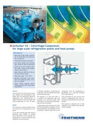
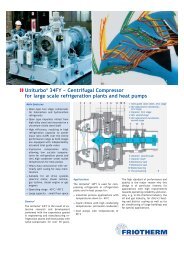
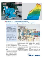
<strong>Compressor</strong> design<br />
The two high-efficiency impellers are<br />
mounted at the free end of the shaft<br />
which is supported on the driver side<br />
only. This permits axial arrangement<br />
of the suction inlet, resulting in undisturbed<br />
refrigerant flow, thus increasing<br />
the overall efficiency of the<br />
compressor.<br />
The open type impellers are milled<br />
from high-alloy steel and mounted on<br />
the shaft made from the same material<br />
by using the hydraulic fit technique.<br />
The advantage of this kind of<br />
connection is that a later iteration on<br />
site is easily possible. This is beneficial<br />
<strong>for</strong> major overhaul of the rotor<br />
assembly, which is dynamically balanced<br />
as one unit.<br />
Each impeller is preceded by a row of<br />
guide vanes adjustable during operation,<br />
thus regulating mass flow and<br />
capacity of the compressor according<br />
to the demand. The guide vanes are<br />
actuated by electric or pneumatic<br />
servomotors.<br />
The compressor casing made from<br />
nodular cast iron is of the vertically<br />
split type, which is beneficial with respect<br />
to distortion, clearance and<br />
stress distribution in the material. It<br />
further facilitates easy inspection and<br />
maintenance. The side stream and the<br />
discharge nozzle are located laterally<br />
on opposite sides and directed upwards.<br />
The rotor assembly runs in two <strong>for</strong>celubricated,<br />
low-loss tilting pad bearings,<br />
taking up the radial <strong>for</strong>ces. The<br />
axial thrust is taken up by the same<br />
type of bearing located in between the<br />
two others.<br />
A double mechanical seal at the back<br />
of the second stage impeller separates<br />
the lube oil from the refrigerant circuit<br />
during operation. A steady flow of<br />
seal oil between the two mechanical<br />
seals is preventing refrigerant leakage<br />
to the atmosphere at all times. The<br />
bearings are supplied with lube oil<br />
from the oil system integrated on the<br />
base frame of the compressor assembly.<br />
The lube oil pressure is set at<br />
2.5 bar and the seal oil pressure is<br />
maintained at 1.5 bar above the gas<br />
pressure. The seal oil system securely<br />
prevents the escape of refrigerant to<br />
the atmosphere. It also lubricates and<br />
cools the double shaft seal and the radial<br />
bearing placed between the two<br />
seals.<br />
Per<strong>for</strong>mance<br />
Economical operation of the refrigeration<br />
plant or of the heat pump is<br />
facilitated by the adaptation of the<br />
compressor to the very specific requirement<br />
of a particular plant.<br />
There<strong>for</strong>e, a number of design variables<br />
like guide vane settings, impeller<br />
geometry and impeller speed<br />
are adjustable within a certain range.<br />
Capacity control<br />
Design capacity is usually identical<br />
with the maximum capacity required<br />
<strong>for</strong> a specific application and is representing<br />
a single operating point only.<br />
For most applications, the capacity<br />
demand varies between 10% and 100%.<br />
For economic reasons it is there<strong>for</strong>e<br />
mandatory to match the compressor<br />
capacity with the actual demand. This<br />
is achieved by adapting the refrigerant<br />
flow with the individually controlled<br />
inlet guide vanes of both compressor<br />
stages, still maintaining the high efficiency<br />
of the unit.<br />
<strong>Compressor</strong> package<br />
The compressor package is shipped as<br />
completely assembled unit, ready <strong>for</strong><br />
operation.<br />
It basically consists of:<br />
• the compressor<br />
• an external spur-type gear or planetary<br />
type, if speed increase is required<br />
• a mechanical coupling<br />
• the oil tank, also used as base frame<br />
• the lube oil system and the seal oil<br />
system<br />
In cases the driver speed has to be increased<br />
to match with the compressor<br />
design, a spur-type or planetary type<br />
gear is incorporated. It is designed to<br />
meet power requirements and speed<br />
ratio with minimal mechanical losses.<br />
The coupling between compressor and<br />
gear is of the solid type. Between gear<br />
and motor it is of the toothed or membrane<br />
type. Since the gear does not<br />
develop an axial thrust, there is no<br />
need to equip it with thrust bearings.<br />
4