Uniturbo® 50FY â Centrifugal Compressor for large scale - Friotherm
Uniturbo® 50FY â Centrifugal Compressor for large scale - Friotherm Uniturbo® 50FY â Centrifugal Compressor for large scale - Friotherm
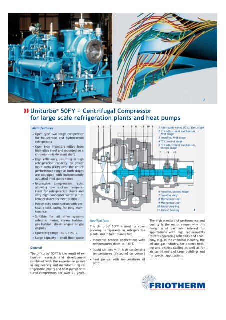
Uniturbo ® 50FY – Centrifugal Compressor for large scale refrigeration plants and heat pumps Main features • Open-type two stage compressor for halocarbon and hydrocarbon refrigerants • Open type impellers milled from high-alloy steel and mounted on a chromium-nickle steel shaft • High efficiency, resulting in high refrigeration capacity to power input ratio (COP) over the entire performance range as both stages are equipped with independently actuated inlet guide vanes • Impressive compression ratio, allowing low suction temperatures for refrigeration plants and very high condenser water outlet temperatures for heat pumps • Heavy duty construction with vertically split casing for easy maintenance • Suitable for all drive systems (electric motor, steam turbine, gas turbine, diesel engine or gas engine) • Operating range –40°C/+90°C • Large capacity – small floor space General The Uniturbo ® 50FY is the result of extensive research and development combined with the experience gained in engineering and manufacturing refrigeration plants and heat pumps with turbo-compressors for over 70 years. 1 Applications The Uniturbo ® 50FY is used for compressing refrigerants in refrigeration plants and in heat pumps for: • industrial process applications with temperatures down to –40°C • liquid chillers with high condensing temperatures (aircooled condenser) • heat pumps with temperatures of 90°C 1 Inlet guide vanes (IGV), first stage 2 IGV adjustment mechanism, first stage 3 Impeller, first stage 4 IGV, second stage 5 IGV adjustment mechanism, second stage 6 Impeller, second stage 7 Impeller shaft 8 Mechanical seal 9 Mechanical seal 10 Radial bearing 11 Thrust bearing The high standard of performance and quality is the major reason why this design is of particular interest for applications with high requirements towards operating reliability and economy, e.g. in the chemical industry, the oil and gas industry, for district heating and district cooling as well as for air conditioning of large buildings and for special applications. 3 2
- Page 2 and 3: Compressor design The two high-effi
- Page 4: Uniturbo ® range of compressors, m
Uniturbo ® <strong>50FY</strong> – <strong>Centrifugal</strong> <strong>Compressor</strong><br />
<strong>for</strong> <strong>large</strong> <strong>scale</strong> refrigeration plants and heat pumps<br />
Main features<br />
• Open-type two stage compressor<br />
<strong>for</strong> halocarbon and hydrocarbon<br />
refrigerants<br />
• Open type impellers milled from<br />
high-alloy steel and mounted on a<br />
chromium-nickle steel shaft<br />
• High efficiency, resulting in high<br />
refrigeration capacity to power<br />
input ratio (COP) over the entire<br />
per<strong>for</strong>mance range as both stages<br />
are equipped with independently<br />
actuated inlet guide vanes<br />
• Impressive compression ratio,<br />
allowing low suction temperatures<br />
<strong>for</strong> refrigeration plants and<br />
very high condenser water outlet<br />
temperatures <strong>for</strong> heat pumps<br />
• Heavy duty construction with vertically<br />
split casing <strong>for</strong> easy maintenance<br />
• Suitable <strong>for</strong> all drive systems<br />
(electric motor, steam turbine,<br />
gas turbine, diesel engine or gas<br />
engine)<br />
• Operating range –40°C/+90°C<br />
• Large capacity – small floor space<br />
General<br />
The Uniturbo ® <strong>50FY</strong> is the result of extensive<br />
research and development<br />
combined with the experience gained<br />
in engineering and manufacturing refrigeration<br />
plants and heat pumps with<br />
turbo-compressors <strong>for</strong> over 70 years.<br />
1<br />
Applications<br />
The Uniturbo ® <strong>50FY</strong> is used <strong>for</strong> compressing<br />
refrigerants in refrigeration<br />
plants and in heat pumps <strong>for</strong>:<br />
• industrial process applications with<br />
temperatures down to –40°C<br />
• liquid chillers with high condensing<br />
temperatures (aircooled condenser)<br />
• heat pumps with temperatures of<br />
90°C<br />
1 Inlet guide vanes (IGV), first stage<br />
2 IGV adjustment mechanism,<br />
first stage<br />
3 Impeller, first stage<br />
4 IGV, second stage<br />
5 IGV adjustment mechanism,<br />
second stage<br />
6 Impeller, second stage<br />
7 Impeller shaft<br />
8 Mechanical seal<br />
9 Mechanical seal<br />
10 Radial bearing<br />
11 Thrust bearing<br />
The high standard of per<strong>for</strong>mance and<br />
quality is the major reason why this<br />
design is of particular interest <strong>for</strong><br />
applications with high requirements<br />
towards operating reliability and economy,<br />
e.g. in the chemical industry, the<br />
oil and gas industry, <strong>for</strong> district heating<br />
and district cooling as well as <strong>for</strong><br />
air conditioning of <strong>large</strong> buildings and<br />
<strong>for</strong> special applications.<br />
3<br />
2
<strong>Compressor</strong> design<br />
The two high-efficiency impellers are<br />
mounted at the free end of the shaft<br />
which is supported on the driver side<br />
only. This permits axial arrangement<br />
of the suction inlet, resulting in undisturbed<br />
refrigerant flow, thus increasing<br />
the overall efficiency of the<br />
compressor.<br />
The open type impellers are milled<br />
from high-alloy steel and mounted on<br />
the shaft made from the same material<br />
by using the hydraulic fit technique.<br />
The advantage of this kind of<br />
connection is that a later iteration on<br />
site is easily possible. This is beneficial<br />
<strong>for</strong> major overhaul of the rotor<br />
assembly, which is dynamically balanced<br />
as one unit.<br />
Each impeller is preceded by a row of<br />
guide vanes adjustable during operation,<br />
thus regulating mass flow and<br />
capacity of the compressor according<br />
to the demand. The guide vanes are<br />
actuated by electric or pneumatic<br />
servomotors.<br />
The compressor casing made from<br />
nodular cast iron is of the vertically<br />
split type, which is beneficial with respect<br />
to distortion, clearance and<br />
stress distribution in the material. It<br />
further facilitates easy inspection and<br />
maintenance. The side stream and the<br />
discharge nozzle are located laterally<br />
on opposite sides and directed upwards.<br />
The rotor assembly runs in two <strong>for</strong>celubricated,<br />
low-loss tilting pad bearings,<br />
taking up the radial <strong>for</strong>ces. The<br />
axial thrust is taken up by the same<br />
type of bearing located in between the<br />
two others.<br />
A double mechanical seal at the back<br />
of the second stage impeller separates<br />
the lube oil from the refrigerant circuit<br />
during operation. A steady flow of<br />
seal oil between the two mechanical<br />
seals is preventing refrigerant leakage<br />
to the atmosphere at all times. The<br />
bearings are supplied with lube oil<br />
from the oil system integrated on the<br />
base frame of the compressor assembly.<br />
The lube oil pressure is set at<br />
2.5 bar and the seal oil pressure is<br />
maintained at 1.5 bar above the gas<br />
pressure. The seal oil system securely<br />
prevents the escape of refrigerant to<br />
the atmosphere. It also lubricates and<br />
cools the double shaft seal and the radial<br />
bearing placed between the two<br />
seals.<br />
Per<strong>for</strong>mance<br />
Economical operation of the refrigeration<br />
plant or of the heat pump is<br />
facilitated by the adaptation of the<br />
compressor to the very specific requirement<br />
of a particular plant.<br />
There<strong>for</strong>e, a number of design variables<br />
like guide vane settings, impeller<br />
geometry and impeller speed<br />
are adjustable within a certain range.<br />
Capacity control<br />
Design capacity is usually identical<br />
with the maximum capacity required<br />
<strong>for</strong> a specific application and is representing<br />
a single operating point only.<br />
For most applications, the capacity<br />
demand varies between 10% and 100%.<br />
For economic reasons it is there<strong>for</strong>e<br />
mandatory to match the compressor<br />
capacity with the actual demand. This<br />
is achieved by adapting the refrigerant<br />
flow with the individually controlled<br />
inlet guide vanes of both compressor<br />
stages, still maintaining the high efficiency<br />
of the unit.<br />
<strong>Compressor</strong> package<br />
The compressor package is shipped as<br />
completely assembled unit, ready <strong>for</strong><br />
operation.<br />
It basically consists of:<br />
• the compressor<br />
• an external spur-type gear or planetary<br />
type, if speed increase is required<br />
• a mechanical coupling<br />
• the oil tank, also used as base frame<br />
• the lube oil system and the seal oil<br />
system<br />
In cases the driver speed has to be increased<br />
to match with the compressor<br />
design, a spur-type or planetary type<br />
gear is incorporated. It is designed to<br />
meet power requirements and speed<br />
ratio with minimal mechanical losses.<br />
The coupling between compressor and<br />
gear is of the solid type. Between gear<br />
and motor it is of the toothed or membrane<br />
type. Since the gear does not<br />
develop an axial thrust, there is no<br />
need to equip it with thrust bearings.<br />
4
Typical lube and seal oil system<br />
➉<br />
Lube oil and seal oil systems<br />
A common lube oil system supplies<br />
bearings and gear. It comprises mainly<br />
of the oil tank with oil pumps, oil<br />
cooler, filters, heaters and the piping<br />
and controls required.<br />
Oil tank and pumps are designed to ensure<br />
adequate lubrication of the compressor<br />
package at all times and conditions.<br />
During start up and shutdown,<br />
an electrically driven auxiliary oil<br />
pump is in operation. At full compressor<br />
speed the main oil pump, mechanically<br />
driven from the gear box is taking<br />
over. The oil cooler can either be<br />
designed to work with cooling water or<br />
with refrigerant. Twin oil coolers, <strong>for</strong><br />
changeover during operation, retain<br />
solid particles from the oil flow, thus<br />
preventing damage to the equipment.<br />
➀<br />
➇<br />
➈<br />
➁<br />
➃<br />
➄<br />
➂<br />
Unitop ® <strong>50FY</strong> units<br />
Unitop ® <strong>50FY</strong> refrigeration plants or<br />
heat pumps basically consist of the<br />
Uniturbo ® <strong>50FY</strong> compressor package as<br />
described above.<br />
Usually supplied as a second single-lift<br />
package are the heat exchangers<br />
(evaporator, condenser, subcooler),<br />
the intermediate stage pressure vessel<br />
and all related instruments, valves,<br />
piping and wiring.<br />
The standard control system is designed<br />
<strong>for</strong> fully automatic operation of<br />
the plant.<br />
Many pre-engineered, modular plant<br />
concepts are available <strong>for</strong> various<br />
types of drivers and heat exchangers,<br />
such as plate evaporators or air-cooled<br />
condensers.<br />
➅<br />
➆<br />
Components<br />
➀ Turbo compressor<br />
➁ Spur type gear<br />
➂ Lube oil tank<br />
➃ Auxiliary lube oil pump<br />
➄ Main lube oil pump<br />
➅ Lube oil cooler<br />
➆ Lube oil filters<br />
➇ Seal oil tank<br />
➈ Seal oil pump<br />
➉ Seal oil cooler<br />
Media<br />
Lube oil supply<br />
Seal oil supply<br />
Refrigerant<br />
Cooling water<br />
5<br />
1 Base frame<br />
and lube oil<br />
tank<br />
2 <strong>Centrifugal</strong><br />
compressor<br />
3 Spur gear<br />
4 Main lube<br />
oil pump<br />
5 Lube oil<br />
cooler<br />
6 Refrigerant<br />
twin<br />
separator<br />
7 Auxiliary<br />
lube oil<br />
pump<br />
8 Lube oil<br />
twin filter<br />
9 Seal oil<br />
accumulator
Uniturbo ® range of compressors, marked in dark blue the data <strong>for</strong> Uniturbo ® <strong>50FY</strong><br />
Condensation temperature (°C)<br />
95<br />
90<br />
85<br />
80<br />
75<br />
70<br />
65<br />
60<br />
22AY 28CY 33CY<br />
Legend<br />
1 Uniturbo ® <strong>50FY</strong> compressor package,<br />
with base frame and integrated oil tank.<br />
Left the oil cooler and in the background,<br />
centre, the gear.<br />
2 Optimisation of an inducer at high Mach<br />
numbers with numerical 3D-CDF-method.<br />
3 Cross-section of a Unitop ® <strong>50FY</strong> compressor.<br />
G008-05 Subject to technical change<br />
34FY <strong>50FY</strong><br />
55<br />
0 2000 4000 6000 8000 10000 12000 14000 16000 18000 20000<br />
Heat capacity (kW)<br />
4 3D-front-view of a heat pump installation<br />
with a Unitop ® <strong>50FY</strong> compressor.<br />
5 3D-back-view of a heat pump installation<br />
with a Unitop ® <strong>50FY</strong> compressor.<br />
6 Machine room with a heat pump installation.<br />
Right the compressor assembly, left<br />
the heat exchangers.<br />
Technical Data<br />
Heating/cooling capacities see chart<br />
<strong>Compressor</strong> design pressure 25/40 bar<br />
Max. compressor shaft input 9,500 kW<br />
Size of suction flange, diameter 600 mm<br />
Size of discharge flange, diameter 350 mm<br />
Weight of complete package 20,000 kg<br />
Weight of bare compressor 6,000 kg<br />
Most heavy single part <strong>for</strong> service 1,100 kg<br />
Construction materials<br />
<strong>Compressor</strong><br />
• inlet housing nodular cast iron<br />
• casing parts nodular cast iron<br />
• guide vane carrier nodular cast iron<br />
• inlet guide vanes high-alloy steel<br />
• impellers high-alloy steel<br />
• compressor shaft<br />
Coupling<br />
high-alloy steel<br />
• shaft<br />
Gear<br />
Cr steel, <strong>for</strong>ged<br />
• casing cast iron<br />
• shaft and wheels<br />
Other<br />
Cr steel, <strong>for</strong>ged<br />
• refrigerant pipe work carbon steel<br />
• oil pipe work carbon steel and<br />
stainless steel<br />
<strong>Friotherm</strong> AG<br />
Zürcherstrasse 12 · P.O.Box 414<br />
CH-8400 Winterthur · Switzerland<br />
Tel. +41(0)52262-8080 · Fax -0003<br />
E-Mail info@friotherm.com<br />
Internet www.friotherm.com<br />
6


