HT Heater Specs Sheet - DDB Unlimited, Inc.
HT Heater Specs Sheet - DDB Unlimited, Inc.
HT Heater Specs Sheet - DDB Unlimited, Inc.

Create successful ePaper yourself
Turn your PDF publications into a flip-book with our unique Google optimized e-Paper software.
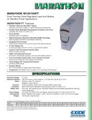
W A T L O W<br />
• Same day shipment on stock units with orders<br />
received by 11:00 a.m.<br />
Flexible <strong>Heater</strong>s<br />
Silicone Rubber<br />
Rugged, yet thin, lightweight and<br />
flexible … the use of Watlow silicone<br />
rubber heaters is limited only by your<br />
imagination. With these heaters, you<br />
can put the heat where it’s needed<br />
and, in the process, improve heat<br />
transfer, speed warm-ups and<br />
decrease wattage requirements.<br />
Fiberglass-reinforced silicone<br />
rubber gives your heater dimensional<br />
stability without sacrificing flexibility.<br />
Because very little material separates<br />
the element from the part, heat<br />
transfer is rapid and efficient.<br />
Performance Capabilities<br />
• Operating temperatures to 500°F<br />
(260°C)<br />
• Watt densities to 80 W/in2<br />
(12.5 W/cm2) dependent upon<br />
application temperature<br />
• 0.055 inch (1.4 mm) thick with a<br />
wire-wound element; only 0.018<br />
inch (0.5 mm) with an etched foil<br />
element<br />
Features and Benefits<br />
• Designed in the exact shape<br />
and size, including 3-D<br />
geometries, to conform to<br />
your equipment.<br />
• More than 80 designs available<br />
immediately from stock.<br />
• UR®, cUR® and VDE recognitions<br />
are available on many designs.<br />
• Moisture and chemical-resistant<br />
silicone rubber material provides<br />
longer heater life.<br />
• Easy to bond or attach to your<br />
part through the use of vulcanizing,<br />
adhesives, or fasteners.<br />
Applications<br />
• Freeze protection and condensation<br />
prevention for many types<br />
of instrumentation and equipment<br />
• Medical equipment such as blood<br />
analyzers, test tube heaters, etc.<br />
• Computer peripherals such as<br />
laser printers<br />
• Curing of plastic laminates<br />
• Photo processing equipment<br />
0.055" (1.4 mm)<br />
Thick <strong>Heater</strong> with<br />
Wire-Wound Element<br />
0.018" (0.5 mm) Thick <strong>Heater</strong><br />
with Etched Foil Element<br />
Teflon® is a registered trademark of the E.I.<br />
du Pont de Nemours & Company.<br />
Teflon ® , Silicone,<br />
or Neoprene Leads<br />
Available<br />
Element Vulcanized<br />
Between Two Layers of<br />
Silicone Rubber/Fiberglass<br />
UR® and cUR® are registered trademarks of<br />
Underwriter's Laboratories, <strong>Inc</strong>.<br />
169<br />
Flexible <strong>Heater</strong>s
Wire wound,<br />
on-off control<br />
Flexible <strong>Heater</strong>s<br />
Silicone Rubber<br />
Applications and<br />
Technical Data<br />
500<br />
Maximum Allowable Watt Density<br />
Watt Density–W/cm 2<br />
1 2 3 4 5 6 7 8 9 10 11 12 13 14 15<br />
250<br />
Determining Watt Density<br />
The Maximum Allowable Watt<br />
Density graph illustrates the<br />
maximum recommended heater<br />
watt density at various metal part or<br />
ambient air temperatures. However,<br />
it does not indicate the watt density<br />
necessary to achieve a given part<br />
temperature. See the Surface<br />
Temperature vs. Time graph on the<br />
next page for assistance with those<br />
calculations. When using this graph,<br />
remember:<br />
• Part temperature is measured at<br />
the point where the heater<br />
contacts the metal part.<br />
• Thermostats and on-off controls<br />
are typically bimetal or capillary<br />
bulb.<br />
• Non-cycling controls are typically<br />
solid state, time-proportioning or<br />
SCR temperature controllers.<br />
• Watt density values should be<br />
derated by one third if insulation<br />
is used.<br />
• UL® recognition temperature<br />
limits are not detailed.<br />
• Consult Watlow before doing any<br />
of the following: selecting high<br />
watt density etched-foil elements,<br />
or operating heaters with back<br />
side insulation or non-metallic<br />
parts, which are poor thermal<br />
conductors.<br />
Example: A wire-wound heater<br />
with non-cycling control at a part<br />
temperature of 250°F (120°C) can<br />
be rated at 24 W/in2 (3.7 W/cm2)<br />
maximum. An etched foil heater<br />
under the same conditions can<br />
be rated at 45 W/in2 (7 W/cm2)<br />
maximum.<br />
Part Temperature–°F<br />
400<br />
300<br />
200<br />
100<br />
0<br />
Wire wound, in open air<br />
Wire wound, non-cycling control<br />
Etched Foil<br />
10 20 30 40 50 60 70 80 90 100<br />
Watt Density–W/in 2<br />
Standard Silicone Rubber Specifications<br />
Maximum width x maximum length:<br />
• Wire wound: 36 x 120 inches (915 mm x 3050 mm)<br />
• Etched foil: 20 x 30 inches (510 mm x 760 mm)<br />
Thickness (standard):<br />
• Wire wound: 0.055 inch (1.4 mm)<br />
• Etched foil: 0.018 inch (0.5 mm)<br />
Weight (standard):<br />
• Wire wound: 8 oz./ft2 (0.24 g/cm2)<br />
• Etched foil: 3 oz./ft2 (0.09 g/cm2)<br />
Maximum operating temperature: 500°F (260°C)<br />
Maximum temperature for UL® recognition: 428°F (220°C)<br />
Minimum ambient temperature: -80°F (-62°C)<br />
Maximum voltage: 600VÅ(ac)<br />
Maximum wattage: See watt density graph<br />
Lead size: Sized to load<br />
Lead length: 12 + 1 1 ⁄2 - 1 ⁄2 inches (305 mm + 40 mm - 15 mm)<br />
Wattage tolerance:<br />
• Wire: ±5 percent<br />
• Foil: +5 percent -10 percent<br />
Dimensional tolerances:<br />
• 0 to 6 inches (0 to 150 mm): ± 1 ⁄16 inch (1.6 mm)<br />
• 6 to 18 inches (150 to 455 mm): ± 1 ⁄8 inch (3.2 mm)<br />
• 18 to 36 inches (455 mm to 915 mm): ± 3 ⁄16 inch (4.8 mm)<br />
• Over 36 inches (915 mm): ±1 percent<br />
Government Supply Code Number<br />
Cage code = 78056<br />
200<br />
150<br />
100<br />
50<br />
0<br />
Part Temperature–°C<br />
UL® is registered trademark of<br />
Underwriter's Laboratories, <strong>Inc</strong>.<br />
170
Flexible <strong>Heater</strong>s<br />
Silicone Rubber<br />
Stock Product Offering<br />
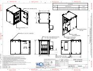
Enclosure <strong>Heater</strong>s<br />
Options<br />
Aluminum Mounting Plate<br />
Both vertical and horizontal<br />
mounting can be accomplished<br />
with enclosure heaters. The mounting<br />
plates are 0.040 inch<br />
(1 mm) thick, specified as #3003<br />
H14 aluminum. The preferred<br />
orientation is vertical, with a<br />
thermostat attached at the lower<br />
end (as shown in the drawing).<br />
<strong>Heater</strong><br />
Width<br />
For horizontal mounting, a remote<br />
thermostat is recommended. An<br />
enclosure heater can be ordered by<br />
itself, with PSAS or vulcanized to an<br />
aluminum mounting plate. See<br />
Thermostats below for more<br />
information.<br />
1 /2"<br />
(13 mm)<br />
7<br />
/32" X 1 /2"<br />
(5 X 13 mm)<br />
Slot Typ.<br />
<strong>Heater</strong> Length<br />
5" (127 mm) Typ.<br />
See Note ➀ 1<br />
0.040" (1.0 mm)<br />
Aluminum<br />
0.065" (1.7 mm)<br />
<strong>Heater</strong><br />
1 /2" (13 mm)<br />
0.53" (13.5 mm)<br />
0.75" (19 mm)<br />
0.75"<br />
(19 mm)<br />
1.25"<br />
(32 mm)<br />
2.5"<br />
(63.5 mm) Typ.<br />
See Note 2 ➁<br />
➀ 4.0 inches (102 mm) on 5 inch unit.<br />
➁ 0.50 inch (12.7 mm) on 5 inch unit.<br />
1 /2"<br />
(13 mm)<br />
Thermostats<br />
Mounted on <strong>Heater</strong><br />
Built-in snap action thermostats from<br />
Watlow are designed to sense air<br />
temperature. See the ordering chart<br />
on the following page for available<br />
settings.<br />
Remote From <strong>Heater</strong><br />
For an air sensing thermostat<br />
separate from the heater, the<br />
ST-207E is ideal. This is a modified<br />
ST-207 mounted on a 1 ⁄32 inch<br />
(0.8 mm) thick G-10 circuit board<br />
with the thermostat’s metal cap<br />
exposed to sense air temperature.<br />
The thermostat is placed at the<br />
midpoint of the lead length.<br />
The sensor can be preset at the<br />
temperatures listed for integral<br />
sensors. For more information,<br />
turn to pages 167-168.<br />
Notes:<br />
• On both integral and remote<br />
sensors, the thermostat’s<br />
exposed metal cap is vulnerable<br />
to impact. This could defeat the<br />
thermostat’s switching action and<br />
cause heater malfunction.<br />
• T-10 thermostats are not<br />
recommended for enclosure<br />
heating applications.<br />
178