253-421
253-421
253-421

Create successful ePaper yourself
Turn your PDF publications into a flip-book with our unique Google optimized e-Paper software.
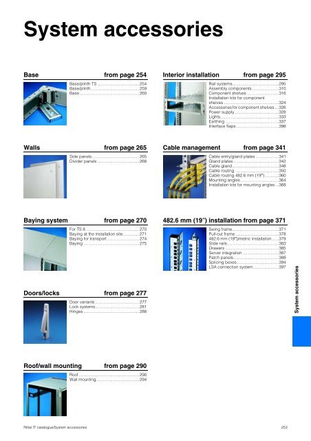
System accessories<br />
Base from page 254<br />
Base/plinth TS ....................................254<br />
Base/plinth..........................................259<br />
Base ...................................................260<br />
Interior installation from page 295<br />
Rail systems........................................295<br />
Assembly components.......................310<br />
Component shelves............................316<br />
Installation kits for component<br />
shelves ...............................................324<br />
Accessories for component shelves....326<br />
Power supply......................................328<br />
Lights..................................................333<br />
Earthing ..............................................337<br />
Interface flaps.....................................398<br />
Walls from page 265<br />
Side panels.........................................265<br />
Divider panels ....................................268<br />
Cable management from page 341<br />
Cable entry/gland plates ....................341<br />
Gland plates .......................................342<br />
Cable gland........................................348<br />
Cable routing .....................................350<br />
Cable routing 482.6 mm (19″) ............360<br />
Mounting angles.................................364<br />
Installation kits for mounting angles ...368<br />
Baying system from page 270<br />
For TS 8 ..............................................270<br />
Baying at the installation site..............271<br />
Baying for transport............................274<br />
Baying ................................................275<br />
Doors/locks from page 277<br />
Door variants ......................................277<br />
Lock systems......................................281<br />
Hinges ................................................288<br />
482.6 mm (19″) installation from page 371<br />
Swing frame........................................371<br />
Pull-out frame......................................378<br />
482.6 mm (19″)/metric installation......379<br />
Slide rails ............................................383<br />
Drawers ..............................................385<br />
Server integration ...............................387<br />
Patch panels.......................................388<br />
Splicing boxes....................................394<br />
LSA connection system......................397<br />
System accessories<br />
Roof/wall mounting from page 290<br />
Roof ....................................................290<br />
Wall mounting.....................................294<br />
Rittal IT catalogue/System accessories<br />
<strong>253</strong>
Base<br />
Base/plinth TS<br />
One Model No.<br />
for the<br />
base/plinth components<br />
front and rear.<br />
One Model No.<br />
for the<br />
base/plinth trims<br />
at the sides.<br />
A complete<br />
base/plinth TS.<br />
Modular base/plinth diversity<br />
Regardless of the enclosure depth:<br />
The base/plinth components at the front and rear,<br />
pre-configured with corner pieces, are always the<br />
same for the chosen width.<br />
Only the side trim panels are selected according<br />
to the enclosure depth and the required base/<br />
plinth configuration. The modular concept produces<br />
exceptional advantages in terms of cost<br />
and function.<br />
Assembly to the enclosure is conveniently carried<br />
out from the outside. The base/plinth interior offers<br />
diverse opportunities for mounting levels for cable<br />
management.<br />
Base/plinth<br />
height<br />
Basic form<br />
Cable gland options<br />
Stabilisation of bayed base/plinth<br />
100 mm<br />
200 mm<br />
Function and cost benefits<br />
Fewer parts, more opportunities, lower purchasing,<br />
storage and assembly costs – the formular for<br />
the new modular base/plinth system.<br />
The following table shows three bayed base/<br />
plinths in 200 mm height illustrating a wide range<br />
of possible solutions and the potential savings<br />
with trim panels compared with the previous<br />
200 mm base/plinth system each with two trim<br />
panels of 100 mm height at the sides.<br />
Sample solutions New supply includes Functional benefits<br />
3 packs of base/plinth components<br />
1 pack of base/plinth trim panels<br />
200 mm high<br />
Continuous<br />
cable chamber<br />
Savings potential compared with<br />
twelve 100 mm trim panels<br />
2 trim panels 200 mm<br />
Base/plinth TS<br />
3 packs of base/plinth components<br />
1 pack of base/plinth trim panels<br />
200 mm high<br />
1 pack of base/plinth trim panels<br />
100 mm high<br />
1 pack of base/plinth baying bracket<br />
TS 8601.100 (packs of 20)<br />
4 units are required for this solution<br />
Additional stabilisation<br />
for transportation purposes with<br />
base/plinth trim rotated through 90°<br />
2 trim panels 200 mm<br />
2 trim panels 100 mm<br />
3 packs of base/plinth components<br />
2 packs of base/plinth trim panels<br />
200 mm high<br />
Shielding of the base/plinths<br />
from one another<br />
4 trim panels 200 mm<br />
3 packs of base/plinth components<br />
1 pack of base/plinth trim panels<br />
200 mm high<br />
1 pack base/plinth trim panels 100 mm<br />
high<br />
Additional connection<br />
of the base/plinth<br />
2 trim panels 200 mm<br />
2 trim panels 100 mm<br />
Other options:<br />
● Cable entry at the side by mounting a 100 mm<br />
base/plinth trim panel (top or bottom).<br />
● Cable entry from the rear by dismantling one<br />
or more trim panels of the base/plinth components.<br />
● Cable clamp rail fitted on the 100 mm high trim panel.<br />
254 Rittal IT catalogue/System accessories
Base<br />
Base/plinth TS<br />
Base/plinth components<br />
front and rear<br />
Sheet steel<br />
for TS, CM, PC-TS, IW, FR(i), TE<br />
Base/plinth component consisting of one trim<br />
panel and two pre-configured corner pieces.<br />
In 200 mm high base/plinth components, one<br />
trim panel is divided into two for cable entry.<br />
Material:<br />
Sheet steel, spray-finished<br />
Cover caps plastic RAL 9005/7035<br />
Supply includes:<br />
1 set =<br />
2 base/plinth components, 4 cover caps,<br />
4 screws and captive nuts M12<br />
for attachment to the enclosure.<br />
Accessories:<br />
Base assembly plate SO 2817.000,<br />
see page 257.<br />
Filter mats for vented versions,<br />
see page 258.<br />
Detailed drawing,<br />
see page 256.<br />
German patent no. 198 60 408<br />
For enclosure width<br />
Colour<br />
Model No. TS<br />
Design<br />
mm<br />
RAL 7022 RAL 7035 100 mm high 200 mm high<br />
300 Solid – 8601.905 8602.905<br />
400 Solid – 8601.400 8602.400<br />
500 Solid – 8601.500 8602.500<br />
600<br />
Solid – 8601.600 8602.600<br />
Solid – 8601.605 1) 8602.605<br />
Vented – 7825.601 2) –<br />
Vented<br />
with designer cover<br />
– 7825.603 –<br />
Solid – 8601.800 8602.800<br />
Solid – 8601.805 3) 8602.805<br />
800<br />
Vented – 7825.801 4) –<br />
Vented<br />
with designer cover<br />
– 7825.803 –<br />
850 Solid – 8601.850 8602.850<br />
1000 Solid – 8601.000 8602.000<br />
1100 Solid – 8601.300 8602.100<br />
1200 Solid – 8601.200 8602.200<br />
1) Design in RAL 9005: TS 8601.602<br />
2) Design in RAL 9005: DK 7825.605<br />
3) Design in RAL 9005: TS 8601.802<br />
4) Design in RAL 9005: DK 7825.805<br />
Base/plinth trim, side<br />
Sheet steel<br />
for TS, CM, PC-TS, IW, FR(i), TE<br />
For mounting between the base/plinth components.<br />
At 200 mm height, two 100 mm base/plinth<br />
trims may be used. Base/plinth trim panels<br />
(100 mm high) may be installed rotated through<br />
90° in order to stabilise bayed base/plinth components.<br />
Material:<br />
Sheet steel, spray-finished<br />
Supply includes:<br />
1 set =<br />
2 base/plinth trim panels, including parts for<br />
attaching to the base/plinth components.<br />
Also required:<br />
Base/plinth baying brackets TS 8601.100,<br />
see page 257,<br />
when base/plinth components are fitted by<br />
rotating through 90°.<br />
Accessories:<br />
Fastening bolts for baying base/plinth trim,<br />
see page 257.<br />
Detailed drawing,<br />
see page 256.<br />
Base/plinth TS<br />
For enclosure depth<br />
Colour<br />
Model No. TS<br />
mm<br />
RAL 7022 RAL 7035 100 mm high 200 mm high<br />
300 – 8601.030 8602.030<br />
400 – 8601.040 8602.040<br />
500 – 8601.050 8602.050<br />
600<br />
– 8601.060 8602.060<br />
– 8601.065 8602.065<br />
800<br />
– 8601.080 8602.080<br />
– 8601.085 1) 8602.085<br />
900 – 8601.095 2) 8602.095<br />
1000 – 8601.015 3) 8602.015<br />
1200 – 8601.025 4) 8602.025<br />
1)<br />
Design in RAL 9005: TS 8601.086<br />
2)<br />
Design in RAL 9005: TS 8601.092<br />
3)<br />
Design in RAL 9005: TS 8601.010<br />
4)<br />
Design in RAL 9005: TS 8601.026<br />
Rittal IT catalogue/System accessories<br />
255
Base<br />
Base/plinth TS<br />
Base/plinth TS<br />
Sheet steel<br />
92.5<br />
80<br />
32.5<br />
62.5<br />
14<br />
30<br />
18 x 14<br />
Plinth, 100 mm high<br />
T1<br />
T2<br />
T3<br />
T4<br />
B5<br />
T5<br />
15 x 10<br />
Ø 9.4<br />
50 47.5<br />
62.5<br />
30<br />
22<br />
100<br />
200<br />
Plinth, 200 mm high<br />
Description of the hole patterns<br />
B1/T1 = External dimensions<br />
B2/T2 = For screw-fastening in<br />
the thread of the enclosure<br />
corner piece from<br />
below<br />
B3/T3 = For screw-fastening<br />
with captive nuts to the<br />
enclosure base from<br />
below or above<br />
All holes (B2 – B4/T2 – T4) may<br />
be used for screw-fastening to<br />
the base.<br />
B4<br />
B3<br />
B3<br />
B2<br />
B1<br />
Base/plinth components front/rear<br />
Width<br />
Page<br />
B1 B2 B3 B4 B5<br />
mm<br />
300 300 235 175 115 270 255<br />
400 400 335 275 215 370 255<br />
500 500 435 375 315 470 255<br />
600 600 535 475 415 570 255<br />
800 800 735 675 615 770 255<br />
850 850 785 725 665 820 255<br />
1000 1000 935 875 815 970 255<br />
1100 1100 1035 975 915 1070 255<br />
1200 1200 1135 1075 1015 1170 255<br />
B = Width<br />
Base/plinth trims, side<br />
Depth<br />
Page<br />
T1 T2 T3 T4 T5<br />
mm<br />
300 269 235 175 144 268 255<br />
400 369 335 275 244 368 255<br />
500 469 435 375 344 468 255<br />
600 569 535 475 444 568 255<br />
800 769 735 675 644 768 255<br />
900 869 835 775 744 868 255<br />
1000 969 935 875 844 968 255<br />
1200 1169 1135 1075 1044 1168 255<br />
T = Depth<br />
Base/plinth TS<br />
Transport castors<br />
for base/plinth TS<br />
For locating onto the base/plinth corner piece<br />
100 or 200 mm high by raising or tilting.<br />
Load capacity:<br />
Maximum permissible load per twin castor:<br />
static: 100 kg<br />
Supply includes:<br />
1 set =<br />
4 twin castors,<br />
2 with, 2 without brakes.<br />
Colour:<br />
RAL 7022<br />
Note:<br />
Base/plinth trims, side, must be fitted in a freestanding<br />
position.<br />
Ground clearance<br />
mm<br />
Model No. TS<br />
100 8800.390<br />
Also required:<br />
Base/plinth trim, side,<br />
see page 255.<br />
256 Rittal IT catalogue/System accessories
Base<br />
Base/plinth TS<br />
Base assembly plate<br />
for base/plinth TS and base/plinth, complete<br />
For fastening the plinth to the floor without moving<br />
the enclosure or the bayed enclosure suite. For<br />
assembly screws up to 12 mm Ø.<br />
Material:<br />
Sheet steel, zinc-plated, passivated<br />
Packs of<br />
Model No. SO<br />
10 2817.000<br />
Fastening bolts<br />
for<br />
● Base/plinth TS<br />
● Base/plinth, complete<br />
● Base/plinth, stationary<br />
For mounting on base/plinth trim panels, side.<br />
The lockable assembly bolt allows the installation<br />
of cable clamp rails and standard C rails.<br />
Material:<br />
Hexagon steel, zinc-plated, passivated,<br />
19 mm across flats<br />
For base/plinth<br />
trim panel Packs of Model No. SZ<br />
height mm<br />
100 10 2819.000<br />
200 10 2819.200<br />
67<br />
117 1)<br />
167 1)<br />
1)<br />
only for height 200 mm<br />
Base/plinth baying brackets<br />
for base/plinth TS<br />
Essential if the trim panels are mounted rotated<br />
through 90° for additional stabilisation during the<br />
transportation of bayed enclosures.<br />
Additionally required for each trim panel: 2 units.<br />
Material:<br />
Sheet steel, zinc-plated, passivated<br />
Supply includes:<br />
Screws M8 x 16 mm.<br />
Packs of<br />
Model No. TS<br />
20 8601.100<br />
Base/plinth TS<br />
Cover cap<br />
for base/plinth components TS<br />
As a replacement.<br />
Material:<br />
Plastic ABS<br />
Colour:<br />
RAL 9005<br />
For base/plinth height<br />
mm<br />
Packs of Model No. TS<br />
100 4 8601.130<br />
200 4 8601.140<br />
Rittal IT catalogue/System accessories<br />
257
Base<br />
Base/plinth TS<br />
Version A<br />
Version B<br />
Base/plinth trim<br />
with brush strip<br />
for TS base/plinth<br />
The supplement to the modular base/plinth<br />
concept (see page 254).<br />
May also be exchanged retrospectively for the<br />
front or rear trim panel of the base/plinth components<br />
100 or 200 mm high.<br />
Material:<br />
Sheet steel, spray-finished<br />
Version A:<br />
By rotating the trim panel, the hammer-head strip<br />
for cable attachment may optionally be positioned<br />
at the top or bottom, sealed all-round for<br />
a high level of stability.<br />
Version B:<br />
Open on one side for retrospective mounting if<br />
cables have already been inserted.<br />
Version A<br />
Width Height<br />
Model No. TS<br />
mm mm RAL 7022 RAL 7035<br />
600 100 8601.610 8601.615<br />
800 100 8601.810 8601.815<br />
Accessories:<br />
Cable tie SZ 2597.000,<br />
see page 353.<br />
Version B<br />
Width Height<br />
Model No. TS<br />
mm mm RAL 7035 RAL 9005<br />
600 100 7825.607 7825.608<br />
800 100 7825.807 7825.808<br />
Connecting plinth trim<br />
for base/plinth TS<br />
For covering gaps in the case of back to back or<br />
corner enclosure suites. Simply push in between<br />
the trim panel and the corner piece before tightening<br />
the screws.<br />
Material:<br />
Sheet steel<br />
For<br />
base/plinth height<br />
mm<br />
Colour<br />
RAL<br />
Packs of<br />
Model No.<br />
TS<br />
100 7022 2 8601.110<br />
200 7022 2 8601.120<br />
100 7035 2 8601.115<br />
200 7035 2 8601.125<br />
Base/plinth TS<br />
Filter mat<br />
for<br />
● Base/plinth component, vented<br />
● Base/plinth component, vented with<br />
designer trim<br />
To cover the trim panel in the base/plinth component.<br />
The mounting frame slides into position<br />
behind the filter mat in the base/plinth trim panel.<br />
Filter class G3 to DIN EN 779.<br />
Supply includes:<br />
Assembly frame.<br />
For<br />
enclosure width Packs of Model No. DK<br />
mm<br />
600 1 7561.500<br />
800 1 7581.500<br />
Spare filter mat<br />
Supply includes:<br />
Filter mat without mounting frames for base/plinth<br />
trim panels up to 800 mm wide.<br />
Packs of Model No. DK<br />
Spare filter mats 5 7582.500<br />
258 Rittal IT catalogue/System accessories
Base<br />
Base/plinth<br />
Base/plinth<br />
for EL<br />
The base/plinth can be fitted onto all EL enclosures<br />
with a centre part depth of 316 or 416 mm.<br />
Holes must be made for attaching to the centre<br />
part. A drilling template is supplied. These may<br />
additionally be fitted with castors for use as a<br />
mobile base/plinth.<br />
Material:<br />
Sheet steel<br />
Colour:<br />
RAL 7044<br />
Supply includes:<br />
4 levelling feet<br />
and assembly parts.<br />
For centre part depth<br />
mm<br />
Packs<br />
of<br />
Height<br />
mm<br />
Model No.<br />
DK/VR<br />
316 1 50 7505.300 1)<br />
416 1 50 7505.400 1)<br />
Additional castors<br />
for base/plinth<br />
4 50 3805.500<br />
1) Delivery times available on request.<br />
Under-floor frame<br />
for DK-TS, FR(i)<br />
For siting the enclosure on a false floor when<br />
heavy equipment is installed.<br />
Material:<br />
Sheet steel<br />
Colour:<br />
RAL 7035<br />
Supply includes:<br />
Baying connector<br />
and base mounting bracket.<br />
Width<br />
mm<br />
Height<br />
mm<br />
Depth<br />
mm<br />
Model No. DK<br />
600 400 1000 7855.340<br />
800 400 1000 7855.342<br />
Delivery times available on request.<br />
Note:<br />
Other sizes available on request.<br />
Stabiliser bracket<br />
for base/plinth TS<br />
The stabiliser bracket may be retrospectively<br />
screw-fastened to the outside of the base/plinth<br />
corner pieces.<br />
Load capacity:<br />
Up to a maximum of 80 kg static load.<br />
Material:<br />
Sheet steel, spray-finished<br />
Colour:<br />
RAL 7035, warning markings RAL 2002<br />
Supply includes:<br />
Assembly parts.<br />
Packs of<br />
Model No. DK<br />
2 7825.150<br />
Base/plinth<br />
Rittal IT catalogue/System accessories<br />
259
Base<br />
Base/plinth<br />
Stabiliser<br />
for server racks DK-TS, FR(i)<br />
The pull-out stabiliser is quickly and easily retrofitted<br />
to the lower frame of the server racks and<br />
only extended when necessary. May be used in<br />
combination with levelling feet and/or transport kit<br />
for DK-TS (DK 7825.900), see page 261.<br />
Load capacity:<br />
Up to a maximum of 150 kg static load.<br />
Material:<br />
Sheet steel, zinc-plated<br />
Supply includes:<br />
Assembly parts.<br />
Enclosure depth mm<br />
Model No. DK<br />
900 7825.200<br />
1000 7825.250<br />
1200 7825.260<br />
Note:<br />
The stabiliser cannot be used with base plates,<br />
base frame or base/plinths.<br />
150kg<br />
Levelling feet<br />
18 – 43 mm high<br />
To compensate for height differences with floor<br />
irregularities. Thread length 40 mm.<br />
Assembly thread M12.<br />
Maximum permissible static load:<br />
approx. 300 kg per levelling foot.<br />
For:<br />
● Baying system TS 8<br />
● PC enclosure system<br />
● Pedestal base plate<br />
CP 6137.035 – CP 6137.535<br />
● Pedestal CP 6141.XXX<br />
● Industrial workstations<br />
● flexRack(i)<br />
Packs of<br />
Model No. PS<br />
4 4612.000<br />
Also required:<br />
For mounting on the TS base/plinth:<br />
Base/plinth adaptor TS 8800.220,<br />
see page 262.<br />
SW 19<br />
M12<br />
Base/plinth<br />
40<br />
18<br />
58<br />
Ø 47<br />
Levelling feet<br />
85 – 115 mm high<br />
For mounting on TS, ES and PC enclosures, for<br />
easier floor cleaning and to compensate for floor<br />
irregularities of ±15 mm.<br />
Height 100 mm.<br />
Maximum permissible static load:<br />
350 kg per levelling foot.<br />
Packs of<br />
Model No. SO<br />
4 2859.000<br />
Material:<br />
Feet: Brass, nickel-plated<br />
Threaded bolts and mounting plates:<br />
Stainless steel 1.4301 (AISI 304)<br />
Supply includes:<br />
Assembly parts to the enclosure.<br />
260 Rittal IT catalogue/System accessories
Base<br />
Base<br />
Twin castors<br />
Mounting thread M12 x 20.<br />
1<br />
Maximum permissible<br />
static load<br />
(per castor) kg<br />
Ground<br />
clearance<br />
mm<br />
Lock Packs of Colour Model No.<br />
40 50 4 without 1 set 1 Black 4611.000<br />
75 85<br />
120 125<br />
2 with,<br />
2 without<br />
2 with,<br />
2 without<br />
1 set<br />
2<br />
Black<br />
with grey<br />
running surface<br />
3<br />
1 set Black<br />
4<br />
6148.000<br />
4634.500<br />
7495.000<br />
2<br />
For:<br />
● Baying system TS 8<br />
● PC enclosure system<br />
● Pedestal base plate<br />
CP 6137.035 – CP 6137.535<br />
● Pedestal CP 6141.XXX<br />
● Industrial workstations<br />
● flexRack(i)<br />
● Data Rack<br />
Also required:<br />
For mounting on the TS base/plinth:<br />
Base/plinth adaptor for twin castors<br />
TS 8800.290,<br />
see page 262.<br />
3<br />
4<br />
Transport castors<br />
for TE<br />
For easy transportation between sites. The castors<br />
may be screw-fastened in the corner areas<br />
within the base frame in place of the levelling feet.<br />
Ground clearance: 58 mm,<br />
mounting thread M10 x 20<br />
Permissible static load:<br />
300 kg per enclosure<br />
Packs of<br />
Model No. TE<br />
1 set 7000.672<br />
Supply includes:<br />
1 set = 4 castors<br />
including assembly parts.<br />
Base<br />
Transport kit<br />
for DK-TS<br />
For convenient movement of the network enclosures<br />
or as a mobile rack. Ground clearance<br />
approx. 40 mm.<br />
Permissible static load:<br />
750 kg per enclosure<br />
Supply includes:<br />
1 set = 4 castors (2 steerable ones)<br />
including assembly parts.<br />
Packs of<br />
Model No. DK<br />
1 set 7825.900<br />
Note:<br />
Only for enclosures without gland plates or gland<br />
plate frames.<br />
For 800 mm wide enclosures with 19″ mounting<br />
frame, special installation dimensions must be<br />
observed (see drawing).<br />
min.<br />
79.5<br />
Rittal IT catalogue/System accessories<br />
261
Base<br />
Base<br />
Base/plinth adaptor<br />
for levelling feet<br />
Connection component for fastening M12 levelling<br />
feet PS 4612.000 to the TS base/plinth.<br />
Material:<br />
Sheet steel, zinc-plated, passivated<br />
Packs of<br />
Model No. TS<br />
4 8800.220<br />
Also required:<br />
Levelling feet, PS 4612.000,<br />
see page 260.<br />
Base/plinth adaptor<br />
for twin castors<br />
Connection component for mounting twin castors<br />
to the TS base/plinth.<br />
Material:<br />
Sheet steel, zinc-plated, passivated<br />
Packs of<br />
Model No. TS<br />
4 8800.290<br />
Also required:<br />
Base/plinth trim, side,<br />
see page 255,<br />
in all situations where a twin castor is mounted.<br />
Base assembly bracket<br />
for TS, ES, AR universal console, FR(i)<br />
For anchoring the enclosure at any position of the<br />
base frame, particularly in cases where the existing<br />
holes in the frame or base tray cannot be used<br />
due to the installed equipment or because the<br />
substructure prevents them from being used.<br />
Material:<br />
Sheet steel, zinc-plated, passivated<br />
Packs of<br />
Model No. TS<br />
4 8800.210<br />
Note:<br />
Additional holes in the base are required for<br />
mounting.<br />
Base<br />
262 Rittal IT catalogue/System accessories
Base<br />
Base<br />
One-piece gland plate<br />
vented, for DK-TS, FR(i)<br />
The slotted gland plate has a cut-out in the rear<br />
for cable entry, which is concealed with brush<br />
strips.<br />
Material:<br />
Sheet steel, zinc-plated<br />
Supply includes:<br />
Assembly parts.<br />
For enclosures<br />
Width mm Depth mm<br />
Model No. DK<br />
600 600 7825.660<br />
600 800 7825.680<br />
600 900 7825.690<br />
600 1000 7825.610<br />
800 600 7825.860<br />
800 800 7825.880<br />
800 900 7825.890<br />
800 1000 7825.810<br />
Accessories:<br />
Filter mat for gland plate,<br />
see page 263.<br />
Filter mat<br />
for one-piece gland plate<br />
To conceal the slotted area inside the one-piece<br />
vented gland plates for TS, FR(i). The filter mat is<br />
easily cut to the required cut-out and conveniently<br />
slides into position from the front via the<br />
guide rails of the gland plate.<br />
Packs of<br />
Model No. DK<br />
1 7825.620<br />
Material:<br />
PPI 35-5/polyamide<br />
Gland plate modules<br />
for DK-TS<br />
For use in the base frame of the network enclosure.<br />
Used in exchange for an existing gland<br />
plate of the same depth or in conjunction with a<br />
multi-piece gland plate for pre-configured TS 8<br />
enclosures, see page 263.<br />
Gland plate depth:<br />
237.5 mm<br />
Design for cable entry:<br />
With brush strip<br />
Vented design:<br />
With filter mat for concealing the holes and nylon<br />
tape for securing from the inside or outside.<br />
For<br />
enclosure<br />
width<br />
mm<br />
Model No. DK<br />
Design<br />
for cable entry<br />
vented<br />
600 7825.361 7825.360<br />
800 7825.381 7825.380<br />
Material:<br />
Sheet steel, zinc-plated<br />
Base<br />
Gland plate, multi-piece<br />
for DK-TS, pre-configured<br />
Gland plates including sliding panel for cable<br />
entry and foam rubber cable clamp strip for<br />
optional sealing.<br />
Material:<br />
Sheet steel, zinc-plated<br />
Supply includes:<br />
Assembly parts.<br />
Note:<br />
For the size variant 800 x 800 mm, the gland plate<br />
included with the supply for pre-configured network<br />
enclosures should be additionally used. Also<br />
suitable for combined use with vented gland plate<br />
modules and those for cable entry.<br />
Width<br />
mm<br />
For enclosures<br />
Depth<br />
mm<br />
Accessories:<br />
Gland plate modules,<br />
see page 263.<br />
Packs<br />
of<br />
Model No. DK<br />
800 800 1 set 7825.382<br />
800 900 1 set 7825.383<br />
800 1000 1 set 7825.384<br />
Rittal IT catalogue/System accessories<br />
263
Base<br />
Base<br />
Module plates<br />
for TE<br />
The base area of the TE may be varied as<br />
required using the module plates.<br />
Material:<br />
Sheet steel<br />
Supply includes:<br />
Assembly parts.<br />
Design<br />
Solid<br />
With<br />
brush strip<br />
Vented<br />
Compensating<br />
panel<br />
Width<br />
mm<br />
Depth<br />
mm<br />
Model No. TE<br />
450 200 7526.760<br />
450 550 7526.770<br />
450 750 7526.780<br />
650 550 7526.785<br />
650 200 7526.800<br />
650 750 7526.820<br />
450 200 7526.850<br />
650 200 7526.860<br />
450 200 7526.829<br />
650 200 7526.834<br />
450 50 7526.750<br />
450 150 7526.755<br />
650 50 7526.790<br />
650 150 7526.795<br />
Also required:<br />
For a completely sealed base assembly, the<br />
module plates should be combined with the<br />
compensating panels.<br />
T<br />
B<br />
Enclosure dimensions<br />
mm<br />
B 600 600 600 800 800 800<br />
T 600 800 1000 600 800 1000<br />
B1<br />
T1<br />
Base cut-out dimensions<br />
mm<br />
B1 450 450 450 650 650 650<br />
T1 550 750 950 550 750 950<br />
B = Width<br />
T = Depth<br />
Base<br />
264 Rittal IT catalogue/System accessories
Walls<br />
Side panels<br />
The TS side panel provides new<br />
dimensions in convenient<br />
access to the TS interior, thanks<br />
to the option of hinging.<br />
Important:<br />
Red areas (side panels), hinged<br />
and unhinged, must always be<br />
opposite one another. Blue<br />
areas (doors/rear panels) must<br />
always be opposite one another.<br />
Only one surface on each vertical<br />
enclosure section may be<br />
hinged.<br />
Note:<br />
Climate control side panels with<br />
integral cooling module may be<br />
retrofitted instead of an enclosure<br />
side panel, see Cat. 31,<br />
page 589.<br />
Automatic potential equalisation<br />
Side panels, screw-fastened,<br />
sheet steel<br />
for TS<br />
Easy positioning on the frame with the location<br />
aid. Six or eight enclosure panel holders with<br />
earthing insert ensure automatic potential equalisation<br />
and higher EMC protection. Earthing bolts<br />
with contact surface are integrated.<br />
Material:<br />
1.5 mm sheet steel<br />
Surface finish:<br />
Dipcoat-primed,<br />
powder-coated in textured RAL 7035 on the<br />
outside.<br />
Protection category:<br />
IP 55 as per EN 60 529/10.91<br />
Supply includes:<br />
Assembly parts.<br />
Note:<br />
Enclosure panel holders may optionally be fitted<br />
from the inside or outside of the enclosure.<br />
Area available for population:<br />
External dimension – 100 mm.<br />
Accessories:<br />
Earth straps,<br />
see page 337.<br />
German patent no. 198 01 720<br />
For enclosures<br />
Height mm Depth mm<br />
Packs of Model No. TS<br />
800 600 2 8173.235<br />
1000 600 2 8174.235<br />
1200 500 2 8115.235<br />
1200 600 2 8170.235<br />
1200 800 2 8175.235<br />
1200 1000 2 8176.235<br />
1400 500 2 8145.235<br />
1400 600 2 8146.235<br />
1400 800 2 8148.235<br />
1600 500 2 8165.235<br />
1600 600 2 8166.235<br />
1600 800 2 8168.235<br />
1800 400 2 8184.235<br />
1800 500 2 8185.235<br />
1800 600 2 8186.235<br />
1800 800 2 8188.235<br />
1800 900 2 8189.235<br />
1800 1000 2 8180.235<br />
2000 400 2 8104.235<br />
2000 500 2 8105.235<br />
2000 600 2 8106.235<br />
2000 800 2 8108.235<br />
2000 900 2 8109.235<br />
2000 1000 2 8100.235<br />
2200 600 2 8126.235<br />
2200 800 2 8128.235<br />
2200 900 2 8129.235<br />
For RAL 7032 version, use order extension .200;<br />
to order primed version, use extension .300.<br />
Delivery times available on request.<br />
Side panels<br />
Hinges<br />
for<br />
TS side panels, screw-fastened, sheet steel<br />
TS side panels, asymmetrical<br />
The 180° opening angle allows unhindered<br />
access. May be installed optionally from the<br />
inside or outside of the enclosure: Simply replace<br />
3 enclosure panel holders with hinges. Despite<br />
the hinge, the protection category of the enclosure<br />
is retained.<br />
Material:<br />
Die-cast zinc<br />
Design Packs of Model No. TS<br />
RAL 7035 6 8800.110<br />
RAL 7032 6 8800.010<br />
German utility model no. 298 20 604<br />
US patent no. 6,238,027<br />
Note:<br />
Side panel and door hinges may only be installed<br />
on the same enclosure section when using a 180°<br />
door hinge (see page 288).<br />
Supply includes:<br />
Assembly screws.<br />
Rittal IT catalogue/System accessories<br />
265
Walls<br />
Side panels<br />
Side panel, plug-type<br />
for TS<br />
Side panel, lockable with 3 options:<br />
● lockable<br />
● internal latch<br />
Plug-and-play compatibility system: insert side<br />
panel into the base, press upwards and rotate the<br />
two toggle locks – there is no faster way of finishing<br />
off an entire enclosure suite at the side.<br />
Material:<br />
Sheet steel, powder-coated<br />
Colour:<br />
RAL 7035/RAL 9005<br />
Protection category:<br />
IP 20/NEMA 1<br />
Supply includes:<br />
2 side panels with toggle locks.<br />
Note:<br />
These side panels must be notched centrally in<br />
conjunction with punched sections with mounting<br />
flange for the external level.<br />
For enclosures<br />
Model No. DK<br />
Height mm Depth mm RAL 7035 RAL 9005<br />
800 600 7824.086 –<br />
1000 600 7824.106 –<br />
1200 600 7824.126 –<br />
1200 800 7824.128 –<br />
1200 900 7824.129 7816.129<br />
1200 1000 7824.120 7816.120<br />
1400 600 7824.146 1) –<br />
1400 800 7824.148 –<br />
1600 600 7824.166 –<br />
1600 800 7824.168 –<br />
1800 600 7824.186 –<br />
1800 800 7824.188 –<br />
1800 900 7824.189 –<br />
1800 1000 7824.180 1) –<br />
2000 600 7824.206 –<br />
2000 800 7824.208 –<br />
2000 900 7824.209 7816.209 1)<br />
2000 1000 7824.200 7816.200<br />
2200 600 7824.226 –<br />
2200 800 7824.228 –<br />
2200 900 7824.229 7816.229 1)<br />
2200 1000 7824.220 7816.220 1)<br />
1) Delivery times available on request.<br />
Accessories:<br />
TS punched section with mounting flange,<br />
17 x 73 mm, notched,<br />
see page 299.<br />
Internal latch DK 7824.510,<br />
see page 266.<br />
Lock<br />
for side panel, plug-type<br />
With security lock insert no. 3524 E, in exchange<br />
for the existing toggle locks.<br />
Supply includes:<br />
4 locks, 2 keys.<br />
Packs of<br />
Model No. DK<br />
4 7824.500<br />
Side panels<br />
Internal latch<br />
for side panel, plug-type<br />
Additional security is achieved via the option of<br />
latching the side panel from the inside.<br />
The side panels on the frame section are screwfastened<br />
from the inside with latching brackets.<br />
Supply includes:<br />
Assembly parts.<br />
For<br />
enclosure<br />
system<br />
Packs<br />
of<br />
Model No.<br />
DK<br />
Model No.<br />
FR<br />
TS 4 7824.510 –<br />
FR(i) 4 – 7856.700<br />
266 Rittal IT catalogue/System accessories
Walls<br />
Side panels<br />
Cable management panel<br />
for DK-TS<br />
The ideal, universal routing aid for network enclosures<br />
where large quantities of cables and lines<br />
are managed. Cut-outs for for the attachment of<br />
cable shunting rings and nylon loop fasteners.<br />
Cable ties are available from the accessories<br />
range. With bayed enclosures, the panel may also<br />
be used as a partition with cable management<br />
facilities.<br />
By attaching to the inner level, cables may be<br />
secured inside and out, and may also be used<br />
when a single panel is fitted.<br />
The panel is secured to the inner mounting level<br />
of TS 8 enclosures using the assembly parts<br />
supplied. The cable management panel may be<br />
screwed to the outer mounting level on punched<br />
sections with mounting flanges.<br />
Material:<br />
Sheet steel, powder-coated<br />
Colour:<br />
RAL 7035<br />
Supply includes:<br />
Assembly parts.<br />
Width/depth<br />
mm<br />
For enclosures<br />
Note:<br />
Other sizes available on request.<br />
German patent no. 100 07 470<br />
Accessories:<br />
Nylon loops,<br />
see page 353.<br />
Cable route,<br />
see page 356.<br />
Cable ties,<br />
see page 353.<br />
Height<br />
mm<br />
Model No. DK<br />
600 2000 7824.560<br />
800 2000 7824.580<br />
900 2000 7824.590 1)<br />
1)<br />
Delivery times available on request.<br />
Side panel, plug-type<br />
for FR (i)<br />
The lockable side panel is simply plugged in and<br />
secured via two security locks. The integral<br />
beading gives the side panels a special touch.<br />
Additional security is achieved via the option of<br />
latching the side panel from the inside. The side<br />
panels may be screw-fastened to the frame<br />
section from the inside using locking brackets<br />
FR 7856.700 .<br />
Material:<br />
Sheet steel, powder-coated<br />
Colour:<br />
RAL 7035<br />
Protection category:<br />
IP 20<br />
Supply includes:<br />
Security lock 3524 E.<br />
For enclosures Packs<br />
Height mm Depth mm of<br />
Model No. FR<br />
600 600 2 7856.660 1)<br />
600 1000 2 7856.663 1)<br />
1200 600 2 7856.666 1)<br />
1200 800 2 7856.669 1)<br />
1200 1000 2 7856.672<br />
1200 1200 2 7856.673 1)<br />
1800 600 2 7856.675 1)<br />
1800 800 2 7856.678 1)<br />
2000 600 2 7856.681 1)<br />
2000 800 2 7856.684<br />
2000 1000 2 7856.687<br />
2000 1200 2 7856.688<br />
2200 800 2 7856.693 1)<br />
2200 1000 2 7856.696 1)<br />
1) Delivery times available on request.<br />
Accessories:<br />
Internal latch FR 7856.700,<br />
see page 266.<br />
Side panels<br />
Side panels<br />
for TE<br />
To finish of individual racks or entire bayed suites<br />
of racks at the sides.<br />
The side panels are simply located and secured<br />
with the integral padlock.<br />
The super-lightweight design means that it is<br />
easily handled by one person.<br />
Material:<br />
Sheet steel, powder-coated<br />
Colour:<br />
RAL 7035<br />
Protection category:<br />
IP 20<br />
Supply includes:<br />
Security lock 3524 E.<br />
For enclosures Packs<br />
Height mm Depth mm of<br />
Model No. TE<br />
1200 600 2 7000.642<br />
1200 800 2 7000.644<br />
2000 600 2 7000.650<br />
2000 800 2 7000.652<br />
2200 600 2 7000.654<br />
2200 800 2 7000.656<br />
Rittal IT catalogue/System accessories<br />
267
Walls<br />
Divider panels<br />
Divider panel<br />
for TS<br />
For shielding individual enclosure cells. Thanks<br />
to the symmetry of the frame system, the divider<br />
panel can also be used at the rear. All-round,<br />
double fold for stability and to hold the seal.<br />
Notches in the corners and half-way up the sides<br />
permit the use of angular baying brackets and<br />
baying brackets, even with a divider panel fitted.<br />
For mounting on the outer mounting level. This<br />
leaves the inner level free for further population.<br />
Material:<br />
Sheet steel, 1.5 mm, zinc-plated, passivated<br />
Protection category:<br />
IP 54 as per EN 60 529/10.91<br />
Supply includes:<br />
Assembly parts.<br />
Accessories:<br />
Cover with door,<br />
see Cat. 31, page 860.<br />
Baying bracket TS 8800.470 for enclosures<br />
with fitted divider panel,<br />
see page 275.<br />
For enclosures<br />
Height mm Depth mm<br />
Model No. TS<br />
1400 500 8609.450<br />
1600 500 8609.650<br />
1800 400 8609.840<br />
1800 500 8609.850<br />
1800 600 8609.860<br />
2000 400 8609.040<br />
2000 500 8609.050<br />
2000 600 8609.060<br />
2000 800 8609.080<br />
2200 600 8609.260<br />
302/402/502/702<br />
289/389/489/689<br />
Note:<br />
The divider panel may also be fitted to the rear.<br />
This allows, e.g. frequency converters for heat<br />
dissipation to be installed in a divider panel with<br />
the cooling units facing outwards and protected/<br />
finished off with a cover (see Cat. 31, page 860).<br />
247/347/447/647<br />
Divider panels<br />
1302/1502/1702/1902/2102<br />
268 Rittal IT catalogue/System accessories
Walls<br />
Divider panels<br />
Partition<br />
for TS<br />
For rack mounting, suspended between two TS 8<br />
enclosures.<br />
With three M40 holes in all 4 corner areas for the<br />
insertion of cable sections, conduit etc.<br />
The holes may be sealed with the stepped collars<br />
supplied loose. For cable entry, simply cut off at a<br />
suitable level to match the required cross-section.<br />
Material:<br />
Partition: Sheet steel, zinc-plated,<br />
Stepped collar: Plastic to UL 94-HB<br />
Supply includes:<br />
12 stepped collars M40.<br />
Note:<br />
Use baying connector TS 8800.490.<br />
Not for use in conjunction with a baying seal.<br />
Any existing seals must be removed prior to<br />
installation.<br />
For enclosures<br />
Height mm Depth mm<br />
Model No. DK<br />
2000 900 7831.721<br />
2000 1000 7831.723<br />
2000 1200 7831.724<br />
2200 1200 7831.726<br />
Accessories:<br />
Baying connector TS 8800.490,<br />
see page 273.<br />
Primer/paint<br />
For touching up and repairing powder-coated and<br />
wet-painted surfaces, air-drying.<br />
Colour<br />
Model No. SZ<br />
RAL<br />
Touch-up pen 12 ml Spray can 150 ml Spray can 1000 ml<br />
7022 – 2581.000 –<br />
7032 2436.732 2437.000 2438.000<br />
7035 2436.735 2440.735 2438.735<br />
9005 2436.905 2440.905 –<br />
Divider panels<br />
Partition<br />
for DK-TS<br />
For side partitioning of bayed TS server enclosures.<br />
Up to 8 cable glands to the adjacent rack are<br />
possible, covered with blanking plates.<br />
Material:<br />
Sheet steel, zinc-plated<br />
For enclosures Packs<br />
Model No. DK<br />
Height mm Depth mm of<br />
2200 900 1 7831.715<br />
Note:<br />
Only available on request for direct mounting on<br />
the enclosure.<br />
Rittal IT catalogue/System accessories<br />
269
Baying system<br />
for TS 8<br />
Versatile door and side panel concept<br />
Door with lock<br />
Rear panel<br />
Side panel<br />
Hinged<br />
side panel<br />
Side panel,<br />
asymmetrical<br />
Climate control<br />
door<br />
Climate control<br />
side panel<br />
Adjacent door<br />
Important:<br />
● Red areas (side panels, hinged and<br />
unhinged) must always be opposite<br />
one another.<br />
● Blue areas (doors/rear panels) must<br />
always be opposite one another.<br />
The versatile door and side panel concept<br />
also applies to the following baying variants:<br />
. . . infinite possibilities<br />
TS 8 standard enclosure TS 8 climate control enclosure TS 8 corner enclosure<br />
for TS 8<br />
270 Rittal IT catalogue/System accessories
Baying system<br />
Baying at the installation site<br />
Bayable on all sides<br />
Whether around corners,<br />
forwards, backwards, to the<br />
left or right or even upwards if<br />
required, the baying possibilities<br />
are unlimited.<br />
For baying at the installation site<br />
or for provisional siting in the workshop<br />
2<br />
4<br />
5<br />
1<br />
2<br />
3<br />
4<br />
5<br />
6<br />
Quick-fit baying clamps,<br />
one-piece<br />
Quick-fit baying clamps,<br />
three-piece<br />
Baying clamp, horizontal<br />
Baying clamp, vertical<br />
for TS/TS<br />
Baying clamp, vertical<br />
for TS/PS<br />
Baying connector, external<br />
Notes on the transport of<br />
bayed enclosures,<br />
see page 273.<br />
Baying at the installation site<br />
1<br />
3<br />
1<br />
6<br />
Rittal IT catalogue/System accessories<br />
271
Baying system<br />
Baying at the installation site<br />
Quick-fit baying clamps,<br />
1 Packs of Model No. TS<br />
one-piece<br />
for TS/TS and FR(i)/FR(i)<br />
6 8800.500<br />
Simply attach the screws, insert the quick-fit Note:<br />
baying clamp, tap in with a hammer and lock. Only for mounting on vertical enclosure sections<br />
Material:<br />
of FR(i).<br />
Sheet steel, zinc-plated, passivated<br />
Supply includes:<br />
Assembly parts.<br />
Quick-fit baying clamps,<br />
2 Packs of Model No. TS<br />
three-piece<br />
for TS/TS<br />
Simply locate, connect with the lock plate, and<br />
secure.<br />
Material:<br />
Sheet steel, zinc-plated, passivated<br />
Supply includes:<br />
Assembly parts.<br />
6 8800.590<br />
Baying at the installation site<br />
Baying clamp, horizontal<br />
for TS/TS, TS/PS and FR(i)/FR(i)<br />
For mounting on the horizontal enclosure sections.<br />
3 Packs of Model No. TS<br />
4 8800.400<br />
Material:<br />
Cast steel, zinc-plated, passivated<br />
Supply includes:<br />
Assembly parts.<br />
Baying clamp, vertical<br />
for TS/TS<br />
For mounting on the vertical enclosure sections.<br />
Material:<br />
Sheet steel, zinc-plated, passivated<br />
Supply includes:<br />
Assembly parts.<br />
German patent no. 197 35 251<br />
French patent no. 98 104 58<br />
Jap. patent no. 2 965 975<br />
4 Packs of Model No. TS<br />
6 8800.410<br />
German patent no. 197 35 251<br />
French patent no. 98 104 58<br />
Jap. patent no. 2 965 975<br />
272 Rittal IT catalogue/System accessories
Baying system<br />
Baying at the installation site<br />
Baying clamp, vertical<br />
for TS/PS<br />
For mounting on the vertical enclosure sections.<br />
5 Packs of Model No. TS<br />
6 8800.420<br />
Material:<br />
Cast steel, zinc-plated, passivated<br />
Supply includes:<br />
Assembly parts.<br />
German patent no. 198 01 720<br />
US patent no. 6,435,759<br />
European patent no. 104 8098<br />
with validity for FR, GB, IT<br />
Baying connectors, external<br />
for TS/TS<br />
For mounting on the vertical enclosure sections.<br />
6 Design Packs of Model No. TS<br />
Sheet steel 6 8800.490<br />
Stainless steel 6 8700.000<br />
Simply position on the outside and screw-fasten<br />
either from the inside or outside.<br />
Material:<br />
Sheet steel, zinc-plated, passivated<br />
or stainless steel 1.4301 (AISI 304)<br />
Supply includes:<br />
Assembly parts.<br />
German patent no. 197 37 668<br />
Note on the transport of bayed enclosures<br />
Baying at the installation site<br />
Individual enclosures are reliably transported<br />
using the eyebolts included with the<br />
supply.<br />
For symmetrical loads, the following maximum<br />
permissible loads apply:<br />
at 45° sling angle 4,800 N,<br />
at 60° sling angle 6,400 N,<br />
at 90° sling angle 13,600 N.<br />
For the enclosure combination with angular<br />
baying brackets, quick-fit baying clamps<br />
and combination angles shown here, the<br />
load capacity with a sling angle of 60° is as<br />
follows:<br />
for the left enclosure: 7,000 N,<br />
for the middle enclosure: 14,000 N,<br />
for the right enclosure: 7,000 N.<br />
The sling angle between the roof plate and<br />
the sling has a significant influence on the<br />
total permissible load.<br />
The sling angle must not be less than 45°,<br />
and where possible, should be less than<br />
60°.<br />
Note:<br />
For larger baying combinations, we recommend<br />
the use of a transport base/plinth,<br />
see Cat. 31, page 842.<br />
Rittal IT catalogue/System accessories<br />
273
Baying system<br />
Baying for transport<br />
8<br />
7<br />
When transporting bayed enclosures<br />
7 Baying bracket for TS/TS<br />
8 Baying bracket for TS/TS<br />
and for TS/PS<br />
Note:<br />
● In addition, the outer baying<br />
connector (see page 273),<br />
can be used.<br />
● When transporting large,<br />
heavy enclosure combinations<br />
by crane, we additionally<br />
recommend the use of<br />
combination angles<br />
TS 4540.000,<br />
see page 275.<br />
8<br />
Also required:<br />
For protection category IP 55:<br />
One connector/clamp is<br />
required half-way up the<br />
enclosure height,<br />
see page 272.<br />
Baying clamp,<br />
see page 272 – 273.<br />
Notes on the transport of bayed<br />
enclosures,<br />
see page 273.<br />
A<br />
2 quick-fit baying clamps<br />
TS 8800.500<br />
(see page 272).<br />
C<br />
A<br />
2 quick-fit baying clamps<br />
TS 8800.500<br />
(see page 272).<br />
A<br />
B<br />
B<br />
4 baying brackets<br />
TS 8800.430<br />
(see page 274).<br />
A<br />
B<br />
B<br />
C<br />
2 baying brackets<br />
TS 8800.430<br />
(see page 274).<br />
4 baying brackets<br />
TS 4582.500<br />
(see page 274)<br />
if the angular baying<br />
brackets cannot be fitted<br />
in the foremost installation<br />
position due to installed<br />
equipment such as large<br />
swing frames.<br />
Baying for transport<br />
Angular baying brackets<br />
for TS/TS<br />
The robust connection when transporting bayed<br />
enclosure suites.<br />
7 Packs of Model No. TS<br />
4 8800.430<br />
Screw-fastening may be optionally<br />
● Horizontally and vertically with 8 screws<br />
● Horizontally with 2 screws and M8 threaded<br />
blocks, vertically with 4 screws<br />
Material:<br />
Sheet steel, zinc-plated, passivated<br />
Supply includes:<br />
Assembly parts.<br />
Baying brackets<br />
for TS/TS and TS/PS<br />
For additional stabilisation, or in cases where:<br />
● Mounting plate brackets<br />
● Swing frame<br />
● Busbar support<br />
prevent the installation of angular baying<br />
brackets.<br />
8 Packs of Model No. TS<br />
4 4582.500<br />
Material:<br />
Sheet steel, zinc-plated, passivated<br />
Supply includes:<br />
Assembly parts.<br />
Accessories:<br />
For mounting on the vertical TS enclosure section:<br />
Snap-on nut M8, TS 8800.808,<br />
see page 310.<br />
274 Rittal IT catalogue/System accessories
Baying system<br />
Baying<br />
Angular baying brackets<br />
The alternative to baying bracket TS 4582.500<br />
and for individual interior installations.<br />
Material:<br />
Sheet steel, zinc-plated, passivated<br />
Supply includes:<br />
Screws M8 x 16 mm.<br />
Packs of<br />
Model No. PS<br />
4 4582.000<br />
Also required:<br />
For mounting on:<br />
horizontal TS enclosure section<br />
Captive nut/threaded block M8, see page 314,<br />
vertical TS enclosure section<br />
Snap-on nut M8, TS 8800.808, see page 310.<br />
Combination angle<br />
For optimum distribution of tensile forces during<br />
transportation of bayed enclosures by crane.<br />
Material:<br />
Sheet steel, zinc-plated, passivated<br />
Supply includes:<br />
Assembly parts.<br />
Packs of<br />
Model No. TS<br />
4 4540.000<br />
Accessories:<br />
Baying cover,<br />
see page 276.<br />
Notes on the transport of bayed enclosures,<br />
see page 274.<br />
Baying attachment, vertical<br />
for TS/TS with divider panel<br />
Only suitable for mounting in conjunction with the<br />
angle brackets of the divider panel (included with<br />
the supply).<br />
Material:<br />
Sheet steel, zinc-plated, passivated<br />
Supply includes:<br />
Assembly parts.<br />
Packs of<br />
Model No. TS<br />
8 8800.470<br />
Note:<br />
May also be used for side or wall attachment/fastening<br />
of enclosures. In such cases, additional<br />
holes must be drilled in the side or rear panel.<br />
Baying attachment, vertical<br />
for TS/TS<br />
For baying two populated enclosures on the<br />
vertical enclosure section.<br />
Simply locate into the vertical TS punchings,<br />
secure and connect both brackets by using the<br />
hex screws (supplied loose).<br />
Using the fastening bolts, the enclosure is pulled<br />
into a defined end position, with a height or side<br />
offset of up to ± 2 mm.<br />
Packs of<br />
Model No. TS<br />
6 8800.670<br />
Material:<br />
Sheet steel 3 mm, zinc-plated, passivated.<br />
Supply includes:<br />
Assembly parts.<br />
Baying<br />
Baying clamp, horizontal<br />
for back-to-back mounting<br />
Two-piece, for in situ assembly of enclosures<br />
with mounting plate in the rearmost installation<br />
position.<br />
Material:<br />
Sheet steel, zinc-plated, passivated<br />
Supply includes:<br />
Assembly parts.<br />
Packs of<br />
Model No. TS<br />
4 8800.170<br />
German patent no. 10 157 979<br />
Rittal IT catalogue/System accessories<br />
275
Baying system<br />
Baying<br />
Baying cover, top<br />
A cover with two end caps may additionally be<br />
clipped over the seal between the two enclosures.<br />
This prevents dirt and liquid from collecting<br />
on the baying seal.<br />
Material:<br />
Cover section: sheet steel, spray-finished<br />
or stainless steel 1.4301 (AISI 304)<br />
End caps: Plastic<br />
Note:<br />
May also be fitted in the width with enclosure<br />
suites bayed back-to-back.<br />
May also be used in conjunction with dust guard<br />
trim, see page 290.<br />
For<br />
enclosure<br />
depth<br />
mm<br />
Packs<br />
of<br />
German patent no. 197 37 667<br />
US patent no. 6,312,068<br />
European patent no. 10 12 935<br />
with validity for FR, IT<br />
Model No. TS<br />
RAL 7032 RAL 7035<br />
Stainless<br />
steel<br />
400 1 8800.440 8800.840 8700.140<br />
500 1 8800.450 8800.850 8700.150<br />
600 1 8800.460 8800.860 8700.160<br />
800 1 8800.480 8800.880 –<br />
900 1 – 8800.890 –<br />
1000 1 – 8800.892 –<br />
Baying connector, external<br />
for DK-TS/DK-TS with side panels<br />
For retrospective baying of enclosures with screwfastened<br />
or plug-type side panels.<br />
Material:<br />
Sheet steel<br />
Colour:<br />
RAL 7035<br />
Supply includes:<br />
Assembly parts.<br />
Packs of<br />
Model No. DK<br />
4 7824.540<br />
Note:<br />
Plug-type side panels only in conjunction with lock<br />
DK 7824.500, see page 266.<br />
Baying<br />
Compensating panel<br />
for TS<br />
The panel is screw-fastened to the outside of the<br />
enclosure frame and serves as an infill panel<br />
when baying 2000 mm high enclosures of varying<br />
depths.<br />
No seal between the enclosures.<br />
Material:<br />
Sheet steel<br />
Colour:<br />
RAL 7035<br />
Supply includes:<br />
Assembly parts.<br />
Baying kit<br />
for FR(i)/FR(i)<br />
For mounting on the vertical enclosure sections.<br />
Material:<br />
Sheet steel, zinc-plated, passivated<br />
Supply includes:<br />
Assembly parts.<br />
Depth difference<br />
mm<br />
Model No. DK<br />
100 7067.100 1)<br />
200 7067.200<br />
1) Delivery times available on request.<br />
Packs of<br />
Model No. FR(i)<br />
4 7856.752<br />
Baying kit<br />
for TE/TE<br />
For connecting individual enclosures into bayed<br />
suites at the sides. The enclosures are connected<br />
between the base and roof frame.<br />
Material:<br />
Sheet steel, zinc-plated<br />
Supply includes:<br />
Assembly parts.<br />
Packs of<br />
Model No. TE<br />
4 7000.640<br />
276 Rittal IT catalogue/System accessories
Door/locks<br />
Door variants<br />
Designer glass door, 180°<br />
for TS<br />
● Facilitates monitoring of on-going processes.<br />
● Door opening angle when bayed 180° –<br />
optimised design of escape routes.<br />
● Rear all-round cable duct integrated inside the<br />
frame section.<br />
● Concealed cable routing to the installed<br />
electronic equipment.<br />
● Form-fit hinges integrated into the frame<br />
section.<br />
● A high standard of security thanks to<br />
− Four-point locking<br />
− Lock handle for semi-cylinder<br />
− Optional electronic lock and sensor systems<br />
Material:<br />
Aluminium frame section,<br />
3 mm single-pane safety glass<br />
Colour:<br />
RAL 7035<br />
Supply includes:<br />
Lock system with security lock insert no. 3524 E<br />
and assembly parts.<br />
For enclosures<br />
Width mm Height mm<br />
Model No. DK<br />
600 800 7824.628<br />
600 1000 7824.630<br />
600 1200 7824.632<br />
600 1400 7824.634<br />
600 1600 7824.636<br />
600 1800 7824.638<br />
600 2000 7824.640<br />
600 2200 7824.642<br />
800 1000 7824.830<br />
800 1200 7824.832<br />
800 1400 7824.834<br />
800 1600 7824.836<br />
800 1800 7824.838<br />
800 2000 7824.840<br />
800 2200 7824.842<br />
EU registered design no. 000578661<br />
Accessories:<br />
Cover section for cable duct DK 7824.850,<br />
see page 457.<br />
Sheet steel door<br />
for DK-TS<br />
To replace existing doors. With 180° hinges and<br />
swivel handle with security lock no. 3524 E, in<br />
exchange for comfort handle.<br />
Material:<br />
Sheet steel<br />
Colour:<br />
RAL 7035<br />
Protection category:<br />
IP 55 as per EN 60 529/10.91<br />
Supply includes:<br />
Assembly parts.<br />
Width<br />
mm<br />
For enclosures<br />
Height<br />
mm<br />
Model No. DK<br />
600 2000 7824.205<br />
800 2000 7824.207<br />
600 2200 7824.225<br />
800 2200 7824.227<br />
Accessories:<br />
Comfort handle,<br />
see page 282.<br />
180° hinge for bayed TS enclosure suites with<br />
comfort handle, see page 289.<br />
Door variants<br />
Rittal IT catalogue/System accessories<br />
277
Door/locks<br />
Door variants<br />
Glazed door<br />
for TS<br />
Instead of a sheet steel door or rear panel.<br />
Design:<br />
Frame:<br />
Extruded aluminium section,<br />
die-cast zinc corner pieces,<br />
powder coated<br />
RAL 7035<br />
Single-pane safety glass,<br />
3 mm thick,<br />
printed mask on the inside<br />
RAL 7015<br />
Locking rod with double-bit insert<br />
180° hinges (4)<br />
Visible area:<br />
W – 140 mm,<br />
H – 160 mm.<br />
Protection category:<br />
IP 55 as per EN 60 529/10.91<br />
German registered design no. M 98 03 844<br />
IR reg. design no. DM/045 440<br />
with validity for BE, FR, NL, HU, LU<br />
UK reg. design no. 2 076 673<br />
South Korean reg. design no. 0 240 621<br />
Russian reg. design no. 46 300<br />
Japanese reg. design no. 1 056 165<br />
US design patent no. 418 608<br />
Width<br />
mm<br />
For enclosures<br />
Also required:<br />
When mounting instead of the rear panel:<br />
Lock components for frame TS 8800.040,<br />
see page 278.<br />
Accessories:<br />
Lock inserts,<br />
see page 282.<br />
Comfort handle,<br />
see page 281.<br />
Height<br />
mm<br />
Model No. TS<br />
600 1800 8610.680<br />
800 1800 8610.880<br />
600 2000 8610.600<br />
800 2000 8610.800<br />
600 2200 8610.620<br />
800 2200 8610.820<br />
Door variants<br />
Handle adaptor<br />
The handle adaptor compensates for the design<br />
chamfer in the door profile to enable installation of<br />
the comfort handle.<br />
Material:<br />
Plastic<br />
Supply includes:<br />
1 adaptor plate,<br />
1 extension for drive,<br />
2 assembly screws.<br />
for glazed door TS<br />
Colour<br />
Model No. TS<br />
RAL 7035 8611.080<br />
RAL 8019 8611.090<br />
for designer door IW and PC-TS, bottom door<br />
Colour<br />
Model No. PC<br />
RAL 7035 8611.300<br />
for glazed door IW<br />
Colour<br />
Model No. IW<br />
RAL 7035 6903.170<br />
Lock components<br />
for frame TS<br />
For retrofitting a glazed door or sheet steel door in<br />
place of a rear panel.<br />
Material:<br />
Die-cast zinc<br />
Supply includes:<br />
Assembly screws.<br />
Packs of<br />
Model No. TS<br />
4 8800.040<br />
278 Rittal IT catalogue/System accessories
Door/locks<br />
Door variants<br />
Sheet steel door, vented<br />
for DK-TS<br />
With 180° hinges and swivel handle with security<br />
lock no. 3524 E, in exchange for comfort handle.<br />
For optimum air throughput in network enclosures<br />
with a high proportion of active components.<br />
Slotted surface (SW6-6.7 hexagon) with air inlet<br />
openings >78 %.<br />
Material:<br />
Sheet steel<br />
Colour:<br />
RAL 7035<br />
Supply includes:<br />
Assembly parts.<br />
Width<br />
mm<br />
For enclosures<br />
Height<br />
mm<br />
Model No. DK<br />
600 1200 7824.123 1)<br />
600 1800 7824.183<br />
800 1800 7824.184<br />
600 2000 7824.203<br />
800 2000 7824.204<br />
600 2200 7824.223<br />
800 2200 7824.224<br />
1)<br />
Delivery times available on request.<br />
Accessories:<br />
Comfort handle,<br />
see page 281.<br />
180° hinge for bayed TS enclosure suites with<br />
comfort handle, see page 289.<br />
Glazed door, vented<br />
for DK-TS<br />
With 180° hinges and comfort handle with security<br />
lock no. 3524 E. For optimum air throughput in<br />
network enclosures with a low proportion of active<br />
components.<br />
Material:<br />
Sheet steel, spray-finished<br />
Viewing window of 3 mm single-pane safety glass,<br />
side slotted surfaces (SW6-6.7 hexagon) for air<br />
inlet.<br />
Colour:<br />
RAL 7035<br />
Supply includes:<br />
Assembly parts.<br />
Width<br />
mm<br />
For enclosures<br />
Height<br />
mm<br />
Model No. DK<br />
600 1200 7824.121 1)<br />
600 1800 7824.181 1)<br />
800 1800 7824.182 1)<br />
600 2000 7824.201<br />
800 2000 7824.202<br />
600 2200 7824.221<br />
800 2200 7824.222<br />
1) Delivery times available on request.<br />
Accessories:<br />
180° hinge for bayed TS enclosure suites with<br />
comfort handle, see page 289.<br />
Adaptor door<br />
for DK-TS<br />
With 180° hinges and comfort handle with security<br />
lock no. 3524 E. To extend the enclosure<br />
depth by 100 mm. This creates the necessary free<br />
space at the rear for retro-fitting deep-build active<br />
components or space for system-compatible<br />
cabling at the front. Retro-fitting with deeper components<br />
is therefore easily achieved whilst in<br />
operation. The adaptor door is vented across the<br />
surface. Slotted surface (Ø 5 mm), air inlet opening<br />
>60 %.<br />
Simple cable routing via brush strips top and bottom.<br />
Material:<br />
Sheet steel<br />
Colour:<br />
RAL 7035<br />
Supply includes:<br />
Assembly parts.<br />
Width<br />
mm<br />
For enclosures<br />
Height<br />
mm<br />
Model No. DK<br />
800 2000 7824.780<br />
Note:<br />
Other sizes and side adaptor available on<br />
request.<br />
Door variants<br />
101<br />
500<br />
115<br />
Rittal IT catalogue/System accessories<br />
279
Door/locks<br />
Door variants<br />
Sheet steel door, vertically<br />
divided<br />
for TS<br />
With 130° hinges and locking rod including comfort<br />
handle for semi-cylinder with security lock<br />
no. 3524 E. Thanks to the minimal rotation radius<br />
of the individual doors, the distance between individual<br />
bayed enclosure suites may be reduced.<br />
The extensive door perforations additionally support<br />
climate control of the installed equipment.<br />
Slotted surface with air inlet opening >78 %.<br />
Material:<br />
Sheet steel<br />
Protection category:<br />
IP 55 to EN 60 529/10.91 (unvented)<br />
IP 20 to EN 60 529/10.91 (vented)<br />
Colour:<br />
RAL 7035<br />
Supply includes:<br />
Assembly parts.<br />
For enclosures<br />
Width<br />
mm<br />
Height<br />
mm<br />
Accessories:<br />
180° hinge TS 8800.190,<br />
see page 288.<br />
Model No. DK<br />
Vented Unvented 1)<br />
600 2000 7824.360 7816.360<br />
600 2200 7824.362 7816.362<br />
800 2000 7824.380 7816.380<br />
800 2200 7824.382 7816.382<br />
1)<br />
Without tubular door frame. Tubular door frame available<br />
on request.<br />
All-glass door, vertically<br />
divided<br />
for TS<br />
With 180° hinges and locking rod including comfort<br />
handle with security lock no. 3524 E. Thanks<br />
to the minimal rotation radius of the individual<br />
doors, the distance between individual bayed<br />
enclosure suites may be reduced.<br />
Material:<br />
5 mm single-pane safety glass, frame of aluminium<br />
frame elements.<br />
Colour:<br />
Frame elements, RAL 7035<br />
Viewing windows tinted, parsol grey<br />
Supply includes:<br />
Assembly parts.<br />
For enclosures<br />
Width<br />
mm<br />
Height<br />
mm<br />
Rotation<br />
range 1)<br />
Model No. DK<br />
800 2000 180° 7824.490<br />
1) Stand-alone siting<br />
Note:<br />
Not to be used in conjunction with a swing frame.<br />
Door variants<br />
Viewing panel<br />
For mounting on<br />
● AE instead of door<br />
● Surfaces<br />
Material:<br />
Frame: Aluminium, natural-anodised.<br />
Glass panel: Acrylic<br />
Protection category:<br />
IP 54 as per EN 60 529/10.91<br />
Supply includes:<br />
Plastic handle with lock insert no. 3524 E.<br />
For use<br />
as door variant<br />
with AE<br />
1039.500<br />
1339.500<br />
1009.500<br />
7641.000<br />
1050.500<br />
1350.500<br />
1007.500<br />
1010.500<br />
1060.500<br />
1360.500<br />
7643.000<br />
1012.500<br />
1076.500<br />
1376.500<br />
7645.000<br />
Width<br />
mm<br />
Height<br />
mm<br />
Model No. FT<br />
Depth =<br />
34 mm<br />
Depth =<br />
60 mm<br />
599 377 2730.000 2760.000<br />
499 497 2733.000 2763.000<br />
599 597 2731.000 2761.000<br />
599 757 2732.000 2762.000<br />
for 3 U subrack 599 197 2734.000 –<br />
Max. installation depth: (depth – 4 mm)<br />
Visible area:<br />
(width – 60 mm) x (height – 60 mm)<br />
Note:<br />
Other sizes available on request.<br />
280 Rittal IT catalogue/System accessories
Door/locks<br />
Door variants/lock systems<br />
Trim frame<br />
for TS<br />
To conceal the TS 8 front frame in enclosures<br />
without a door. Can be combined with large swing<br />
frame.<br />
Possible application areas include, for example:<br />
● Studio technology<br />
● Electronic configuration<br />
Material:<br />
Sheet steel<br />
Colour:<br />
RAL 7035<br />
Supply includes:<br />
Assembly parts.<br />
For enclosures<br />
Width mm Height mm<br />
Model No. DK<br />
600 2000 7824.130<br />
800 2000 7824.132<br />
Note:<br />
The trim frame conceals the system punchings<br />
at the sides in the inner mounting level.<br />
The TS punched sections with mounting flange<br />
23 x 73 mm (see page 300) may be used for<br />
installation.<br />
The Rittal comfort handle<br />
As the handle does not take up any swing space,<br />
due to its folding mechanism, the door surface<br />
area may be maximised for installed equipment.<br />
Material:<br />
Die-cast zinc<br />
Surface finish:<br />
Powder-coated<br />
German patent no. 198 01 720<br />
German registered design no. M98 00 539<br />
IR reg. design no. DM/045 065<br />
with validity for BE, CH, ES, FR, IT, NL, HU, LU<br />
Austrian design no. 32290<br />
Czech design no. 28278<br />
UK reg. design no. 2 075 910<br />
Swedish design no. 64 750<br />
South Korean design no. 241 505<br />
Israel. design no. 30 123<br />
Slovenian design no. 98 500 73<br />
Russian design no. 46307<br />
South African design no. 98/0865<br />
Finnish design no. 20461<br />
Chinese design no. 983 03439<br />
Australian design no. 13887<br />
US design patent no. 428,322<br />
Brazilian design no. DI 5801235-4<br />
Jap. design no. 1 081 561<br />
Taiwanese design no. 68683<br />
European patent no. 1 049 842<br />
with validity for FR, GB, IT<br />
Jap. patent no. 3 485 892<br />
US patent no. 6,418,762<br />
Comfort handle<br />
for lock inserts<br />
Prepared for the installation of lock inserts, safety<br />
and push-button inserts, see page 282.<br />
Length: 295 mm.<br />
Design<br />
Model No. TS<br />
RAL 7032 8611.010<br />
RAL 7035 8611.020<br />
RAL 8019 8611.250<br />
RAL 9005 8611.350<br />
Matt nickel-plated 8611.330<br />
Also required:<br />
Handle adaptor for mounting on a TS glazed door,<br />
PC-TS bottom door, IW designer door,<br />
see page 278.<br />
Door variants/lock systems<br />
Comfort handle<br />
for padlock and lock inserts<br />
Prepared for the installation of lock inserts, safety<br />
and push-button inserts, and with additional<br />
shackle (hole diameter 8 mm) for a padlock.<br />
Length: 295 mm.<br />
Design<br />
Model No. TS<br />
RAL 7032 8611.030<br />
RAL 7035 8611.290<br />
RAL 8019 8611.260<br />
Also required:<br />
Handle adaptor for mounting on a TS glazed door,<br />
PC-TS bottom door, IW designer door,<br />
see page 278.<br />
Rittal IT catalogue/System accessories<br />
281
Door/locks<br />
Lock systems<br />
Lock inserts<br />
For comfort handles and standard TS lock (in<br />
exchange for the standard double-bit lock insert).<br />
Lock and push-button inserts<br />
For installation in the comfort handles for lock<br />
inserts.<br />
Design<br />
Model No. TS<br />
7 mm square 8611.100<br />
8 mm square 8611.110<br />
6.5 mm triangular 8611.220<br />
7 mm triangular 8611.120<br />
8 mm triangular 8611.130<br />
Screwdriver 8611.140<br />
Daimler 8611.150<br />
3 mm double-bit 8611.160<br />
Fiat 8611.170<br />
Design<br />
Model No. TS<br />
Lock insert<br />
lock no. 3524 E<br />
8611.180 1)<br />
Push-button insert 8611.190<br />
Push-button and<br />
lock inserts,<br />
lock no. 12321;<br />
8611.200 1)<br />
No other lock is possible<br />
1) with 2 keys<br />
Comfort handle<br />
With security lock insert E1<br />
Only for use with VW, Audi,<br />
SEAT, SkodaAuto.<br />
Supplied without key.<br />
Length: 295 mm.<br />
Other VW locks available on request.<br />
Design<br />
Model No. TS<br />
RAL 7032 8611.040<br />
RAL 7035 8611.045<br />
Also required:<br />
Handle adaptor for mounting on a TS glazed door,<br />
PC-TS bottom door, IW designer door,<br />
see page 278.<br />
Lock systems<br />
Comfort handle<br />
for semi-cylinder<br />
Prepared for the installation of commercially available<br />
semi-cylinders, 40 or 45 mm total length, to<br />
DIN 18 254, see page 287, as well as lock and<br />
push-button inserts, see page 282.<br />
Length: 302 mm.<br />
Design<br />
Model No. TS<br />
RAL 7032 8611.060<br />
RAL 7035 8611.070<br />
RAL 8019 8611.270<br />
RAL 9005 8611.360<br />
Matt nickel-plated 8611.340<br />
Also required:<br />
Handle adaptor for mounting on a TS glazed door,<br />
PC-TS bottom door, IW designer door,<br />
see page 278.<br />
Lock and push-button inserts<br />
For installation in<br />
● comfort handle for semi-cylinder,<br />
see above.<br />
● Ergoform-S standard<br />
see page 284<br />
● CM folding lever handle<br />
Design<br />
Model No. SZ<br />
Lock insert<br />
lock no. 3524 E<br />
2467.000 1)<br />
Push-button insert 2468.000<br />
Lock and<br />
push-button insert,<br />
lock no. 2123 E;<br />
2469.000 1)<br />
No other lock is possible<br />
1) with 2 keys<br />
Possible<br />
alternative:<br />
Semi-cylinder,<br />
see page 287.<br />
282 Rittal IT catalogue/System accessories
90°<br />
Door/locks<br />
Lock systems<br />
Comfort handle<br />
Prepared for ASSA lock system<br />
Length: 302 mm.<br />
Design<br />
Model No. TS<br />
RAL 7032 8611.050<br />
RAL 7035 8611.280<br />
Also required:<br />
Handle adaptor for mounting on a TS glazed door,<br />
PC-TS bottom door, IW designer door,<br />
see page 278.<br />
Security handle<br />
with code<br />
Flexible access opportunities with<br />
● individual 3-digit code without key<br />
or<br />
● with the master key function via an additional<br />
semi-cylinder of 40 or 45 mm to DIN 18 254,<br />
irrespective of the code.<br />
Design with<br />
Model No. DK<br />
Comfort handle TS, FR(i) 7200.800<br />
Ergoform-S handle for TE 7200.810<br />
Accessories:<br />
Lock and push-button inserts,<br />
see page 282.<br />
Semi-cylinder,<br />
see page 287.<br />
Swivel handle<br />
for sheet steel door TS<br />
With lock insert, lock no. 3524 E.<br />
The use of semi-cylinders is not possible.<br />
Length: 150 mm.<br />
Note:<br />
When used in a bayed enclosure suite, the hinges<br />
must be on the same side.<br />
Design<br />
Model No. DK<br />
RAL 7035 7829.300<br />
Lock systems<br />
120°<br />
64<br />
Position for<br />
door opening<br />
69.7<br />
Max. projection<br />
of the upper<br />
handle part<br />
Rittal IT catalogue/System accessories<br />
283
Door/locks<br />
Lock systems<br />
Spring washer<br />
When dismantling the TS locking rods the spring<br />
washers cannot be used again.<br />
Material:<br />
Spring steel, zinc-plated, passivated<br />
Packs of<br />
Model No. TS<br />
100 8800.070<br />
Assembly tool<br />
for spring washers<br />
For simple pressing-on of the spring washers via<br />
inlet ring magnets.<br />
Packs of<br />
Model No. TS<br />
1 8800.270<br />
Mini-comfort handle<br />
for 3-part EL enclosures<br />
Prepared for the installation of lock inserts and<br />
for the installation of commercially available 40 or<br />
45 mm semi-cylinders, and of lock and pushbutton<br />
inserts.<br />
Material:<br />
Die-cast zinc<br />
Colour:<br />
RAL 7035<br />
Design<br />
Model No. DK<br />
For lock inserts 1) 7705.110<br />
For semi-cylinder 2) 7705.120<br />
Accessories:<br />
1)<br />
Lock inserts,<br />
see page 285.<br />
2)<br />
Lock and push-button inserts,<br />
see page 282.<br />
2)<br />
Semi-cylinders,<br />
see page 287.<br />
Lock systems<br />
The Ergoform-S<br />
lock system<br />
for TE<br />
The unlocked handle folds down forwards and is<br />
swivelled to open the lock.<br />
Material:<br />
Die-cast zinc<br />
Surface finish:<br />
Powder-coated<br />
Ergoform standard<br />
Prepared for the installation of semi-cylinders with<br />
a total length of 40 or 45 mm (to DIN 18 254),<br />
see page 287, all 27 mm lock inserts, version A,<br />
see page 285, as well as lock and push-button<br />
inserts, see page 282.<br />
Design<br />
Model No. SZ<br />
RAL 7032<br />
With brown handle<br />
2450.000<br />
Brown 2451.000<br />
Matt nickel-plated 2452.000<br />
RAL 7032 2454.000<br />
RAL 7035 2435.000<br />
RAL 7032 1)<br />
With brown handle and<br />
2455.000<br />
bracket<br />
1) Hole diameter = 7 mm for padlock<br />
284 Rittal IT catalogue/System accessories
Door/locks<br />
Lock systems<br />
Lock inserts<br />
Note:<br />
The universal lock systems allows the installation<br />
of a suitable lock to suit almost any application or<br />
customer specification.<br />
The relevant product ordering page shows which<br />
handles can be fitted into each particular assembly.<br />
Version A<br />
Material:<br />
Die-cast zinc<br />
Length 27 mm<br />
Model No. SZ<br />
7 mm square 2460.000<br />
8 mm square 2461.000<br />
7 mm triangular 2462.000<br />
8 mm triangular 2463.000<br />
Screwdriver 2464.000<br />
Daimler insert 2465.000<br />
3 mm double-bit 2466.000<br />
Fiat 2307.000<br />
6.5 mm triangular<br />
(CNOMO)<br />
2460.650<br />
Version D<br />
Material:<br />
Die-cast zinc<br />
Length 47 mm<br />
Model No. SZ<br />
7 mm triangular 2555.000<br />
8 mm triangular 2556.000<br />
7 mm square 2557.000<br />
8 mm square 2558.000<br />
Daimler insert 2554.000<br />
3 mm double-bit 2484.000<br />
T handles<br />
Version B<br />
Material:<br />
Die-cast zinc, chrome-plated<br />
Supply includes:<br />
Seal and 2 keys.<br />
Design<br />
Model No. SZ<br />
With lock insert,<br />
lock no. 3524 E<br />
2575.000<br />
Without cylinder insert 2572.000<br />
Cam locks<br />
Housing made of fibre-glass reinforced polyamide,<br />
also as a replacement for compact<br />
enclosures AE.<br />
Model No. SZ<br />
With double-bit insert 1) 2420.000<br />
With lock insert, lock no. 3524 E 2430.000<br />
1) exchangeable for cylinder inserts,<br />
version B, see page 286 and 27 mm lock inserts,<br />
version A, see page 285.<br />
Lock systems<br />
Rittal IT catalogue/System accessories<br />
285
Door/locks<br />
Lock systems<br />
Plastic handles<br />
with cylinder insert.<br />
Lock no. 3524 E including assembly parts, seal<br />
and 2 keys.<br />
Note:<br />
The universal lock systems allows the installation<br />
of a suitable handle to suit almost any application<br />
or customer specification. The relevant product<br />
ordering page shows which handles can be fitted<br />
into each particular assembly.<br />
Version B Colour Model No. SZ<br />
RAL 9011 2576.000<br />
RAL 7030 2439.000<br />
Version B,<br />
but without cylinder insert.<br />
Colour<br />
Model No. SZ<br />
RAL 9011 <strong>253</strong>3.000<br />
Version C Colour Model No. SZ<br />
RAL 9011 2485.000<br />
Version C,<br />
but without cylinder insert.<br />
Colour<br />
Model No. SZ<br />
RAL 9011 2485.100<br />
Lock systems<br />
Cylinder inserts<br />
Version B<br />
Lock no. 3524 E with 2 keys.<br />
Material:<br />
Die-cast zinc<br />
Packs of<br />
Model No. SZ<br />
1 2571.000<br />
Version C<br />
Lock no. 3524 E with 2 keys.<br />
Material:<br />
Die-cast zinc<br />
Packs of<br />
Model No. SZ<br />
1 2525.000<br />
286 Rittal IT catalogue/System accessories
Door/locks<br />
Lock systems<br />
Semi-cylinder<br />
to DIN 18 252<br />
40 mm, alternative closure, for individual locks in<br />
handle systems with cylinder insert.<br />
Supply includes:<br />
3 keys.<br />
Packs of<br />
Model No. CS<br />
1 set 9785.040<br />
Semi-cylinder lock<br />
for compact enclosures AE<br />
For retro-fitting to single-door enclosures with cam<br />
lock.<br />
The cover plate is locked by semi-cylinders with a<br />
total length of 40/45 mm (to DIN 18 254). An additional<br />
cover protects the cylinder against dirt. The<br />
protection category of the enclosure is not<br />
impaired.<br />
Supplied without semi-cylinder.<br />
Material:<br />
Die-cast zinc<br />
Design<br />
Model No. SZ<br />
RAL 7035 <strong>253</strong>4.100<br />
RAL 7032 <strong>253</strong>4.000<br />
Nickel-plated (matt) <strong>253</strong>4.500<br />
Accessories:<br />
Semi-cylinder,<br />
see page 287.<br />
German patent no. 195 12 280<br />
European patent no. 0778 913<br />
with validity for GB, FR, IT<br />
US patent no. 5,916,282<br />
Jap. patent no. 3.088.465<br />
55<br />
55 28.5<br />
91.5<br />
27.5<br />
90<br />
90<br />
70<br />
49<br />
Enclosure key<br />
For lock inserts (one double-bit key is supplied<br />
with every enclosure).<br />
Design<br />
Model No. SZ<br />
Double-bit key no. 5 <strong>253</strong>1.000<br />
Security key no. 3524 E <strong>253</strong>2.000<br />
7 mm triangular 2545.000<br />
8 mm triangular 2546.000<br />
7 mm square 2547.000<br />
8 mm square 2548.000<br />
Daimler key 2521.000<br />
Fiat key 2308.000<br />
Lock systems<br />
Universal key<br />
For inserts:<br />
● Double-bit<br />
● Rectangular 6 mm<br />
● Rectangular 7 – 8 mm<br />
● Triangular 7 – 9 mm<br />
With bit adaptor and reversible bit for:<br />
● Multi-tooth size 25<br />
● Philips-head (Ph 2)<br />
Packs of<br />
Model No. SZ<br />
1 2549.500<br />
Rittal IT catalogue/System accessories<br />
287
Door/locks<br />
Lock systems/hinges<br />
Universal enclosure key<br />
Double-bit, 8 mm square, 8 mm triangular (also<br />
for 7 mm inserts), with integral screwdriver.<br />
Packs of<br />
Model No. SZ<br />
1 2549.000<br />
Spare key<br />
for standard lock 12321 or 3524 E.<br />
Design Packs of Model No. QB/SZ<br />
12321 2 7526.050<br />
3524 2 <strong>253</strong>2.000<br />
Quick-release fastener<br />
for QuickBox<br />
The quick-release fastener provides optimum<br />
access, even when used in problem areas. To<br />
facilitate locking, the quick-release fastener is<br />
screw-fastened to the mounting bracket at the<br />
front. This enables the QuickBox to be locked<br />
even when the fasteners of the sides are opened,<br />
allowing the enclosure cover to be attached and<br />
removed easily.<br />
Packs of<br />
Model No. QB<br />
2 7502.220<br />
Material:<br />
Sheet steel, spray-finished<br />
Colour:<br />
RAL 7035<br />
Supply includes:<br />
2 mounting brackets, mounting material and<br />
quick-release fasteners.<br />
Lock systems/hinges<br />
Hinges 130°<br />
for TS<br />
For retrofitting a sheet steel door instead of the<br />
rear panel.<br />
Material:<br />
Die-cast zinc<br />
Supply includes:<br />
Assembly screws.<br />
Packs of<br />
Model No. TS<br />
4 8800.020<br />
Also required:<br />
Lock components for frame TS 8800.040,<br />
see page 278.<br />
Hinges 180°<br />
for TS<br />
For retrospective conversion of sheet steel doors<br />
with 130° hinges.<br />
One-person assembly:<br />
● Exchange the hinge parts on the frame side for<br />
180° hinges (4 screws).<br />
● Drill the door at the pre-marked points.<br />
● Screw-fasten the hinge parts onto the door.<br />
● Locate the door.<br />
● Press in the captive hinge pins.<br />
Material:<br />
Die-cast zinc<br />
Supply includes:<br />
Assembly screws.<br />
Design Packs of Model No. TS<br />
RAL 7035 4 8800.190<br />
RAL 7032 4 8800.030<br />
RAL 8019 4 8800.230<br />
Matt nickel-plated 4 8701.180<br />
Note:<br />
Door assemblies such as the comfort handle may<br />
restrict the door opening angle.<br />
The hinge pins may only be actuated and the<br />
door removed with the door open.<br />
The hinge cannot be dismantled from the outside<br />
with the door closed (access protection).<br />
288 Rittal IT catalogue/System accessories
Door/locks<br />
Lock systems/hinges<br />
Hinges 180°<br />
for TS bayed enclosure suites with comfort<br />
handle<br />
In TS bayed enclosure suites with comfort handle<br />
for semi-cylinder, the following door opening<br />
angles may be achieved:<br />
Sheet steel door: max. 180°<br />
Glazed door: max. 140°<br />
Material:<br />
Die-cast zinc<br />
Colour:<br />
RAL 7035/RAL 9005<br />
Supply includes:<br />
Assembly screws.<br />
Design Packs Model No. TS<br />
for<br />
of RAL 7035 RAL 9005<br />
Sheet steel door 4 7824.520 7824.522<br />
Glazed door 4 7824.525 –<br />
Note:<br />
● The protection category of the enclosure may<br />
be reduced.<br />
● Not for divided doors.<br />
● Door hinge remains the same within a bayed<br />
enclosure suite.<br />
● Not suitable for use with TS designer glazed<br />
doors.<br />
Door stay<br />
To secure the door in the open position.<br />
For Packs of Model No.<br />
TS, ES, PC 5 4583.000<br />
AP pedestals<br />
(not illustrated)<br />
5 2518.000<br />
AE (except AE 1032.500<br />
and AE 1035.500) and all<br />
AE stainless steel<br />
enclosures 1) can only be<br />
mounted at the top<br />
(not illustrated)<br />
5 2519.000<br />
AE IP 69K 1 1101.800<br />
1) With AE stainless steel, only in conjunction with<br />
perforated mounting strip, see Cat. 31, page 896.<br />
Ride-up roller<br />
for TS, ES, PC<br />
Lifts the door with heavy installed equipment<br />
(e.g. cooling unit) as a closing aid. For attaching<br />
to the tubular door frame.<br />
Packs of<br />
Model No. TS<br />
10 4538.000<br />
Lock systems/hinges<br />
Rittal IT catalogue/System accessories<br />
289
Roof/wall mounting<br />
Roof<br />
Dust guard trim<br />
for AE, EB, KL and BG<br />
To protect against deposits on the upper edge of<br />
the door and between the enclosure and the door/<br />
lid. Cut the door protection strip to length according<br />
to the enclosure width. Drill the enclosure and<br />
mount the strip using the adhesive strips and<br />
screws.<br />
Material:<br />
Plastic, UV-resistant<br />
Colour:<br />
Similar to RAL 7024<br />
For<br />
Enclosures<br />
AE<br />
Length<br />
mm<br />
60<br />
A<br />
A<br />
mm<br />
25<br />
1200<br />
KL, EB, BG 20.5<br />
Ø 5<br />
Roof<br />
6<br />
Model No.<br />
SZ<br />
2426.500<br />
Dust guard trim<br />
for TS, ES<br />
To protect against dust deposits on the upper<br />
edge of the door and between the door and upper<br />
horizontal enclosure section. The dust guard trim<br />
provides space to accommodate texts or company<br />
logos.<br />
Colour:<br />
RAL 7035<br />
Supply includes:<br />
Clear plastic strip for text labels<br />
(height 29.5 mm).<br />
Length mm<br />
Model No. SZ<br />
600 2424.100<br />
800 2425.100<br />
1000 2427.100<br />
1200 2426.100<br />
Note:<br />
Also suitable for use in conjunction with baying<br />
cover top,<br />
see page 276.<br />
290 Rittal IT catalogue/System accessories
Roof/wall mounting<br />
Roof<br />
Top module<br />
for TS, FR(i)<br />
As a cable chamber for cable infeed from above<br />
or for power distribution with busbar systems<br />
across bayed enclosures. The TS cover plate is<br />
used as standard to finish off at the top. The<br />
enclosure height is increased by 200 mm with<br />
the top mounting module fitted.<br />
The top baying cover cannot be fitted. Installation<br />
accessories for top and bottom, see diagram and<br />
explanations below.<br />
Material:<br />
Sheet steel, 1.5 mm<br />
Surface finish:<br />
Spray-finished in textured RAL 7035/RAL 7032<br />
Protection category:<br />
IP 55 as per EN 60 529/10.91<br />
Complies with NEMA 12<br />
(in conjunction with side panel for top mounting<br />
module, see page 291).<br />
For enclosures<br />
Width (B)<br />
mm<br />
Depth<br />
mm<br />
Model No. TS<br />
RAL 7032 RAL 7035<br />
400 600 8801.720 1) 8801.725<br />
600 600 8801.730 1) 8801.735<br />
800 600 8801.740 1) 8801.745<br />
1000 600 8801.750 1) 8801.755<br />
1200 600 8801.760 1) 8801.765<br />
1)<br />
Delivery times available on request.<br />
Supply includes:<br />
1 frame module,<br />
2 trim panels (front and rear),<br />
8 holders<br />
with automatic potential equalisation,<br />
4 tapped rods with eyebolts.<br />
606<br />
B - 3<br />
Accessories:<br />
200<br />
B - 88<br />
512<br />
150<br />
11<br />
1<br />
2 3 4 5<br />
10<br />
Description<br />
Page<br />
1 TS punched rail 18 x 38 mm 302<br />
2 PS punched rail 23 x 23 mm<br />
with angle bracket<br />
304<br />
3 PS punched rail 23 x 23 mm<br />
with support bracket PS<br />
304<br />
4 PS punched section without mounting<br />
flange, 23 x 73 mm<br />
304<br />
with support bracket PS<br />
5 PS punched section with mounting<br />
flange 23 x 73 mm<br />
304<br />
6 Support rail 305<br />
7 System support rails 305<br />
8 C rail 30/15<br />
with support bracket or spacer<br />
306<br />
9 Cable clamp rail 979 1)<br />
10 TS punched rail 25 x 38 mm 302<br />
11 TS punched section without mounting<br />
flanges, 45 x 88 mm<br />
301<br />
1)<br />
Catalogue 31<br />
1 6 7 8 9<br />
Roof<br />
Side panel<br />
for top mounting module<br />
To finish off the side of a top mounting module or<br />
bayed suite.<br />
Material:<br />
Sheet steel, 1.5 mm<br />
Surface finish:<br />
Spray-finished in textured RAL 7035/RAL 7032<br />
Supply includes:<br />
2 side panels,<br />
8 holders<br />
with automatic potential equalisation.<br />
Design Packs of Model No. TS<br />
RAL 7035 2 8801.775<br />
RAL 7032 2 8801.770 1)<br />
1)<br />
Delivery times available on request.<br />
Rittal IT catalogue/System accessories<br />
291
Roof/wall mounting<br />
Roof<br />
Roof plate<br />
for cable entry, two-piece<br />
for TS, FR(i)<br />
In exchange for the standard roof. Equipped with<br />
a sliding angular bracket in the rear section. Rubber<br />
cable clamp strip on both sides for attaching<br />
cable bundles and bunched cables.<br />
Thanks to the symmetrical design of the TS 8<br />
frame, side cable entry can also be achieved by<br />
rotating the roof plate.<br />
The two-piece design additionally allows easy<br />
retro-fitting, by simply removing the front part of<br />
the plate for retrospective cable entry.<br />
For active ventilation, a fan mounting plate may be<br />
fitted in the front section of the enclosure (only<br />
with TS, not in conjunction with 482.6 mm (19″)<br />
mounting frames). To this end, the roof plate must<br />
be raised by at least 20 mm using spacers.<br />
Material:<br />
Sheet steel<br />
Colour:<br />
RAL 7035<br />
Width<br />
mm<br />
For enclosures<br />
Depth<br />
mm<br />
Accessories:<br />
Fan mounting plate,<br />
see page 293.<br />
Spacers,<br />
see page 293.<br />
Detailed drawing,<br />
available on the Internet.<br />
Model No. DK<br />
600 400 7826.645 1)<br />
600 600 7826.665<br />
600 800 7826.685<br />
600 900 7826.695<br />
600 1000 7826.605<br />
600 1200 7826.625<br />
800 400 7826.845<br />
800 600 7826.865<br />
800 800 7826.885<br />
800 900 7826.895<br />
800 1000 7826.805<br />
800 1200 7826.825<br />
1200 400 7826.245<br />
1)<br />
Delivery times available on request.<br />
Roof plate<br />
for cable entry on all sides<br />
for TS, FR(i)<br />
The roof plate has sliding plates for cable entry on<br />
all four sides, and therefore allows individual<br />
selection of cable routing tailored to the specific<br />
requirements. After cable entry, the sliding plate<br />
is closed again as far as possible, and the rubber<br />
cable clamp strips supplied loose then seal the<br />
cable entry area.<br />
Material:<br />
Sheet steel<br />
Colour:<br />
RAL 7035<br />
Supply includes:<br />
Assembly parts.<br />
Width<br />
mm<br />
For enclosures<br />
Depth<br />
mm<br />
Detailed drawing,<br />
available on the Internet.<br />
Model No. DK<br />
800 800 7826.588<br />
800 900 7826.589 1)<br />
1) Delivery times available on request.<br />
Roof<br />
Cable management roof plate<br />
for TS, FR(i)<br />
In exchange for the standard roof plate. Thanks<br />
to the rounded side cut-outs, large quantities of<br />
cables may be routed into the rack whilst preserving<br />
the bend radii. The roof has system<br />
punchings for the attachment of cables with<br />
nylon tape or cable ties.<br />
Material:<br />
Sheet steel<br />
Colour:<br />
RAL 7035<br />
Width<br />
mm<br />
For enclosures<br />
Depth<br />
mm<br />
Model No. DK<br />
800 800 7826.884<br />
800 900 7826.894 1)<br />
1)<br />
Delivery times available on request.<br />
Other sizes available on request.<br />
Detailed drawing,<br />
available on the Internet.<br />
Note:<br />
Combination with a 482.6 mm (19″) mounting<br />
frame is not possible.<br />
292 Rittal IT catalogue/System accessories
Roof/wall mounting<br />
Roof<br />
Roof plate, vented<br />
for TS, FR(i)<br />
In exchange for the standard roof.<br />
Variant 1:<br />
72 mm high roof plate, all-round vent slots, optionally<br />
with clamp strip for cable entry. The two-piece<br />
design with cable entry allows easy retro-fitting,<br />
by simply removing the front part of the plate. The<br />
cables are held in position via a guide at the side.<br />
Material:<br />
Sheet steel<br />
Colour:<br />
RAL 7035<br />
For enclosures<br />
Width<br />
mm<br />
Depth<br />
mm<br />
One-piece<br />
without<br />
cable entry<br />
Model No. DK<br />
Two-piece<br />
with<br />
cable entry<br />
600 600 7826.766 7826.669<br />
600 800 7826.768 7826.689<br />
600 900 7826.769 1) 7826.699<br />
600 1000 7826.760 1) 7826.609<br />
800 600 7826.786 7826.869<br />
800 800 7826.788 7826.889<br />
800 900 7826.789 1) 7826.899<br />
800 1000 7826.780 7826.809<br />
1) Delivery times available on request.<br />
Variant 2:<br />
Ventilation holes (Ø 5 mm) are incorporated allround<br />
into the 97 mm high roof plate. In conjunction<br />
with the vented glazed and sheet steel door,<br />
the roof plate matches the door design to perfection.<br />
Material:<br />
Sheet steel<br />
Colour:<br />
RAL 7035<br />
Width<br />
mm<br />
For enclosures<br />
Depth<br />
mm<br />
Model No. DK<br />
800 600 7826.866<br />
800 800 7826.886<br />
800 900 7826.896 1)<br />
800 1000 7826.806 1)<br />
1) Delivery times available on request.<br />
Accessories:<br />
Fan mounting plate for active ventilation.<br />
see page 293.<br />
Detailed drawing,<br />
available on the Internet.<br />
Roof-mounted fan for TS,<br />
FR(i)<br />
For the office sector,<br />
see page 126.<br />
Fan roof, modular, two-piece<br />
for TS, FR(i)<br />
see page 128.<br />
Roof plates TS<br />
for TopTherm roof-mounted<br />
cooling units, roof-mounted fans<br />
and vent attachments TS,<br />
see page 146.<br />
Cooling components<br />
for the entire IT sector,<br />
from page 113.<br />
Roof<br />
Spacers<br />
for roof plate TS<br />
To raise the TS 8 roof for ventilation purposes,<br />
in three different heights.<br />
Not suitable for crane transportation!<br />
Material:<br />
Hexagonal sectional steel, zinc-plated,<br />
passivated.<br />
Supply includes:<br />
Assembly parts.<br />
Height mm Packs of Model No. SZ/DK<br />
10 4 2422.000<br />
20 4 2423.000<br />
50 4 7967.000<br />
Rittal IT catalogue/System accessories<br />
293
Roof/wall mounting<br />
Roof/wall mounting<br />
Spacers<br />
for cover plates TE<br />
To assist passive ventilation, spacers may be<br />
used to raise the cover plates.<br />
Material:<br />
Hexagonal sectional steel, zinc-plated,<br />
passivated.<br />
Supply includes:<br />
Assembly parts.<br />
Height mm Packs of Model No. TE<br />
20 4 7526.963<br />
Note:<br />
Spacers are already included with the supply of<br />
the TE enclosures.<br />
Eyebolts<br />
for TS, ES<br />
For crane transportation of enclosures, may<br />
already be included in the supply.<br />
Thread: M12<br />
Packs of<br />
Model No. PS<br />
4 4568.000<br />
Roof/wall mounting<br />
Wall mounting bracket<br />
For the attachment of KL, EB, BG, AE, CM and EL<br />
enclosures as well as DK, FM wall-mounted distributors<br />
and small fibre-optic distributors.<br />
Supply includes:<br />
Assembly parts for mounting on the enclosure.<br />
Note:<br />
For hygiene reasons, and in view of the protection<br />
category, the stainless steel enclosures do<br />
not have any drilled holes for the wall mounting<br />
brackets.<br />
Material<br />
Sheet steel<br />
zinc-plated,<br />
passivated<br />
Stainless steel<br />
1.4301<br />
Wall distance<br />
(A) mm<br />
40<br />
10<br />
1) Without assembly parts.<br />
20<br />
15<br />
Packs of Model No. SZ<br />
1 2503.000 1)<br />
4 2503.010<br />
1 2508.000 1)<br />
4 2508.010<br />
10 4 2433.000<br />
29<br />
54 A<br />
Ø 10.2<br />
15<br />
20<br />
Wall bracket<br />
For wall attachment of TS and ES enclosures at<br />
the roof, e.g. with heavy components on the door.<br />
Material:<br />
Sheet steel, zinc-plated, passivated<br />
Packs of<br />
Model No. PS<br />
4 4595.000<br />
Possible<br />
alternative:<br />
With TS 8 inside the enclosure<br />
(without mounting plate),<br />
baying bracket TS 8800.470,<br />
see page 275.<br />
294 Rittal IT catalogue/System accessories
Overview of TS installation systems<br />
Interior installation<br />
Rail systems<br />
Clearance width<br />
Depending on attachment, the following values apply to the<br />
clearance between the mounting levels:<br />
● Outer mounting level =<br />
Enclosure width and depth minus 42 mm<br />
● Inner mounting level =<br />
Enclosure width and depth minus 88 mm<br />
External level Internal level External and<br />
internal level<br />
PS-compatible<br />
installation<br />
Cover installation<br />
Installation with:<br />
● PS punched section with mounting flange<br />
● PS punched section without mounting flange<br />
● PS punched rail in three mounting variants<br />
● TS punched rails<br />
● TS punched sections without mounting flanges<br />
● TS punched sections with mounting flanges<br />
TS 8 rails<br />
for the outer level<br />
● TS punched sections with mounting flanges<br />
● TS mounting bar<br />
● TS punched rail<br />
Benefits:<br />
● Largest clearance width<br />
● May be installed directly, on one level all round<br />
TS 8 rails, PS rail<br />
for the inner level<br />
With adaptor rail<br />
for PS compatibility<br />
● TS punched sections with mounting flanges<br />
● TS mounting bar<br />
● PS punched section without mounting flange,<br />
with support bracket TS<br />
Benefits:<br />
● Use of a second level<br />
● Height-offset mounting all-round<br />
On one level all round with:<br />
● PS punched section without mounting flange,<br />
with support bracket PS<br />
● PS punched rail with angle bracket,<br />
mounting bracket or support bracket PS<br />
Rail systems<br />
With adaptor rail<br />
for PS compatibility<br />
Height-offset in the width and depth with:<br />
● PS punched section with mounting flange<br />
● PS punched rail with mounting bracket<br />
● TS punched rail<br />
Base installation<br />
Installation with:<br />
● Cable clamp rails<br />
● C rails 30/15 with bracket/spacer<br />
● System support rails<br />
● Support rail<br />
● TS punched rails<br />
Rittal IT catalogue/System accessories<br />
295
Interior installation<br />
Rail systems<br />
18 3 10 13 11<br />
9<br />
12<br />
Cover installation<br />
Punched sections and rails may<br />
be mounted on the horizontal<br />
enclosure sections in both the<br />
width and depth.<br />
1<br />
Rail systems<br />
2<br />
3<br />
20<br />
18<br />
18<br />
4<br />
5<br />
19<br />
6<br />
7<br />
8<br />
9<br />
10<br />
11<br />
12<br />
Installation accessories<br />
Page<br />
1 TS punched section with mounting flange,<br />
17 x 73 mm for the outer level<br />
299<br />
2 TS support strip for the outer level 303<br />
3 TS punched rail 18 x 38 mm 1)<br />
for the<br />
● outer level<br />
302<br />
● horizontal enclosure sections<br />
● adaptor rail for PS compatibility<br />
4 TS punched section with mounting flange,<br />
17 x 73 mm for the inner level<br />
299<br />
5 TS support strip for the inner level 303<br />
6 TS punched section with mounting flange,<br />
23 x 73 mm for the inner level<br />
300<br />
7 PS punched section without mounting<br />
flange 23 x 73 mm with support bracket TS<br />
(alternatively with one or two punched rails<br />
304<br />
23 x 23 mm)<br />
8 Adaptor rail for PS compatibility 303<br />
9 Punched section without mounting flange,<br />
23 x 73 mm with support bracket PS<br />
304<br />
10 PS punched rail 23 x 23 mm<br />
with angle bracket<br />
304<br />
11 PS mounting rails 23 x 23 mm<br />
with support bracket PS (alternatively with 304<br />
one or two punched rails 23 x 23 mm)<br />
12 PS punched section with mounting flange,<br />
23 x 73 mm<br />
304<br />
13 PS punched rail 23 x 23 mm<br />
with mounting bracket PS<br />
304<br />
14 Cable clamp rail 354<br />
15 C rails 30/15<br />
with support bracket or spacer<br />
306<br />
16 System support rails 305<br />
17 Support rail 305<br />
TS punched sections without mounting<br />
18<br />
flanges, 45 x 88 mm<br />
301<br />
19 TS punched rail 25 x 38 mm<br />
with snap-on nut<br />
302<br />
20 PS punched rail 23 x 23 mm<br />
with mounting bracket TS<br />
304<br />
1) Two TS punched rails 18 x 38 mm are included<br />
in the supply of enclosures with a mounting<br />
plate. After installing the mounting plate, the<br />
TS punched rail may be inserted, as shown here.<br />
13<br />
Base installation<br />
Punched sections and rails may<br />
be mounted on the horizontal<br />
enclosure sections in both the<br />
width and depth.<br />
18 3 17 16 15 14<br />
296 Rittal IT catalogue/System accessories
Interior installation<br />
Rail systems<br />
Attachment may be made at any point in the<br />
TS 8 enclosure space. Not only with horizontal<br />
rail installations directly between the TS sections,<br />
but by combining vertical and horizontal<br />
rails, any given mounting level in the width,<br />
height and depth may be achieved.<br />
11<br />
13<br />
9 9<br />
Vertical mounting levels –<br />
PS-compatible<br />
The basis for a second mounting level<br />
across the entire enclosure height is<br />
quickly achieved, e.g. with two PS<br />
punched sections without mounting<br />
flanges 23 x 73 mm 9. Between these<br />
two sections, configuration may be achieved with<br />
PS punched rails 10, 11 and 13, with PS punched<br />
sections without mounting flanges 9 and PS<br />
punched sections with mounting flanges 12.<br />
When using the adaptor rail for PS compatibility 8,<br />
installation is easily achieved across a suitable<br />
sub-height, or with suitable enclosure dimensions,<br />
across a sub-width or sub-depth.<br />
9<br />
7<br />
12<br />
6<br />
8<br />
Installation accessories<br />
(Consecutive numbering in accordance with<br />
diagram on page 296)<br />
6 TS punched section with mounting flange,<br />
23 x 73 mm for the inner level<br />
7 Punched section without mounting flange,<br />
23 x 73 mm with support bracket TS<br />
(alternatively with one or two punched rails<br />
23 x 23 mm)<br />
8 Adaptor rail<br />
for PS compatibility<br />
9 PS punched section without mounting<br />
flange, 23 x 73 mm with support bracket<br />
PS<br />
10 PS punched rail 23 x 23 mm<br />
with angle bracket<br />
11 PS mounting rails 23 x 23 mm<br />
with support bracket PS (alternatively with<br />
one or two punched rails 23 x 23 mm)<br />
12 PS punched section with mounting flange,<br />
23 x 73 mm<br />
13 PS punched rail 23 x 23 mm<br />
with mounting bracket PS<br />
Page<br />
300<br />
304<br />
303<br />
304<br />
304<br />
304<br />
304<br />
304<br />
9<br />
10<br />
Rail systems<br />
11<br />
13<br />
If PS punched rails or PS<br />
punched sections without<br />
mounting flanges are installed<br />
vertically on roof or base<br />
frames, a PS rail is also required<br />
for horizontal sub-division.<br />
Rittal IT catalogue/System accessories<br />
297
Interior installation<br />
Rail systems<br />
1<br />
2<br />
4<br />
Vertical outer<br />
mounting level<br />
Optimum space utilisation and superfast<br />
assembly by mounting the TS<br />
punched section with mounting flange<br />
directly onto the outer level of the TS 8<br />
vertical section. Simply snap into position<br />
and secure!<br />
Installation accessories<br />
(Consecutive numbering in accordance with Page<br />
diagram on page 296)<br />
1 TS punched section with mounting flange,<br />
17 x 73 mm for the outer level<br />
299<br />
2 TS support strip for the outer level 303<br />
3 TS punched rail 18 x 38 mm 1)<br />
for the<br />
● outer level<br />
● horizontal enclosure sections<br />
● adaptor rail for PS compatibility<br />
302<br />
4<br />
TS punched section with mounting flange,<br />
17 x 73 mm for the inner level<br />
299<br />
1) Two TS punched rails 18 x 38 mm are included in the<br />
supply of enclosures with a mounting plate. After installing<br />
the mounting plate, the TS punched rail may be<br />
inserted, as shown here.<br />
1<br />
3<br />
German patent no. 196 47 802<br />
Rail systems<br />
4<br />
5<br />
1<br />
9<br />
Vertical inner<br />
mounting level<br />
Separate utilisation of the inner level of<br />
the TS 8 vertical section, irrespective<br />
of the outer level, creates additional<br />
opportunities. Even in one enclosure,<br />
all installation systems may complement<br />
one another perfectly for brand new, customer-specific<br />
solutions. Endless possibilities!<br />
Simply snap into position, secure, and voila!<br />
Super-fast assembly by mounting the TS punched<br />
section with mounting flange directly onto the<br />
inner level of the TS 8 vertical section.<br />
Installation accessories<br />
(Consecutive numbering in accordance with Page<br />
diagram on page 296)<br />
1 TS punched section with mounting flange,<br />
17 x 73 mm for the outer level<br />
299<br />
4 TS punched section with mounting flange,<br />
17 x 23 mm for the inner level<br />
299<br />
5 TS support strip for the inner level 303<br />
9 PS punched section without mounting<br />
flange, 23 x 73 mm with support bracket<br />
PS<br />
304<br />
4<br />
9<br />
German patent no. 196 47 802<br />
298 Rittal IT catalogue/System accessories
Interior installation<br />
Rail systems<br />
TS punched section with<br />
mounting flange, 17 x 73 mm<br />
Variable, with 5 rows of holes for universal skeleton<br />
structures or partial assembly. Simply locate<br />
into the TS punchings and secure.<br />
Installation options:<br />
● On the vertical TS enclosure section<br />
− On the outer mounting level, all-round,<br />
at the same height<br />
− On the inner mounting level, all-round,<br />
height-offset<br />
● In CM via rail for interior installation<br />
− In the depth, for outer mounting level<br />
− In the width, for inner mounting level<br />
Material:<br />
Sheet steel, zinc-plated, passivated<br />
Supply includes:<br />
Assembly screws.<br />
German patent no. 196 47 802<br />
Also required:<br />
For installation in CM:<br />
Rail for interior installation,<br />
see Cat. 31, page 133.<br />
Accessories:<br />
Screws,<br />
see page 315.<br />
Cable tie for quick assembly SZ 2597.000,<br />
see page 353.<br />
For the outer mounting level 1)<br />
For<br />
enclosure width/depth Packs of Model No. TS<br />
mm<br />
300 4 8612.130<br />
400 4 8612.140<br />
500 4 8612.150<br />
600 4 8612.160<br />
650 4 8612.165<br />
800 4 8612.180<br />
1000 4 8612.100<br />
1200 4 8612.120<br />
1)<br />
Note:<br />
In conjunction with plug-in side panels, notched punched<br />
sections are required.<br />
For the inner mounting level<br />
For<br />
enclosure width/depth Packs of Model No. TS<br />
mm<br />
400 4 8612.040<br />
500 4 8612.050<br />
600 4 8612.060<br />
650 4 8612.065<br />
800 4 8612.080<br />
900 4 8612.090<br />
1000 4 8612.000<br />
1200 4 8612.020<br />
TS punched section with<br />
mounting flange, 17 x 73 mm<br />
notched version<br />
For enclosures with plug-in side panels.<br />
Variable, with 5 rows of holes for universal skeleton<br />
structures or partial assembly. Simply locate<br />
into the TS punchings and secure.<br />
Installation options:<br />
● On the vertical TS enclosure section<br />
− On the outer mounting level, all-round, at the<br />
same height<br />
Material:<br />
Sheet steel, zinc-plated, passivated<br />
Supply includes:<br />
Assembly screws.<br />
German patent no. 196 47 802<br />
For the outer mounting level;<br />
notched version<br />
For<br />
enclosure width/depth Packs of Model No. TS<br />
mm<br />
600 4 7828.064<br />
800 4 7828.084<br />
900 4 7828.094<br />
1000 4 7828.104<br />
1200 4 7828.124<br />
Accessories:<br />
Screws, see page 315.<br />
Cable tie for quick assembly SZ 2597.000,<br />
see page 353.<br />
Rail systems<br />
TS punched section with<br />
mounting flange, 17 x 73 mm<br />
depth-variable for mounting frames<br />
for DK-TS, FR(i), TE<br />
For designing flexible interior installation, and/or to<br />
accommodate additional built-in components.<br />
The punched sections with mounting flanges may<br />
be located in the enclosure depth between two<br />
mounting frames. An additional screw-fastening<br />
secures the unit.<br />
The depth-variability of the rails facilitates flexible<br />
adaptation of their length to the prescribed attachment<br />
distance between the two 482.6 mm (19″)<br />
mounting frames. An additional punched section<br />
centre piece may be slid flexibly along the rail in<br />
the depth and secured to slots. This facilitates<br />
flexible attachment at any point between the<br />
mounting frames in the enclosure depth.<br />
Length<br />
mm<br />
Packs of Model No. TE<br />
300 – 470 1)2) 2 7000.676<br />
530 – 700 1) 2 7000.678<br />
1)<br />
Distance between 19″ levels = length + 120 mm<br />
2) L < 420 mm, without centre piece<br />
Material:<br />
Sheet steel, zinc-plated, passivated<br />
Supply includes:<br />
2 variable punched sections with mounting<br />
flanges,<br />
including one sliding centre part each,<br />
including assembly parts.<br />
Rittal IT catalogue/System accessories<br />
299
Interior installation<br />
Rail systems<br />
TS punched section with<br />
mounting flange, 17 x 73 mm<br />
with slot fastening<br />
The slot fastening facilitates fully depth-variable<br />
attachment of installation components or system<br />
accessories. In this way, any required 482.6 mm<br />
(19″) distance between levels may be implemented<br />
in the field of server integration.<br />
The sections are simply suspended from the inner<br />
TS mounting level and secured.<br />
For the inner mounting level<br />
For<br />
enclosure depth Packs of Model No. TS<br />
mm<br />
900 4 7828.095<br />
1000 4 7828.105<br />
1200 4 7828.125<br />
Material:<br />
Sheet steel, zinc-plated, passivated<br />
Supply includes:<br />
1 set =<br />
4 punched sections with mounting flange including<br />
mounting accessories for rack mounts and<br />
mounting angles.<br />
Rail systems<br />
TS punched section with<br />
mounting flange, 23 x 73 mm<br />
The alternative to the TS punched section with<br />
mounting flange 17 x 73 mm, see page 299,<br />
with punchings for captive nuts/threaded blocks<br />
instead of the slotted holes top and bottom.<br />
Simply locate and secure.<br />
Installation options:<br />
● On the vertical TS enclosure section<br />
Material:<br />
Sheet steel, zinc-plated, passivated<br />
Supply includes:<br />
Assembly screws.<br />
For the inner mounting level<br />
For<br />
enclosure width/depth Packs of Model No. TS<br />
mm<br />
500 4 8612.550<br />
600 4 8612.560<br />
800 4 8612.580<br />
900 4 8612.590<br />
1000 4 8612.500<br />
1200 4 8612.520<br />
Accessories:<br />
Screws,<br />
see page 315.<br />
Threaded blocks, captive nuts,<br />
see page 314.<br />
300 Rittal IT catalogue/System accessories
Interior installation<br />
Rail systems<br />
TS punched section without<br />
mounting flange 45 x 88 mm<br />
Heavy top-mounted equipment mounted directly<br />
on the internal surfaces (e.g. roof) is supported.<br />
Mounted on the side or rear, the enclosure can<br />
then be screw-fastened securely to the machine.<br />
The twin profile with 11 rows of holes offers<br />
numerous additional opportunities for interior<br />
installation.<br />
Installation options:<br />
● On the vertical and horizontal TS enclosure<br />
section<br />
Material:<br />
Sheet steel, zinc-plated, passivated.<br />
Supply includes:<br />
Assembly parts.<br />
For<br />
enclosure width/ Packs of Model No. TS<br />
depth mm<br />
500 2 8612.650<br />
600 2 8612.660<br />
800 2 8612.680<br />
Side punchings<br />
11.5<br />
11.5<br />
10.5<br />
1.5<br />
4.5 12.5<br />
Rail systems<br />
41<br />
44.5<br />
23 23<br />
88<br />
C<br />
B<br />
A<br />
25<br />
25<br />
11.5<br />
11.5 11.5<br />
For<br />
enclosure width/depth A B C<br />
mm<br />
500 398 375 350<br />
600 498 475 450<br />
800 698 675 650<br />
Rittal IT catalogue/System accessories<br />
301
Interior installation<br />
Rail systems<br />
TS punched rail<br />
25 x 38 mm<br />
For heavy installations, with attachment holes.<br />
Installation options:<br />
● On the vertical TS enclosure section<br />
With 9 mm round holes on a 25 mm pitch pattern<br />
on all sides, for mounting:<br />
● Support rails, see page 305<br />
● System support rails, see page 305<br />
● C rails 30/15, see page 306<br />
● Cable clamp rails (right angle section),<br />
see page 354<br />
● Own assemblies<br />
Material:<br />
Sheet steel 3.0 mm, zinc-plated, passivated<br />
Supply includes:<br />
Assembly screws.<br />
For<br />
enclosure width/depth Packs of Model No. TS<br />
mm<br />
400 2 8612.740<br />
500 2 8612.750<br />
600 2 8612.760<br />
800 2 8612.780<br />
Also required:<br />
Snap-on nut M8, TS 8800.808,<br />
see page 310.<br />
Note:<br />
In conjunction with the snap-on nut, particularly<br />
well-suited for dynamic connections.<br />
Rail systems<br />
TS punched rail 18 x 38 mm<br />
Simply locate and secure with a screw. The location<br />
system makes assembly and dismantling easier.<br />
It only needs to be secured on one side, but<br />
may be secured on both sides if required.<br />
Installation options:<br />
● On the vertical TS enclosure section<br />
− On the outer mounting level<br />
● On the horizontal TS enclosure section<br />
Material:<br />
Sheet steel, zinc-plated, passivated<br />
Supply includes:<br />
Assembly screws.<br />
Note:<br />
In enclosures with a mounting plate, 2 punched<br />
rails are already included with the supply.<br />
For<br />
enclosure width/depth Packs of Model No. TS<br />
mm<br />
400 4 8612.240<br />
500 4 8612.250<br />
600 4 8612.260<br />
800 4 8612.280<br />
German patent no. 197 37 673<br />
European patent no. 0 940 067<br />
with validity for FR, GB, IT, SE<br />
US patent no. 6,145,943<br />
Chinese patent no. ZL 971 995 32.X<br />
Australian patent no. 725 979<br />
Accessories:<br />
Screws,<br />
see page 315.<br />
Cable tie for quick assembly SZ 2597.000,<br />
see page 353.<br />
Cable clamps,<br />
see page 352.<br />
302 Rittal IT catalogue/System accessories
Interior installation<br />
Rail systems<br />
TS support strips<br />
Installation options:<br />
● On the vertical and horizontal TS enclosure<br />
section<br />
− On the outer mounting level, all-round,<br />
at the same height<br />
− On the inner mounting level, all-round,<br />
height-offset<br />
● On the tubular door frame TS, ES<br />
● On the perforated door strip CM<br />
● On the ES system punchings, in the enclosure<br />
depth<br />
Material:<br />
Sheet steel, zinc-plated, passivated<br />
Supply includes:<br />
Assembly screws.<br />
For the outer mounting level<br />
For<br />
enclosure width/depth<br />
mm<br />
Accessories:<br />
Length<br />
mm<br />
Packs<br />
of<br />
Screws,<br />
see page 315.<br />
Cable tie for quick assembly SZ 2597.000,<br />
see page 353.<br />
Model No. TS<br />
400 340 20 4694.000<br />
500 440 20 4695.000<br />
600 540 20 4696.000<br />
800 740 20 4697.000<br />
For the inner mounting level and for mounting on doors<br />
For<br />
enclosure width/depth<br />
mm<br />
For<br />
door width<br />
mm<br />
Length<br />
mm<br />
Packs of<br />
Model No. TS<br />
– 400 290 20 4594.000<br />
400 500 390 20 4309.000<br />
500 600 490 20 4596.000<br />
600 – 590 20 8800.130<br />
– 800 690 20 4598.000<br />
800 900 790 20 4579.000<br />
– 1000 890 20 4599.000<br />
Adaptor rail<br />
for PS compatibility<br />
Installation in the vertical TS enclosure sections<br />
(across the entire enclosure height or in subsections)<br />
to create compatibility with:<br />
● PS punched rail, 23 x 23 mm<br />
● PS punched section without mounting flange,<br />
23 x 73 mm<br />
● PS punched section with mounting flange,<br />
23 x 73 mm<br />
Material:<br />
Sheet steel, zinc-plated, passivated<br />
Supply includes:<br />
Assembly screws.<br />
German patent no. 19 647 781<br />
European patent no. 0 939 990<br />
with validity for FR, GB, IT, SE<br />
US patent no. 6,206,494<br />
Australian patent no. 727 880<br />
Chinese patent no. ZL 971 997 31.4<br />
For<br />
enclosure height Packs of Model No. TS<br />
mm<br />
1800 4 8800.380<br />
2000 4 8800.300<br />
2200 4 8800.320<br />
Accessories:<br />
Screws,<br />
see page 315.<br />
Possible<br />
alternative:<br />
Snap-on nut,<br />
see page 310.<br />
Rail systems<br />
TS assembly block<br />
Installation in the vertical TS enclosure sections<br />
for mounting PS-compatible individual components.<br />
Material:<br />
Die-cast zinc<br />
Supply includes:<br />
Assembly screws.<br />
Packs of<br />
Model No. TS<br />
4 8800.310<br />
Possible<br />
alternative:<br />
Snap-on nut,<br />
see page 310.<br />
Rittal IT catalogue/System accessories<br />
303
Interior installation<br />
Rail systems<br />
PS punched rails 23 x 23 mm<br />
Installation options:<br />
● On the vertical enclosure section<br />
− Directly via support brackets TS<br />
− Via adaptor rail for PS compatibility in<br />
conjunction with angle brackets, mounting<br />
brackets or support brackets PS<br />
● On the horizontal enclosure section<br />
− Directly via angle brackets, mounting<br />
brackets or support brackets PS<br />
Material:<br />
Sheet steel, zinc-plated, passivated<br />
Length<br />
mm<br />
For WHD<br />
mm<br />
Packs of Model No. PS<br />
295 400 12 4169.000<br />
395 500 12 4170.000<br />
495 600 12 4171.000<br />
695 800 12 4172.000<br />
895 1000 12 4173.000<br />
1095 1200 6 4174.000<br />
1295 1400 6 4393.000<br />
1495 1600 6 4175.000<br />
1695 1800 6 4176.000<br />
1895 2000 6 4177.000<br />
2095 2200 6 4178.000<br />
Also required:<br />
U nuts,<br />
see page 314.<br />
Mounting brackets TS/PS,<br />
see page 311<br />
or<br />
Angle brackets, support brackets TS/PS,<br />
see page 312.<br />
Accessories:<br />
Cable attachment,<br />
see page 353.<br />
Screws,<br />
see page 315.<br />
Cable tie for quick assembly SZ 2597.000,<br />
see page 353.<br />
Rail systems<br />
PS punched section without<br />
mounting flange 23 x 73 mm<br />
Installation options:<br />
● On the vertical enclosure section<br />
− Directly via support brackets TS<br />
− Via adaptor rail for PS compatibility in<br />
conjunction with support brackets PS<br />
● On the horizontal enclosure section<br />
− Directly via support brackets PS<br />
Material:<br />
Sheet steel, zinc-plated, passivated<br />
Length<br />
mm<br />
For WHD<br />
mm<br />
Packs of Model No. PS<br />
295 400 4 4374.000<br />
395 500 4 4375.000<br />
495 600 4 4376.000<br />
695 800 4 4377.000<br />
895 1000 4 4382.000<br />
1095 1200 4 4378.000<br />
1695 1800 4 4379.000<br />
1895 2000 4 4380.000<br />
2095 2200 4 4381.000<br />
Also required:<br />
Support brackets PS/TS,<br />
see page 312.<br />
Accessories:<br />
Screws,<br />
see page 315.<br />
Cable tie for quick assembly SZ 2597.000,<br />
see page 353.<br />
U nuts,<br />
see page 314.<br />
304 Rittal IT catalogue/System accessories
Interior installation<br />
Rail systems<br />
System support rails<br />
For heavy installed equipment such as transformers.<br />
T-head screw and slot in the support rail for<br />
any mounting position.<br />
Installation options:<br />
● On the vertical TS enclosure section<br />
− Via snap-on nut TS 8800.808 (Fig. left)<br />
− Via adaptor rail for PS compatibility<br />
− Offset in the height, via TS punched rail<br />
25 x 38 mm (Fig. right)<br />
● On the horizontal TS enclosure section<br />
− in the width<br />
− In the depth (without mounting plate)<br />
● On the ES system punchings, in the enclosure<br />
depth<br />
Material:<br />
Sheet steel, zinc-plated, passivated<br />
Supply includes:<br />
2 system support rails (45 x 25 mm),<br />
4 T-head screws M12 x 60 mm,<br />
and assembly parts.<br />
For<br />
enclosure width Packs of Model No. PS<br />
mm<br />
600 2 4361.000<br />
800 2 4362.000<br />
1000 2 4347.000<br />
1200 2 4363.000<br />
Accessories:<br />
Width divider e.g. for the installation of<br />
2 system support rails (for 600 mm width) in<br />
1200 mm wide enclosures,<br />
see Cat. 31, page 850.<br />
Snap-on nut M8, TS 8800.808,<br />
see page 310.<br />
Adaptor rail,<br />
see page 303.<br />
TS punched rail 25 x 38 mm,<br />
see page 302.<br />
Support rails<br />
For heavy installations. Particularly suitable for the<br />
installation of base isolators.<br />
Installation options:<br />
● On the vertical TS enclosure section<br />
− Via snap-on nut TS 8800.808 (Fig. left)<br />
− Via adaptor rail for PS compatibility<br />
− Offset in the height, via TS punched rail<br />
25 x 38 mm (Fig. right)<br />
● On the horizontal TS enclosure section<br />
− In the width<br />
− In the depth<br />
● On the ES system punchings, in the enclosure<br />
depth<br />
Material:<br />
Sheet steel, zinc-plated, passivated<br />
Supply includes:<br />
Assembly parts.<br />
Support rail 65 x 42 mm<br />
Benefits:<br />
● For heavy assemblies up to 5000 N per support<br />
rail.<br />
Permissible static load:<br />
10000 N per enclosure<br />
Material:<br />
Steel<br />
Surface finish:<br />
Zinc-plated, passivated<br />
Supply includes:<br />
Assembly parts.<br />
For enclosure Model No. PS Model No. TS<br />
Packs<br />
width/depth<br />
of<br />
mm<br />
slotted unslotted<br />
400 4 4394.000 4394.500<br />
500 4 4395.000 4395.500<br />
600 4 4396.000 4396.500<br />
800 4 4398.000 4398.500<br />
Accessories:<br />
Snap-on nut M8, TS 8800.808,<br />
see page 310.<br />
Adaptor rail,<br />
see page 303.<br />
TS punched rail 25 x 38 mm,<br />
see page 302.<br />
For<br />
enclosure width Packs of Model No. TS<br />
mm<br />
600 2 8612.960<br />
800 2 8612.980<br />
20<br />
28.5<br />
535/735<br />
575/775<br />
Rail systems<br />
Rittal IT catalogue/System accessories<br />
305
Interior installation<br />
Rail systems<br />
Support rails TS 35/15<br />
to EN 50 022<br />
for TS, ES<br />
Mounting on the TS vertical section via<br />
snap-on nut M8, TS 8800.808, see page 310,<br />
assembly block see page 303 or<br />
adaptor rail, see page 303.<br />
For<br />
enclosure width/<br />
depth mm<br />
Support rails<br />
length<br />
mm<br />
Packs<br />
of<br />
Model No.<br />
PS<br />
500 455 6 4933.000<br />
600 555 6 4934.000<br />
800 755 6 4935.000<br />
1200 1155 6 4937.000<br />
Support rails TS 35/7.5<br />
and TS 35/15<br />
to EN 50 022<br />
for KL, AE<br />
Length sized to the enclosure width<br />
Support rails<br />
to EN 50 022<br />
Fixed length 2 m<br />
For<br />
enclosure<br />
width<br />
mm<br />
Support<br />
rails<br />
length<br />
mm<br />
Design<br />
Packs<br />
of<br />
Model No.<br />
SZ<br />
150 137<br />
10 2314.000<br />
200 187 10 2315.000<br />
TS 35/7.5<br />
300 287 10 2316.000<br />
400 387 10 2317.000<br />
500 487<br />
10 2318.000<br />
TS 35/15<br />
600 587 10 2319.000<br />
Design Length Packs of Model No. SZ<br />
TS 35/15 2 m 6 2313.150<br />
TS 35/7.5 2 m 6 2313.750<br />
Mounting clip<br />
for support rails<br />
For fast, secure attachment of:<br />
● Cable trunking<br />
● Mounting plates<br />
● Mounting angles<br />
on support rail TS 35/7.5 and TS 35/15 to<br />
EN 50 022.<br />
Simply pre-assemble the mounting clip on the<br />
part to be installed, then snap into position on the<br />
support rail.<br />
Packs of<br />
Model No. SZ<br />
30 2309.000<br />
German patent no. 195 44 083<br />
European patent no. 0 776 077<br />
with validity for ES, FR, IT, SE<br />
Rail systems<br />
C rails 30/15<br />
to EN 60 715<br />
for TS, ES<br />
Installation options:<br />
● On the vertical TS enclosure section<br />
− Via snap-on nut TS 8800.808 (Fig. left)<br />
− Via adaptor rail for PS compatibility<br />
● On the horizontal TS enclosure section<br />
(Fig. right)<br />
● On the ES system punchings<br />
Material:<br />
Sheet steel, zinc-plated, passivated<br />
For<br />
enclosure width/depth<br />
mm<br />
Length<br />
mm<br />
Packs<br />
of<br />
Model No.<br />
PS<br />
500 455 6 4943.000<br />
600 555 6 4944.000<br />
800 755 6 4945.000<br />
1000 955 6 4946.000<br />
1200 1155 6 4947.000<br />
Accessories:<br />
Cable clamps, see page 352.<br />
Support bracket or spacer, see page 313.<br />
Quick-assembly block, see page 313.<br />
Snap-on nut M8, TS 8800.808, see page 310.<br />
Adaptor rail, see page 303.<br />
Possible<br />
alternative:<br />
Rail for EMC shielding bracket and strain relief,<br />
see Cat. 31, page 957.<br />
306 Rittal IT catalogue/System accessories
Interior installation<br />
Rail systems<br />
C rails<br />
for TS<br />
For direct mounting on the vertical enclosure<br />
section.<br />
Thanks to the universally designed attachment<br />
piece, the C rails may optionally be attached to<br />
the inner or outer level of the TS 8 frame.<br />
Material:<br />
Sheet steel, zinc-plated, passivated<br />
Supply includes:<br />
Assembly parts.<br />
For<br />
enclosure width/depth<br />
mm<br />
Length<br />
mm<br />
Packs<br />
of<br />
Model No.<br />
DK<br />
400 298 4 7828.040<br />
500 398 4 7828.050<br />
600 498 4 7828.060<br />
800 698 4 7828.080<br />
900 798 4 7828.090<br />
1000 898 4 7828.100<br />
1200 1098 4 7828.120<br />
Accessories:<br />
Cable clamps,<br />
see page 352.<br />
C rails<br />
for TS, ES<br />
Installation options:<br />
● On the horizontal enclosure sections<br />
● On the vertical TS enclosure section via<br />
adaptor rail for PS compatibility<br />
Material:<br />
Sheet steel, zinc-plated, passivated<br />
Supply includes:<br />
Assembly parts.<br />
For<br />
enclosure width/depth<br />
mm<br />
Length<br />
mm<br />
Packs<br />
of<br />
Model No.<br />
DK<br />
400 284 6 7091.000<br />
500 384 6 7092.000<br />
600 484 6 7095.000<br />
800 684 6 7096.000<br />
1000 894 6 7100.000<br />
1200 1094 6 7102.000<br />
Also required:<br />
Adaptor rail for PS compatibility<br />
(when mounting on the vertical TS enclosure<br />
section), see page 303.<br />
Accessories:<br />
Cable clamps,<br />
see page 352.<br />
Rail systems<br />
C rails<br />
for EL<br />
For infinite adjustment of the mounting angles in<br />
the depth.<br />
Material:<br />
Sheet steel, zinc-plated, passivated<br />
Supply includes:<br />
Assembly parts.<br />
For<br />
centre part depth Packs of Model No. EL<br />
mm<br />
216 4 2238.000<br />
316 4 2239.000<br />
416 4 2237.000<br />
Accessories:<br />
Cable clamps,<br />
see page 352.<br />
Rittal IT catalogue/System accessories<br />
307
Interior installation<br />
Rail systems<br />
Mounting plates<br />
Locatable<br />
on<br />
● the vertical TS enclosure section<br />
● the TS punched section with mounting flange,<br />
17 x 73 mm<br />
● at the rear on the TE 482.6 mm (19″) mounting<br />
frame<br />
Material:<br />
Sheet steel, zinc-plated, passivated<br />
Supply includes:<br />
Assembly screws.<br />
Packs of<br />
Model No. TS<br />
4 8612.400<br />
125<br />
100 = 8 x 12.5<br />
12.5<br />
Ø 6.5<br />
Ø 4.6<br />
10<br />
100 = 8 x 12.5<br />
12.5<br />
60<br />
110<br />
120<br />
Ø 7<br />
t = 2 5.6<br />
Mounting plates<br />
Screw-fastened, large<br />
On all enclosures and mounting parts with system<br />
punchings on a 25 mm pitch pattern.<br />
Material:<br />
Sheet steel, zinc-plated, passivated<br />
Supply includes:<br />
Assembly screws.<br />
Packs of<br />
Model No. TS<br />
4 8612.410<br />
Ø 4.6<br />
Ø 6.5<br />
5.6<br />
118<br />
100 = 8 x 12.5<br />
12.5<br />
5.6<br />
12.5<br />
100 = 8 x 12.5<br />
118<br />
t = 2<br />
Rail systems<br />
Mounting plates<br />
Screw-fastened, small<br />
Material:<br />
Sheet steel, zinc-plated, passivated<br />
Supply includes:<br />
Assembly screws.<br />
Packs of<br />
Model No. PS<br />
4 4532.000<br />
110<br />
100<br />
4.6 6<br />
60<br />
50<br />
25<br />
12.5<br />
40<br />
t = 1.5<br />
6 (5 x)<br />
12.5<br />
10.5<br />
308 Rittal IT catalogue/System accessories
Interior installation<br />
Rail systems<br />
Mounting bracket<br />
Screw-fastened on all enclosures and mounting<br />
parts with system punchings on a 25 mm pitch<br />
pattern.<br />
Material:<br />
Sheet steel, zinc-plated, passivated<br />
Supply includes:<br />
Assembly screws.<br />
Packs of<br />
Model No. PS<br />
4 4597.000<br />
Accessories:<br />
Screws,<br />
see page 315.<br />
Cable tie for quick assembly SZ 2597.000,<br />
see page 353.<br />
12.5<br />
25<br />
53<br />
16.5<br />
25<br />
40<br />
12.5<br />
100<br />
110<br />
6 (3 x)<br />
1.5<br />
6<br />
4.6<br />
28<br />
18<br />
16.5<br />
12.5<br />
10.5<br />
System adaptor<br />
for FR (i)<br />
By using the system adaptor, the principle of<br />
two TS 8 attachment levels within this enclosure<br />
system is easily achieved. This supports the integration<br />
of all rail systems which are attached to<br />
the outer enclosure level, and therefore offers a<br />
diverse choice of installation options. The inner<br />
attachment level may be emulated by simply<br />
rotating the system adaptor, and therefore creates<br />
the requirements for perfect cable management<br />
and completely flexible interior installation.<br />
Rail systems attached between the front and rear<br />
frame section must be 200 mm shorter than the<br />
external enclosure dimensions.<br />
1 Installation position, outer level<br />
2 Installation position, inner level<br />
Packs of<br />
Model No. FR(i)<br />
8 7856.760<br />
Material:<br />
Sheet steel, zinc-plated, passivated<br />
Supply includes:<br />
Assembly parts.<br />
Rail systems<br />
1<br />
2<br />
Rittal IT catalogue/System accessories<br />
309
Interior installation<br />
Assembly components<br />
Snap-on nut TS<br />
Metric thread for vertical TS enclosure section.<br />
To install, insert into slot and clip into position.<br />
The snap-on nut is then secure. By tightening the<br />
screw, it is securely tightened against the section,<br />
and potential equalisation is automatically<br />
created.<br />
Installation options:<br />
● On the vertical TS enclosure section<br />
− with metric thread M6 or M8<br />
− the alternative to metal screws<br />
− particularly well-suited for dynamically loaded<br />
connections<br />
Material:<br />
Precision-cast stainless steel<br />
Thread Packs of Model No. TS<br />
M6 20 8800.806<br />
M8 20 8800.808<br />
German patent no. 101 49 599<br />
Accessories:<br />
Multi-tooth screw M6 x 12 or M8 x 12,<br />
see page 315.<br />
1 2<br />
3 4<br />
Accessories for interior installation<br />
1 Support rails,<br />
see page 305<br />
2 Cable clamp rails,<br />
see page 354<br />
3 C rails 30/15,<br />
see page 306<br />
4 System support rails,<br />
see page 305<br />
5 TS punched rail 25 x 38 mm,<br />
see page 302<br />
5<br />
Assembly components<br />
Adaptor bracket TS<br />
For external mounting of<br />
● System lights<br />
● Cable duct<br />
on the vertical TS enclosure section.<br />
Material:<br />
Sheet steel, zinc-plated, passivated<br />
Supply includes:<br />
Assembly screws.<br />
Packs of<br />
Model No. TS<br />
6 8800.360<br />
310 Rittal IT catalogue/System accessories
Interior installation<br />
Assembly components<br />
Mounting bracket TS<br />
Offers variable mounting opportunities for the<br />
mounting angle 23 x 23 mm.<br />
e.g. for supporting external surfaces or creating<br />
an additional internal level.<br />
Material:<br />
Die-cast zinc<br />
Supply includes:<br />
24 screws 5.5 x 13 mm.<br />
Packs of<br />
Model No. TS<br />
24 8800.370<br />
Accessories:<br />
U nuts (recommendation: M6),<br />
see page 314.<br />
Installation options:<br />
● On the vertical TS enclosure section<br />
− flush with the outer edge of the enclosure or<br />
− flush with the enclosure clearance width.<br />
1<br />
1<br />
Support of the external surfaces with two<br />
mounting options:<br />
● Without mounting plate (photo)<br />
● With mounting plate (drawing)<br />
2<br />
Two installation options for the inner mounting<br />
level:<br />
2 If there is no divider panel fitted.<br />
3<br />
3<br />
With a divider panel fitted, without or with<br />
mounting plate in a set forward position.<br />
Mounting bracket PS<br />
For variable attachment of punched rails<br />
23 x 23 mm.<br />
Installation options:<br />
● Optionally flush with:<br />
− Outer enclosure edge or<br />
− Enclosure clearance width<br />
● On the vertical TS enclosure section via<br />
− Adaptor rail for PS compatibility,<br />
see page 303<br />
● On the horizontal TS enclosure section<br />
● On enclosures and rails with square system<br />
punchings 12.5 x 10.5 mm.<br />
Material:<br />
Die-cast zinc<br />
Supply includes:<br />
1 set =<br />
1 mounting bracket,<br />
1 screw M6 x 12 mm,<br />
1 cage nut M6.<br />
Packs of<br />
Model No. PS<br />
24 sets 4182.000<br />
Also required:<br />
U nuts for punched rails (recommended: M6),<br />
see page 314.<br />
Multi-tooth screws M6 x 12 mm,<br />
see page 315.<br />
Assembly components<br />
Rittal IT catalogue/System accessories<br />
311
Interior installation<br />
Assembly components<br />
Angle bracket PS<br />
For quick attachment of punched rails<br />
23 x 23 mm.<br />
Installation options:<br />
● On the vertical TS enclosure section via<br />
− Adaptor rail for PS compatibility,<br />
see page 303<br />
● On the horizontal TS enclosure section<br />
● On enclosures and rails with square<br />
system punchings 12.5 x 10.5 mm<br />
Material:<br />
Sheet steel, zinc-plated, passivated<br />
Supply includes:<br />
1 set =<br />
1 angle bracket, left,<br />
1 angle bracket, right,<br />
2 screws 5.5 x 13 mm.<br />
Packs of<br />
Model No. PS<br />
12 sets 4181.000<br />
Also required:<br />
U nuts for punched rails (recommended: M6),<br />
see page 314.<br />
Multi-tooth screws M6 x 12 mm,<br />
see page 315.<br />
Assembly components<br />
Support bracket TS<br />
For fastening<br />
punched sections without mounting flanges<br />
23 x 73 mm or<br />
punched rails 23 x 23 mm.<br />
Installation options:<br />
● On the vertical and horizontal TS enclosure<br />
section<br />
− on a 25 mm pitch pattern<br />
− in 2 mm increments<br />
Material:<br />
Die-cast zinc<br />
Supply includes:<br />
1 set =<br />
1 support bracket,<br />
1 stay,<br />
3 screws 5.5 x 13 mm.<br />
Support bracket PS<br />
For fastening<br />
punched sections without mounting flanges<br />
23 x 73 mm or<br />
punched rails 23 x 23 mm.<br />
Installation options:<br />
● On the vertical TS enclosure section via<br />
− Snap-on nut TS 8800.806,<br />
see page 310, or<br />
− Adaptor rail for PS compatibility,<br />
see page 303<br />
● On the horizontal TS enclosure section<br />
● On enclosures and rails with square<br />
system punchings 12.5 x 10.5 mm<br />
Material:<br />
Die-cast zinc<br />
Supply includes:<br />
1 set =<br />
1 support bracket,<br />
2 csk-screws,<br />
2 serrated lock washers.<br />
Packs of<br />
Model No. TS<br />
6 sets 8800.330<br />
German patent no. 199 37 892<br />
Also required:<br />
U nuts for punched rails (recommended: M6),<br />
see page 314.<br />
Multi-tooth screws M6 x 12 mm,<br />
see page 315.<br />
Packs of<br />
Model No. PS<br />
24 sets 4183.000<br />
Also required:<br />
U nuts for punched rails (recommended: M6),<br />
see page 314.<br />
Multi-tooth screws M6 x 12 mm,<br />
see page 315.<br />
Adaptor rail for PS compatibility<br />
(when mounting on the vertical enclosure section),<br />
see page 303.<br />
312 Rittal IT catalogue/System accessories
Interior installation<br />
Assembly components<br />
Support bracket or spacer<br />
For fastening C rails, punched rails or cable<br />
clamp rails (angle section). On the sides, to<br />
accommodate square sections or tubes<br />
(Ø 20 mm).<br />
Attachment points with M8 thread.<br />
Installation options:<br />
● On the vertical TS enclosure section via<br />
− Snap-on nut TS 8800.808,<br />
see page 310, or<br />
− Adaptor rail for PS compatibility,<br />
see page 303<br />
● On the horizontal TS enclosure section<br />
● On enclosures and rails with square<br />
system punchings 12.5 x 10.5 mm<br />
Material:<br />
Die-cast zinc<br />
Supply includes:<br />
1 set =<br />
1 bracket or spacer,<br />
2 screws M8 x 16 mm,<br />
2 spring lock washers,<br />
2 captive nuts M8,<br />
2 serrated washers,<br />
2 screws.<br />
Packs of<br />
Model No. TS<br />
6 sets 4199.000<br />
Accessories:<br />
Angle piece TS 4134.000,<br />
see page 313.<br />
Quick-assembly block<br />
For a variety of installation options.<br />
Installation options:<br />
● On the vertical TS enclosure section via<br />
− Snap-on nut TS 8800.808,<br />
see page 310, or<br />
− Adaptor rail for PS compatibility,<br />
see page 303<br />
● On the horizontal TS enclosure section<br />
● On enclosures and rails with square<br />
system punchings 12.5 x 10.5 mm<br />
Material:<br />
Die-cast zinc<br />
Supply includes:<br />
12 quick-assembly blocks,<br />
12 threaded blocks M8,<br />
24 screws M8 x 12 mm,<br />
24 square nuts M8.<br />
Angle piece<br />
For assembling punched rails and mounting surfaces<br />
with a 45° incline.<br />
Installation options:<br />
● On the vertical TS enclosure section via<br />
− Snap-on nut TS 8800.806,<br />
see page 310, or<br />
− Adaptor rail for PS compatibility,<br />
see page 303<br />
● On the horizontal TS enclosure section<br />
● On enclosures and rails with square<br />
system punchings 12.5 x 10.5 mm<br />
Material:<br />
Angle pieces: Die-cast zinc<br />
Insulating pieces: Plastic<br />
Supply includes:<br />
1 set =<br />
1 angle piece,<br />
1 insulating piece,<br />
1 insulating screw and<br />
2 assembly screws,<br />
1 threaded block M6.<br />
Packs of<br />
Model No. TS<br />
12 4133.000<br />
German patent no. 42 33 205<br />
Packs of<br />
Model No. TS<br />
12 sets 4134.000<br />
Assembly components<br />
Rittal IT catalogue/System accessories<br />
313
Interior installation<br />
Assembly components<br />
U nuts<br />
for<br />
● Punched rail 23 x 23 mm<br />
● Punched section without mounting flange,<br />
23 x 73 mm<br />
● Punched section without mounting flange,<br />
45 x 88 mm<br />
● Punched section with mounting flange,<br />
23 x 73 mm<br />
For mounting punched rails and punched sections<br />
without mounting flanges on angle brackets,<br />
mounting brackets and support brackets, we<br />
recommend U nuts with M6 thread (PS 4179.000).<br />
Thread Packs of Model No. PS<br />
M4 20 4119.000<br />
M5 20 4157.000<br />
M6 20 4179.000<br />
M8 20 4180.000<br />
Accessories:<br />
Multi-tooth screws M6 x 12 mm,<br />
(for PS 4179.000),<br />
see page 315.<br />
Cage nuts/threaded blocks<br />
Installation options:<br />
On enclosures and rails with square system<br />
punchings 12.5 x 10.5 mm,<br />
for example on:<br />
● TS enclosure section<br />
− vertical, via adaptor rail for PS compatibility<br />
− horizontal, direct<br />
● ES enclosure body, all-round<br />
● Punched rails 23 x 23 mm<br />
● Punched sections without mounting flanges,<br />
23 x 73 mm<br />
● Punched sections without mounting flanges,<br />
45 x 88 mm<br />
● Punched sections with mounting flanges,<br />
23 x 73 mm<br />
Cage nuts<br />
The compression spring designed as an insertion<br />
aid ensures reliable, mechanical and electrical<br />
connection in the system punchings.<br />
Possible<br />
alternative:<br />
On the vertical TS enclosure section<br />
TS snap-on nut,<br />
see page 310.<br />
Thread Packs of Model No. TS<br />
M6 50 4164.000<br />
M8 50 4165.000<br />
Assembly components<br />
Threaded blocks<br />
With snap-off insertion aid, die-cast zinc.<br />
Thread Packs of Model No. TS<br />
M6 50 4162.000<br />
M8 50 4163.000<br />
Cage nuts<br />
The nuts are inserted from the same side as<br />
screw-fastening takes place. Consequently,<br />
attachment points in the same height or width may<br />
also be used around corners.<br />
The spring cage also ensures electrical connection<br />
in the system punchings.<br />
Thread Packs of Model No. TS<br />
M6 50 8800.340<br />
M8 50 8800.350<br />
German patent no. 198 60 434<br />
314 Rittal IT catalogue/System accessories
Interior installation<br />
Assembly components<br />
Multi-tooth screws<br />
M6 x 12 to fit:<br />
● Snap-on nut (TS 8800.806)<br />
● U nuts for punched rails (PS 4179.000)<br />
● Cage nuts (PS 4164.000)<br />
● Threaded blocks (TS 4162.000)<br />
M6 x 12 to fit:<br />
● Snap-on nut (TS 8800.808)<br />
Multi-tooth screws<br />
For the round holes 4.5 mm diameter in the enclosure<br />
section, punched rails and punched sections<br />
without mounting flanges.<br />
Self-tapping screws<br />
For the round holes 4.5 mm diameter in the enclosure<br />
section, punched rails and punched sections<br />
without mounting flanges.<br />
Multi-tooth drive for optimum transmission of<br />
torques, an extended tool life and increased<br />
safety and reliability when tightening and<br />
loosening screw connections.<br />
Type of screw<br />
Multi-tooth screws<br />
Dimensions<br />
mm<br />
M6 x 12<br />
M8 x 12<br />
Packs of<br />
300<br />
300<br />
Model No.<br />
SZ<br />
2504.500<br />
2504.800<br />
Multi-tooth screws 5.5 x 13 300 2486.500<br />
Multi-tooth screws<br />
for stainless steel<br />
5 x 13 300 2486.300<br />
Self-tapping<br />
screws:<br />
● Hex screws<br />
● Posidrive raised<br />
countersunk<br />
screws<br />
● Pan head screws,<br />
posidrive<br />
● Pan-head screws,<br />
multi-tooth<br />
M5 x 10<br />
M5 x 12<br />
M5 x 12<br />
M5 x 12<br />
500<br />
500<br />
500<br />
500<br />
2504.000<br />
2488.000<br />
2489.000<br />
2489.500<br />
Self-tapping screws ST 4.8 x 16 300 2487.000<br />
Self-tapping screws<br />
Mark, drill and tighten in a single operation using<br />
electric or pneumatic tools.<br />
For metal thickness: 0.8 – 3 mm<br />
Length: 16 mm<br />
Usable length: 9.5 mm<br />
Width across flats: 8 mm<br />
Kit<br />
for separate frame TS<br />
Every TS 8 frame is easily converted to a rack<br />
suitable for dismantling. The frame sections in the<br />
roof and base frame are separated, optionally in<br />
the width or depth. The four connection components<br />
are inserted into the frame section and<br />
screw-fastened. The external dimensions of the<br />
frame remain unchanged.<br />
Supply includes:<br />
Assembly parts.<br />
Note:<br />
The IP water protection of the enclosure system<br />
is lost once the frame is separated.<br />
Packs of<br />
Model No. DK<br />
4 7829.400<br />
Assembly components<br />
Rittal IT catalogue/System accessories<br />
315
Interior installation<br />
Component shelves for frame attachment<br />
3<br />
Mounting A<br />
2<br />
4<br />
1<br />
Component shelf<br />
for frame attachment<br />
Enclosure width 600 mm on the enclosure<br />
frame or between two 482.6 mm (19″) mounting<br />
angles<br />
Maximum depth of component shelves with enclosure<br />
frame attachment = Enclosure depth minus<br />
100 mm.<br />
Technical specifications:<br />
Mounting bolts or mounting rails may be installed<br />
on a 25 mm pitch pattern in the enclosure depth.<br />
Mounting hole for handles provided.<br />
Load capacity:<br />
50 kg/100 kg surface load, static<br />
Material:<br />
Sheet steel<br />
Colour:<br />
RAL 7035<br />
Supply includes:<br />
Assembly parts.<br />
Also required:<br />
TS punched section with mounting flange,<br />
17 x 73 mm, as installation kit for component<br />
shelves,<br />
see page 324.<br />
For FR(i) plus system adaptor,<br />
see page 309.<br />
1<br />
2<br />
3<br />
4<br />
Fastening bolts<br />
Mounting rails<br />
Installation kit<br />
Telescopic slides<br />
Mounting B<br />
Component shelves for frame attachment<br />
Load capacity kg 50 100<br />
Component shelf depth mm 400 500 600 700 400 500 600 700<br />
Component shelf height mm 29 45<br />
Model No. DK, slotted 7164.035 7165.035 7166.035 7166.735 7464.035 7465.035 7466.035 7466.735<br />
Model No. DK, unslotted 7264.035 7265.035 7266.035 – – – – –<br />
Mounting on a 600 mm wide enclosure frame, installation A , for TS, FR(i)<br />
Additionally<br />
required:<br />
For TS<br />
TS punched sections<br />
with mounting flanges<br />
17 x 73 mm as installation<br />
kit for enclosure depth mm<br />
For FR(i)<br />
System adaptor and<br />
TS punched section<br />
with mounting flange<br />
17 x 73 mm as installation<br />
kit for enclosure depth mm<br />
600 8612.060<br />
800 8612.080<br />
900 8612.090<br />
1000 8612.000<br />
System adaptor 7856.760<br />
600 8612.140<br />
800 8612.160<br />
1000 8612.180<br />
1200 8612.100<br />
Accessories:<br />
Telescopic slides see p. 326 7061.000 7081.000 7161.000 7161.700 7064.000 7065.000 7066.000 7066.700<br />
Handles for component shelves see p. 327 3636.010<br />
Mounting on the 482.6 mm (19″) mounting frame 1) , installation<br />
Distance between 482.6 mm (19″) levels,<br />
minimal<br />
B , for TE, TS, FR(i)<br />
495 595 695 895 495 595 695 895<br />
Additionally<br />
required:<br />
TS punched sections<br />
with mounting flanges 17 x 73 mm<br />
as installation kit in the enclosure depth<br />
between the 482.6 mm (19″) mounting<br />
frames<br />
8612.040 8612.050 8612.060 8612.080 8612.040 8612.050 8612.060 8612.080<br />
1) Note:<br />
Not suitable for combination with telescopic slides.<br />
316 Rittal IT catalogue/System accessories
Interior installation<br />
Component shelves for frame attachment<br />
3<br />
2<br />
4<br />
1<br />
Component shelf<br />
for frame attachment<br />
Enclosure width 800 mm<br />
for TS, FR(i)<br />
For installation in enclosures without 482.6 mm<br />
(19″) accommodation.<br />
Maximum depth of component shelves with enclosure<br />
frame attachment = Enclosure depth minus<br />
100 mm.<br />
Technical specifications:<br />
Mounting bolts or mounting rails may be installed<br />
on a 25 mm pitch pattern in the enclosure depth.<br />
Mounting hole for handles provided.<br />
Load capacity:<br />
50 kg/100 kg surface load, static<br />
Material:<br />
Sheet steel<br />
Colour:<br />
RAL 7035<br />
Supply includes:<br />
Assembly parts.<br />
Also required:<br />
TS punched section with mounting flange,<br />
17 x 73 mm, as installation kit for component<br />
shelves,<br />
see page 324.<br />
For FR(i) plus system adaptor,<br />
see page 309.<br />
1<br />
2<br />
3<br />
4<br />
Fastening bolts<br />
Mounting rails<br />
Installation kit<br />
Telescopic slides<br />
Load capacity kg 50 100<br />
Component shelf depth mm 400 500 600 700 400 500 600 700<br />
Component shelf height mm 29 45<br />
Model No. DK, slotted 7184.035 7185.035 7186.035 7186.735 7484.035 7485.035 7486.035 7486.735<br />
Additionally<br />
required:<br />
For TS<br />
TS punched section with<br />
mounting flange, 17 x 73 mm as<br />
installation kit for enclosure depth<br />
mm<br />
For FR(i)<br />
System adaptor and TS punched<br />
section with mounting flange,<br />
17 x 73 mm as installation kit<br />
for enclosure depth<br />
mm<br />
600 8612.060<br />
800 8612.080<br />
900 8612.090<br />
1000 8612.000<br />
System adaptor 7856.760<br />
600 8612.140<br />
800 8612.160<br />
1000 8612.180<br />
1200 8612.100<br />
Component shelves for frame attachment<br />
Accessories:<br />
Telescopic slides see page 326 7061.000 7081.000 7161.000 7161.700 7064.000 7065.000 7066.000 7066.700<br />
Handles for component shelves see page 327 3636.010<br />
Rittal IT catalogue/System accessories<br />
317
Interior installation<br />
Component shelves for frame attachment<br />
Component shelf,<br />
static installation<br />
for TS<br />
Locate the mounting pieces in the frame and<br />
attach the component shelf. Attachment in the<br />
TS enclosure section offers the greatest possible<br />
support surface.<br />
Dimensions:<br />
Height: 25 mm<br />
Width: Enclosure width minus 44 mm<br />
Depth: Enclosure depth minus 44 mm<br />
Load capacity:<br />
75 kg surface load, static<br />
Material:<br />
Sheet steel<br />
Colour:<br />
RAL 7035<br />
Supply includes:<br />
Assembly parts.<br />
For enclosures<br />
Width mm Depth mm<br />
Model No. DK<br />
600 600 7828.660<br />
600 800 7828.680<br />
600 900 7828.690 1)<br />
600 1000 7828.600 1)<br />
800 600 7828.680<br />
800 800 7828.880<br />
800 900 7828.890<br />
800 1000 7828.800<br />
1) Delivery times available on request.<br />
Note:<br />
Combined use with vertically divided doors is not<br />
possible.<br />
Not suitable for combination with telescopic<br />
slides.<br />
Component shelves for frame attachment<br />
318 Rittal IT catalogue/System accessories
Interior installation<br />
Component shelves for attachment to the 482.6 mm (19″) frame<br />
1 Spacers<br />
2 Telescopic slides<br />
3 Adaptor<br />
4 Installation kit, depth-variable<br />
X Distance between levels<br />
Component shelf,<br />
482.6 mm (19″) installation<br />
Enclosures with two 482.6 mm (19″) mounting<br />
levels for TE, TS, FR(i), 482.6 mm (19″) system<br />
punchings<br />
Depending on their depth, the component shelves<br />
have several attachment points, so the distance<br />
between the 482.6 mm (19″) mounting angles is<br />
variable within certain limits. Each component<br />
shelf secured in this way can be retrospectively<br />
upgraded to full withdrawal using telescopic<br />
slides. For this purpose, the telescopic slides are<br />
screw-fastened in place of the spacers.<br />
Load capacity:<br />
50 kg surface load, static<br />
Material:<br />
Sheet steel<br />
Colour:<br />
RAL 7035/RAL 9005<br />
Supply includes:<br />
Assembly parts.<br />
Note:<br />
For installation in one 482.6 mm (19″) level:<br />
In conjunction with 3 U side parts, mounting on<br />
only one 482.6 mm (19″) level is possible.<br />
30 kg surface load, static.<br />
Also required:<br />
Adaptor for L-shaped mounting angles TS,<br />
see page 325.<br />
Installation kit, depth-variable, for installation on<br />
mounting frames and L-shaped mouning angles,<br />
see page 324.<br />
Accessories:<br />
Telescopic slides, see page 326.<br />
Cable support, hinged, see page 326.<br />
Side parts 3 U, see page 325.<br />
Possible<br />
alternative:<br />
Component shelf, heavy duty, for 482.6 mm (19″)<br />
population, see page 320 – 321.<br />
29<br />
50<br />
T<br />
200 (T ≥ 500)<br />
Component shelf width mm 409 Page<br />
Component shelf depth mm 300 400 500 600 700<br />
Distance between levels (X) 298 348/398 348/448/498 448/548/598 548/648/698<br />
Model No. DK RAL 7035 7143.035 7144.035 7145.035 7145.635 7145.735<br />
Model No. DK RAL 9005 – – 7145.005 7145.605 7145.705<br />
Accessories:<br />
Telescopic slides for 50 kg 7051.000 7061.000 7081.000 7161.000 7161.700 326<br />
Handles for component shelf 3636.010 3636.010 3636.010 3636.010 3636.010 327<br />
For TS:<br />
Note for installation in network enclosures<br />
based on TS, cranked mounting angle:<br />
The component shelves are mounted on the sides<br />
of the 482.6 mm (19″) cranked mounting angle<br />
with spacers on a U pitch pattern.<br />
X<br />
1<br />
2<br />
For TS:<br />
Note for installation in network enclosures<br />
based on TS, L-shaped mounting angle:<br />
If L-shaped mounting angles are used,<br />
adaptor DK 7827.300 is required.<br />
3<br />
X<br />
1<br />
2<br />
100<br />
50<br />
Component shelves for attachment to the 482.6 mm (19″) frame<br />
For TE, TS, FR(i), 19″ system punchings:<br />
Note for installation between two mounting<br />
frames or L-shaped mounting angles:<br />
May be mounted directly on the 482.6 mm (19″)<br />
system punchings using the depth-variable<br />
installation kit.<br />
4<br />
For TS, FR(i):<br />
Note for installation between mounting angles<br />
and mounting frames:<br />
May be mounted directly on the 482.6 mm (19″)<br />
system punchings using the depth-variable<br />
installation kit.<br />
4<br />
2<br />
Rittal IT catalogue/System accessories<br />
319
Interior installation<br />
Component shelves for attachment to the 482.6 mm (19″) frame<br />
Component shelf,<br />
static installation<br />
on the 482.6 mm (19″) mounting angles<br />
for TE, TS, FR(i)<br />
The component shelf is attached directly to the<br />
front and rear 482.6 mm (19″) mounting angles.<br />
Load capacity:<br />
30 kg surface load, static<br />
Material:<br />
Sheet steel<br />
Width<br />
mm<br />
Height<br />
mm<br />
Depth<br />
mm<br />
Distance<br />
between<br />
19″ levels<br />
mm<br />
Model No.<br />
DK<br />
511 22 413 495 7000.620<br />
Note:<br />
Not suitable for combination with telescopic<br />
slides.<br />
Colour:<br />
RAL 7035<br />
Supply includes:<br />
Assembly parts.<br />
Component shelves for attachment to the 482.6 mm (19″) frame<br />
X<br />
Component shelf, heavy duty<br />
for network enclosures TS with cranked<br />
mounting angles<br />
For static installation between two 482.6 mm (19″)<br />
mounting levels.<br />
The component shelf is located directly onto the<br />
cranked mounting angles.<br />
Zinc-plated version:<br />
Load capacity:<br />
75 kg surface load, static<br />
Material:<br />
Sheet steel, zinc-plated<br />
Supply includes:<br />
Assembly parts.<br />
Spray-finished version:<br />
Load capacity:<br />
100 kg surface load, static<br />
Material:<br />
Sheet steel<br />
Colour:<br />
RAL 7035<br />
Supply includes:<br />
Assembly parts.<br />
Zinc-plated version:<br />
Dimensions<br />
Width<br />
mm<br />
Height<br />
mm<br />
Spray-finished version:<br />
Depth<br />
mm<br />
Distance<br />
between<br />
levels<br />
(X) mm<br />
Note:<br />
Not suitable for combination with telescopic<br />
slides.<br />
Model No.<br />
DK<br />
452.5 20 478 498 7828.950<br />
452.5 20 578 598 7828.960<br />
452.5 20 678 698 7828.970<br />
Width<br />
mm<br />
Dimensions<br />
Height<br />
mm<br />
Depth<br />
mm<br />
Distance<br />
between<br />
levels<br />
(X) mm<br />
Model No.<br />
DK<br />
453 44 470 498 7145.535<br />
Possible<br />
alternative:<br />
Component shelf, heavy duty, for 482.6 mm (19″)<br />
population, see page 321,<br />
may be combined with telescopic slides,<br />
see page 326.<br />
320 Rittal IT catalogue/System accessories
Interior installation<br />
Component shelves for attachment to the 482.6 mm (19″) frame/system punchings<br />
Component shelf, heavy duty<br />
for network enclosures TS with L-shaped<br />
mounting angles<br />
For static installation between two 482.6 mm (19″)<br />
mounting levels.<br />
The component shelf is located directly onto the<br />
L-shaped mounting angles.<br />
Width<br />
mm<br />
Dimensions<br />
Height<br />
mm<br />
Depth<br />
mm<br />
Distance<br />
between<br />
levels<br />
(X) mm<br />
Model No.<br />
DK<br />
507.5 20 480 498 7828.951<br />
507.5 20 580 598 7828.961<br />
507.5 20 680 698 7828.971<br />
X<br />
Load capacity:<br />
75 kg surface load, static<br />
Material:<br />
Sheet steel, zinc-plated<br />
Supply includes:<br />
Assembly parts.<br />
Note:<br />
Not suitable for combination with telescopic<br />
slides.<br />
Component shelf, heavy duty<br />
482.6 mm (19″)<br />
for TE, TS, FR(i)<br />
● L-shaped mounting angles<br />
● Mounting frame 482.6 mm (19″)<br />
Load capacity:<br />
100 kg surface load, static<br />
Material:<br />
Sheet steel<br />
Colour:<br />
RAL 7035/RAL 9005<br />
Supply includes:<br />
Assembly parts.<br />
Possible<br />
alternative:<br />
Component shelf, heavy duty, for 482.6 mm (19″)<br />
population, see page 321,<br />
may be combined with telescopic slides,<br />
see page 326.<br />
Width<br />
mm<br />
Dimensions<br />
Height<br />
mm<br />
Depth<br />
mm<br />
Model No. DK<br />
RAL 7035 RAL 9005<br />
409 45 500 7063.895 7063.835 1)<br />
409 45 700 7063.897 7063.837<br />
1) Delivery times available on request.<br />
Also required:<br />
Installation kit, depth-variable DK 7063.890,<br />
see page 324.<br />
Accessories:<br />
Telescopic slides (100 kg) for 482.6 mm (19″)<br />
component shelf, see page 326.<br />
Component shelves for attachment to the 482.6 mm (19″) frame/system punchings<br />
Component shelf 2 U<br />
482.6 mm (19″)<br />
for TE, TS, FR(i), 19″ system punchings<br />
Suitable for installation in all enclosures with only<br />
one 482.6 mm (19″) recess and all swing frames<br />
with flange mounting, 482.6 mm (19″).<br />
Load capacity:<br />
25 kg surface load, static<br />
Material:<br />
Sheet steel<br />
Width<br />
mm<br />
Depth<br />
mm<br />
Model No. DK<br />
390 300 7148.035<br />
Accessories:<br />
Telescopic slides for component shelves,<br />
see page 326.<br />
Handles,<br />
see page 327.<br />
Colour:<br />
RAL 7035<br />
Supply includes:<br />
Assembly parts.<br />
Rittal IT catalogue/System accessories<br />
321
Interior installation<br />
Component shelves for attachment to the 482.6 mm (19″) system punchings<br />
Component shelf 1 U,<br />
depth-variable<br />
482.6 mm (19″)<br />
for TE, TS, FR(i), 19″ system punchings<br />
For mounting between the front and rear<br />
482.6 mm (19″) levels. The component shelf is<br />
infinitely depth-adjustable from 488 mm to<br />
750 mm.<br />
Load capacity:<br />
50 kg surface load, static<br />
Material:<br />
Sheet steel<br />
Colour:<br />
RAL 7035<br />
Distance between levels<br />
mm<br />
Model No. VR<br />
488 – 750 3861.580<br />
Note:<br />
Not suitable for combination with telescopic<br />
slides.<br />
Component shelves for attachment to the 482.6 mm (19″) system punchings<br />
Component shelf 1 /2 U,<br />
depth-variable<br />
482.6 mm (19″)<br />
for TE, TS, FR(i), 19″ system punchings<br />
This space-saving component shelf is screw-fastened<br />
to the front and rear 482.6 mm (19″) mounting<br />
angles. It is infinitely depth-adjustable and<br />
may be fitted independently from the enclosure.<br />
Load capacity:<br />
50 kg surface load, static<br />
Material:<br />
Sheet steel<br />
Colour:<br />
RAL 7035<br />
Component shelf 1 U,<br />
static installation<br />
482.6 mm (19″)/535 mm (metric)<br />
for TE, TS, FR(i), 19″ system punchings<br />
The ideal support surface for small active components<br />
such as modems or mini-hubs in 482.6 mm<br />
(19″) or metric levels.<br />
Load capacity:<br />
10 kg surface load, static<br />
Material:<br />
Sheet steel<br />
Colour:<br />
RAL 7035<br />
Distance between levels<br />
mm<br />
Model No. DK<br />
400 – 600 7063.710<br />
600 – 900 7063.720<br />
Note:<br />
Not suitable for combination with telescopic<br />
slides.<br />
Component shelf<br />
Model No. DK<br />
depth<br />
mm 482.6 mm (19″) Metric<br />
140 7119.140 7119.155 1)<br />
1) Delivery times available on request.<br />
Note:<br />
Not suitable for combination with telescopic<br />
slides.<br />
Also required:<br />
Captive nuts,<br />
see page 381.<br />
Screws,<br />
see page 382.<br />
322 Rittal IT catalogue/System accessories
Interior installation<br />
Component shelves for attachment to the 482.6 mm (19″) system punchings<br />
Component shelf 1 U,<br />
static installation<br />
42 HP ( 1 / 2 19″)<br />
The ideal support surface for small active components<br />
such as modems or mini-hubs.<br />
Material:<br />
Sheet steel<br />
Colour:<br />
RAL 7035<br />
Note:<br />
Not suitable for combination with telescopic<br />
slides.<br />
Component shelf depth<br />
mm<br />
Model No. DK<br />
140 7502.600<br />
Also required:<br />
Captive nuts,<br />
see page 381.<br />
Screws,<br />
see page 382.<br />
Component shelf 2 U,<br />
static installation<br />
482.6 mm (19″)/535 mm (metric)<br />
for 482.6 mm (19″)/metric system punchings<br />
If only one 482.6 mm (19″) or metric mounting<br />
level is available for mounting a component shelf,<br />
this variant offers a particularly cost-effective solution.<br />
Load capacity:<br />
25 kg surface load, static<br />
Material:<br />
Sheet steel<br />
Colour:<br />
RAL 7035<br />
Note:<br />
Not suitable for combination with telescopic<br />
slides.<br />
Utility table<br />
for location in the 482.6 mm (19″) level<br />
for 482.6 mm (19″) system punchings<br />
The utility table may be attached directly<br />
between the 482.6 mm (19″) mounting angles<br />
without any additional assembly work. The utility<br />
table has a height of 3 U and a support area of<br />
450 x 295 mm; it can be used as a support for<br />
measuring devices or splicing equipment during<br />
maintenance and wiring work.<br />
Material:<br />
Sheet steel<br />
Colour:<br />
RAL 7035<br />
Supply includes:<br />
Assembly parts.<br />
Component shelf<br />
Model No. DK<br />
depth<br />
mm 482.6 mm (19″) Metric<br />
250 7119.250 7119.255<br />
400 7119.400 7119.455<br />
Also required:<br />
Captive nuts,<br />
see page 381.<br />
Screws,<br />
see page 382.<br />
Support surface mm<br />
Model No. DK<br />
450 x 295 7183.100<br />
Note:<br />
Installation in enclosures with a TS trim frame is<br />
not possible.<br />
Component shelves for attachment to the 482.6 mm (19″) system punchings<br />
Rittal IT catalogue/System accessories<br />
323
Interior installation<br />
Component shelves for attachment to the 482.6mm(19″) systempunchings/<br />
Component shelves for attachment to the 482.6mm(19″) systempunchings/installation kits<br />
Shelf<br />
for AE with pull-out frame<br />
The vented shelf is inserted into the pull-out frame<br />
of wall-mounted distributor DK 7644.000 and may<br />
additionally be screw-fastened. In this way, an<br />
additional support surface can be created with<br />
very little effort. Cage nuts may be clipped into the<br />
punchings of the frame, even after the shelf has<br />
been inserted.<br />
Material:<br />
Sheet steel<br />
Colour:<br />
RAL 7035<br />
Supply includes:<br />
Assembly parts.<br />
TS punched section with<br />
mounting flange, 17 x 73 mm<br />
as installation kit for component shelves<br />
Simply locate and secure. One pack is sufficient<br />
for 2 component shelves.<br />
Load capacity:<br />
100 kg surface load, static<br />
Material:<br />
Sheet steel, zinc-plated, passivated<br />
Supply includes:<br />
Assembly parts.<br />
Installation kit, depth-variable<br />
for 482.6 mm (19″) component shelf<br />
In conjunction with<br />
● L-shaped mounting angles or<br />
● Mounting frame 482.6 mm (19″)<br />
Infinitely adjustable to the spacing between the<br />
two 482.6 mm (19″) levels.<br />
Suitable for all 482.6 mm (19″) component<br />
shelves in 409 mm width.<br />
Material:<br />
Sheet steel, zinc-plated, passivated<br />
Supply includes:<br />
1 set =<br />
2 mounting rails including assembly parts.<br />
Width mm Depth mm Model No. DK<br />
430 195 7644.400<br />
Delivery times available on request.<br />
Installation in<br />
Model No. TS<br />
Packs<br />
enclosure depth<br />
of<br />
mm<br />
for TS for FR (i)<br />
500 4 8612.050 –<br />
600 4 8612.060 8612.140<br />
800 4 8612.080 8612.160<br />
900 4 8612.090 –<br />
1000 4 8612.000 8612.180<br />
1200 4 8612.020 8612.100<br />
Length mm Load capacity Model No. DK<br />
390 – 590 50 kg 7063.858<br />
590 – 790 50 kg 7063.860<br />
706.5 – 1006.5 100 kg 7063.890<br />
Accessories:<br />
Telescopic slides,<br />
see page 326.<br />
324 Rittal IT catalogue/System accessories
Interior installation<br />
Installation kits for component shelves<br />
Adaptor for L-shaped<br />
mounting angles<br />
for TS network enclosures<br />
For mounting component shelves and slide rails<br />
on L-shaped mounting angles.<br />
Material:<br />
Sheet steel, zinc-plated, passivated<br />
Supply includes:<br />
Assembly parts.<br />
Packs of<br />
Model No. DK<br />
4 7827.300<br />
Side parts 3 U<br />
for static installation of component shelves,<br />
482.6 mm (19″)<br />
For the attachment of component shelves to a<br />
single pair of 482.6 mm (19″) mounting angles.<br />
The component shelves are screw-fastened to<br />
the 3 U side part.<br />
Either one or two component shelves may be<br />
secured.<br />
Load capacity:<br />
30 kg surface load, static<br />
Material:<br />
Sheet steel<br />
Colour:<br />
RAL 7035<br />
Supply includes:<br />
2 side parts.<br />
Note:<br />
Not suitable for combination with telescopic<br />
slides.<br />
Installation kit<br />
for component shelves and drawers,<br />
482.6 mm (19″) installation in TS<br />
For installation between the front and rear adaptor<br />
sections or adaptor pieces, 482.6 mm (19″) in<br />
600 mm wide enclosures.<br />
Material:<br />
Sheet steel, zinc-plated, passivated<br />
Supply includes:<br />
Assembly parts.<br />
Depth<br />
of<br />
side parts<br />
mm<br />
For<br />
component<br />
shelves<br />
DK<br />
Accessories:<br />
Component<br />
shelf<br />
depth<br />
mm<br />
400 7143.035 300<br />
400 7144.035 400<br />
400 7145.035 500<br />
Component shelves, 482.6 mm (19″),<br />
see page 319.<br />
Also required:<br />
Mounting angles, 482.6 mm (19″),<br />
see page 367.<br />
Adaptor pieces, 482.6 mm (19″),<br />
see page 366.<br />
Model No. DK<br />
7147.035<br />
For<br />
enclosure depth Packs of Model No. TS<br />
mm<br />
600 1 set 8800.560<br />
800 1 set 8800.580<br />
Max. depth of component shelves =<br />
Enclosure depth minus 100 mm<br />
Installation kits for component shelves<br />
Rittal IT catalogue/System accessories<br />
325
Interior installation<br />
Accessories for component shelves<br />
Telescopic slides<br />
for component shelves<br />
Fixed component shelves are easily retro-converted<br />
to full withdrawal. For this purpose, the<br />
existing fastening bolts or mounting rails (heavyduty<br />
version) are exchanged for the telescopic<br />
slides.<br />
Technical specifications:<br />
For installation and locking on a 25 mm pitch<br />
pattern in the enclosure depth.<br />
For<br />
component shelf<br />
depth<br />
mm<br />
Packs<br />
of<br />
Model No. DK<br />
50 kg 100 kg<br />
300 2 7051.000 –<br />
400 2 7061.000 7064.000<br />
500 2 7081.000 7065.000<br />
600 2 7161.000 7066.000<br />
700 2 7161.700 7066.700<br />
1<br />
2<br />
3<br />
Load capacity:<br />
50 kg/100 kg per set<br />
Material:<br />
Sheet steel, zinc-plated, passivated<br />
1<br />
2<br />
3<br />
Fastening bolts<br />
Mounting rails<br />
Telescopic slides<br />
Accessories for component shelves<br />
Cable support<br />
hinged, with clamp<br />
For secure routing of connection cables from the<br />
component shelf to the clamping point.<br />
The attachment may be released on both sides<br />
thanks to clamps.<br />
Material:<br />
Sheet steel, zinc-plated, passivated<br />
Supply includes:<br />
Assembly parts.<br />
Cable support<br />
hinged, with anti-kink device and clamp<br />
For secure routing of connection cables from the<br />
component shelf to the clamping point. Kink-free<br />
cable routing in the central part via mobile chain<br />
links. The attachment may be released on both<br />
sides, thanks to clamps.<br />
Material:<br />
Sheet steel, zinc-plated, passivated,<br />
Centre part: plastic<br />
Supply includes:<br />
Assembly parts.<br />
For enclosure depth mm Model No. DK<br />
< 600 7163.500<br />
> 600 7163.550<br />
For enclosure depth mm Model No. DK<br />
< 600 7163.560<br />
> 600 7163.565<br />
326 Rittal IT catalogue/System accessories
Interior installation<br />
Accessories for component shelves<br />
Handles<br />
for pull-out component shelves<br />
The component shelves are prepared for the<br />
attachment of handles.<br />
Material:<br />
Die-cast zinc<br />
Surface finish:<br />
Spray-finished, silver-grey<br />
Supply includes:<br />
Assembly parts.<br />
Packs of<br />
Model No. RP<br />
2 3636.010<br />
Fastening bolts<br />
for slotted component shelves<br />
For non-slip attachment of your components.<br />
The bolts are screwed into the slots of the component<br />
shelf support surface. Consequently, they<br />
are infinitely adjustable and can be adapted to<br />
suit any appliance.<br />
Packs of<br />
Model No. DK<br />
4 7115.000<br />
Accessories for component shelves<br />
Rittal IT catalogue/System accessories<br />
327
31.75<br />
Interior installation<br />
Power supply<br />
T2<br />
T1<br />
44<br />
44<br />
Socket strips<br />
The socket strips in the aluminium<br />
channel are available in<br />
various lengths with different<br />
functional elements. Special<br />
attention has been devoted to<br />
practical, universal fastening:<br />
With a bracket which may be<br />
used in four positions, there is<br />
a range of attachment options.<br />
Hence, for example, the 482 mm<br />
long socket strip may optionally<br />
be mounted on 482.6 mm (19″)<br />
mounting angles, 482.6 mm<br />
(19″) mounting frame, on the<br />
enclosure frame, or in the rear<br />
section of the wall-mounted<br />
distributor. Without additional<br />
mounting accessories, the<br />
socket strip may be inserted into<br />
all sections with a 25 mm pitch<br />
pattern. This makes selection<br />
much easier, as well as providing<br />
additional flexibility and saving<br />
on warehousing. Provision<br />
has also been made for the<br />
cable routing of the infeed, and<br />
when mounting in the 482.6 mm<br />
(19″) section there is adequate<br />
space to route the infeed<br />
between the socket strip and the<br />
mounting angle without kinks.<br />
The arrangement of the sockets<br />
at a 45° angle allows unrestricted<br />
use of angular connectors.<br />
Technical specifications:<br />
Rated voltage: 250 V<br />
Rated current: 10/16 A<br />
Connection cable: 2 m long<br />
H05VV-F3G1.5<br />
Material:<br />
Aluminium section natural<br />
anodised,<br />
socket inserts polycarbonate.<br />
Supply includes:<br />
Socket strip,<br />
two mounting brackets,<br />
assembly parts.<br />
Standards:<br />
Sockets:<br />
E DIN VDE 0620-1/A1<br />
(VDE 0620 part 1/A1): 2003-<br />
E DIN VDE 0620-1/A2<br />
(VDE 0620 part 1/A2): 2004-<br />
Sockets B/F:<br />
UTE NFC 61-303, CEE 7/NV<br />
Overvoltage protection for low<br />
voltage:<br />
DIN EN 61 643-11<br />
(VDE 0675 part 6-11): 2002: 12<br />
EMC interference suppression<br />
filter: EN 1332000: 1994<br />
Detailed drawing,<br />
see page 329.<br />
Power supply<br />
Design<br />
No. of<br />
sockets<br />
Frame<br />
Attachment<br />
Wall-mounted<br />
distributor,<br />
horizontal<br />
482.6 mm<br />
(19″) level<br />
Length (T1)<br />
mm<br />
Mounting<br />
dimension (T2)<br />
mm 1)<br />
Model No.<br />
DK<br />
3 262.6 232.5 7240.110<br />
Without rocker switch<br />
7 482.6 452.5 7240.210<br />
12 658.6 628.5 7240.310<br />
With rocker switch<br />
3 306.6 276.5 7240.120<br />
7 482.6 452.5 7240.220<br />
Overvoltage protection and interference<br />
5 482.6 452.5 7240.230<br />
suppression filter<br />
9 658.6 628.5 7240.330<br />
Overvoltage protection and interference<br />
suppression filter, with RJ 10 connector for<br />
9 812.6 782.5 7200.630<br />
CMC connection<br />
10 A circuit-breaker 5 482.6 452.5 7240.240<br />
Master/slave 1 + 3 482.6 452.5 7240.250<br />
UPS strip 7 482.6 452.5 7240.260<br />
RCCB 5 482.6 452.5 7240.280<br />
RCCB and line protection 5 482.6 452.5 7240.290<br />
For IEC 320 connector 10 A 12 482.6 452.5 7240.200<br />
For IEC 320 connectors with IEC 320 input,<br />
10 A<br />
9 482.6 452.5 7240.201<br />
For IEC 320 connectors with overvoltage<br />
protection and interference suppressor filter,<br />
6 482.6 452.5 7240.205<br />
10 A<br />
With 2 circuits 6 + 6 720.6 690.5 7240.370<br />
B/F sockets (Belgium, France) 7 482.6 452.5 7240.510<br />
B/F sockets (Belgium, France) 12 658.6 628.5 7240.512<br />
1) Variable attachment distance within a range of 5 mm, the distance given is hole centre – hole centre of mounting bracket.<br />
328 Rittal IT catalogue/System accessories
Technical properties depending on<br />
variant:<br />
Rocker switch<br />
Illuminated, 2-pole switch. The safety bars<br />
prevent accidental contact.<br />
Master/slave<br />
2-pole electronic switching unit. The operating<br />
point may be set from 9 W to 35 W.<br />
Equipment which switches to energy-saving<br />
or stand-by mode when switched on cannot<br />
be used as the master device. In the ON<br />
state, the master device must draw 9 W, and<br />
must not draw more than 35 W in the OFF<br />
state.<br />
Overvoltage protection and interference<br />
suppression filter<br />
The connected equipment is protected from<br />
voltage peaks in the mains and spikes. The<br />
EMC interference suppression filter provides<br />
protection from high-frequency interference<br />
voltage from both directions – the<br />
mains and the connected equipment.<br />
The green ready light is extinguished in the<br />
event of disconnection or malfunctions. Connected<br />
equipment remains disconnected.<br />
Overvoltage protection device (SPD),<br />
type 3<br />
Maximum continuous voltage Uc: 280 V AC<br />
Rated load current IL: 16 A<br />
Maximum overvoltage protection at the<br />
mains end:<br />
LS:B16A or 16AgL/gG<br />
Protection level Up: 1.5 kV<br />
Combined surge Uco (L-N): 5 kV<br />
Combined surge Uco (L/N-PE): 6 kV<br />
Rated discharge current In (L-N): 3.0 kA<br />
Rated discharge current In (L/N-PE): 6.5 kA<br />
Arrester disconnector: Permanently disconnects<br />
SPD and equipment from the mains.<br />
Status display: Green ready light is extinguished<br />
upon disconnection.<br />
Overvoltage protection and interference<br />
suppression filter, with RJ 10 connector<br />
for connection to the CMC.<br />
With the relay message contact, undervoltage<br />
and any failures caused by overvoltage<br />
can be reported via the CMC in the network<br />
using an SNMP trap.<br />
Relay alarm output: RJ 10 jack<br />
Relay load capacity: 50 V DC, 100 mA<br />
10 A circuit-breaker<br />
Protects cables from short-circuit and overload.<br />
2-pole switching (thermal/magnetic).<br />
Tripping characteristic B.<br />
Interior installation<br />
Power supply<br />
UPS strip<br />
With red socket inserts. These indicate the<br />
items of equipment protected by a UPS.<br />
Connection cable with IEC 320 connector.<br />
Cable: H05VV-F3G1.0/rated current: 10 A<br />
2 circuits<br />
Two circuits with two separate connection<br />
cables, 2.5 m.<br />
RCCB<br />
For personal protection. With residualcurrent<br />
circuit-breaker I∆n 30 mA to<br />
DIN VDE 0664 part 1/85.<br />
RCCB and line protection<br />
A combination of personal, overload and<br />
short-circuit protection. With residual-current<br />
circuit-breaker I∆n 30 mA to DIN VDE 0664<br />
part 1/85 and residual-current circuitbreaker<br />
to DIN VDE 0641/A 4/11.88 16 A/<br />
250 V~.<br />
Version B/F (Belgium/France)<br />
With 7 or 12 sockets to CEE 7-V UTE,<br />
with child-proof system.<br />
IEC connector<br />
With connection sockets to IEC 320,<br />
connection cable, 2 metres or IEC 320 input<br />
in the connector panel.<br />
Cable: H05VV-F3G1.0/rated current: 10 A<br />
DK 7240.110<br />
DK 7240.120<br />
262<br />
232.5<br />
306.6<br />
276.5<br />
31.75<br />
44<br />
31.75<br />
44<br />
DK 7240.200 – DK 7240.290<br />
482.6<br />
452.5<br />
31.75<br />
44<br />
DK 7240.370<br />
720.6<br />
691.5<br />
Power supply<br />
31.75<br />
44<br />
DK 7240.200<br />
DK 7240.201<br />
482.6<br />
452.5<br />
482.6<br />
452.5<br />
44<br />
44<br />
(32.3) 97 88 88 88 57<br />
(32.3)<br />
(32.3) 141 110 110 57 (32.3)<br />
DK 7240.205<br />
482.6<br />
452.5<br />
DK 7240.510<br />
482.6<br />
452.5<br />
44<br />
44<br />
(32.3) 273 88 57 (32.3)<br />
(32.3) 119 44 44 44 44 44 44 35 (32.3)<br />
Rittal IT catalogue/System accessories<br />
329
Interior installation<br />
Power supply<br />
Rittal Power Control Unit (PCU)<br />
IP-compatible socket strip<br />
The 1 U PCU socket strip has 8 current outlets<br />
with IEC 320 C13 slots. Each of the 8 slots is individually<br />
switchable (via the CMC-TC system).<br />
Furthermore, a current indicator is integrated into<br />
the module. The socket strip may be installed on<br />
the enclosure frame or in the 482.6 mm (19″)<br />
section (1 U) of a rack.<br />
Operate the socket strip without CMC-TC:<br />
For operation of the socket strip, power pack<br />
7201.210 and a connection cable (see page 167)<br />
are needed. Up to 4 socket strips may be operated<br />
with one power pack.<br />
Available functions: Current display, circuit display,<br />
automatic selective activation<br />
Operate the socket strip with CMC-TC:<br />
No additional power pack is needed; the PCU<br />
is supplied with power via the CMC-TC system.<br />
Up to 4 x 4 PCUs may be connected to one<br />
Processing Unit II.<br />
Available functions: Current display, automatic<br />
selective activation, via CMC-TC in the network:<br />
Individual switching of the 8 outlets, current limit<br />
monitoring, delayed switching of the individual<br />
current outlets, status display of the module.<br />
Recommended accessory list CMC-TC:<br />
● 7320.100 CMC-TC Processing Unit II<br />
● 7320.425 CMC-TC power pack 24 V,<br />
input 100 – 230 V AC<br />
● 7320.440 CMC-TC 1 U mounting unit<br />
● 7320.472 CMC-TC connection cable sensor<br />
unit 2 m<br />
● 7200.210 CMC-TC connection cable D 230 V<br />
AC (depending on country version)<br />
● 7200.221 CMC-TC programming cable<br />
Design<br />
Model No. DK<br />
8-way 7200.001<br />
Description of functions:<br />
● 2-digit local LED 7-segment current display<br />
on the PCU. Legibility rotates according to the<br />
installation position.<br />
● Measuring and monitoring of the current per<br />
PCU. Min./max. limits may be set.<br />
Measurement range 0 – 16 A.<br />
● Alarm indication via a flashing 7-segment<br />
display.<br />
● In conjunction with the CMC-TC, the 8 individual<br />
current outlets of the PCUs may be activated<br />
and deactivated individually via HTTP<br />
and SNMP.<br />
● 8 IEC 320 C13 slots per PCU.<br />
Material:<br />
Aluminium section with plastic cover<br />
Supply includes:<br />
1 socket strip PCU 1 U<br />
(max. 10 A per socket strip),<br />
1 bus cable,<br />
1 infeed cable 24 V DC,<br />
1 adaptor for power pack 24 V DC,<br />
1 connector for power supply.<br />
Also required:<br />
A separate power pack (100 – 240 V AC/24 V DC)<br />
is required for stand-alone operation without<br />
CMC-TC (7201.210) and the relevant connection<br />
cables, see page 167.<br />
Power supply<br />
Socket strips 230 Volt<br />
Technical specifications:<br />
Rated voltage 250 V AC,<br />
maximum load<br />
CH 10 A,<br />
GB 13 A.<br />
Material:<br />
Plastic, halogen-free<br />
Connection cable, 2 m long, without connector<br />
H05VV-F3G1 (CH)<br />
H05VV-F3G1.5 (GB)<br />
Unrestricted use, including angular connectors,<br />
thanks to the long row arrangement of plug-type<br />
contacts.<br />
No. of<br />
sockets<br />
UK, CH version<br />
Length<br />
mm<br />
Model No. DK<br />
UK version<br />
Model No. DK<br />
CH version<br />
6 470 1) 7404.000 7604.000 2)<br />
12 793 7408.510 7608.510 2)<br />
18 1153 7412.510 2) –<br />
1) The socket strips can be mounted horizontally at the rear of the DK wall-mounted distributor based on EL/AE.<br />
2)<br />
Extended delivery times.<br />
330 Rittal IT catalogue/System accessories
Interior installation<br />
Power supply<br />
Socket strip TE<br />
8-way socket strip for earthing-pin plug/version D.<br />
The strip is made of plastic and may be mounted<br />
vertically on the TE frame or in the rear 482.6 mm<br />
(19″) section. In the 482.6 mm (19″) section, more<br />
than 2 U of space is required. The sockets are<br />
arranged at an angle of 45° so that angular connectors<br />
are also easily used. The socket strip is<br />
supplied with a 2 m connection cable. The connection<br />
cable is contacted in a terminal slot in the<br />
strip.<br />
The terminal slot is equipped with a separate<br />
cover, so that this connection point can always be<br />
quickly and easily accessed. Replacement of the<br />
connectionc cable is likewise simple. Furthermore,<br />
the socket strip has external terminals for<br />
separate earthing.<br />
Technical specifications:<br />
Rated voltage: 230 Volt AC<br />
Rated current: max. 16 A<br />
Connection cable: Length 2 m, H05VV-F3G<br />
1.5 mm 2 , without connectors with wire end ferrules<br />
Socket strip TE<br />
Model No. DK<br />
8-way, earthing-pin 7000.630<br />
Junction box<br />
with multi-functional bracket<br />
The angle bracket can be installed in all network<br />
enclosures in a system-compatible design. The<br />
junction box serves as a transfer point for the<br />
power supply to all equipment (fans, lamps and<br />
socket strips). As well as being used as a junction<br />
box or interchange point, the bracket may<br />
also accommodate the thermostat (SK 3110.000)<br />
or the hygrostat (SK 3118.000) thanks to its integral<br />
holes.<br />
Packs of<br />
Model No. DK<br />
1 set 7280.035<br />
Material of bracket:<br />
Sheet steel<br />
Colour of bracket:<br />
RAL 7035<br />
Supply includes:<br />
1 bracket, 1 junction box,<br />
6 m connection cable 3 x1.5 mm 2 (flexible).<br />
Power supply<br />
Rittal IT catalogue/System accessories<br />
331
Interior installation<br />
Power supply<br />
Energy-Box, 482.6 mm (19″)<br />
Technical specifications:<br />
A depth-variable top hat rail for installed equipment<br />
to DIN 43 880, sizes 1 – 3 (e.g. to accommodate<br />
built-in sockets, miniature circuit-breakers<br />
etc.). Cable clamping at the rear, one N and one<br />
PE rail on an insulated plinth. Plastic cover including<br />
extension cover (UL 94-V0), maximum accommodation<br />
of 22 installed devices (width 18 mm).<br />
Maximum accommodation capacity = 22 HP<br />
(22 x 18 mm = 396 mm).<br />
Packs of U Model No. DK<br />
1 3 7480.035<br />
Colour:<br />
RAL 7035<br />
Supply includes:<br />
Energy-Box with plastic blanking covers<br />
Note:<br />
Individual population with circuit-breakers at the<br />
factory available on request.<br />
German patent no. 42 00 836<br />
Power supply<br />
Energy-Box, 482.6 mm (19″),<br />
pull-out<br />
This Energy-Box is designed to accommodate<br />
both DC and AC components. The pull-out component<br />
front affords optimum access to the wiring<br />
space from above and below.<br />
Connection clamps<br />
for DC current:<br />
2 clamps 35 mm 2 ,<br />
9 clamps 16 mm 2 (per rail)<br />
for AC current:<br />
1 clamp 16 mm 2 (PE or N),<br />
20 clamps 4 mm 2 (per rail)<br />
Technical specifications:<br />
Depth-adjustable top hat rail for snap-in attachment<br />
of installed equipment to DIN 43 880 in sizes<br />
1 – 3 (e.g. to accommodate built-in sockets, miniature<br />
circuit-breakers etc. or entire installation<br />
assemblies such as the ABB “smissline” system).<br />
Cable clamping at the rear, two power distribution<br />
rails with connection clamps on isolated base/<br />
plinth. Plastic cover including extension cover,<br />
maximum accommodation of 22 installed devices<br />
(width 18 mm).<br />
Maximum accommodation capacity = 22 HP<br />
(22 x 18 mm = 396 mm).<br />
Depth: 220 mm.<br />
U<br />
Model No. DK<br />
3 7480.300<br />
Colour:<br />
RAL 7035<br />
Supply includes:<br />
Energy-Box with plastic blanking covers.<br />
332 Rittal IT catalogue/System accessories
Interior installation<br />
Compact lights<br />
Compact light<br />
Narrower – Faster – Brighter<br />
● Narrower: Around 50 % less height and depth<br />
and also around 75 % less volume than conventional<br />
lights.<br />
● Faster: Universal fast attachment via clips,<br />
screws, or powerful magnets (optional). Simply<br />
slide in at the side or rear, fit the light, and it’s<br />
done!<br />
● Brighter: Up to 75 % greater luminous efficiency<br />
from the lamp at the same output helps<br />
to cut electricity costs.<br />
● Door position switch can also be connected via<br />
a 2-pole connection<br />
● Cable routing on the back of the light enables<br />
deflection, e.g. when mounted vertically in a<br />
TS 8.<br />
Material:<br />
Enclosure:<br />
PC-ABS (halogen-free)<br />
Light cover:<br />
Polycarbonate (halogen-free)<br />
Colour:<br />
Similar to RAL 7035<br />
Protection category:<br />
IP 20<br />
Supply includes:<br />
Compact light with clip and screw mounting kits,<br />
including assembly parts.<br />
Accessories:<br />
Mounting kit magnet,<br />
see below.<br />
Door-operated switch with connection cable,<br />
see below.<br />
Model No. SZ 4140.010 4140.020<br />
Power 8 W 14 W<br />
Protection category<br />
II (all-insulated)<br />
Connection cable<br />
2 x 2 mm 2 , 3 m (open end), sheathing colour yellow<br />
Rated voltage<br />
100 – 240 V AC ±10 % at 50 – 60 Hz<br />
Rated current<br />
(at 230 V AC) 0.045 A – 0.088 A 0.073 A – 0.127 A<br />
(at 110 V AC) 0.083 A – 0.149 A 0.149 A – 0.216 A<br />
Light<br />
Fluorescent lamp T5<br />
Operating unit<br />
Wide-range supply unit (all-electronic)<br />
Switches<br />
Integral, on/off/door-operated switch mode<br />
Light cover<br />
Transparent, grooved on the inside<br />
Clip/magnet<br />
attachment<br />
Screw attachment<br />
B1<br />
T<br />
A<br />
A<br />
Ø 6.5<br />
H<br />
B2<br />
B<br />
B3<br />
B<br />
A<br />
A Side attachment<br />
B Rear attachment<br />
A<br />
B<br />
SZ 4140.010 SZ 4140.020<br />
Width (B1) mm 455 705<br />
Height (H) mm 59 59<br />
Depth (T) mm 24 24<br />
Mounting distance<br />
B2 mm<br />
400 650<br />
Clip/magnet<br />
Mounting distance<br />
B3 mm<br />
475 725<br />
Compact lights<br />
Mounting kit magnet<br />
For reliable adhesion on all sheet steel surfaces.<br />
Packs of<br />
Model No. SZ<br />
2 4140.000<br />
Door-operated switch<br />
with connection cable<br />
Colour:<br />
Yellow<br />
Length<br />
mm<br />
Packs of Model No. SZ<br />
600 1 4315.700<br />
Rittal IT catalogue/System accessories<br />
333
Interior installation<br />
System lights<br />
System lights<br />
With assembly parts for mounting:<br />
● On the enclosure profile:<br />
For TS, horizontally (directly), or vertically in<br />
conjunction with an adaptor angle<br />
● Directly onto rail systems with 25 mm system<br />
punchings<br />
● In AE, AP and CM using universal bracket<br />
SZ 2373.000<br />
Light:<br />
Universal white<br />
Protection category:<br />
IP 20 as per EN 60 529/10.91<br />
Also required:<br />
Connection accessories,<br />
see page 336.<br />
Accessories:<br />
Adaptor bracket,<br />
see page 310.<br />
Universal bracket,<br />
see Cat. 31, page 935.<br />
Components<br />
Standard<br />
light<br />
Courtesy<br />
light<br />
Universal<br />
light<br />
Sockets and connectors for:<br />
– Power supply <br />
– Through-wiring <br />
– Facility for connecting a door-operated switch <br />
Jack for normally open contact <br />
Motion sensor<br />
<br />
Interference suppression via:<br />
– Radio interference suppression capacitor <br />
– Full-electronic ballast <br />
Additional manual switching with rocker or slide switch <br />
Light cover <br />
Light cone adjustment<br />
<br />
Individual voltage supply 100/110 – 240 V <br />
System<br />
light<br />
Standard light<br />
Technical specifications<br />
Socket<br />
Width<br />
mm<br />
Height<br />
mm<br />
Depth<br />
mm<br />
14 kW, 230 V, 50 Hz Yes 452 117 50<br />
18 kW, 230 V, 50 Hz Yes 682 117 50<br />
30 kW, 230 V, 50 Hz Yes 987 117 50<br />
With fluorescent lamp, socket G 13, length 375/604/908 mm<br />
1) with door operated switch<br />
Model No. SZ<br />
4138.140<br />
4138.150 1)<br />
4138.180<br />
4138.190 1)<br />
4138.300<br />
4138.350 1)<br />
Approvals<br />
ENEC<br />
ENEC<br />
ENEC<br />
System lights<br />
Courtesy light<br />
Technical specifications<br />
14 W, 100 – 240 V,<br />
50/60 Hz<br />
18 W, 100 – 240 V,<br />
50/60 Hz<br />
30 W, 100 – 240 V,<br />
50/60 Hz<br />
Socket<br />
Width<br />
mm<br />
Height<br />
mm<br />
Depth<br />
mm<br />
Yes 452 117 50<br />
Yes 682 117 50<br />
Yes 987 117 50<br />
With fluorescent lamp, socket G 13, length 375/604/908 mm<br />
1)<br />
with door operated switch<br />
Model No. SZ<br />
4139.140<br />
4139.150 1)<br />
4139.180<br />
4139.190 1)<br />
4139.300<br />
4139.350 1)<br />
Approvals<br />
ENEC<br />
ENEC<br />
ENEC<br />
334 Rittal IT catalogue/System accessories
Universal light<br />
Interior installation<br />
System lights<br />
Technical specifications Socket W mm H mm D mm Model No. SZ Approvals<br />
Yes 345 95 55 4155.100 VDE<br />
26 W, 110 – 240 V,<br />
50 – 60 Hz<br />
No 345 95 55 4155.000 VDE<br />
No 345 95 55 4155.500 UL<br />
with compact fluorescent lamp, TC-DEL 26 W, base G24q-3, length 174 mm<br />
System light with<br />
filament tube (Linestra)<br />
Technical specifications Socket W mm H mm D mm Model No. SZ<br />
35 W, 230 V AC/DC No 380 59 41 4103.350 1)<br />
60 W, 230 V AC/DC No 580 59 41 4103.600 2)<br />
with filament tube.<br />
1)<br />
base 35 S14s, length 300 mm<br />
2)<br />
base 60 S14s, length 500 mm<br />
Light 1 U<br />
Complete ready-to-connect light for installation in<br />
the 482.6 mm (19″) mounting angles. The slot<br />
attachment additionally allows it to be fastened to<br />
the 25 mm system punchings.<br />
Technical specifications:<br />
8 W, 230 V, 50 Hz<br />
With mains switch and 2.5 m connection cable<br />
with fitted earthing-pin plug.<br />
Packs of<br />
Model No. DK<br />
1 7109.200<br />
Material:<br />
Aluminium, anodised,<br />
plastic<br />
Enclosure light 48 V DC<br />
Specifically designed for use in telecommunication<br />
when built-in equipment may require a<br />
battery back-up. For mounting on the 25 mm<br />
system punchings.<br />
Technical specifications:<br />
14 W, 48 V DC, rated current: 0.38 A<br />
Width<br />
mm<br />
Height<br />
mm<br />
Depth<br />
mm<br />
Model No. CS<br />
452 117 50 9765.100<br />
Connection cables<br />
for enclosure light 48 V DC<br />
For<br />
Cable Packs<br />
length m of<br />
Model No. CS<br />
Power supply 3 1 9765.137<br />
Through-wiring 1 1 9765.138<br />
System lights<br />
Enclosure light 48 V DC<br />
with connection cable<br />
Robust light. For attachment vertically or horizontally<br />
in the frame section via spring brackets, or<br />
may be used as a direct light source during maintenance<br />
work by inserting the plastic swivel hook.<br />
Impact-resistant lamp housing of PMMA<br />
(polymethylmethacrylate) protection category II.<br />
Protection category:<br />
IP 64<br />
Supply includes:<br />
2 spring brackets<br />
and assembly parts.<br />
Packs of<br />
Model No. CS<br />
1 9765.150<br />
Technical specifications:<br />
Luminosity: 11 W<br />
Luminous efficiency: 900 lm<br />
Fluorescent tube: TC-SEL 11 W, 4-pin<br />
Ambient temperature: –20°C to +40°C<br />
Voltage: 48 V DC ±10 %<br />
Supply lead 3000 mm, H05RN – 2 x 1 mm,<br />
without connectors, with crimped ferrules<br />
Length:<br />
450 mm overall<br />
Protective tube 320 mm<br />
Light outlet 195 mm<br />
Diameter:<br />
62 mm overall<br />
Protective tube 38 mm<br />
Rittal IT catalogue/System accessories<br />
335
Interior installation<br />
System lights<br />
Connection accessories<br />
The following components can be used for timesaving<br />
and simple installation of the lights:<br />
Accessories:<br />
Cable ties for quick assembly,<br />
see page 353.<br />
Connection cable<br />
for<br />
Power supply<br />
(with socket, without connector)<br />
Power supply<br />
(with jack and strain relief,<br />
without connector)<br />
UL<br />
Length<br />
mm<br />
Packs<br />
of<br />
Model No. SZ<br />
orange yellow grey<br />
3000 5 4315.100 4315.110 –<br />
3000 1 – – 4315.150<br />
Through-wiring (with jack and connector) 600 1 – – 4315.450<br />
Power infeed via connection component/<br />
through-wiring (with jack and connector)<br />
600<br />
4315.400 4315.410 –<br />
5<br />
1000 4315.200 4315.210 –<br />
4000 1 4315.600 4315.610 –<br />
Door-operated switch<br />
With mounting accessories<br />
UL<br />
Length<br />
mm<br />
Packs<br />
of<br />
Model No. SZ<br />
orange<br />
yellow<br />
With connection cable<br />
600<br />
4315.500 4315.510<br />
1000 1 4315.300 4315.310<br />
Without connection cable – 4127.000<br />
Also required:<br />
Mounting kit for installation in TE<br />
Model No. FR<br />
7952.100<br />
Door-operated switch<br />
With toggle<br />
Without connection cable, for TS enclosures with installed large swing<br />
frame. The toggle is actuated via the tubular door frame of the sheet<br />
steel door, or in the case of glazed doors, via an adaptor included with<br />
the supply.<br />
Technical<br />
specifications<br />
230 V AC, 6 A<br />
24 V DC, 10 A<br />
Packs<br />
of<br />
Model No.<br />
SZ<br />
1 4127.200<br />
Connection component with circuit-breaker 10 A<br />
Reduce assembly costs:<br />
Power is supplied rapidly and reliably to system lights and workstation via connection cables.<br />
For independently configured cables, connector SZ 2507.200 must be used.<br />
Connection component to be snapped onto the top hat rail.<br />
Packs<br />
of<br />
Model No.<br />
SZ<br />
1 2507.500<br />
System lights<br />
For self-assembly Packs of Model No. SZ<br />
Sockets for power supply Through-wiring<br />
2507.100<br />
Connectors for connection component Through-wiring 2507.200<br />
5<br />
T distributor with 2 sockets, 1 connector 2507.300<br />
Connector for door operated switch cable 2507.400<br />
1<br />
1<br />
2<br />
2<br />
1<br />
2<br />
Connector<br />
Socket<br />
336 Rittal IT catalogue/System accessories
Interior installation<br />
Earthing<br />
Earth straps<br />
For configuring a reliable earthing connection with<br />
perfect contact.<br />
● With ring terminals in M6 and M8 to match the<br />
earthing screw.<br />
● Length-optimised and ready to install.<br />
For Door/lid Enclosure<br />
KL, EB,<br />
AE 1032.XXX,<br />
M6<br />
M6<br />
AE 1035.XXX<br />
AE, AP M6 M8<br />
TS, ES, PC,<br />
AP universal console, KE<br />
M8<br />
M8<br />
Connection<br />
Crosssection<br />
mm 2<br />
Length<br />
mm<br />
Packs<br />
of<br />
Model No.<br />
SZ<br />
M8 – M8 4 170 5 2564.000<br />
M6 – M8 4 170 5 2564.010<br />
M6 – M6 4 170 5 2564.020<br />
M8 – M8 16 170 5 2565.000<br />
M8 – M8 25 170 5 2566.000<br />
M6 – M6 10 200 5 2565.100<br />
M8 – M8 4 300 5 2567.000<br />
M6 – M8 10 300 5 2565.110<br />
M8 – M8 10 300 5 2565.120<br />
M8 – M8 16 300 5 2568.000<br />
M8 – M8 25 300 5 2569.000<br />
Earthing strap<br />
Tin-plated copper, in various lengths and crosssections<br />
with press-fitted contact rings. Earthing<br />
straps counteract the current displacement effect<br />
at high frequencies, whilst at the same time offering<br />
highly flexible connection opportunities.<br />
For<br />
Crosssection<br />
mm 2<br />
Length<br />
mm<br />
Packs<br />
of<br />
Model No.<br />
SZ<br />
M6 10 200 10 2412.210<br />
M8 16 200 10 2412.216<br />
M8 25 200 10 2412.225<br />
M6 10 300 10 2412.310<br />
M8 16 300 10 2412.316<br />
M8 25 300 10 2412.325<br />
Assembly parts<br />
For fastening the earth straps and earthing braids<br />
to:<br />
● Horizontal TS enclosure sections<br />
● RS rail system<br />
● ES system punchings<br />
Size Packs of Model No. SZ<br />
M6 10 set 2570.000<br />
M8 10 set 2559.000<br />
Also required:<br />
For mounting on the horizontal TS enclosure<br />
section:<br />
Captive nut,<br />
see page 314.<br />
Earthing<br />
Contact washers<br />
Toothed contact washers facilitate secure PE<br />
conductor connection. As a result, there is no<br />
need to manually strip paint in the connection<br />
area.<br />
Size Packs of Model No. SZ<br />
M5 100 2343.000<br />
M6 100 2334.000<br />
M8 100 2335.000<br />
Rittal IT catalogue/System accessories<br />
337
Interior installation<br />
Earthing<br />
Central earthing point<br />
For connecting<br />
● Earth straps<br />
● Earthing braids<br />
to the vertical and horizontal enclosure profile.<br />
The connection bracket is connected to the<br />
enclosure frame with 2 screws and is securely<br />
contacted.<br />
Earth connection is carried out via the threaded<br />
bolt M8 x 20 mm.<br />
Material:<br />
Sheet steel, zinc-plated, passivated<br />
Supply includes:<br />
1 connection bracket,<br />
2 screws 5.5 x 13 mm,<br />
2 serrated washers,<br />
1 nut M8,<br />
1 contact washer M8,<br />
1 washer.<br />
Packs of<br />
Model No. DK<br />
1 7829.200<br />
Potential equalisation star<br />
for 8 mm earthing bolt<br />
The earthing connector is used for simple<br />
potential equalisation on an 8 mm earthing bolt,<br />
or in conjunction with central earthing point<br />
DK 7829.200. Up to five flat connectors (6.3 mm)<br />
may be contacted on one earthing point.<br />
Packs of<br />
Model No. DK<br />
10 7548.210<br />
Supply includes:<br />
10 earthing connectors, including assembly parts.<br />
Earthing<br />
Earthing plate<br />
For installation in:<br />
● Command Panel<br />
● VIP 6000<br />
● Optipanel<br />
● TS<br />
● ES<br />
One earthing cable can be screw-fastened to the<br />
threaded bolt and can be distributed to up to<br />
8 components via 6.3 mm flat-pin connectors.<br />
Supply includes:<br />
Assembly parts.<br />
Packs of<br />
Model No. SZ<br />
1 2570.500<br />
Earth rail, horizontal<br />
for TS, FR(i)<br />
Potential equalisation rail<br />
Current carrying capacity approx. 200 A.<br />
Supply includes:<br />
Earth rail made from E-Cu 57 to DIN EN 12 163,<br />
DIN EN 13 601, 15 x 5 mm,<br />
20 connection points with M5 screws,<br />
2 earth connections 25 mm 2 ,<br />
2 isolators, including assembly parts.<br />
Length mm Packs of Model No. DK<br />
450 1 7113.000<br />
338 Rittal IT catalogue/System accessories
Interior installation<br />
Earthing<br />
Complete earthing kit<br />
for DK-TS<br />
To DIN EN 60 950/VDE 0805, Ø 4 mm 2 , I max. 40 A.<br />
For system-compatible earthing of all enclosure<br />
parts on the enclosure frame according to VDE.<br />
The earth conductors are pre-assembled ready<br />
for connection with connectors and cut to the right<br />
length.<br />
Supply includes:<br />
Assembly parts.<br />
Packs of<br />
Model No. DK<br />
1 set 7829.150<br />
Complete earthing kit<br />
for TE<br />
To DIN EN 60 950/VDE 0805, Ø 4 mm 2 , I max. 40 A.<br />
For system-compatible earthing of all enclosure<br />
parts on the enclosure frame according to VDE.<br />
The earth conductors are pre-assembled ready<br />
for connection with connectors and cut to the right<br />
length.<br />
Supply includes:<br />
Assembly parts.<br />
Packs of<br />
Model No. HP<br />
1 set 7000.675<br />
Earthing kit<br />
for TC Rack<br />
To DIN EN 60 950/VDE 0805, I max. 40 A.<br />
For star earthing. With the pre-assembled earth<br />
conductors, star potential equalisation is easily<br />
integrated.<br />
Supply includes:<br />
Earthing leads 6 mm 2 ,<br />
assembly parts for earthing leads,<br />
earth rail.<br />
Packs of<br />
Model No. DK<br />
1 set 7277.000<br />
Earthing<br />
Earthing kit<br />
for QuickBox<br />
Earth straps in the appropriate lengths to match<br />
the enclosure depth are included in the earthing<br />
set, for earthing all enclosuore panels on the wall<br />
mounting part. The earth strap is a fast-on connector<br />
which is quickly disconnected and conveniently<br />
accessible when the door is open.<br />
In this way, the enclosure cover can be removed<br />
completely.<br />
Supply includes:<br />
5 earth leads, 1.5 mm 2 ,<br />
4 cable retention clips,<br />
assembly parts.<br />
For enclosure depth<br />
mm<br />
Packs<br />
of<br />
Model No. QB<br />
300/400 5 7502.240<br />
500/600 5 7502.260<br />
Rittal IT catalogue/System accessories<br />
339
Interior installation<br />
Earthing<br />
Earthing kit, pre-assembled<br />
for DK-TS<br />
For star earthing. With the pre-assembled earth<br />
conductors on a potential equalisation rail, star<br />
potential equalisation is easily integrated into<br />
network enclosures.<br />
Supply includes:<br />
Earth rail made from E-Cu 57 to DIN 1759,<br />
earthing leads 6 mm 2 ,<br />
2 isolators, including assembly parts.<br />
For TS enclosures<br />
up to W x H x D mm<br />
Packs of<br />
Model No.<br />
DK<br />
800 x 2000 x 800 1 set 7829.100<br />
800 x 2200 x 1000 1 set 7829.110<br />
Earth rail, vertical<br />
for network enclosures<br />
Potential equalisation rails<br />
Easily fitted to the 25 mm DIN pitch pattern of<br />
distributors or to the 482.6 mm (19″) mounting<br />
angles. The supplied earth conductors facilitate<br />
star earthing of the cable clamp straps in the<br />
patch panels.<br />
The earth terminals are fully adjustable.<br />
Current carrying capacity of rail approx. 200 A.<br />
Supply includes:<br />
Earth rail made from E-Cu 57 to DIN 1759,<br />
DIN 40 500, 15 x 5 mm,<br />
16 conductor connection clamps 2.5 – 16 mm 2 ,<br />
15 earthing leads 6 mm 2 , L = 500 mm,<br />
including assembly parts.<br />
For<br />
enclosure<br />
height mm<br />
Length<br />
mm<br />
Packs of<br />
Model No.<br />
DK<br />
800 600 1 set 7541.000<br />
1000 800 1 set 7542.000<br />
1200 1000 1 set 7543.000<br />
1400 1200 1 set 7544.000<br />
1600 1400 1 set 7545.000<br />
1800 1600 1 set 7546.000<br />
2000 1800 1 set 7547.000<br />
2200 2000 1 set 7548.000<br />
Earthing<br />
Expansion kit<br />
for earth rail, vertical<br />
For system-compatible expansion of the star<br />
earthing on the vertical potential equalisation rail.<br />
Supply includes:<br />
Earthing leads 6 mm 2 , pre-configured,<br />
with ring terminals and wire end ferrules,<br />
L = 500 mm, with earth terminals<br />
2.5 – 16 mm 2 , including assembly parts.<br />
Packs of<br />
Model No. DK<br />
10 7549.000<br />
ESD connection point<br />
During maintenance or conversion work on the<br />
enclosure, dangerously high potential differences<br />
can occur. To protect sensitive electronic components,<br />
this standardised connection point (pushon<br />
button) provides potential equalisation. The<br />
connection point is directly conductively connected<br />
to the enclosure frame via two screws.<br />
Material:<br />
Sheet steel, zinc-plated<br />
Supply includes:<br />
Assembly parts.<br />
Packs of<br />
Model No. DK<br />
1 7752.950<br />
340 Rittal IT catalogue/System accessories
Cable management<br />
Cable entry/gland plates<br />
Section for cable entry,<br />
centre<br />
for TS, CM, FR(i)<br />
For top-mounting on the gland plates. The better<br />
alternative to the foam rubber cable clamp strip,<br />
thanks to:<br />
● Easier mounting<br />
● Full-surface support<br />
● High level of sealing of cables inserted into the<br />
enclosure<br />
Material:<br />
Extruded aluminium section,<br />
PU foam seal,<br />
cross-section: 30 x 25 mm<br />
Protection category:<br />
IP 55 if mounted correctly.<br />
Supply includes:<br />
1 set =<br />
2 sections for base plate,<br />
each with bonded seal.<br />
For<br />
enclosure width Packs of Model No. TS<br />
mm<br />
600 1 set 8802.060<br />
800 1 set 8802.080<br />
1000 2 sets 8802.100<br />
1200 2 sets 8802.120<br />
Y<br />
129.5<br />
24.5<br />
30 x 25<br />
Y = Mounting plate depth-adjustable on a<br />
25 mm pitch pattern (final pitch 30 mm).<br />
5<br />
25.5<br />
Section for cable entry, rear<br />
for TS, CM, FR(i)<br />
Unlike the section for cable entry, centre, the rear<br />
section is mounted directly onto the base opening.<br />
In this way, when installing the mounting plate<br />
in the rearmost position (TS) or with CM, the<br />
cables may be routed directly on a cable clamping<br />
rail with no large radii.<br />
Material:<br />
Extruded aluminium section,<br />
PU foam seal,<br />
cross-section: 30 x 25 mm<br />
Protection category:<br />
IP 55 if mounted correctly.<br />
For<br />
enclosure width Packs of Model No. TS<br />
mm<br />
600 1 set 8802.065<br />
800 1 set 8802.085<br />
1000 2 sets 8802.105<br />
1200 2 sets 8802.125<br />
Supply includes:<br />
1 set =<br />
1 section for base opening,<br />
1 section for base plate,<br />
each with bonded seal.<br />
Cable entry/gland plates<br />
Foam rubber cable clamp strip<br />
For sealing the cable entry between the gland<br />
plates. Particularly suitable for identical cable<br />
cross-sections.<br />
Material:<br />
Seal PU foam,<br />
cross-section: 30 x 30 mm<br />
Protection category:<br />
IP 55 if mounted correctly.<br />
Packs of<br />
Model No. SZ<br />
3 m 2573.000<br />
Rittal IT catalogue/System accessories<br />
341
Cable management<br />
Gland plates<br />
Size 1<br />
70<br />
56 7<br />
25<br />
160<br />
110<br />
Plastic gland plates<br />
With pre-punched PG holes for cable glands.<br />
Used for sealing standard gland plates.<br />
Temperature range:<br />
suitable for use from –40°C to +70°C.<br />
Material:<br />
SZ 2560.000, SZ 2561.000 = PS<br />
SZ 2562.000 = ABS<br />
SZ 2563.000 = Polyamide, glass bead reinforced<br />
Colour:<br />
RAL 7035<br />
Size 3<br />
90<br />
75 7.5<br />
45 120<br />
330<br />
120<br />
Pg 11<br />
Pg 13.5<br />
Pg 16<br />
Pg 21<br />
Pg 29<br />
Size<br />
For<br />
Packs<br />
of<br />
Model No.<br />
SZ<br />
1 AE 1032.500, AE 1035.500 10 2560.000<br />
3<br />
AE 1030.500, AE 1031.500,<br />
AE 1038.500, AE 1380.500<br />
10 2561.000<br />
4<br />
5<br />
AE 1045.500, AE 1050.500,<br />
AE 1057.500, AE 1100.500,<br />
AE 1110.500, AE 1114.500,<br />
AE 1130.500, AE 1213.500,<br />
AE 1338.500, AE 1350.500,<br />
CS 9751.125, CS 9751.145,<br />
CS 9751.165, CS 9752.125,<br />
CS 9775.100, CS 9775.200,<br />
CS 9775.300, CS 9775.400<br />
AE 1039.500, AE 1058.500,<br />
AE 1060.500, AE 1073.500,<br />
AE 1076.500, AE 1077.500,<br />
AE 1090.500, AE 1180.500,<br />
AE 1260.500, AE 1280.500,<br />
AE 1339.500, AE 1360.500,<br />
AE 1376.500, AE 1919.500,<br />
EL 1920.500, EL 1926.500,<br />
DK 7011.535, DK 7012.535,<br />
DK 7013.535, DK 7014.535,<br />
DK 7641.000, DK 7643.000,<br />
DK 7644.000, DK 7645.000<br />
5 2562.000<br />
5 2563.000<br />
Pg 36<br />
Size 4<br />
8<br />
Size 5<br />
339<br />
49.5<br />
120<br />
120<br />
149<br />
133<br />
8<br />
530<br />
45 110 110 110 110<br />
Gland plates<br />
149<br />
133<br />
Plastic gland plates<br />
for KL and small fibre-optic distributors based<br />
on AE<br />
With pre-punched PG holes for cable glands.<br />
Used for sealing standard gland plates.<br />
Temperature range:<br />
suitable for use from –40°C to +70°C.<br />
Material:<br />
ABS<br />
Colour:<br />
RAL 7035<br />
Size PG Number of Packs of Model No. KL<br />
2<br />
90<br />
72<br />
13.5 12 5 1581.000<br />
13.5<br />
16<br />
21<br />
6<br />
2<br />
2<br />
KL 1581.000<br />
Ø 5<br />
PG<br />
13.5<br />
220<br />
202<br />
5 1582.000<br />
76<br />
KL 1582.000<br />
PG PG PG PG PG<br />
13.5 21 16 13.5 13.5<br />
PG<br />
13.5<br />
PG<br />
13.5<br />
PG<br />
16<br />
PG<br />
21<br />
PG<br />
13.5<br />
342<br />
Rittal IT catalogue/System accessories
Cable management<br />
Gland plates<br />
Plastic gland plates<br />
with membranes<br />
for AE, EL, DK, CS<br />
Simply pierce the plastic with a sharp object,<br />
and pull through the cable.<br />
Material:<br />
Plastic to UL 94-V2<br />
Colour:<br />
Similar to RAL 7035<br />
Protection category:<br />
IP 65 with careful cable entry.<br />
Size<br />
3<br />
4<br />
5<br />
For<br />
AE 1030.500, AE 1031.500,<br />
AE 1038.500, AE 1380.500<br />
AE 1045.500, AE 1050.500,<br />
AE 1057.500, AE 1100.500,<br />
AE 1110.500, AE 1114.500,<br />
AE 1130.500, AE 1213.500,<br />
AE 1338.500, AE 1350.500,<br />
CS 9751.125, CS 9751.145,<br />
CS 9751.165, CS 9752.125,<br />
CS 9775.100, CS 9775.200,<br />
CS 9775.300, CS 9775.400<br />
AE 1039.500, AE 1058.500,<br />
AE 1060.500, AE 1073.500,<br />
AE 1076.500, AE 1077.500,<br />
AE 1090.500, AE 1180.500,<br />
AE 1260.500, AE 1280.500,<br />
AE 1339.500, AE 1360.500,<br />
AE 1376.500, EL 1919.500,<br />
EL 1920.500, EL 1926.500,<br />
DK 7011.535, DK 7012.535,<br />
DK 7013.535, DK 7014.535,<br />
DK 7641.000, DK 7643.000,<br />
DK 7644.000, DK 7645.000<br />
Packs<br />
of<br />
Model No.<br />
SZ<br />
1 2561.500<br />
1 2562.500<br />
1 2563.500<br />
Size 3 Size 4<br />
330<br />
339<br />
45<br />
120<br />
120<br />
49.5<br />
120<br />
120<br />
7.5<br />
Size 5<br />
Ø 7.2<br />
75<br />
90<br />
534<br />
47 110 110 110 110<br />
8<br />
Ø 7.2<br />
8<br />
Gland plates<br />
133<br />
149<br />
Ø 7.2<br />
133<br />
149<br />
Diameter<br />
mm<br />
Number of cable entries for<br />
Model No. SZ<br />
2561.500 2562.500 2563.500<br />
5 – 9 – – 18<br />
6 – 11 17 – –<br />
7 – 12 – 24 16<br />
10 – 15 27 48 36<br />
15 – 21 2 4 –<br />
15 – 24 – – 6<br />
15 – 25 – 8 –<br />
16 – 25 4 – –<br />
19 – 34 2 – –<br />
23 – 30 – – 2<br />
26 – 35 – 4 2<br />
26 – 54 – – 4<br />
50 – 110 – – 1<br />
Rittal IT catalogue/System accessories<br />
343
Cable management<br />
Gland plates<br />
Metal gland plates<br />
pre-punched<br />
for KL, AE, EL, DK, CS<br />
Simply knock out the holes for the cable glands<br />
using a screwdriver.<br />
Material:<br />
Sheet steel<br />
Colour:<br />
RAL 7035<br />
Protection category:<br />
IP 66 when mounting in the usual bottom position.<br />
Size<br />
2<br />
3<br />
4<br />
5<br />
For<br />
KL 1530.510, KL 1531.510,<br />
KL 1532.510, KL 1533.510,<br />
KL 1534.510, KL 1535.510,<br />
KL 1536.510, KL 1537.510,<br />
KL 1538.510, KL 1539.510,<br />
KL 1540.510, KL 1541.510,<br />
KL 1542.510<br />
AE 1030.500, AE 1031.500,<br />
AE 1038.500, AE 1380.500<br />
AE 1045.500, AE 1050.500,<br />
AE 1057.500, AE 1100.500,<br />
AE 1110.500, AE 1114.500,<br />
AE 1130.500, AE 1213.500,<br />
AE 1338.500, AE 1350.500,<br />
CS 9751.125, CS 9751.145,<br />
CS 9751.165, CS 9752.125,<br />
CS 9775.100, CS 9775.200,<br />
CS 9775.300, CS 9775.400<br />
AE 1039.500, AE 1058.500,<br />
AE 1060.500, AE 1073.500,<br />
AE 1076.500, AE 1077.500,<br />
AE 1090.500, AE 1180.500,<br />
AE 1260.500, AE 1280.500,<br />
AE 1339.500, AE 1360.500,<br />
AE 1376.500, EL 1919.500,<br />
EL 1920.500, EL 1926.500,<br />
DK 7011.535, DK 7012.535,<br />
DK 7013.535, DK 7014.535,<br />
DK 7641.000, DK 7643.000,<br />
DK 7644.000, DK 7645.000<br />
Packs<br />
of<br />
Model No.<br />
SZ<br />
1 1581.100<br />
1 2561.100<br />
1 2562.100<br />
1 2563.100<br />
Accessories:<br />
Cable glands made from polyamide or brass,<br />
see page 348.<br />
Size 2 Size 3<br />
221<br />
330<br />
90<br />
72 9<br />
9.5<br />
101 101<br />
7<br />
76<br />
90<br />
75 7.5<br />
45<br />
120<br />
120<br />
7.5 315<br />
Size 4 Size 5<br />
Gland plates<br />
149<br />
8<br />
133<br />
339<br />
49.5 120<br />
120<br />
149<br />
133 8<br />
47<br />
110<br />
110<br />
534<br />
110<br />
110<br />
8 323 8<br />
518<br />
Diameter<br />
Number of cable entries for<br />
Model No. SZ<br />
1581.100 2561.100 2562.100 2563.100<br />
M12 – – – 1<br />
M16 – – 2 –<br />
M20 12 9 5 12<br />
M25 – 4 13 11<br />
M32 – 2 2 8<br />
M40 – – 2 4<br />
344<br />
Rittal IT catalogue/System accessories
Cable management<br />
Gland plates<br />
Metal gland plates<br />
for AE, EL, DK, CS, IN<br />
As a spare/replacement part for gland plates<br />
supplied loose as standard, or for first-time<br />
installation of RiLAN industrial distributors.<br />
Material:<br />
Sheet steel<br />
Colour:<br />
RAL 7035<br />
Protection category:<br />
IP 66 when mounting in the usual bottom position.<br />
Accessories:<br />
Cable glands made from polyamide or brass,<br />
see page 348.<br />
Rittal service:<br />
Cut-outs according to customer specifications.<br />
Size Design For<br />
Packs<br />
of<br />
Model No.<br />
SZ/IN<br />
1 Solid AE 1032.500, AE 1035.500 1 2560.400<br />
3 Solid AE 1030.500, AE 1031.500, AE 1038.500, AE 1380.500 1 2561.400<br />
4 Solid<br />
5<br />
AE 1045.500, AE 1050.500, AE 1057.500, AE 1100.500, AE 1110.500, AE 1114.500,<br />
AE 1130.500, AE 1213.500, AE 1338.500, AE 1350.500, CS 9751.125, CS 9751.145,<br />
CS 9751.165, CS 9752.125, CS 9775.100, CS 9775.200, CS 9775.300, CS 9775.400<br />
1 2562.400<br />
Solid AE 1039.500, AE 1058.500, AE 1060.500, AE 1073.500, AE 1076.500, AE 1077.500, 1 2563.150<br />
Pre-punched 27 x M20<br />
AE 1090.500, AE 1180.500, AE 1260.500, AE 1280.500, AE 1339.500, AE 1360.500,<br />
1 2203.010<br />
AE 1376.500, EL 1919.500, EL 1920.500, EL 1926.500, DK 7011.535, DK 7012.535,<br />
With<br />
DK 7013.535, DK 7014.535, DK 7641.000, DK 7643.000, DK 7644.000, DK 7645.000,<br />
27 cable glands M20<br />
IN 1076.290 1) 1 2203.020 2)<br />
Solid<br />
1 2207.010<br />
–<br />
Pre-punched 27 x M20<br />
IN 1510.280 1) , BG 1559.510<br />
1 2207.020<br />
With<br />
27 cable glands M20<br />
1 2207.030 2)<br />
1)<br />
Enclosure without gland plate as standard.<br />
2) Any cable glands that are not required must be sealed with sealing bungs SZ 2411.532 (see Innovations 2005/2006, page 189).<br />
SZ 2560.400<br />
IN 2203.020<br />
160<br />
133<br />
534<br />
500<br />
1.5<br />
43<br />
70<br />
330<br />
303<br />
63<br />
90<br />
36 33 33<br />
Ø 20.5 = 27x<br />
69<br />
339<br />
303<br />
113<br />
149<br />
Gland plates<br />
534<br />
500<br />
113<br />
149<br />
534<br />
500<br />
16.5<br />
3<br />
16.5<br />
3<br />
SZ 2561.400<br />
1<br />
IN 2207.010<br />
33<br />
113<br />
149<br />
1<br />
29<br />
8.5<br />
SZ 2562.400<br />
1<br />
IN 2207.020<br />
555<br />
527<br />
555<br />
64<br />
92<br />
1<br />
SZ 2563.150<br />
1<br />
33<br />
46.5 33 33 33<br />
79.5<br />
92<br />
Ø 20.5 = 27x<br />
IN 2207.030<br />
555<br />
1.5<br />
1<br />
33<br />
92<br />
IN 2203.010<br />
46.5 33 33<br />
33<br />
79.5<br />
29<br />
Ø 20.5 = 27x<br />
16.5<br />
36 33 33 33<br />
Ø 20.5 = 27x<br />
69<br />
113<br />
149<br />
1<br />
1<br />
Knockout Ø M20<br />
Cable gland Ø M20<br />
Area available for population<br />
Rittal IT catalogue/System accessories<br />
345
Cable management<br />
Gland plates<br />
Gland plate<br />
solid, for QuickBox<br />
To conceal the cable entry openings. In exchange<br />
for the brush strip at the top and bottom that is<br />
used as standard.<br />
Material:<br />
Sheet steel<br />
Colour:<br />
RAL 7035<br />
Supply includes:<br />
Assembly parts.<br />
Packs of<br />
Model No. QB<br />
2 7502.310<br />
Gland plate<br />
for metric cable glands, for EL<br />
Folded gland plate with foamed-in seal and prepunched,<br />
knock-out holes for metric cable glands<br />
M12, M20, M25, M32, M40.<br />
Material:<br />
1.5 mm sheet steel<br />
Colour:<br />
RAL 7035<br />
Protection category:<br />
IP 55 as per EN 60 529/10.91<br />
133.5 19<br />
Packs of<br />
Model No. DK<br />
1 7705.235<br />
27<br />
20.5<br />
(7 x)<br />
599<br />
12.5<br />
(4 x)<br />
32.5<br />
(2 x)<br />
28<br />
40.5<br />
(2 x)<br />
25.5<br />
(5 x)<br />
Gland plate<br />
solid, for EL<br />
Folded gland plate for the basic box, with<br />
foamed-in seal.<br />
Packs of<br />
Model No. EL<br />
1 2235.135<br />
Material:<br />
1.5 mm sheet steel<br />
Gland plates<br />
Colour:<br />
RAL 7035<br />
133.5<br />
599<br />
19<br />
Gland plate<br />
with brush insert, for EL<br />
Folded gland plate with foamed-in seal and<br />
plastic brush inserts for simple cable entry.<br />
Packs of<br />
Model No. DK<br />
1 7705.035<br />
Material:<br />
1.5 mm sheet steel<br />
Colour:<br />
RAL 7035<br />
133.5<br />
40<br />
390<br />
19<br />
599<br />
346<br />
Rittal IT catalogue/System accessories
Cable management<br />
Gland plates<br />
Gland plate<br />
for PG segments, for EL<br />
Folded gland plate with foamed-in seal and<br />
cut-outs for PG segments.<br />
Material:<br />
1.5 mm sheet steel<br />
Colour:<br />
RAL 7035<br />
133.5<br />
Packs of<br />
Model No. EL<br />
1 2235.005<br />
59 79<br />
65<br />
4 x 79 = 316<br />
599<br />
19<br />
PG segments<br />
for EL<br />
Plastic segments with pre-punched, knock-out<br />
holes for cable glands.<br />
Suitable for retrospective screw-fastening to gland<br />
plate EL 2235.005.<br />
Material:<br />
ABS, self-extinguishing to UL 94-V0<br />
Colour:<br />
RAL 7035<br />
PG sizes Packs of Model No. EL<br />
29 5 2235.015<br />
21 5 2235.025<br />
21/11 5 2235.035<br />
16 5 2235.045<br />
16/13.5 5 2235.055<br />
13.5 5 2235.065<br />
11 5 2235.075<br />
neutral 5 2235.085<br />
EL<br />
2235.015<br />
EL<br />
2235.025<br />
EL<br />
2235.035<br />
EL<br />
2235.045<br />
EL<br />
2235.055<br />
EL<br />
2235.065<br />
EL<br />
2235.075<br />
EL<br />
2235.085<br />
Brush strip<br />
For individual installation of enclosure panels,<br />
gland plates and panels. Cut-outs for cable<br />
routing at any given positions in the side panel,<br />
rear panel, doors, roof and gland plate may be<br />
finished off attractively by simply attaching the<br />
brush strip.<br />
Packs of<br />
Model No. DK<br />
2 m 7072.200<br />
Technical specifications:<br />
Bristle length: 30 mm<br />
Plastic sheathing: 18 mm<br />
Snap-on surface: 10 mm<br />
Maximum cut-out height: 38 mm<br />
Gland plates<br />
Edge protector<br />
For covering sharp edges of cut-outs. Provides<br />
protection from injuries and prevents damage to<br />
inserted cables. The edge protector is suitable<br />
for material thicknesses of approx. 1.0 – 2.0 mm,<br />
and may be cut to length individually.<br />
Material:<br />
Plastic PVC<br />
Colour:<br />
Black<br />
Packs of<br />
Model No. DK<br />
10 m 7072.100<br />
Rittal IT catalogue/System accessories<br />
347
Cable management<br />
Cable gland<br />
1<br />
2<br />
3<br />
4<br />
5<br />
Cable gland, brass<br />
Benefits:<br />
● Because the gland and lock nut are sold<br />
together in a single pack, this saves additional<br />
ordering work and storage locations.<br />
● Clamping membranes for even tightening and<br />
strain relief which protects the cables.<br />
● Insulation via plastic insert.<br />
● Optimum seal on the connection thread, thanks<br />
to O-ring.<br />
● The lock nut cuts automatically into the sprayfinish,<br />
thereby creating a conductive connection.<br />
1 Cap nut<br />
2 Neoprene seal<br />
3 Plastic insert<br />
4 O-ring<br />
5 Lock nut<br />
Size<br />
Cable<br />
diameter<br />
mm<br />
Packs<br />
of<br />
Material:<br />
Nickel-plated brass, neoprene seal<br />
Protection category:<br />
IP 68 (5 bar, 30 min.) to EN 60 529/10.91<br />
IP 69K to DIN 40 050-9/5.93<br />
Approval:<br />
VDE tested to EN 50 262<br />
Model No. SZ<br />
M12 x 1.5 3 – 6.5 15 2411.800<br />
M16 x 1.5 4.5 – 10 15 2411.810<br />
M20 x 1.5 6 – 12 10 2411.820<br />
M25 x 1.5 11 – 17 10 2411.830<br />
M32 x 1.5 15 – 21 5 2411.840<br />
M40 x 1.5 19 – 28 4 2411.850<br />
M50 x 1.5 27 – 38 2 2411.860<br />
M63 x 1.5 34 – 44 1 2411.870<br />
Cable gland<br />
1<br />
2<br />
3<br />
4<br />
5<br />
Cable gland, polyamide<br />
Benefits:<br />
● Because the gland and lock nut are sold<br />
together in a single pack, this saves additional<br />
ordering work and storage locations.<br />
● Clamping membranes for even tightening and<br />
strain relief which protects the cables.<br />
● Spray-moulded sealing lip ensures an optimum<br />
seal against the enclosure.<br />
● Trapezoid thread for secure screw-fastening of<br />
the cap nut.<br />
1 Cap nut<br />
2 Neoprene seal<br />
3 Trapezoid thread<br />
4 Sealing lip<br />
5 Lock nut<br />
Size<br />
Cable<br />
diameter<br />
mm<br />
Packs<br />
of<br />
Material:<br />
Polyamide 6, neoprene seal<br />
Colour:<br />
RAL 7035<br />
Protection category:<br />
IP 68 (5 bar, 30 min.) to EN 60 529/10.91<br />
IP 69K to DIN 40 050-9/5.93<br />
(except SZ 2411.660 and SZ 2411.670)<br />
Model No. SZ<br />
M12 x 1.5 3 – 6.5 50 2411.600<br />
M16 x 1.5 4.5 – 10 50 2411.610<br />
M20 x 1.5 6 – 12 50 2411.620<br />
M25 x 1.5 11 – 17 25 2411.630<br />
M32 x 1.5 15 – 21 15 2411.640<br />
M40 x 1.5 19 – 28 5 2411.650<br />
M50 x 1.5 27 – 38 5 2411.660<br />
M63 x 1.5 34 – 44 3 2411.670<br />
Approval:<br />
CSA for USA and Canada<br />
348<br />
Rittal IT catalogue/System accessories
Cable management<br />
Cable gland<br />
Multi-seal inserts<br />
For the secure entry of several individual cables<br />
into a single cable gland.<br />
Material:<br />
Neoprene<br />
Size<br />
M20<br />
M25<br />
M32<br />
Cable<br />
diameter<br />
mm<br />
Number of<br />
cables<br />
Packs of Model No. SZ<br />
3 4 25 2411.500<br />
4 3 25 2411.501<br />
5 3 25 2411.502<br />
6 2 25 2411.503<br />
3 7 25 2411.504<br />
4 6 25 2411.505<br />
5 4 25 2411.506<br />
6 3 25 2411.507<br />
3 9 25 2411.508<br />
4 9 25 2411.509<br />
5 6 25 2411.510<br />
6 6 25 2411.511<br />
Stoppers<br />
For the reliable sealing of unused cable entries.<br />
Simply insert into the multi-seal inserts instead of<br />
a cable, and clamp via the cable gland.<br />
length 14 mm.<br />
Material:<br />
Polyamide 6<br />
Diameter<br />
mm<br />
Packs of Model No. SZ<br />
3 25 2411.520<br />
4 25 2411.521<br />
5 25 2411.522<br />
6 25 2411.523<br />
Double-membrane gland<br />
For wall thicknesses from 1.5 to 4.5 mm<br />
A high protection category can be achieved with<br />
cable entry, thanks to the double seal.<br />
Material:<br />
Plastic to UL 94-HB<br />
Protection category:<br />
IP 66 with careful cable entry.<br />
For<br />
hole<br />
Sealing range<br />
mm<br />
Packs of<br />
Model No.<br />
SZ<br />
M16 5 – 9 50 2898.160<br />
M20 7 – 12 50 2898.200<br />
M25 9 – 16 50 2898.250<br />
M32 14 – 21 25 2898.320<br />
Stepped collar<br />
For wall thicknesses from 1.5 to 4.5 mm<br />
For cable entry, simply cut off at the required level<br />
to match the cable diameter.<br />
Material:<br />
Plastic to UL 94-HB<br />
Protection category:<br />
IP 54 with careful cable entry.<br />
For<br />
hole<br />
Sealing range<br />
mm<br />
Packs of<br />
Model No.<br />
SZ<br />
M20 5 – 16 100 2899.200<br />
M25 5 – 21 50 2899.250<br />
M32 13 – 26.5 25 2899.320<br />
M40 13 – 34 20 2899.400<br />
Cable gland<br />
Connector gland<br />
For connector cut-outs (24-pole)<br />
For the entry of 2 pre-assembled cables in the<br />
connector cut-out, without dismantling the connector.<br />
For cable diameter from 8 – 36 mm.<br />
Packs of<br />
Model No. SZ<br />
1 set 2400.000<br />
Material:<br />
Plastic<br />
Clamp terminals: Sheet steel, zinc-plated,<br />
passivated<br />
Supply includes:<br />
1 set =<br />
2 half-shells, including seals,<br />
with fastening clamp.<br />
Rittal IT catalogue/System accessories<br />
349
Cable management<br />
Cable routing<br />
Cable duct<br />
for vertical TS profile<br />
For direct mounting on the vertical enclosure<br />
section.<br />
Width 50 mm,<br />
For assembly on a vertical enclosure section in<br />
the area of the side panel.<br />
Width 100 mm,<br />
For assembly on two bayed enclosure profiles in<br />
the baying area. Baying brackets and baying<br />
clamps which have already been fitted can be<br />
covered over with the cable duct.<br />
The nominal break points of the members are also<br />
oriented towards combination with the cable<br />
ducts for mounting plates; in addition a further<br />
nominal break at the level of the mounting plate<br />
enables direct insertion into the cable duct.<br />
The cable duct fastening points are co-ordinated<br />
with the TS system hole pattern; elaborate drilling,<br />
as in the case of DIN ducts, is dispensed<br />
with.<br />
Width<br />
mm<br />
Height<br />
mm<br />
Packs of Model No. TS<br />
50 1600 8 sets 8800.570<br />
50 1800 8 sets 8800.520<br />
100 1600 4 sets 8800.540<br />
100 1800 4 sets 8800.510<br />
Technical specifications:<br />
Depth: 80 mm<br />
Length:<br />
● 1600 mm (for enclosure height 1800 mm)<br />
● 1800 mm (for enclosure height 2000 mm)<br />
can be shortened for other enclosure sizes.<br />
Member width: 5.5 mm<br />
Slot width: 4.5 mm<br />
Material:<br />
Hard PVC, hardly inflammable,<br />
self-extinguishing,<br />
temperature-resistant to +60°C.<br />
Colour:<br />
Similar to RAL 7030<br />
Supply includes:<br />
1 set =<br />
1 cable duct with cover.<br />
Accessories:<br />
Aluminium rivet for attachment,<br />
see page 351.<br />
Plastic rivet for attachment,<br />
see page 351.<br />
1<br />
1<br />
2<br />
TS 8800.570/TS 8800.520<br />
TS 8800.540/TS 8800.510<br />
Cable routing<br />
2<br />
100<br />
5.5<br />
4.5<br />
48<br />
72<br />
71<br />
5.5<br />
4.5<br />
1600/1800<br />
1550 = 62 x 25/1750 = 70 x 25<br />
50<br />
25<br />
8<br />
14<br />
5<br />
6.5<br />
1600/1800<br />
1550 = 62 x 25/1750 = 70 x 25<br />
50<br />
25<br />
14<br />
6.5<br />
5<br />
8<br />
350 Rittal IT catalogue/System accessories
Cable management<br />
Cable routing<br />
Aluminium rivet<br />
For secure assembly of cable ducts in conformity<br />
with the relevant standards. Also suitable for<br />
mounting support rails and punched rails. Simple<br />
mounting using hand-held rivet tool TS 8800.532.<br />
To fit:<br />
● TS system punchings<br />
● Drilled hole Ø 4.5 mm.<br />
Packs of<br />
Model No. TS<br />
100 8800.531<br />
Accessories:<br />
Cable ducts for vertical TS section,<br />
see page 350.<br />
Cable ducts for mounting plate,<br />
see Cat. 31, page 978.<br />
Hand-held rivet tool<br />
for aluminium rivets<br />
Reaches even poorly accessible rivet points in<br />
narrow or deep cable trunking. In conformity with<br />
the standard, the aluminium rivets are made without<br />
burrs, sharp edges or rough surfaces.<br />
Packs of<br />
Model No. TS<br />
1 8800.532<br />
Plastic rivet<br />
Easily mounted with a standard commercially<br />
available blind rivet tool.<br />
For fastening the cable ducts in the<br />
● TS system punchings<br />
● Drilled hole Ø 4.0 mm<br />
Packs of<br />
Model No. TS<br />
100 8800.530<br />
C rails<br />
may be found under rail systems<br />
from page 306.<br />
Cable routing<br />
Cable clamp rails<br />
see page 354.<br />
Rittal IT catalogue/System accessories<br />
351
Cable management<br />
Cable routing<br />
Combination rails<br />
for QB<br />
For cable clamping and routing.<br />
Cables and leads can be fastened to the hammer<br />
heads top and bottom with cable ties. In addition,<br />
the C section of the combination rail will accommodate<br />
cable clamps with inserts. For producing<br />
a contacting connection, the anodised coating of<br />
the rail must be broken.<br />
Material:<br />
Aluminium, anodised<br />
Supply includes:<br />
Assembly parts.<br />
For<br />
enclosure depth<br />
mm<br />
Accessories:<br />
Cable ties,<br />
see page 353.<br />
Cable clamps,<br />
see page 352.<br />
Length<br />
mm<br />
Packs<br />
of<br />
Model No. QB<br />
300/400 200 6 7502.302<br />
500/600 400 6 7502.304<br />
For<br />
enclosure width<br />
mm<br />
Length<br />
mm<br />
Packs of<br />
Model No. QB<br />
600 400 6 7502.304<br />
Cascade cable routing<br />
for frame attachment<br />
for TS, FR(i)<br />
Professional cable routing system for cascading<br />
of cables in several levels of the enclosure depth.<br />
The cables are attached to the C rail by means of<br />
clamps. Suitable for installation on the inner enclosure<br />
level.<br />
Material:<br />
Sheet steel, zinc-plated, passivated<br />
Supply includes:<br />
6 mounting brackets and 3 C rails,<br />
assembly parts.<br />
For<br />
enclosure width<br />
mm<br />
Packs<br />
of<br />
Model No. DK<br />
600 3 7831.570<br />
800 3 7831.571<br />
Accessories:<br />
TS punched section with mounting flange for<br />
the inner attachment level,<br />
see page 299.<br />
PS punched section without mounting flange for<br />
vertical mounting in the enclosure frame,<br />
see page 304.<br />
Cable clamps,<br />
see page 352.<br />
Cable routing<br />
Cable clamps<br />
for C rails<br />
For attaching the cables to the C rails.<br />
Material:<br />
Sheet steel, zinc-plated, passivated<br />
Supply includes:<br />
Plastic insert.<br />
For<br />
cable diameter<br />
mm<br />
Packs<br />
of<br />
Model No. DK<br />
6 – 14 25 7077.000<br />
12 – 18 25 7078.000<br />
18 – 22 25 7097.000<br />
22 – 26 25 7097.220<br />
26 – 30 25 7097.260<br />
30 – 34 25 7097.300<br />
34 – 38 25 7097.340<br />
38 – 42 25 7098.000<br />
42 – 56 25 7098.100<br />
56 – 64 25 7099.000<br />
Accessories:<br />
C rails,<br />
see page 306.<br />
352 Rittal IT catalogue/System accessories
Cable management<br />
Cable routing<br />
Cable fastening<br />
For professional, secure fastening of cables and<br />
conduits.<br />
For fastening:<br />
● Slide into the mounting rail 23 x 23 mm,<br />
● screw-fasten onto the round punchings of the<br />
enclosures, as well as all punched rails and<br />
punched sections.<br />
As the fastening attachments are bayable, several<br />
fastening attachments, even those of different<br />
sizes, can be assembled using just 2 screws.<br />
Material:<br />
Polyamide<br />
For<br />
cable diameter<br />
from – to<br />
mm<br />
Packs of<br />
Model No. PS<br />
6 – 9 50 4319.090<br />
9 – 12 50 4319.120<br />
12 – 16 50 4319.160<br />
16 – 20 50 4319.200<br />
Also required:<br />
Posidrive raised countersunk screw M5 x 12 mm,<br />
SZ 2488.000, for screw-fastening to the round<br />
system punchings,<br />
see page 315.<br />
Accessories:<br />
Punched rail 23 x 23 mm,<br />
see page 304.<br />
Cable ties<br />
The super-fast solution for fastening cables to the<br />
enclosure profile or mounting system parts.<br />
Simply clip into the round system punchings.<br />
Length<br />
mm<br />
Packs of Model No. SZ<br />
150 100 2597.000<br />
Cable routing<br />
Nylon loop<br />
With the nylon loop, secured cables are easily<br />
released, allowing individual cables to be added<br />
or removed. Ideal for sensitive data cables (fibreoptic/Cu),<br />
as it avoids indentations on the cable<br />
sheathing.<br />
In addition, the nylon loop may be screw-fastened<br />
to the round system punchings or attached using<br />
a quick-release fastener.<br />
Colour:<br />
Black<br />
Supply includes:<br />
Nylon loop and quick-release fastener.<br />
Width<br />
mm<br />
Length<br />
mm<br />
Max. cable<br />
diameter mm<br />
Packs<br />
of<br />
Model No.<br />
DK<br />
20 130 30 10 7072.220<br />
20 200 50 10 7072.230<br />
20 300 90 10 7072.240<br />
Also required:<br />
Screw SZ 2486.500 for screw-fastening to the<br />
round system punchings,<br />
see page 315.<br />
Rittal IT catalogue/System accessories<br />
353
Cable management<br />
Cable routing<br />
Cable tie fastener<br />
for round system punchings<br />
For all commercially available cable ties up to a<br />
tie width of 4.8 mm.<br />
Simply insert into the round system punchings or<br />
into the screw channel, and secure by hammering<br />
down the split rivet.<br />
Material:<br />
Polyamide 6.6<br />
Packs of<br />
Model No. CP<br />
100 6059.000<br />
Cable clamp rails<br />
for TS and 482.6 mm (19″) mounting frames<br />
The cables may be attached to the cable clamp<br />
rails with cable ties or nylon tapes. The cable<br />
clamp rails are simply located onto the frame section<br />
and may additionally be secured with a<br />
screw.<br />
Material:<br />
Sheet steel, zinc-plated, passivated<br />
Supply includes:<br />
Assembly parts.<br />
Accessories:<br />
Cable ties, see page 353.<br />
Nylon loop, see page 353.<br />
For the inner mounting level<br />
For enclosures<br />
Model No.<br />
Packs of<br />
Width mm Depth mm<br />
DK<br />
600 600 4 7828.061<br />
800 800 4 7828.081<br />
900 900 4 7828.091<br />
1000 1000 4 7828.101<br />
1200 1200 4 7828.121<br />
For the outer mounting level<br />
For enclosures<br />
Model No.<br />
Packs of<br />
Width mm Depth mm<br />
DK<br />
600 600 4 7828.062<br />
800 800 4 7828.082<br />
900 900 4 7828.092<br />
1000 1000 4 7828.102<br />
1200 1200 4 7828.122<br />
Cable routing<br />
Cable clamp rails,<br />
depth-variable<br />
for TS and 482.6 mm (19″) mounting frames<br />
For strain relief of the routed cables. The cables<br />
may be attached to the cable clamp rails with<br />
cable ties or nylon tapes.<br />
The cable clamp rails may be located directly on<br />
a 482.6 mm (19″) mounting frame horizontally at<br />
the rear or in the enclosure depth between two<br />
mounting frames. An additional screw-fastening<br />
secures the unit.<br />
The depth variability of the rails facilitates flexible<br />
adaptation of their length to the existing attachment<br />
distance between the two 482.6 mm (19″)<br />
mounting frames.<br />
Material:<br />
Sheet steel, zinc-plated, passivated<br />
Supply includes:<br />
Assembly parts.<br />
Distance between<br />
19″ levels Packs of Model No. DK<br />
mm<br />
325 – 575 4 7858.160<br />
500 – 895 4 7858.162<br />
Accessories:<br />
Cable ties,<br />
see page 353.<br />
Nylon loop,<br />
see page 353.<br />
354 Rittal IT catalogue/System accessories
Cable management<br />
Cable routing<br />
Shunting ring, plastic<br />
For flexible cable routing, in two materials and<br />
three size variants.<br />
Option of mounting to the 482.6 mm (19″) enclosure<br />
and swing frame profile of the data distributor,<br />
to the system strips of FM distribution enclosures,<br />
to all patch panels, to the Rittal Data Rack<br />
and all components on a 25 mm DIN pitch pattern.<br />
Polyamide version:<br />
Infinitely variable mounting thanks to a longitudinal<br />
slot. The shunting ring DK 7218.035 may also<br />
be used on 1 U patch panels.<br />
Colour:<br />
RAL 7035<br />
Material<br />
Dimensions Packs<br />
mm of<br />
Model No. DK<br />
Polyamide 70 x 44 10 7218.035 1)<br />
Polyamide 105 x 70 10 7219.035 1)<br />
Polycarbonate 95 x 50 10 7228.035<br />
1)<br />
German patent no. 44 13 124<br />
Polycarbonate version:<br />
Variable mounting. With 45° attachment the cable<br />
shunting ring may be attached to a 1 U panel.<br />
Colour:<br />
RAL 7035<br />
Possible<br />
alternative:<br />
Cable management panel, 1 U<br />
see page 361.<br />
Cable shunting ring<br />
For flexible, system-compatible cable routing at<br />
the side of the 482.6 mm (19″) mounting frame.<br />
External dimensions<br />
mm<br />
Packs<br />
of<br />
Model No. DK<br />
125 x 85 10 7111.900<br />
125 x 65 10 7111.000<br />
Material:<br />
Sheet steel, zinc-plated, passivated<br />
Supply includes:<br />
85 x 43 10 7112.000<br />
Assembly parts. German patent no. 38 13 002<br />
Shunting ring<br />
To accommodate large quantities of cables.<br />
Shunting ring for side attachment to 482.6 mm<br />
(19″) sections and mounting frames in 800 mm<br />
wide network enclosures. The ring is attached<br />
asymmetrically providing approx. 110 mm free<br />
space in front of the 482.6 mm (19″) level.<br />
In this way, even large quantities of cables can<br />
be effectively managed.<br />
Material:<br />
Round steel, zinc-plated, passivated<br />
Supply includes:<br />
Assembly parts.<br />
Dimensions<br />
mm<br />
Packs<br />
of<br />
Model No. DK<br />
330 x 90 4 7220.600<br />
Cable routing<br />
Rittal IT catalogue/System accessories<br />
355
Cable management<br />
Cable routing<br />
Cable clamp straps<br />
for patch panels<br />
To provide strain relief of incoming or outgoing<br />
data cables. Optionally available with spring<br />
brackets for accommodating and contacting the<br />
cable screen. Connection to the patch panel is by<br />
means of bolts on the panel itself.<br />
Material:<br />
Sheet steel 2 mm, zinc-plated, passivated<br />
Supply includes:<br />
Assembly parts.<br />
Design<br />
Without<br />
cable screen contact<br />
With spring clips<br />
for contacting the cable screen<br />
Model No. DK<br />
7610.000<br />
7611.000<br />
Fibre-optic shunting rings<br />
The inner body is grooved, and fibre-optic shunting<br />
or jumper cables can be inserted into these.<br />
A rubber ring holds different fibre-optic cables<br />
with diameters of up to 4.5 mm. Strain relief and<br />
bending radius are ensured.<br />
Length: 120 mm.<br />
Material:<br />
Dual compound plastic<br />
Colour:<br />
Outside: RAL 7035<br />
Inner body: Black<br />
Packs of<br />
Model No. DK<br />
2 7116.500<br />
German patent no. 196 48 489<br />
German patent no. 196 48 490<br />
Possible<br />
alternative:<br />
Fibre-optic cable management panel, 1 U,<br />
see page 363.<br />
Supply includes:<br />
2 shunting rings,<br />
2 rubber rings,<br />
baying kit,<br />
including assembly parts.<br />
1 2<br />
Assembly:<br />
The supplied mouting brackets are suitable for<br />
universal use; the fibre-optic cables can be routed<br />
to the patch panel in all directions in various<br />
mounting positions:<br />
1<br />
At the side, directly on the patch panel<br />
2<br />
In front of the patch panel<br />
3<br />
At the side next to the patch panel<br />
Cable routing<br />
3 4<br />
4<br />
Behind the patch panel<br />
Cable route<br />
for TS<br />
For cable routing between two 482.6 mm (19″)<br />
mounting angles in bayed enclosure suites<br />
(enclosure width 800 mm, mounting angles fitted<br />
centrally). Suitable for L-shaped and cranked<br />
mounting angles.<br />
Packs of<br />
Model No. DK<br />
1 7827.050<br />
Material:<br />
Sheet steel<br />
Colour:<br />
RAL 7035<br />
Supply includes:<br />
Assembly parts.<br />
356 Rittal IT catalogue/System accessories
Cable management<br />
Cable routing<br />
Surplus cable holder<br />
For fastening at the rear area of the enclosure, or<br />
at the side of network enclosures. The surplus<br />
cable holder can be attached to all depth stays or<br />
to punched sections and rails with a 25 mm pitch<br />
pattern – mounting dimension 150 mm. Units may<br />
also be fastened to each other.<br />
Material:<br />
Sheet steel<br />
Colour:<br />
RAL 7035<br />
W x H x D<br />
mm<br />
Model No. DK<br />
280 x 151 x 75 7220.500<br />
Cable management duct<br />
for TS<br />
For side cable routing. The cable management<br />
duct is attached to 482.6 mm (19″) mounting<br />
angles at the sides of the 800 mm wide TS<br />
network enclosure. For this purpose, the mounting<br />
angles must be mounted on installation<br />
brackets. Thanks to the removable front trim panel<br />
equipped with quick-release fasteners, cables<br />
can also be retrospectively removed or added.<br />
Dimensions:<br />
W x D: 95 x 94 mm<br />
Material:<br />
Sheet steel, spray-finished<br />
Colour:<br />
RAL 7035<br />
Supply includes:<br />
Assembly parts.<br />
U<br />
For<br />
enclosure height Model No. DK<br />
mm<br />
31 1600 7827.333<br />
36 1800 7827.338<br />
40 2000 7827.342<br />
45 2200 7827.347<br />
Also required:<br />
Installation brackets TS for mounting angles,<br />
see page 369.<br />
Cable routing components<br />
for FR (i)<br />
For snap-fastening into the vertical frame channel.<br />
Type 1:<br />
With horizontal bar for attaching the cables in the<br />
frame channel.<br />
Material:<br />
Polycarbonate<br />
Colour:<br />
RAL 7035<br />
Type Packs of Model No. DK<br />
1 10 7218.100<br />
2 10 7218.105<br />
Cable routing<br />
Type 2:<br />
Additionally with semi-circular bead for kink-free<br />
cable entry and exit.<br />
Rittal IT catalogue/System accessories<br />
357
Cable management<br />
Cable routing<br />
Extension kit<br />
horizontal cable mangement<br />
for FR(i)<br />
Allows the enclosure frame to be extended in the<br />
depth by approximately 100 mm. The space<br />
thereby acquired may be used for horizontal<br />
cable management between bayed enclosures.<br />
Extension kit<br />
Packs of<br />
Model No. FR<br />
1 set 7856.740<br />
Note:<br />
Combination of the extension kit with divided<br />
doors is not possible.<br />
Material:<br />
Sheet steel, zinc-plated, passivated<br />
Supply includes:<br />
1 set =<br />
8 spacer supports, including assembly parts.<br />
Trim panels<br />
Enclosure height mm Packs of Model No. FR<br />
2000 2 7856.743<br />
2200 2 7856.746<br />
Note:<br />
Upon request, trim panels may be inserted on the<br />
outer sides of the bayed enclosure suites to protect<br />
the enclosures against unauthorised access.<br />
Mounting/cable management<br />
panel<br />
for QB 3 U, 6 U with vertical 482.6 mm (19″)<br />
level<br />
For structured cable routing or for mounting small<br />
components or distributors (such as hubs,<br />
switches etc.). The cable management panel is<br />
easily fitted in the front of the rear panel from the<br />
front.<br />
Material:<br />
Sheet steel, zinc-plated<br />
Supply includes:<br />
Assembly parts.<br />
Width mm Length mm Packs of Model No. QB<br />
485 450 1 7502.270<br />
Accessories:<br />
Nylon loop, see page 353.<br />
Cable ties, see page 353.<br />
Cable routing<br />
Cable route<br />
Universal cable tray. Ideal for network enclosures<br />
with large quantities of cable.<br />
Material:<br />
Sheet steel, zinc-plated, passivated<br />
Supply includes:<br />
Assembly parts.<br />
Width mm Length mm Packs of Model No. DK<br />
150 1700 1 7858.150<br />
200 1700 1 7858.152<br />
300 1700 1 7858.154<br />
Accessories:<br />
TS punched section with mounting flange,<br />
see page 299.<br />
Nylon loop, see page 353.<br />
Cable ties, see page 353.<br />
358 Rittal IT catalogue/System accessories
Cable management<br />
Cable routing<br />
System supports<br />
for cable routes<br />
for TS, FR(i)<br />
The depth-variable support system may be<br />
attached to all 800 – 1200 mm deep enclosures<br />
and all FR(i) enclosures with external screwfastening<br />
of the roof plate. The integral system<br />
punchings, for screws or captive nuts, support the<br />
attachment of most common cable route systems.<br />
Material:<br />
Sheet steel<br />
Surface finish:<br />
Powder-coated, RAL 7035<br />
Packs of<br />
Model No. DK<br />
2 7831.472<br />
Accessories:<br />
Metal multi-tooth screws<br />
5.5 x 13 mm, SZ 2486.500,<br />
see Cat. 31, page 937.<br />
Captive nuts M6, TS 8800.340,<br />
see Cat. 31, page 936.<br />
Cable route<br />
on the mounting frame<br />
The mounting kit facilitates rear, side attachment<br />
of a cable tray to mounting frames inside enclosure<br />
systems TE 7000, TS and FR(i). This allows<br />
the integration of vertical cable management independently<br />
of the enclosure frame.<br />
Material:<br />
Sheet steel<br />
Packs of<br />
Model No. DK<br />
1 set 7000.685<br />
Surface finish:<br />
Zinc-plated, passivated<br />
Supply includes:<br />
1 cable route 100 mm wide, 1700 mm high,<br />
including mounting kit.<br />
Cable glands<br />
for fibre-optic technology<br />
The standard sizes PG 7 and PG 13.5 have a<br />
slotted inner seal. This allows super-easy cable<br />
entry. Ideal for routing break-out cables, as this<br />
eliminates unnecessary bending of the fibre-optic<br />
cables.<br />
Material:<br />
Cable gland: brass, nickel-plated<br />
Inner seal: soft PVC insert<br />
Fibre-optic<br />
cable<br />
gland<br />
Cable<br />
diameter<br />
mm<br />
Packs<br />
of<br />
Model No.<br />
DK<br />
PG 7 3 12 7455.010 1)<br />
PG 13.5 2 x 3 12 7455.030<br />
1) Delivery times available on request.<br />
Cable routing<br />
Rittal IT catalogue/System accessories<br />
359
Cable management<br />
Cable routing 482.6 mm (19)″<br />
Cable bars<br />
Material:<br />
Support: Sheet steel<br />
Cable routing bars, connection combs: Plastic<br />
Colour:<br />
RAL 9005<br />
Supply includes:<br />
Assembly parts.<br />
1<br />
2<br />
3<br />
4<br />
Packs of<br />
No. of connection<br />
combs<br />
Model No. DK<br />
4 2 7111.222<br />
10 5 7111.212<br />
4 2 7111.220<br />
10 5 7111.210<br />
1<br />
1<br />
2<br />
3<br />
4<br />
5<br />
Cable bar, 4 U<br />
For vertical and horizontal cable routing inside<br />
the enclosure or within the distributor level.<br />
Cable bar, 1 U<br />
For routing individual cable bundles or for<br />
extending existing units by baying with a<br />
connection comb.<br />
Cable bar, cranked, 4 U<br />
For mounting angles and mounting frames.<br />
Horizontal, U-based cable routing to the<br />
distributor level.<br />
Cable bar, cranked, 1 U<br />
For mounting angles and mounting frames.<br />
For routing individual cable bundles or for<br />
extending existing units by baying with a<br />
connection comb.<br />
Connection comb included with the supply.<br />
2<br />
Cable routing 482.6 mm (19)″<br />
3<br />
4 5<br />
Distributor clip<br />
Material:<br />
Sheet steel, zinc-plated, passivated.<br />
Supply includes:<br />
Assembly parts.<br />
1<br />
2<br />
Packs of<br />
Model No. DK<br />
4 7111.252<br />
4 7111.250<br />
1<br />
1<br />
2<br />
Distributor clip<br />
For structured cable routing of entire cable<br />
bundles, the distributor clip may be secured<br />
to a variety of different positions inside the<br />
enclosure. It may be used for both horizontal<br />
and vertical distribution of the cables.<br />
Distributor clip, horizontal<br />
For mounting angles and mounting frames.<br />
Distribution of cables among the various<br />
height units of the patch level.<br />
2<br />
360 Rittal IT catalogue/System accessories
Cable management<br />
Cable routing 482.6 mm (19)″<br />
Cable management panel, 1 U<br />
482.6 mm (19″)<br />
For horizontal management of the patch cables<br />
with 5 cable shunting rings, supplied loose.<br />
Material:<br />
Panel: Sheet steel<br />
Ring: Polyamide<br />
Colour:<br />
RAL 7035<br />
U Ring size mm Model No. DK<br />
1 70 x 44 7159.035<br />
Material:<br />
Panel: Sheet steel<br />
Ring: Polycarbonate<br />
Colour:<br />
RAL 7035<br />
U Ring size mm Model No. DK<br />
1 95 x 50 7255.035<br />
Material:<br />
Panel: Sheet steel<br />
Ring: Sheet steel, zinc-plated, passivated<br />
Colour:<br />
RAL 7035<br />
U Ring size mm Model No. DK<br />
1 105 x 43 7257.035<br />
2 125 x 85 7257.100<br />
Material:<br />
Panel: Sheet steel<br />
Ring: Sheet steel, zinc-plated, passivated<br />
Colour:<br />
RAL 9005<br />
Cable management panel, 2 U<br />
482.6 mm (19″)<br />
The cable routing chamber has cut-outs from<br />
above, into which the patch cables can be<br />
inserted. The cable management panel is<br />
equipped with a flap and quick-release fasteners<br />
at the front, for optimum access to the cables.<br />
From the rear, the cables can be inserted via a<br />
cut-out with brush strips. With accommodation<br />
facility for cable clamp straps DK 7610.000 or<br />
DK 7611.000.<br />
Material:<br />
Sheet steel<br />
Colour:<br />
RAL 7035<br />
U Ring size mm Model No. DK<br />
1 105 x 43 7257.005<br />
2 125 x 85 7257.105 1)<br />
1) Delivery times available on request.<br />
U Depth mm Model No. DK<br />
2 85 7158.035<br />
Accessories:<br />
Cable clamp straps,<br />
see page 356.<br />
Cable routing 482.6 mm (19)″<br />
Rittal IT catalogue/System accessories<br />
361
Cable management<br />
Cable routing 482.6 mm (19)″<br />
Cable routing channel<br />
482.6 mm (19″)<br />
To hold the patching cables.<br />
Material:<br />
Sheet steel<br />
Colour:<br />
RAL 7035<br />
U Depth mm Model No. DK<br />
1 85 7149.135<br />
3 100 7149.035<br />
Other versions available on request.<br />
Cable management panel, 2 U<br />
To accommodated fibre-optic and copper cables.<br />
Fibres from the patch panels are placed into the<br />
tray via openings and may be distributed at the<br />
sides. Rounded openings protect the cable<br />
sheathing.<br />
Material:<br />
Sheet steel<br />
Colour:<br />
RAL 7035<br />
U<br />
Model No. DK<br />
2 7269.135<br />
Cable routing 482.6 mm (19)″<br />
Cable management duct,<br />
horizontal<br />
482.6 mm (19″)<br />
The duct facilitates concealed, simple cable routing<br />
of large quantities of cables to equipment<br />
within the 482.6 mm (19″) attachment level. Large<br />
cut-outs ensure convenient, kink-free cable routing<br />
to the cables top and bottom.<br />
For simple handling, the entire front panel may be<br />
removed via quick-release fasteners. After attaching<br />
the cables, these are held in position via nylon<br />
ties, whilst the duct may be resealed.<br />
Material:<br />
Sheet steel<br />
Colour:<br />
RAL 7035<br />
Supply includes:<br />
5 nylon loops.<br />
U<br />
Model No. DK<br />
2 7158.100<br />
3 7158.150<br />
Cable tray, 2 U<br />
For side routing and distribution of fibre-optic and<br />
copper cables. In this way, cables inserted into<br />
the roof area may be routed at the side of the<br />
mounting angles in the upper section of the rack.<br />
Depth 85 mm<br />
Material:<br />
Sheet steel<br />
Colour:<br />
RAL 7035<br />
U<br />
Model No. DK<br />
2 7269.235<br />
362 Rittal IT catalogue/System accessories
Cable management<br />
Cable routing 482.6 mm (19)″<br />
Fibre-optic cable management<br />
panel, 1 U<br />
482.6 mm (19″)<br />
The four fibre-optic cable shunting rings integrated<br />
into the front permit optimum management<br />
of up to 48 fibres.<br />
Material:<br />
Panel: Sheet steel<br />
Ring: Dual compound plastic<br />
Colour:<br />
Panel: RAL 7035<br />
Cable shunting rings on the outside: RAL 7035<br />
Black interior<br />
U<br />
Model No. DK<br />
1 7256.035<br />
Possible<br />
alternative:<br />
Fibre-optic support guide DK 7116.500,<br />
see page 356.<br />
Cable entry panel<br />
482.6 mm (19″)<br />
Cut-out 390 x 40 mm (2 U) or 390 x 20 mm (1 U)<br />
with brush insert. With accommodation facility for<br />
cable clamp straps DK 7610.000 or DK 7611.000.<br />
Material:<br />
Sheet steel<br />
Colour:<br />
RAL 7035<br />
U<br />
Model No. DK<br />
1 7140.535<br />
2 7150.535<br />
Other versions available on request.<br />
Accessories:<br />
Cable clamp straps,<br />
see page 356.<br />
Cable routing across the<br />
482.6 mm (19″) mounting level<br />
C rail<br />
for fastening across all 482.6 mm (19″) mounting<br />
angles.<br />
Cable clamp rails<br />
for fastening across all 482.6 mm (19″) mounting<br />
angles, for cable ties.<br />
There is a choice of five different cable clamping<br />
systems for system-compatible cable routing in<br />
482.6 mm (19″) systems with one or two pairs of<br />
mounting angles:<br />
C rail Depth in mm Model No. DK<br />
482.6 mm (19″) level – 7016.100<br />
Cable clamp rail Depth in mm Model No. DK<br />
482.6 mm (19″) level – 7016.110<br />
Cable routing 482.6 mm (19)″<br />
Cable clamp straps for large swing frames,<br />
and Data Rack, the cable clamp straps are<br />
mounted on the frame at the rear, whilst the<br />
cables are clamped 250 mm behind the<br />
482.6 mm (19″) mounting angles.<br />
Cable clamp straps for DK-TS mounting<br />
angles, with side lugs for suspending from the<br />
cranked 482.6 mm (19″) mounting angles. Cable<br />
clamping is via cable ties.<br />
Material:<br />
Sheet steel, zinc-plated, passivated<br />
Cable clamp strap for Depth in mm<br />
Model No.<br />
DK/FR<br />
Data Rack and<br />
large swing frame<br />
250 7016.120<br />
DK-TS mounting angles 100 7016.130<br />
Packs of 6<br />
Also required:<br />
With L-shaped TS mounting angles, adaptor<br />
DK 7827.300 is additionally required,<br />
see page 325.<br />
Rittal IT catalogue/System accessories<br />
363
482.6 mm (19″) installation<br />
Mounting angles<br />
Explanation of the mounting dimensions in interior installations<br />
Cranked<br />
section<br />
A<br />
B<br />
C<br />
L-shaped<br />
section<br />
A = Clearance width<br />
B = Mounting dimension<br />
C = External dimension of the rack-mounted<br />
equipment or of the front panels<br />
Mounting frame<br />
A<br />
B<br />
C<br />
Installation<br />
width<br />
A<br />
mm<br />
B<br />
mm<br />
C<br />
mm<br />
19″ 450 465 482.6<br />
21″ 500 515 533.4<br />
23″ 552 567 584.2<br />
24″ 577 592 609.6<br />
10″/39 HP 221.4 236 254<br />
1 / 2 19″/42 HP 236.6 251.2 269.2<br />
9.5″ 208.7 223.3 241.3<br />
18 SU 450 465 485<br />
20 SU 500 515 535<br />
Mounting angles<br />
Mounting angles,<br />
482.6 mm (19″)<br />
for TS, FR(i)<br />
Available in two versions:<br />
Cranked<br />
The integral U markings in the front facilitate<br />
systematic assembly within the 482.6 mm (19″)<br />
attachment level.<br />
L-shaped<br />
The L-shaped mounting angles accommodate the<br />
installation kits of server systems. The integral U<br />
markings in the front facilitate systematic assembly<br />
within the 482.6 mm (19″) attachment level.<br />
Technical specifications:<br />
2 mm sheet steel, with integral 482.6 mm (19″)<br />
punchings and side round and square holes.<br />
Zinc-plated, passivated for conductive connection<br />
of the 482.6 mm (19″) installed equipment.<br />
Supply includes:<br />
Assembly parts.<br />
Explanation of the mounting dimensions in<br />
interior installations, see page 364.<br />
Full installation<br />
Model No. DK<br />
Packs<br />
rack height U<br />
of<br />
mm<br />
Cranked L-shaped<br />
600 11 2 – 7827.061<br />
800 15 2 7827.080 7827.081<br />
1000 20 2 7827.100 7827.101<br />
1200 24 2 7827.120 7827.121<br />
1400 29 2 7827.140 7827.141<br />
1600 33 2 7827.160 7827.161<br />
1800 38 2 7827.180 7827.181<br />
2000 42 2 7827.200 7827.201<br />
2200 47 2 7827.220 7827.221<br />
Note:<br />
The mounting angles can also be used to accommodate<br />
21″, 23″ and 24″ attachment dimensions.<br />
Note FR(i):<br />
Only full installation is possible in conjunction with<br />
the TS installation bracket (DK 7827.480),<br />
see page 369.<br />
Also required:<br />
Punched sections without mounting flanges or<br />
depth stays for TS as installation kit for mounting<br />
angles, see page 299 – 300.<br />
For L-shaped mounting angle variant: for<br />
mounting slide rails or component shelves:<br />
Adaptor DK 7827.300, see page 325.<br />
Mounting angles,<br />
482.6 mm (19″)<br />
for FR(i), width 600 mm<br />
For the installation of 482.6 mm (19″) components<br />
in the foremost mounting position.<br />
The mounting angle may be rotated through 180°,<br />
so as to create additional free space for cable<br />
routing in the front section. Side openings allow<br />
the hollow section of the enclosure frame to continue<br />
being used for cable routing.<br />
Material:<br />
Sheet steel, zinc-plated, passivated<br />
Supply includes:<br />
Assembly parts.<br />
Explanation of the mounting dimensions in<br />
interior installations, see page 364.<br />
Enclosure<br />
height<br />
mm<br />
Usable U<br />
with full<br />
installation<br />
Packs<br />
of<br />
Model No.<br />
FR(i)<br />
600 11 2 7856.800<br />
1200 24 2 7856.803<br />
1800 38 2 7856.806 1)<br />
2000 42 2 7856.809<br />
2200 47 2 7856.812 1)<br />
1)<br />
Delivery times available on request.<br />
364 Rittal IT catalogue/System accessories
482.6 mm (19″) installation<br />
Mounting angles<br />
Mounting angles<br />
for QuickBox<br />
For the installation of 482.6 mm (19″) rackmounted<br />
equipment.<br />
Material:<br />
Sheet steel<br />
Colour:<br />
RAL 7035<br />
Supply includes:<br />
Assembly parts.<br />
Explanation of the mounting dimensions in<br />
interior installations, see page 364.<br />
For<br />
enclosures Packs of Model No. QB<br />
U<br />
6 2 7502.201<br />
9 2 7502.202<br />
12 2 7502.203<br />
15 2 7502.204<br />
18 2 7502.205 1)<br />
21 2 7502.206 1)<br />
1) Delivery times available on request.<br />
Mounting angle kit<br />
for DK-EL<br />
This mounting angle kit allows you to integrate a<br />
second 482.6 mm (19″) level into EL enclosures.<br />
Material:<br />
Sheet steel<br />
Colour:<br />
RAL 7035<br />
Supply includes:<br />
Assembly parts.<br />
Explanation of the mounting dimensions in<br />
interior installations, see page 364.<br />
U Packs of Model No. DK<br />
6 2 7705.706<br />
9 2 7705.709<br />
12 2 7705.712<br />
15 2 7705.715<br />
18 2 7705.718<br />
21 2 7705.721<br />
T-slot mounting angles,<br />
482.6 mm (19″)/metric<br />
for TS, FR(i)<br />
With integral T-slot for U nuts. Holes on a U pitch<br />
pattern are integrated into the rear section of the<br />
T-slot. Round and square holes on a 25 mm<br />
DIN 43 660 pitch pattern of holes are provided<br />
for side attachment. The mounting angle may<br />
optionally be integrated using PS metric or<br />
482.6 mm (19″) depth stays.<br />
Material:<br />
Extruded aluminium section, pickled<br />
Supply includes:<br />
Assembly parts.<br />
Explanation of the mounting dimensions in<br />
interior installations, see page 364.<br />
Full installation<br />
rack height<br />
mm<br />
U<br />
SU<br />
Packs<br />
of<br />
Model No.<br />
DK<br />
800 15 26 2 7000.150 1)<br />
1000 20 35 2 7000.200 1)<br />
1200 24 42 2 7000.240 1)<br />
1400 29 51 2 7000.290 1)<br />
1600 33 58 2 7000.330 1)<br />
1800 38 67 2 7000.380 1)<br />
2000 42 74 2 7000.420<br />
2200 47 83 2 7000.470 1)<br />
1) Delivery times available on request.<br />
Note:<br />
In 600 mm wide enclosures, mounting angles may<br />
be alternatively depth-mounted on TS punched<br />
sections with mounting flanges.<br />
Mounting angles<br />
Depth stay for PS<br />
for TS, FR(i)<br />
● T-slot mounting angles<br />
Also required:<br />
Punched section with mounting flange as<br />
installation kit for mounting angles,<br />
see page 299,<br />
or<br />
depth stay for PS,<br />
see page 365.<br />
Material:<br />
Sheet steel, zinc-plated, passivated<br />
Note:<br />
Only full installation with FR(i).<br />
Enclosure width mm 600/1200 800<br />
Standards 482.6 mm (19″) 482.6 mm (19″)/metric (465 mm) metric (515 mm)<br />
Installation position central central side central<br />
Model No. DK Packs of 2 7696.000 7698.000 7697.000 7000.100<br />
Rittal IT catalogue/System accessories<br />
365
482.6 mm (19″) installation<br />
Mounting angles<br />
Mounting frame,<br />
482.6 mm (19″)<br />
for TS, FR(i)<br />
The welded 482.6 mm (19″) mounting frame may<br />
be attached with complete depth variability and is<br />
used to structure the front and rear 482.6 mm<br />
(19″) level.<br />
The mounting frame has the same system punchings<br />
as the TS 8 enclosure section at the sides<br />
and rear, and therefore supports the mounting of<br />
various TS 8 system accessories such as cable<br />
clamp rails, cable shunting rings etc.<br />
Load capacity:<br />
Up to 1000 kg static load, with even load distribution<br />
on two 482.6 mm (19″) mounting frames, with<br />
full installation.<br />
Material:<br />
Sheet steel, zinc-plated, passivated<br />
Supply includes:<br />
Assembly parts.<br />
Note:<br />
A combination of 482.6 mm (19″) mounting frame<br />
plus fan mounting plate is not possible. For active<br />
ventilation, we recommend use with modular fan<br />
roof.<br />
Explanation of the mounting dimensions in<br />
interior installations, see page 364.<br />
Width<br />
mm<br />
For enclosures<br />
Accessories:<br />
Height<br />
mm<br />
Captive nuts,<br />
see page 381.<br />
Assembly screws,<br />
see page 382.<br />
Cable clamp rails TS,<br />
see page 354.<br />
C rails,<br />
see page 307.<br />
Component shelves,<br />
see page 316 and page 319.<br />
Fan roof, modular,<br />
see page 128.<br />
U<br />
Model No.<br />
FR(i)<br />
600 600 11 7856.710<br />
600 1200 24 7856.713<br />
600 1800 38 7856.716<br />
600 2000 42 7856.719<br />
600 2200 47 7856.722<br />
800 1200 24 7856.725<br />
800 1800 38 7856.728<br />
800 2000 42 7856.731<br />
800 2200 47 7856.734<br />
Mounting angles<br />
Adaptor pieces, 482.6 mm (19″)<br />
for TS, ES<br />
The “1 U” sub-section of mounting angles.<br />
For the installation of individual subracks and<br />
other equipment.<br />
Supply includes:<br />
Assembly parts.<br />
For U Packs of Model No. TS Model No. PS<br />
TS 1 4 8613.010 –<br />
ES 1 8 – 4547.000<br />
Note:<br />
Assembly example,<br />
see page 367.<br />
Accessories:<br />
Captive nuts,<br />
see page 381.<br />
Assembly screws,<br />
see page 382.<br />
Slide rails with one-sided mounting,<br />
see page 383.<br />
366 Rittal IT catalogue/System accessories
482.6 mm (19″) installation<br />
Mounting angles<br />
Mounting angles,<br />
482.6 mm (19″)<br />
for TS, ES<br />
For the installation of subracks and other equipment.<br />
Mounting angles are easily shortened for partial<br />
assemblies.<br />
Surface finish:<br />
Conductive, corrosion-protected coating.<br />
Supply includes:<br />
Assembly parts.<br />
Note:<br />
Assembly example,<br />
see page 367.<br />
For the installation of the 482.6 mm (19″)<br />
component shelves, see page 319,<br />
the installation kits, see page 324, are required.<br />
Accessories:<br />
Infill panels,<br />
see page 380.<br />
Captive nuts,<br />
see page 381.<br />
Assembly screws,<br />
see page 382.<br />
Slide rails with one-sided mounting,<br />
see page 383,<br />
Slide rails with two-sided mounting,<br />
see page 383.<br />
For<br />
enclosure height<br />
mm<br />
Packs<br />
of<br />
For enclosure system<br />
TS 1)<br />
U<br />
Aluminium<br />
section<br />
U<br />
Aluminium<br />
section<br />
For enclosure system<br />
ES<br />
Sheet steel,<br />
spray-finished,<br />
RAL 7035<br />
Model No. PS<br />
Sheet steel,<br />
zinc-plated,<br />
passivated<br />
Model No. TS<br />
1600 4 33 8613.060 33 4389.000 – –<br />
1800 4 38 8613.080 37 – – –<br />
2000 4 42 8613.000 42 4391.000 4358.200 –<br />
2200 4 47 8613.020 46 – – 4358.700<br />
For PC enclosure 2) 4 17 8613.070 17 4632.000 – –<br />
1) For the rear of electronic enclosures.<br />
2) Behind bottom door.<br />
Assembly examples of TS:<br />
Drawing 1 Drawing 2 Drawing 3 Drawing 5<br />
5<br />
1<br />
43<br />
63<br />
1<br />
63<br />
75.5<br />
Drawing 4<br />
2<br />
1<br />
66<br />
86<br />
1<br />
2<br />
86<br />
98.5<br />
Mounting angles<br />
3<br />
4<br />
3<br />
4<br />
Drawing 1 and 2:<br />
Mounting angle or adaptor piece fitted in the foremost installation<br />
position, directly on the vertical section.<br />
When installing slide rails with two-sided mounting (see page 383),<br />
the same mounting angles or adaptor pieces must also be<br />
mounted on the vertical section at the rear.<br />
1 Mounting angles/piece<br />
2 Adaptor rail<br />
3 TS sheet steel door<br />
4 TS glazed door<br />
5 Punched section without mounting flange<br />
Drawing 3:<br />
Mounting on two vertically<br />
installed PS punched sections<br />
permits fully flexible use of the<br />
enclosure depths.<br />
Drawing 4 and 5:<br />
Greater distance from the door<br />
is achieved by mounting on<br />
adaptor rails for PS compatibility.<br />
In this position, the slide rails<br />
can be fitted with one-sided<br />
mounting.<br />
Rittal IT catalogue/System accessories<br />
367
482.6 mm (19″) installation<br />
Mounting angles/Installation kits for mounting angles<br />
Mounting angles, metric<br />
for TS<br />
The L-shaped mounting angles accommodate<br />
metric assemblies and components. Depending<br />
on the installation kit, mounting dimensions<br />
465 mm and 515 mm can be configured.<br />
Material:<br />
Sheet steel, zinc-plated, passivated<br />
Supply includes:<br />
Assembly parts.<br />
Explanation of the mounting dimensions in<br />
interior installations, see page 364.<br />
Full installation<br />
rack height<br />
mm<br />
SU<br />
Also required:<br />
Packs<br />
of<br />
Model No. DK<br />
– 17 2 7831.611<br />
1000 37 2 7831.621<br />
1200 43 2 7794.420<br />
1600 59 2 7794.740<br />
2000 76 2 7831.631<br />
2200 84 2 7831.641<br />
Punched sections wih mounting flange or depth<br />
stays for TS as installation kit for mounting angles,<br />
see page 299 – 300.<br />
Mounting angles/Installation kits for mounting angles<br />
Mounting angles additional<br />
fastening attachment<br />
for 800 mm wide TS network enclosures<br />
The additional fastening attachment counteracts<br />
bending of the mounting angles mounted on installation<br />
brackets in case of unevenly distributed<br />
loads. It is attached directly to 482.6 mm (19″)<br />
mounting angles and to the punched section with<br />
mounting flange fitted in the depth (inner mounting<br />
level).<br />
Material:<br />
Sheet steel, zinc-plated, passivated<br />
Supply includes:<br />
Assembly parts.<br />
TS punched section with<br />
mounting flange<br />
as installation kit<br />
for<br />
● Mounting angles, 482.6 mm (19″)<br />
● Mounting angles, metric,<br />
Mounting dimension 465 mm<br />
Installation in enclosure width 600 mm<br />
The installation kit consists of 4 TS punched sections<br />
with mounting flange 17 x 73 mm to accommodate<br />
mounting angles. One pack is sufficient<br />
for installing one or two 482.6 mm (19″) attachment<br />
levels. For exceptionally heavy installed<br />
equipment, we recommend the installation of<br />
additional punched sections.<br />
Packs of<br />
Model No. DK<br />
2 7284.135<br />
Also required:<br />
TS punched section with mounting flange,<br />
see page 299 – 300.<br />
Width<br />
mm<br />
For enclosures<br />
Depth<br />
mm<br />
Packs<br />
of<br />
Material:<br />
Sheet steel, zinc-plated, passivated<br />
Supply includes:<br />
Assembly parts.<br />
Model No.<br />
TS<br />
600 600 4 8612.060<br />
600 800 4 8612.080<br />
600 900 4 8612.090<br />
600 1000 4 8612.000<br />
600 1200 4 8612.020<br />
368 Rittal IT catalogue/System accessories
482.6 mm (19″) installation<br />
Mounting kits for mounting angles<br />
Depth stays as installation kit<br />
for mounting angles, 482.6 mm (19″)<br />
Installation in enclosure width 800 mm<br />
One installation kit consists of 4 depth stays to<br />
accommodate mounting angles. One pack is<br />
sufficient for installing one or two 482.6 mm (19″)<br />
attachment levels. For exceptionally heavy<br />
installed equipment, we recommend the installation<br />
of an additional depth stay in the centre. The<br />
front cut-out makes cable routing easier with full<br />
configuration<br />
Material:<br />
Sheet steel, zinc-plated, passivated<br />
Supply includes:<br />
Assembly parts.<br />
Width<br />
mm<br />
For enclosures<br />
Depth<br />
mm<br />
Packs<br />
of<br />
Possible<br />
alternative:<br />
Depth stays TS for mounting angles,<br />
see page 369.<br />
Model No.<br />
DK<br />
800 600 4 7827.600<br />
800 800 4 7827.800<br />
800 900 4 7827.900<br />
800 1000 4 7827.000<br />
Depth stays for TS<br />
for mounting angles, FR(i), 482.6 mm (19″)<br />
Installation in enclosure width 800 mm<br />
Depth stays are screw-fastened to the enclosure<br />
frame in the enclosure width.<br />
The mounting angle is attached to the depth stay<br />
at the top and bottom. The depth stay ensures<br />
optimum clearance at the sides for cable routing.<br />
For partial enclosure configuration, the depth<br />
stays may be attached to the TS punched sections<br />
with mounting flanges 17 x 73 mm on the<br />
outer attachment level of the enclosure frame.<br />
Fully depth-variable attachment is facilitated by<br />
the attachment slots. Either cranked or L-shaped<br />
mounting angles may be used.<br />
Material:<br />
Sheet steel, zinc-plated, passivated<br />
(DK 7827.480)<br />
Sheet steel, spray-finished in RAL 7035<br />
(DK 7827.490)<br />
Supply includes:<br />
Assembly parts.<br />
Model No. DK<br />
Packs of<br />
Installation position<br />
central<br />
side<br />
2 7827.480 7827.490<br />
Accessories:<br />
For partial installation,<br />
TS punched section with mounting flange,<br />
17 x 73 mm,<br />
see page 299 – 300.<br />
Mounting angles, cranked or or L-shaped,<br />
see page 364.<br />
Mounting kits for mounting angles<br />
Rittal IT catalogue/System accessories<br />
369
482.6 mm (19″) installation<br />
Mounting kits for mounting angles<br />
Depth stays as installation kit<br />
for<br />
● Mounting angles, metric,<br />
mounting dimension 515 mm<br />
● Mounting angles, 482.6 mm (19″),<br />
mounting dimension 21″<br />
Installation in enclosure width 800 mm<br />
One installation kit consists of 4 depth stays to<br />
accommodate mounting angles. One pack is<br />
sufficient for installing one or two 482.6 mm (19″)<br />
attachment levels. For exceptionally heavy<br />
installed equipment, we recommend the installation<br />
of an additional depth stay in the centre.<br />
Material:<br />
Sheet steel, zinc-plated, passivated<br />
Supply includes:<br />
Assembly parts.<br />
For enclosures<br />
Width<br />
mm<br />
Depth<br />
mm<br />
Packs<br />
of<br />
Model No. DK<br />
800 800 4 7794.330<br />
Accessories:<br />
Mounting angles, metric,<br />
see page 368.<br />
Mounting angles 482.6 mm (19″), cranked<br />
or L-shaped,<br />
see page 364.<br />
Mounting kits for mounting angles<br />
Depth stays as installation kit<br />
for<br />
● Mounting angles, 482.6 mm (19″),<br />
mounting dimensions 23″ and 24″<br />
Installation in enclosure width 800 mm<br />
When using depth stays in 800 mm wide enclosures,<br />
attachment spacings of 23″ and 24″ are<br />
achieved. Either cranked or L-shaped,<br />
482.6 mm (19″) mounting angles may be used.<br />
Material:<br />
Sheet steel, zinc-plated, passivated<br />
Supply includes:<br />
Assembly parts.<br />
For enclosures<br />
Accessories:<br />
Mounting angles 482.6 mm (19″),<br />
cranked or L-shaped,<br />
see page 364.<br />
Model No. DK<br />
Width Depth<br />
Design<br />
mm mm 23″ 24″<br />
800 800 7827.823 7827.824<br />
800 900 7827.923 7827.924<br />
800 1000 7827.023 7827.024<br />
Delivery times available on request.<br />
370 Rittal IT catalogue/System accessories
482.6 mm (19″) installation<br />
Swing frames<br />
Swing frame, small<br />
for 600 mm and 800 mm wide TS enclosures<br />
For mounting 482.6 mm (19″) equipment.<br />
The front mounting situation, at the top or bottom<br />
of the enclosure frame, is achieved with the installation<br />
kit. The installation accessories required for<br />
other installation variants are described separately<br />
(see page 372).<br />
With 800 mm wide enclosures, central or side-offset<br />
installation is possible.<br />
Technical specifications:<br />
Torsionally stiff frame, welded from rectangular<br />
tube and triple folded support section.<br />
Material:<br />
Sheet steel, zinc-plated<br />
Supply includes:<br />
Cam with double-bit lock insert and parts for<br />
attaching to the installation kit.<br />
Also required:<br />
Installation kit for swing frame, small,<br />
see page 372.<br />
Accessories:<br />
PS punched section without mounting flange<br />
see page 304.<br />
Support bracket TS,<br />
see page 312.<br />
Lock inserts, type D,<br />
see page 285.<br />
Height units 3 U 6 U 9 U 12 U 15 U 18 U<br />
Model No. SR 2377.030 2377.060 2377.090 2377.120 2377.150 2377.180<br />
H1 mm 275 408 541 675 808 941<br />
H2 mm 217 350 483 617 750 883<br />
H3 mm 137 270 403 537 670 803<br />
Installation depth T max. = mm with dimension D 1) of at least 45 mm<br />
Enclosure width mm 600 800 800<br />
D<br />
T max.<br />
D<br />
T max.<br />
D<br />
T max.<br />
Swing frames<br />
Mounting central side central<br />
Enclosure depth mm<br />
400<br />
500<br />
≥ 600<br />
T max.<br />
185<br />
185<br />
185<br />
T max.<br />
310<br />
410<br />
500<br />
1) D = Distance from the inner edge of the door to the front edge of the swing frame may be installed deeper on a 25 mm pitch pattern.<br />
T max.<br />
310<br />
370<br />
370<br />
For 600 mm wide enclosures<br />
597<br />
For 800 mm wide enclosures<br />
optionally side or central<br />
496<br />
797<br />
797<br />
40<br />
25<br />
H3<br />
H2<br />
H1<br />
40<br />
8<br />
31.75<br />
44.45<br />
25<br />
60<br />
450<br />
465<br />
60 160<br />
Rittal IT catalogue/System accessories<br />
371
482.6 mm (19″) installation<br />
Swing frames<br />
5 examples for TS<br />
Partial installation in 600 and 800 mm wide enclosures,<br />
in the foremost or rearmost position.<br />
1<br />
Front<br />
1<br />
2<br />
1<br />
Set back<br />
1<br />
2<br />
Also required:<br />
Depending on the installation position:<br />
1 Installation kit for swing frame, small.<br />
2 PS punched section without mounting flange<br />
23 x 73 mm according to the enclosure depth<br />
in conjunction with 4 support brackets<br />
TS 8800.330 (2 included with the supply of the<br />
installation kit).<br />
Note:<br />
Height compensation between the 25 mm pitch<br />
pattern of holes in the enclosure and the height<br />
units of the swing frame is achieved by the support<br />
brackets TS (two are included with the supply<br />
of the installation kit).<br />
Partial installation, centre<br />
in 600 and 800 mm wide enclosures.<br />
1<br />
2<br />
1<br />
2<br />
Side installation<br />
With an enclosure depth of 600 or 800 mm,<br />
side installation of a small swing frame is identical<br />
to installation parallel to the front.<br />
For access to the swing frame we recommend<br />
the hinges for the TS side panel,<br />
see page 265.<br />
1 2<br />
2<br />
1<br />
1<br />
Front<br />
Set back<br />
1<br />
Swing frames<br />
Installation kit<br />
for swing frame, small, or hinge attachment for<br />
partial mounting plate in TS 8.<br />
Material:<br />
Cross member: Sheet steel, passivated<br />
Support bracket TS: Die-cast zinc<br />
Supply includes:<br />
2 cross members,<br />
assembly parts.<br />
Enclosure width<br />
mm<br />
Model No. SR<br />
600 2377.860<br />
800 2377.880<br />
Accessories:<br />
Depending on the installation position<br />
(see above):<br />
Support brackets TS 8800.330,<br />
see page 312,<br />
and PS punched sections without mounting<br />
flanges to match the enclosure depth,<br />
see page 304.<br />
372 Rittal IT catalogue/System accessories
482.6 mm (19″) installation<br />
Swing frames<br />
Swing frame, large<br />
without trim panel<br />
for TS, ES<br />
For mounting 482.6 mm (19″) equipment.<br />
The installation accessories required for other<br />
installation variants are described separately<br />
(see page 374).<br />
Technical specifications:<br />
Torsionally stiff frame, welded from rectangular<br />
tube and triple folded support section.<br />
Material:<br />
Sheet steel, zinc-plated<br />
Supply includes:<br />
2 cams with double-bit lock insert and parts for<br />
attaching to the installation kit.<br />
Note:<br />
If the enclosure height is not fully utilised by the<br />
swing frame, additional mounting accessories –<br />
see page 374 – will be required.<br />
Also required:<br />
Installation kit for swing frame, large,<br />
see page 374.<br />
Accessories:<br />
Depending on the installation position:<br />
TS punched section with mounting flange,<br />
23 x 73 mm,<br />
see page 299.<br />
TS punched rail 18 x 38 mm,<br />
see page 302.<br />
Punched sections with mounting flanges,<br />
see Cat. 31, page 926.<br />
Width divider,<br />
see Cat. 31, page 850.<br />
Lock inserts, type D,<br />
see page 285.<br />
Height units 22 U 31 U 36 U 40 U 45 U<br />
Model No. SR 2322.700 2331.700 2336.700 2340.700 2345.700<br />
For enclosure height mm (or higher) 1200 1600 1800 2000 2200<br />
H1 mm 1061.5 1461.5 1684.5 1861.5 2084.0<br />
H2 mm 981.5 1381.5 1604.0 1781.5 2004.0<br />
Installation depth T max. = mm with dimension D 1) of at least 49 mm<br />
Enclosure width mm 600 1200 1200<br />
D<br />
T max.<br />
D<br />
T max.<br />
D<br />
T max.<br />
Swing frames<br />
Mounting central left or right left and right<br />
Enclosure depth mm<br />
400<br />
500<br />
600<br />
800<br />
T max.<br />
185<br />
185<br />
185<br />
185<br />
T max.<br />
295<br />
395<br />
495<br />
695<br />
1)<br />
D = Distance from the inner edge of the door to the front edge of the swing frame may be installed deeper on a 25 mm pitch pattern.<br />
T max.<br />
295<br />
365<br />
365<br />
365<br />
499<br />
Cut-out “X”<br />
□ 9<br />
X<br />
15.9<br />
H1<br />
H2<br />
465<br />
450<br />
44.45<br />
31.8<br />
12<br />
86.5<br />
19<br />
35<br />
80<br />
7.5<br />
Rittal IT catalogue/System accessories<br />
373
482.6 mm (19″) installation<br />
Swing frames<br />
13 examples for TS<br />
1<br />
1<br />
600 mm<br />
front<br />
2<br />
2<br />
1200 mm<br />
front<br />
Full installation<br />
1<br />
1<br />
6<br />
1200 mm<br />
front with<br />
width divider<br />
4<br />
1<br />
1<br />
6<br />
1200 mm<br />
set back with<br />
width divider<br />
4<br />
4<br />
Also required:<br />
Depending on the installation position:<br />
1 Installation kit for 600 mm wide enclosures<br />
2 Installation kit for 1200 mm wide enclosures<br />
3 TS punched section with mounting flange<br />
23 x 73 mm for the inner mounting level in the<br />
respective enclosure depth, for installation in<br />
ES = PS punched sections with mounting<br />
flanges<br />
4 PS punched section without mounting flange<br />
in the respective enclosure depth in conjunction<br />
with support bracket PS<br />
5 TS punched rail 18 x 38 mm in the<br />
corresponding enclosure depth 1)<br />
1<br />
3<br />
3<br />
1<br />
1<br />
3<br />
Partial installation, top<br />
3<br />
1<br />
2<br />
3<br />
2<br />
3<br />
2<br />
3<br />
2<br />
3<br />
6 Width divider (left-hand or right-hand angle) 1)<br />
1)<br />
Not possible with ES, CM.<br />
Notes:<br />
● Height compensation between the 25 mm pitch<br />
pattern of holes in the enclosure and the height<br />
units of the swing frame is achieved by the<br />
upper installation kit.<br />
● Partial installation at the bottom matches partial<br />
installation at the top.<br />
● Only full installation at the front is possible with<br />
CM.<br />
3<br />
1<br />
600 mm front 600 mm<br />
1200 mm<br />
set back<br />
front<br />
Partial installation, centre<br />
3<br />
3<br />
3<br />
3<br />
1<br />
2<br />
3<br />
3<br />
1200 mm<br />
set back<br />
2<br />
3<br />
Side installation<br />
With an enclosure depth of 600 mm, side installation<br />
of a large swing frame is identical to installation<br />
parallel to the front.<br />
For access to the swing frame we recommend<br />
the hinges for the TS side panel, see page 265.<br />
1<br />
3<br />
1<br />
3<br />
3<br />
1<br />
3<br />
3<br />
2<br />
3<br />
3<br />
2<br />
3<br />
600 mm<br />
front<br />
600 mm<br />
set back<br />
1200 mm<br />
front<br />
1200 mm<br />
set back<br />
1<br />
Swing frames<br />
Installation kits<br />
for swing frame, large<br />
With 800 mm wide enclosures, the swing frame<br />
may also be installed in the centre or offset to the<br />
side.<br />
Material:<br />
Sheet steel<br />
Colour:<br />
RAL 7035<br />
Supply includes:<br />
Parts for attaching to the enclosure.<br />
Accessories:<br />
Swing frame stay,<br />
see page 377.<br />
German patent no. 38 13 004<br />
Swedish patent no. 505 069<br />
Dutch patent no. 193 708<br />
(Patents do not apply to<br />
SR 1985.500/SR 1986.500)<br />
Installation kits for swing frame, large without trim panel<br />
For<br />
enclosure<br />
width<br />
mm<br />
600<br />
800<br />
1200<br />
TS<br />
For enclosures<br />
ES<br />
With 130° hinge<br />
With 180° hinge<br />
Mounting plate slide rail 1) Mounting plate slide rail 1)<br />
without<br />
< 800 N<br />
Model No.<br />
SR<br />
with<br />
< 1500 N<br />
Model No.<br />
SR<br />
without<br />
< 1500 N<br />
Model No.<br />
SR<br />
without<br />
< 800 N<br />
Model No.<br />
SR<br />
with<br />
< 1200 N<br />
Model No.<br />
SR<br />
without<br />
< 1200 N<br />
Model No.<br />
SR<br />
1994.835 1994.835 1994.635 – – –<br />
1994.835 1994.835 – – – –<br />
1985.500 – – – – –<br />
1995.235 1995.235 1995.835 1997.235 1997.235 1997.835<br />
1995.235 1995.235 – 1997.235 1997.235 –<br />
1986.500 – – – – –<br />
– – 1996.535 – – –<br />
1996.835 1996.835 – – – –<br />
1) For: TS screw-fastened, removable/ES welded.<br />
374 Rittal IT catalogue/System accessories
482.6 mm (19″) installation<br />
Swing frames<br />
Swing frame, large<br />
with trim panel<br />
for TS, ES<br />
For mounting 482.6 mm (19″) equipment.<br />
The installation accessories required for other<br />
installation variants are described separately<br />
(see page 376).<br />
Technical specifications:<br />
Torsionally stiff frame, welded from rectangular<br />
tube and six-folded support section. The side trim<br />
panels are screw-fastened to the frame. The righthand<br />
trim panel has a handle strip at the side and<br />
is equipped with a locking rod system.<br />
Material:<br />
Sheet steel<br />
Surface finish:<br />
Frame, zinc-plated, passivated<br />
Trim panels spray-finished<br />
Colour:<br />
RAL 7035<br />
Supply includes:<br />
Locking rod system with double-bit lock insert and<br />
parts for attaching to the installation kit.<br />
Note:<br />
If the enclosure height is not fully utilised by the<br />
swing frame, additional mounting accessories –<br />
see page 376 – will be required.<br />
For two-door enclosures with height 1800 and<br />
2200 mm the next-smallest swing frame must be<br />
installed, due to collision with the lock.<br />
Also required:<br />
Installation kit for swing frame, large,<br />
see page 374.<br />
Accessories:<br />
TS punched section with mounting flange,<br />
23 x 73 mm,<br />
see page 299.<br />
Punched sections with mounting flanges,<br />
see Cat. 31, page 926.<br />
Lock inserts, version A,<br />
see page 285.<br />
Ergoform-S lock system,<br />
see page 284.<br />
Height units 22 U 31 U 36 U 40 U 45 U<br />
Trim panel side central side central side central side central side central<br />
Model No. SR RAL 7035 2323.235 2324.235 2332.235 2333.235 2337.235 2338.235 2341.235 2342.235 2346.235 2347.235<br />
For enclosure height mm (or higher) 1200 1600 1800 2000 2200<br />
H1 mm 1061.5 1461.5 1684.5 1861.5 2084.0<br />
H2 mm 981.5 1381.5 1604.0 1781.5 2004.0<br />
Installation depth T max. = mm with dimension D 1) of at least 49 mm with 130° hinge, 95 mm with 180° hinge<br />
Enclosure width mm 800<br />
T max.<br />
T max.<br />
D<br />
D<br />
Mounting side central<br />
Hinge 130° 180° 180°<br />
Enclosure depth mm<br />
400<br />
500<br />
600<br />
800<br />
T max.<br />
295<br />
395<br />
470<br />
470<br />
T max.<br />
252<br />
352<br />
428<br />
428<br />
1) D = Distance from the inner edge of the door to the front edge of the swing frame may be installed deeper on a 25 mm pitch pattern.<br />
T max.<br />
252<br />
345<br />
345<br />
345<br />
Swing frames<br />
Installation components<br />
side<br />
Cut-out “X”<br />
Installation components<br />
centre<br />
699<br />
□ 9<br />
699<br />
1<br />
32 485 182<br />
15.9<br />
1<br />
107 485 107<br />
8.1<br />
44.45<br />
X<br />
44.45<br />
31.8<br />
44.45<br />
X<br />
465<br />
75<br />
465<br />
75<br />
450<br />
1<br />
H1<br />
H2<br />
7.5<br />
1<br />
40<br />
H1<br />
H2<br />
450<br />
40<br />
Rittal IT catalogue/System accessories<br />
375
482.6 mm (19″) installation<br />
Swing frames<br />
7 examples for TS<br />
Full installation<br />
Also required:<br />
Depending on the installation position:<br />
1<br />
1<br />
1<br />
2<br />
Installation kit for 800 mm wide enclosures<br />
TS punched section with mounting flange<br />
23 x 73 mm for the inner mounting level corresponding<br />
to the enclosure depth, for installation<br />
in ES = PS punched sections with<br />
mounting flanges<br />
800 mm<br />
front<br />
1<br />
800 mm<br />
set back<br />
1<br />
Notes:<br />
● Height compensation between the 25 mm<br />
pitch pattern of holes in the enclosure and the<br />
height units of the swing frame is achieved by<br />
the upper installation kit.<br />
● Partial installation at the bottom matches partial<br />
installation at the top.<br />
Partial installation, top<br />
1<br />
1<br />
2<br />
800 mm<br />
front<br />
1<br />
2<br />
2<br />
Partial installation, centre<br />
800 mm<br />
set back<br />
1<br />
2<br />
Side installation<br />
With an enclosure depth of 800 mm, side installation<br />
of a large swing frame is identical to installation<br />
parallel to the front.<br />
For access to the swing frame we recommend<br />
the hinges for the TS side panel,<br />
see page 265.<br />
1<br />
1<br />
1<br />
2<br />
2<br />
2<br />
2<br />
1<br />
1<br />
1<br />
800 mm<br />
front<br />
800 mm<br />
set back<br />
Swing frames<br />
Installation kits<br />
for swing frame, large<br />
Material:<br />
Sheet steel<br />
Colour:<br />
RAL 7035<br />
Supply includes:<br />
Parts for attaching to the enclosure.<br />
Accessories:<br />
Swing frame stay,<br />
see page 377.<br />
German patent no. 38 13 004<br />
Swedish patent no. 505 069<br />
Dutch patent no. 193 708<br />
Installation kits for swing frame, large with trim panel<br />
For<br />
enclosure<br />
width<br />
mm<br />
800<br />
TS<br />
For enclosures<br />
ES<br />
With 130° hinge<br />
With 180° hinge<br />
Mounting plate slide rail 1) Mounting plate slide rail 1)<br />
without<br />
< 800 N<br />
Model No.<br />
SR<br />
with<br />
< 1500 N<br />
Model No.<br />
SR<br />
without<br />
< 1500 N<br />
Model No.<br />
SR<br />
without<br />
< 800 N<br />
Model No.<br />
SR<br />
with<br />
< 1200 N<br />
Model No.<br />
SR<br />
without<br />
< 1200 N<br />
Model No.<br />
SR<br />
1995.235 1995.235 1995.835 1997.235 1997.235 1997.835<br />
1995.235 1995.235 – 1997.235 1997.235 –<br />
1) For: TS screw-fastened, removable/ES welded.<br />
376 Rittal IT catalogue/System accessories
482.6 mm (19″) installation<br />
Swing frames<br />
Swing frame,<br />
482.6 mm (19″)<br />
Heavy-duty version<br />
for 800 mm wide enclosures, based on TS 8<br />
The swing frame facilitates the accommodation<br />
of a wide range of 482.6 mm (19″) components<br />
up to a weight load of 350 kg. By swinging it out,<br />
access may be gained to the rear of the equipment<br />
and its cabling at any time. The maximum<br />
opening angle is 130°.<br />
At the side, the swing frame has a trim panel with<br />
integral handle strip and two-point locking bar.<br />
A semi-cylinder lock can be achieved by using<br />
the Ergoform-S handle system.<br />
Several openings in the trim panel permit convenient<br />
cable routing from the rear of the swing frame<br />
in the front section. The openings may also be<br />
optionally top-mounted with standard commercially<br />
available plastic cable ducts.<br />
An additional vertical row of holes integrated into<br />
the trim panel facilitates vertical and horizontal<br />
cable routing via cable shunting rings.<br />
Installation is only possible in the form of full<br />
enclosure installation. The installation position<br />
may be varied in the enclosure depth.<br />
U<br />
For enclosure height<br />
mm<br />
Model No. DK<br />
40 2000 7858.100<br />
Load capacity:<br />
350 kg<br />
Material:<br />
Swing frame: Sheet steel, zinc-plated, passivated<br />
Trim panel and installation kit: Sheet steel,<br />
spray-finished, RAL 7035<br />
Supply includes:<br />
Locking rod with double-bit lock insert, heavyduty<br />
installation kit and assembly parts.<br />
Note:<br />
Max. installation depth of the equipment Tmax.,<br />
see page 375 (swing frame, large, with trim at<br />
the side).<br />
Swing frame stay<br />
Holds the swing frame in the open position.<br />
For mounting on:<br />
Swing frame, large<br />
● SR 1979.200, at the top of the enclosure<br />
● SR 1980.200, at the bottom of the enclosure<br />
(with safety catch at 160°)<br />
Packs of Model No. SR<br />
With 130° hinge 5 1979.200<br />
With 180° hinge 1 1980.200<br />
For mounting on:<br />
Swing frame, small<br />
● SR 1979.200, may be mounted at the top or<br />
bottom of the installation kit.<br />
Swing frames<br />
Slide rails<br />
To support heavy slide-in electronic equipment,<br />
482.6 mm (19″) in the swing frame.<br />
Material:<br />
Sheet steel, zinc-plated<br />
For equipment with a<br />
max. installation depth<br />
Packs of Model No. SR<br />
T max. < 190 mm 10 1962.200<br />
T max. > 190 mm 10 1963.200<br />
Rittal IT catalogue/System accessories<br />
377
482.6 mm (19″) installation<br />
Pull-out frame<br />
Pull-out frame,<br />
482.6 mm (19″)<br />
for TS<br />
For the installation of a pull-out 482.6 mm (19″)<br />
front. For 600 and 800 mm wide TS enclosures,<br />
from a depth of 800 mm.<br />
Overall depth: 525 mm<br />
Extension piece: 500 mm<br />
Distance: 300 mm<br />
Load capacity: 50 kg.<br />
Colour:<br />
RAL 7035<br />
Supply includes:<br />
Telescopic slides and assembly parts.<br />
German patent no. 39 07 471<br />
For U<br />
Height<br />
mm<br />
Model No. DK<br />
12 637 7124.035<br />
18 903 7125.035 1)<br />
21 1037 7126.035 1)<br />
1)<br />
Delivery times available on request.<br />
Also required:<br />
Installation kit according to the enclosure width.<br />
As installation kit for enclosure width 600 mm:<br />
TS punched section with mounting flange,<br />
17 x 73 mm,<br />
see page 299.<br />
As installation kit for enclosure width 800 mm:<br />
Depth stays,<br />
see page 378.<br />
Note:<br />
The slide rail DK 7963.310 (see page 384) can be<br />
mounted directly in the pull-out frame to support<br />
heavy equipment.<br />
TS punched sections with<br />
mounting flanges<br />
as installation kit<br />
for pull-out frame<br />
Installation in enclosure width 600 mm.<br />
The installation kit comprises 4 TS punched sections<br />
with mounting flanges 17 x 73 mm.<br />
Material:<br />
Sheet steel, zinc-plated, passivated<br />
Supply includes:<br />
Assembly parts.<br />
For enclosures<br />
Width<br />
mm<br />
Depth<br />
mm<br />
Packs of<br />
Model No. TS<br />
600 800 4 8612.080<br />
600 900 4 8612.090<br />
600 1000 4 8612.000<br />
600 1200 4 8612.020<br />
Pull-out frame<br />
Depth stays as installation kit<br />
for pull-out frame<br />
Installation in enclosure width 800 mm.<br />
The installation kit consists of 4 depth stays.<br />
Material:<br />
Sheet steel, zinc-plated, passivated<br />
For enclosures<br />
Width<br />
mm<br />
Depth<br />
mm<br />
Packs of<br />
Model No. TS<br />
800 800 4 7827.800<br />
800 900 4 7827.900<br />
800 1000 4 7827.000<br />
378 Rittal IT catalogue/System accessories
482.6 mm (19″) installation<br />
482.6 mm (19″)/metric installation<br />
Adaptor, metric/482.6 mm (19″)<br />
21″/19″<br />
With this adaptor, 482.6 mm (19″) assemblies<br />
may be fastened to metric (535 mm) mounting<br />
angles, or combined systems may be configured.<br />
Material:<br />
Extruded aluminium section<br />
Supply includes:<br />
Assembly parts.<br />
SU U Packs of Model No. DK<br />
2 1 2 7246.010<br />
6 3 2 7246.030<br />
11 6 2 7246.060<br />
Adaptor kit 3 U<br />
for 800 mm wide TS enclosures<br />
For fastening individual 482.6 mm (19″) components,<br />
or as an additional mounting facility at the<br />
rear of the enclosure. The mounting level in the<br />
adaptor angle can be adjusted by 100 mm in the<br />
depth, leaving sufficient space for baying where<br />
patch panels or splicing boxes are used.<br />
Material:<br />
Sheet steel<br />
Colour:<br />
RAL 7035<br />
Height Mounting position Model No. DK<br />
3 U central 7246.100<br />
Also required:<br />
Adaptor rail,<br />
see page 303 or<br />
Assembly block,<br />
see page 303.<br />
Mounting frame 54 U<br />
for TS, FR(i)<br />
The mounting frame allows configuration of a<br />
side-offset 482.6 mm (19″) level with 42 U useful<br />
installation space plus the additional integration of<br />
a further 12 U for vertical installation. The additional<br />
side extension is divided into three installation<br />
levels arranged on top of one another, each<br />
with 4 U.<br />
The mounting frame may be installed at either the<br />
front or rear.<br />
Material:<br />
Sheet steel<br />
Colour:<br />
RAL 7035<br />
Supply includes:<br />
12 U mounting trim at the side.<br />
For enclosures<br />
Width<br />
mm<br />
Height<br />
mm<br />
Additional<br />
vertical<br />
installation area<br />
Also required:<br />
Mounting angles, 482.6 mm (19″),<br />
see page 364.<br />
Model No.<br />
DK<br />
800 2000 12 U 7827.554<br />
Delivery times available on request.<br />
482.6 mm (19″)/metric installation<br />
Rittal IT catalogue/System accessories<br />
379
482.6 mm (19″) installation<br />
482.6 mm (19″)/metric installation<br />
Adaptor, 3 U<br />
Depth offset 100 mm<br />
This adaptor is used to recess 482.6 mm (19″)<br />
mounting of equipment inside enclosures with 19″<br />
installation in the foremost position, such as server<br />
or electronic enclosures. In this way, sufficient<br />
space can be gained in front of the mounting<br />
equipment to integrate patch panels or switches,<br />
whilst at the same time exploiting the maximum<br />
enclosure depth.<br />
Material:<br />
Sheet steel, zinc-plated, passivated<br />
Supply includes:<br />
Assembly parts.<br />
Packs of<br />
Model No. DK<br />
2 7246.400<br />
482.6 mm (19″)/metric installation<br />
Mounting kit, 2 U<br />
For 482.6 mm (19″) equipment<br />
Facilitates fast, simple integration of additional 2 U<br />
mounting space within an enclosure by attaching<br />
to the enclosure frame or to the existing mounting<br />
angles at the sides. The flexible slot fastening of<br />
the brackets means that the distance between the<br />
two installation brackets may be freely selected,<br />
so that other 482.6 mm (19″) attachment dimensions<br />
may be implemented.<br />
The second row of holes is used for the optional<br />
configuration of additional mounting surfaces.<br />
Material:<br />
Sheet steel, zinc-plated, passivated<br />
Supply includes:<br />
Assembly parts.<br />
Infill panel, hinged<br />
for 800 mm wide TS network enclosures<br />
To cover the side cable chamber. The infill panel<br />
is attached to the vertical enclosure frame at the<br />
front. The generous curved design will conceal<br />
even large quantities of cables, and facilitates<br />
combined use with large-scale shunting rings<br />
DK 7220.600.<br />
The infill panel has a hinged design and allows<br />
easy access to the cabling level by simply swinging<br />
it out. Locating points keep the panel in its<br />
open and closed state.<br />
With an offset 482.6 mm (19″) mounting level the<br />
panel may likewise be offset in the enclosure<br />
depth and secured to TS punched sections with<br />
mounting flange on the inner mounting level.<br />
For mounting the 482.6 mm (19″) attachment level<br />
in front-most mounting position, version with<br />
straight trim panel.<br />
Material:<br />
Sheet steel, spray-finished in RAL 7035<br />
Supply includes:<br />
Assembly parts.<br />
Packs of<br />
Model No. DK<br />
2 7246.420<br />
For<br />
installation height<br />
U<br />
Packs<br />
of<br />
Trim panel<br />
curved<br />
Model No. TS<br />
Accessories:<br />
TS punched section with mounting flange,<br />
see page 299.<br />
Note:<br />
The installation of depth stays,<br />
e.g. DK 7827.600/.800 is not possible.<br />
Trim panel<br />
straight<br />
33 2 7827.530 –<br />
38 2 7827.532 7827.518 1)<br />
42 2 7827.534 7827.520<br />
47 2 7827.536 7827.522 1)<br />
1) Delivery times available on request.<br />
380 Rittal IT catalogue/System accessories
482.6 mm (19″) installation<br />
482.6 mm (19″)/metric installation<br />
Adhesive measuring strip,<br />
482.6 mm (19″)<br />
Of stable aluminium foil, guarantees simple<br />
processing and durability. With numerical labelling<br />
on an imperial pitch pattern for clear identification<br />
of the various height units. The doublesided<br />
labelling allows the counting direction to be<br />
freely selected, up to a maximum of 56 U. In this<br />
way, clear documentation of the various mounting<br />
parts is easily achieved.<br />
Material:<br />
Aluminium foil<br />
Labelling range U Packs of Model No. DK<br />
1 – 56 1 7950.100<br />
Captive nuts M5/M6<br />
For the attachment of rack-mounted electronic<br />
equipment, 482.6 mm (19″) installed equipment<br />
and blanking plates to mounting angles,<br />
482.6 mm (19″).<br />
For use with metal thickness from 0.8 – 2.0 mm. In<br />
areas of narrow tolerance, captive nuts for metal<br />
thicknesses of 1.2 – 1.5 mm should be used.<br />
Optionally with or without contact of the installed<br />
equipment to the 482.6 mm (19″) section/enclosure.<br />
Captive nut M5<br />
Design<br />
Captive nut M6<br />
For metal<br />
thicknesses<br />
mm<br />
Packs of<br />
Model No.<br />
EL<br />
With contact 0.8 – 2.0 50 2094.500<br />
Without contact 0.8 – 2.0 50 2092.500<br />
Design<br />
For metal<br />
thicknesses<br />
mm<br />
Packs of<br />
Model No.<br />
EL<br />
With contact 0.8 – 2.0 50 2094.200<br />
Without contact 0.8 – 2.0 50 2092.200<br />
With contact 1.2 – 1.5 50 2094.300<br />
Without contact 1.2 – 1.5 50 2092.300<br />
Cage nut – front mounting,<br />
482.6 mm (19″)<br />
The cage nut consists of an expanding nut which<br />
is simply inserted into the square attachment hole<br />
at the front and then secured with the assembly<br />
screw.<br />
When tightening the screw, the cage expands<br />
and thus secures the required components.<br />
Clamping range from 1.2 – 4.5 mm. Multi-tooth<br />
screw head, bit size T 30.<br />
Material:<br />
Sheet steel<br />
Dimensions<br />
mm<br />
Size of mounting<br />
hole mm<br />
Packs<br />
of<br />
Model No. DK<br />
M6 x 16 9.5 x 9.5 50 2094.400<br />
Surface finish:<br />
Zinc-plated, passivated<br />
Supply includes:<br />
50 expanding nuts including assembly screws<br />
and plastic washers.<br />
482.6 mm (19″)/metric installation<br />
Spring nuts with screws<br />
M5 x 10 mm/M6 x 10 mm for T-slot mounting<br />
angle<br />
The spring nuts ensure flexible, secure mounting<br />
of accessory components on the T-slot of the FR(i)<br />
frame and on the T-slot mounting angles.<br />
Supply includes:<br />
50 spring nuts,<br />
50 screws, 10 mm, self-locking.<br />
Design Packs of Model No. DK<br />
Phillips-head, M6 50 7000.990<br />
Rittal IT catalogue/System accessories<br />
381
482.6 mm (19″) installation<br />
482.6 mm (19″)/metric installation<br />
Assembly screws<br />
M5 x 16 mm/M6 x 16 mm<br />
For electronic equipment, 482.6 mm (19″)<br />
installed components and blanking plates.<br />
Supply includes:<br />
Plastic washers.<br />
Design Packs of Model No. EL<br />
Phillips-head screw M5 100 2099.500<br />
Cheese-head screw M6 100 2093.200<br />
Phillips-head screw M6 100 2089.000<br />
Multi-tooth screws<br />
M5 x 16 mm/M6 x 16 mm<br />
For optimum transmission of torques, an extended<br />
tool life and increased safety and reliability when<br />
tightening and loosening screw connections.<br />
Supply includes:<br />
Plastic washers.<br />
Bit size Packs of Model No. DK<br />
M5 Multi-tooth 25 100 7094.500<br />
M6 Multi-tooth 30 100 7094.600<br />
482.6 mm (19″)/metric installation<br />
382 Rittal IT catalogue/System accessories
482.6 mm (19″) installation<br />
Slide rails<br />
Slide rails<br />
for TS mounting angles<br />
With one-sided mounting on the 482.6 mm (19″)<br />
mounting angles.<br />
Material:<br />
Sheet steel, zinc-plated, passivated<br />
Supply includes:<br />
Assembly parts.<br />
Length<br />
mm<br />
Packs of Model No. PS<br />
185 10 4530.000<br />
270 10 4531.000<br />
Also required:<br />
Mounting angles, 482.6 mm (19″),<br />
see page 367.<br />
Slide rails<br />
for TS mounting angles<br />
With two-sided mounting between the 482.6 mm<br />
(19″) front and rear mounting angles or 482.6 mm<br />
(19″) adaptor pieces.<br />
Material:<br />
Sheet steel, zinc-plated, passivated<br />
Supply includes:<br />
Assembly parts.<br />
For<br />
enclosure depth<br />
mm<br />
Packs<br />
of<br />
Model No.<br />
TS<br />
Also required:<br />
Mounting angles, 482.6 mm (19″),<br />
see page 367.<br />
Adaptor pieces, 482.6 mm (19″),<br />
see page 366.<br />
Model No.<br />
PS<br />
500 10 8613.150 –<br />
600 10 8613.160 4546.000<br />
800 10 8613.180 4549.000<br />
Slide rails, heavy-duty<br />
for TS network enclosures<br />
with two mounting levels<br />
To support heavy installed equipment. The slide<br />
rails are simply located into the cranked mounting<br />
angles and secured with screws. The combined<br />
use with additional depth stays or, in case<br />
of 80 mm wide enclosures, with the additional fastening<br />
attachment counteracts possible bending<br />
of the mounting angles in case of unevenly distributed<br />
loads.<br />
Load capacity:<br />
80 kg, static load<br />
Material:<br />
Sheet steel, zinc-plated<br />
Supply includes:<br />
Assembly parts.<br />
Distance<br />
between<br />
19″ levels<br />
mm<br />
Contact surface<br />
Width<br />
mm<br />
Depth<br />
mm<br />
Packs<br />
of<br />
Model No. DK<br />
298 55 261 2 7492.300<br />
398 55 361 2 7492.400<br />
498 55 461 2 7492.500<br />
598 55 561 2 7492.060<br />
698 55 661 2 7492.070<br />
Note:<br />
Not suitable for use in 482.6 mm (19″) mounting<br />
frames.<br />
Also required:<br />
For fastening to L-shaped TS mounting angles:<br />
Adaptor DK 7827.300,<br />
see page 325.<br />
Slide rails<br />
Possible<br />
alternative:<br />
Slide rails SR 1962.200,<br />
see page 377.<br />
Mounting on the front and rear mounting angles.<br />
Rittal IT catalogue/System accessories<br />
383
482.6 mm (19″) installation<br />
Slide rails<br />
Slide rails, heavy-duty<br />
for TS, FR(i), TE<br />
With L-shaped mounting angles or 482.6 mm<br />
(19″) mounting frame and a clearance between<br />
levels of 740 mm.<br />
Easily and quickly installed thanks to locating<br />
brackets for the rear level.<br />
Load capacity:<br />
100 kg static load<br />
Material:<br />
Sheet steel, zinc-plated, passivated<br />
Supply includes:<br />
Assembly parts.<br />
Distance<br />
between<br />
19″ levels<br />
mm<br />
Contact surface<br />
Width<br />
mm<br />
Depth<br />
mm<br />
Packs<br />
of<br />
Model No. DK<br />
740 50 734 2 7063.740<br />
11.5 7.5<br />
Slide rails,<br />
depth-variable, 1 U<br />
for server and network enclosures<br />
with two 482.6 mm (19″) mounting levels and<br />
L-shaped mounting angles<br />
The slide rail is pulled out to the required length<br />
and secured between the front and rear mounting<br />
level. Rear location lugs and front screw-fastening<br />
enable convenient one-man assembly. The<br />
mounting component to be integrated is inserted<br />
horizontally onto the slide rail and optionally<br />
secured to the mounting level via its attachment<br />
slots.<br />
Load capacity:<br />
80 kg/150 kg, static load<br />
Material:<br />
Sheet steel, zinc-plated, passivated<br />
Supply includes:<br />
Assembly parts.<br />
Length<br />
mm<br />
Load<br />
capacity<br />
kg<br />
Contact<br />
surface<br />
mm<br />
Packs<br />
of<br />
Model No.<br />
DK<br />
390 – 600 80 50 2 7063.882<br />
590 – 930 80 50 2 7063.883<br />
590 – 930 150 25 2 7063.884<br />
Note:<br />
The super-slimline design of the slide rail allows<br />
it to be used in most integration cases for<br />
482.6 mm (19″) mounting components. Because<br />
it is secured to the standardised mounting level,<br />
it is manufacturer-independent.<br />
The slide rail slightly reduces the installation<br />
space below the slide rail so that the U below it<br />
is only available for limited use.<br />
Slide rails<br />
Slide rails<br />
for FR(i), TE and 482.6 mm (19″) mounting<br />
frames<br />
For mounting between a front and a rear pair of<br />
mounting angles. The slide rails can be used to<br />
support heavy 482.6 mm (19″) components.<br />
Load capacity:<br />
80 kg, static load<br />
Material:<br />
Sheet steel, zinc-plated, passivated<br />
Supply includes:<br />
Assembly parts.<br />
Distance<br />
between<br />
19″ levels mm<br />
Contact surface<br />
Width<br />
mm<br />
Possible<br />
alternative:<br />
Slide rail, depth-variable,<br />
see page 384.<br />
Depth<br />
mm<br />
Packs<br />
of<br />
Model No.<br />
DK<br />
395 85 324 2 7963.310<br />
495 85 424 2 7963.410<br />
595 85 524 2 7963.510<br />
695 85 624 2 7963.610<br />
795 85 724 2 7963.710<br />
Slide rails<br />
for EL<br />
For the installation of heavy slide-in equipment.<br />
Material:<br />
Sheet steel, zinc-plated, passivated<br />
For centre part depth<br />
mm<br />
Packs of Model No. EL<br />
216 10 2240.000<br />
316 10 2250.000<br />
416 10 2260.000<br />
384 Rittal IT catalogue/System accessories
482.6 mm (19″) installation<br />
Drawers<br />
Drawer, 2 U, 3 U<br />
for a 482.6 mm (19″) attachment level<br />
For front attachment to mounting angles,<br />
482.6 mm (19″). With cover and telescopic slides<br />
to accommodate assignment lists, operating manuals<br />
and small parts. The small version of the 2 U<br />
variant is also suitable for mounting inside a swing<br />
frame.<br />
Material:<br />
Sheet steel<br />
Colour:<br />
RAL 7035<br />
Supply includes:<br />
Fully assembled.<br />
Height<br />
Clearance openings Installation<br />
Width Depth depth<br />
mm mm mm<br />
Model No.<br />
DK<br />
2 U 411 242 250 7282.135<br />
2 U 411 419 427 7282.035<br />
3 U 411 419 427 7283.035<br />
Drawer for 482.6 mm (19″ )<br />
with shelf<br />
For keyboards, operating manuals etc. The perforated<br />
plate in the base helps air to circulate in the<br />
enclosure. Load capacity 50 kg. The 1 U drawer<br />
can be installed rotated through 180°, allowing it<br />
to be used as a utility table.<br />
Material:<br />
Drawer: Aluminium, anodised.<br />
Telescopic slides:<br />
Sheet steel, zinc-plated, passivated<br />
Supply includes:<br />
Telescopic slides.<br />
U<br />
Model No. PS<br />
1 4541.000<br />
3 4542.000<br />
Also required:<br />
Installation kit, depth-variable,<br />
see page 385.<br />
Drawer for 482.6 mm (19″ )<br />
Frame open at the bottom<br />
For keyboards up to 440 mm width and maximum<br />
350 mm depth.<br />
Material:<br />
Drawer: Aluminium<br />
Telescopic slides:<br />
Sheet steel, zinc-plated, passivated<br />
Supply includes:<br />
Telescopic slides.<br />
U<br />
Model No. PS<br />
2 4548.000<br />
Also required:<br />
Installation kit, depth-variable,<br />
see page 385.<br />
Drawers<br />
Installation kit, depth-variable<br />
for 482.6 mm (19″) component shelves and<br />
drawers<br />
Depending on the distance between the two<br />
482.6 mm (19″) mounting levels, the installation kit<br />
is screw-fastened in the depth between the<br />
cranked or L-shaped mounting angles.<br />
Material:<br />
Sheet steel, zinc-plated, passivated<br />
Supply includes:<br />
Assembly parts.<br />
Distance between 19″ levels<br />
mm<br />
German patent no. 197 10 023<br />
10<br />
i.l.W. 450<br />
2<br />
Packs<br />
of<br />
Model No.<br />
DK<br />
550 – 850 2 7063.850<br />
44.45<br />
31.75<br />
50.8<br />
R 2<br />
27.5<br />
11.5<br />
Rittal IT catalogue/System accessories<br />
385
482.6 mm (19″) installation<br />
Drawers<br />
Keyboard drawer 2 U<br />
for a 482.6 mm (19″) attachment level<br />
For keyboards up to 430 mm wide and 250 mm<br />
deep with the front panel folded over.<br />
Material:<br />
Sheet steel with aluminium front, spray-finished in<br />
RAL 7035.<br />
Supply includes:<br />
Lockable drawer with handles,<br />
folding front,<br />
pull-out mouse pad,<br />
mouse support,<br />
practical cable entry<br />
and strain relief.<br />
Height<br />
Model No. DK<br />
2 U 7281.035<br />
Installation depth: 390 mm.<br />
Drawer 482.6 mm (19″)<br />
for keyboard<br />
For attaching to the 482.6 mm (19″) mounting<br />
angles front and rear. Suitable for standard keyboards<br />
larger than 482.6 mm (19″). Keyboard<br />
support with non-slip base, plus wrist support.<br />
Depth-variable installation from 610 – 950 mm.<br />
Clearance opening W x H x D:<br />
408 x 40 x 550 mm.<br />
Material:<br />
Sheet steel<br />
Colour:<br />
RAL 7035<br />
Supply includes:<br />
Assembly parts, excluding keyboard.<br />
Packs of<br />
Model No. DK<br />
1 7063.888<br />
Note:<br />
Installation only possible on L-shaped mounting<br />
angles and/or 482.6 mm (19″) mounting frames.<br />
Drawers<br />
Keyboard drawer 1 U<br />
for 482.6 mm (19″) attachment level<br />
This space-saving keyboard drawer is screwfastened<br />
to the front and rear 482.6 mm (19″)<br />
mounting angles.<br />
The installation spacing is infinitely adjustable<br />
from 460 – 800 mm.<br />
It is fully extendible, lockable, with strain relief and<br />
hinged cable support.<br />
The drawer is suitable to accommodate 482.6 mm<br />
(19″) keyboards.<br />
Interior dimensions:<br />
W x H x D approx. 420 x 40 x 220 mm<br />
Material:<br />
Sheet steel<br />
Colour:<br />
RAL 7035<br />
Supply includes:<br />
Assembly parts, excluding keyboard.<br />
Distance between levels mm Model No. DK<br />
460 – 800 7281.200<br />
Accessories:<br />
482.6 mm (19″) long-stroke keyboard with<br />
numeric keypad and touchpad, connection cable<br />
(approx. 1.15 m) and PS/2 connector,<br />
colour RAL 7035.<br />
W x H x D mm Keyboard layout Model No. DK<br />
415 x 37 x 193<br />
German 9004.400<br />
US English 9004.402<br />
French 9004.403<br />
Spanish 9004.404<br />
Finnish 9004.406<br />
Swedish 9004.407<br />
Note:<br />
Monitor/keyboard unit, 1 U,<br />
see page 190.<br />
386 Rittal IT catalogue/System accessories
482.6 mm (19″) installation<br />
Server integration<br />
Universal server installation<br />
kit, 482.6 mm (19″)<br />
for TS, FR(i)<br />
The universal server installation kit is ideally suited<br />
for integrating most standard server types into<br />
Rittal enclosures with L-shaped mounting angles<br />
or 482.6 mm (19″) mounting frames and a minimum<br />
enclosure depth of 900 mm. The installation<br />
kit is specially designed to ensure free access to<br />
the 482.6 mm (19″) level, for securing the individual<br />
servers in the retracted position using the<br />
screws (M5) provided.<br />
Distance between angles: 750 mm<br />
For Packs of Model No. DK<br />
all common server types 1 set 7063.100<br />
Load capacity:<br />
80 kg, static load<br />
Material:<br />
Sheet steel, zinc-plated, passivated<br />
Supply includes:<br />
Assembly parts.<br />
Also required:<br />
Mounting adaptor depending on the server type.<br />
For FR(i) and enclosures with two 482.6 mm (19″)<br />
mounting frames:<br />
Installation kit DK 7063.102,<br />
see page 387.<br />
Mounting adaptor<br />
The adaptors (additionally required) allow servers<br />
to be secured to the universal installation kit using<br />
the original installation kits supplied by the server<br />
manufacturers. The adaptor should be chosen<br />
according to the server type being installed. This<br />
specific mounting adaptor allows problem-free<br />
configuration of combined systems and facilitates<br />
flexible use of the individual enclosures in future.<br />
For server types Packs of Model No. DK<br />
With front 482.6 mm<br />
(19″) server attachment<br />
1 set 7063.110<br />
With side attachment (SUN) 1 set 7063.120<br />
With side attachment<br />
(HP rack system/E)<br />
1 set 7063.130<br />
Material:<br />
Sheet steel, zinc-plated, passivated<br />
Supply includes:<br />
1 set of mounting adaptors,<br />
sufficient for integration of a server,<br />
including assembly parts.<br />
Installation kit<br />
for FR(i) and 482.6 mm (19″) mounting frames<br />
This installation kit makes it possible to mount the<br />
universal server installation kit DK 7063.100 both<br />
in FR(i) server racks and on two 482.6 mm (19″)<br />
mounting frames.<br />
Material:<br />
Sheet steel, zinc-plated, passivated<br />
Packs of<br />
Model No. DK<br />
1 set 7063.102<br />
Server integration<br />
Rittal IT catalogue/System accessories<br />
387
482.6 mm (19″) installation<br />
Patch panels<br />
Telephone and data distributor<br />
1 U ( 1 / 2 19″) 42 HP<br />
Modular system<br />
Mini patch panels, fitted with RJ 45 snap-in<br />
through-connectors (for top-hat rails to<br />
DIN 50 002) with earth connection.<br />
Design<br />
8 ports, UTP, modular,<br />
2 x RJ 45, including<br />
8 patch cables 0.25 m,<br />
blue<br />
8 ports, UTP, modular,<br />
2 x RJ 45, including<br />
8 patch cables 0.25 m,<br />
yellow<br />
Cat.<br />
3<br />
5<br />
Packs<br />
of<br />
Model No.<br />
DK<br />
1 7870.800<br />
6 7870.580<br />
1 7870.820<br />
6 7870.595<br />
LSA-plus system<br />
Telephone distributor:<br />
10 x RJ 45 jacks, unshielded, without cover,<br />
suitable for 4-pole assignment, with strain relief<br />
and earth connection.<br />
Data distributor:<br />
8 x RJ 45 jacks, shielded, cover with quickrelease<br />
fastener, suitable for 4-pole assignment,<br />
with strain relief and earth connection.<br />
Design<br />
10 ports, UTP, RJ 45/LSA,<br />
including 8 patch cables<br />
0.25 m, blue<br />
8 ports, UTP, RJ 45/LSA,<br />
including 8 patch cables<br />
0.25 m, yellow<br />
Cat.<br />
3<br />
5<br />
Packs<br />
of<br />
Model No.<br />
DK<br />
1 7870.802<br />
6 7870.582<br />
1 7870.822<br />
6 7870.597<br />
Telephone and data distributor<br />
1 U (19″) 84 HP<br />
LSA-plus system<br />
Telephone distributor:<br />
25 x RJ 45 jacks, unshielded, without cover,<br />
suitable for 4-pole assignment, with strain relief<br />
and earth connection.<br />
Design<br />
25 ports, UTP, RJ 45/LSA,<br />
including 12 patch cables<br />
0.6 m, blue<br />
Cat.<br />
3<br />
Packs<br />
of<br />
Model No.<br />
DK<br />
1 7870.810<br />
6 7870.590<br />
Data distributor:<br />
24 x RJ 45 jacks, shielded, cover with quickrelease<br />
fastener, with strain relief and earth<br />
connection.<br />
Design<br />
24 ports, STP, RJ 45/LSA,<br />
including 12 patch cables<br />
0.6 m, yellow<br />
Cat.<br />
6<br />
Packs<br />
of<br />
Model No.<br />
DK<br />
1 7870.830<br />
6 7870.600<br />
Patch panels<br />
Top-hat rail module<br />
Top-hat rail module with mounting clip for top-hat<br />
rails to DIN 50 002, robust metal housing, with<br />
strain relief.<br />
Cat. 6, 2 x RJ 45, System Corning Future Com<br />
S 250 (cables are attached without the use of<br />
tools).<br />
Design<br />
2 x Corning Future Com<br />
S 250<br />
Cat.<br />
Packs<br />
of<br />
Model No.<br />
DK<br />
6 3 7870.614<br />
388 Rittal IT catalogue/System accessories
482.6 mm (19″) installation<br />
Patch panels<br />
14.8+0.1<br />
20.1+0.1<br />
For shielded<br />
RJ 45 modular jacks<br />
To accommodate screened RJ 45 jacks.<br />
Cut-outs and rear of patch panels electrically<br />
conductive to contact the fitted jacks with the<br />
patch panel and the zinc-plated, passivated<br />
482.6 mm (19″) mounting angles.<br />
With accommodation facility for cable clamp<br />
straps DK 7610.000 or DK 7611.000.<br />
Material:<br />
Sheet steel, zinc-plated<br />
Colour:<br />
Front: RAL 7035<br />
Rear: Zinc-plated, passivated.<br />
U<br />
No. of<br />
locations<br />
Model No. DK<br />
1 16 7394.035<br />
2 32 7395.035<br />
Other versions available on request.<br />
Accessories:<br />
Cable clamp strap DK 7610.000 or DK 7611.000,<br />
see page 356.<br />
L1<br />
L3<br />
L2<br />
3.2<br />
11<br />
R1.5<br />
For 24 V interfaces<br />
For the installation of 16 sub-D (trapezoid) jacks<br />
and connectors.<br />
With accommodation facility for cable clamp<br />
straps DK 7610.000 or DK 7611.000.<br />
L1 mm L2 mm L3 mm<br />
25 21 16.5 9-pole<br />
33.3 29.2 24.7 15-pole<br />
47 43 38.5 25-pole<br />
Material:<br />
Sheet steel<br />
Colour:<br />
RAL 7035<br />
U<br />
For No. of<br />
no. of poles locations<br />
Model No. DK<br />
2 9 16 7087.535<br />
2 15 16 7086.535<br />
2 25 16 7089.535<br />
Other versions available on request.<br />
Accessories:<br />
Cable clamp strap DK 7610.000 or DK 7611.000,<br />
see page 356.<br />
13+0.1<br />
To accommodate<br />
BNC jacks (version E)<br />
With accommodation facility for cable clamp<br />
straps DK 7610.000 or DK 7611.000.<br />
U<br />
No. of<br />
locations<br />
Model No. DK<br />
3 32 7069.535<br />
Other versions available on request.<br />
12+0.1<br />
Material:<br />
Sheet steel<br />
Colour:<br />
RAL 7035<br />
Accessories:<br />
Cable clamp strap DK 7610.000 or DK 7611.000,<br />
see page 356.<br />
Patch panels<br />
To accommodate the<br />
AT & T Connector System 110<br />
For the attachment of 2 wiring blocks each with<br />
100 paired wires and accommodation facility for<br />
2 cable holders (backboards). With rear accommodation<br />
facility for cable clamp straps<br />
DK 7610.000 or DK 7611.000.<br />
Material:<br />
Sheet steel<br />
U Paired wires Model No. DK<br />
4 200 7049.035<br />
Accessories:<br />
Cable clamp strap DK 7610.000 or DK 7611.000,<br />
see page 356.<br />
Colour:<br />
RAL 7035<br />
Supply includes:<br />
12 quick-release fasteners for wiring blocks and<br />
cable holders.<br />
Rittal IT catalogue/System accessories<br />
389
482.6 mm (19″) installation<br />
Patch panels<br />
Module panel, 482.6 mm (19″)<br />
3 U/84 HP<br />
To accommodate various partial front plates and<br />
hence for individual assembly of a patch panel<br />
with any given combination of data connectors<br />
and couplings. The useful width is 84 HP.<br />
Material:<br />
Aluminium<br />
Colour:<br />
RAL 7035<br />
Supply includes:<br />
Two 482.6 mm (19″) flanges,<br />
2 horizontal rails,<br />
including 2 tapped strips.<br />
Packs of<br />
Model No. DK<br />
1 7330.035<br />
Also required:<br />
Partial front plates,<br />
see page 390.<br />
Partial front plates<br />
To accommodate various data connectors and<br />
couplings in the module panel DK 7330.035.<br />
Material:<br />
Sheet steel<br />
Colour:<br />
RAL 7035<br />
For socket/<br />
Coupling<br />
Number<br />
of<br />
locations<br />
HP<br />
Packs<br />
of<br />
Model No.<br />
DK<br />
C 4 4 2 7334.035 1)<br />
BNC-E 4 6 2 7339.035<br />
D-Sub 9-pole 3 4 2 7342.035<br />
D-Sub 15-pole 2 4 2 7343.035<br />
D-Sub 25-pole 1 4 2 7344.035<br />
RJ 11 – 45 4 8 2 7349.035 1)<br />
Filler panel – 4 2 7355.035<br />
Filler panel – 6 2 7356.035 1)<br />
Filler panel – 8 2 7357.035 1)<br />
Filler panel – 24 1 7359.035 1)<br />
1) Delivery times available on request.<br />
Other versions available on request.<br />
Note:<br />
For drawings of the cut-outs,<br />
see page 389 – 391.<br />
Patch panels<br />
390 Rittal IT catalogue/System accessories
482.6 mm (19″) installation<br />
Patch panels<br />
18<br />
13.5+0.1<br />
4<br />
2.5 (6 x)<br />
9.6+0.1<br />
12.4<br />
30-0.1<br />
22-0.2<br />
To accommodate E-2000,<br />
E-2000 duplex or<br />
SC fibre-optic couplings<br />
For 1 U with accommodation facility for cable<br />
clamp straps DK 7610.000 or DK 7611.000.<br />
Material:<br />
Sheet steel<br />
Colour:<br />
RAL 7035<br />
U<br />
Number of<br />
locations Model No. DK<br />
single/duplex<br />
1 16/8 7433.035<br />
Other versions available on request.<br />
Accessories:<br />
Cable clamp strap DK 7610.000 or DK 7611.000,<br />
see page 356.<br />
26.42<br />
30.8<br />
9.91<br />
2.4<br />
To accommodate<br />
SC duplex fibre-optic couplings<br />
With accommodation facility for cable clamp<br />
straps DK 7610.000 or DK 7611.000.<br />
Material:<br />
Sheet steel<br />
Colour:<br />
RAL 7035<br />
U<br />
Number of<br />
locations<br />
Model No. DK<br />
1 12 7154.035<br />
2 24 7155.035<br />
Accessories:<br />
Cable clamp strap DK 7610.000 or DK 7611.000,<br />
see page 356.<br />
7.8+0.1<br />
9.6+0.1<br />
To accommodate<br />
ST fibre-optic couplings<br />
With accommodation facility for cable clamp<br />
straps DK 7610.000 or DK 7611.000.<br />
Material:<br />
Sheet steel<br />
Colour:<br />
RAL 7035<br />
U<br />
Number of<br />
locations<br />
Model No. DK<br />
1 16 7437.035<br />
2 24 7137.535<br />
2 32 7637.035 1)<br />
1) Delivery times available on request.<br />
Other designs available on request.<br />
Accessories:<br />
Cable clamp strap DK 7610.000 or DK 7611.000,<br />
see page 356.<br />
Identification strips<br />
for patch panels<br />
For individual labelling of different slots,<br />
self-adhesive.<br />
Length: 210 mm, height: 10 mm.<br />
Packs of<br />
Model No. DK<br />
32 7167.000<br />
Patch panels<br />
Panel 1 U, 482.6 mm (19″)<br />
with solid tray<br />
For the storage of fibre-optic coupling covers or<br />
assembly parts.<br />
Depth: 100 mm<br />
Material:<br />
Sheet steel<br />
Colour:<br />
RAL 7035<br />
U<br />
Model No. DK<br />
1 7300.335<br />
Rittal IT catalogue/System accessories<br />
391
482.6 mm (19″) installation<br />
Patch panels<br />
Blanking panel, 482.6 mm (19″)<br />
As an extension cover or for population as<br />
required.<br />
Material:<br />
Sheet steel<br />
U<br />
Installation<br />
Model No. DK<br />
Packs<br />
height<br />
of<br />
mm<br />
RAL 7035 RAL 9005<br />
1 44 2 7151.035 7151.005<br />
1,5 66 2 7157.035 –<br />
2 88 2 7152.035 7152.005<br />
3 132,5 2 7153.035 7153.005 1)<br />
6 266 2 7156.035 7156.005 1)<br />
1) Delivery times available on request.<br />
Blanking panel, 1 U<br />
Toolless attachment, 482.6 mm (19″)<br />
The blanking panel is used to seal unused areas<br />
within the 482.6 mm (19″) mounting level. Quick<br />
toolless attachment means that it is easily integrated<br />
anywhere, and can also be removed again<br />
if necessary. Thanks to the consistent use of<br />
blanking panels, targeted air routing can be<br />
ensured in partially configured racks.<br />
Packs of<br />
Model No. DK<br />
10 7151.110<br />
Material:<br />
Plastic<br />
Colour:<br />
RAL 7035<br />
Supply includes:<br />
10 blanking panels with integral quick-fastening.<br />
Patch panels<br />
Panel for monitors<br />
for monitors with screen diagonals of up to 17″<br />
For mounting between 482.6 mm (19″) mounting<br />
angles. Fitted with safety glass.<br />
Material:<br />
Sheet steel<br />
Colour:<br />
RAL 7035<br />
U<br />
Model No. DK<br />
9 7300.135<br />
392 Rittal IT catalogue/System accessories
482.6 mm (19″) installation<br />
Patch panels<br />
Blanking plate, 482.6 mm (19″)<br />
For the installation in electronic enclosures or<br />
housings.<br />
Material:<br />
Aluminium, natural-anodised.<br />
U<br />
Packs of<br />
269.2 mm<br />
( 1 / 2 19″)<br />
Model No. VC<br />
482.6 mm<br />
(19″)<br />
1 3 3746.000 1931.200<br />
2 3 3747.000 1932.200<br />
3 3 3748.000 1933.200<br />
4 3 3749.000 1934.200<br />
6 3 – 1936.200<br />
7 3 – 1935.200<br />
9 3 – 1939.200<br />
12 3 – 1937.200<br />
Blanking plate,<br />
horizontally hinged<br />
For the installation in electronic enclosures or<br />
housings.<br />
Material:<br />
3 mm aluminium, natural-anodised.<br />
Hinge: Die-cast zinc, zinc-plated<br />
Supply includes:<br />
Assembly parts.<br />
Width U Packs of Model No. EL<br />
482.6 mm (19″) 3 1 1944.000<br />
482.6 mm (19″) 6 1 1945.000<br />
Blanking plate,<br />
vertically hinged<br />
For the installation in electronic enclosures or<br />
housings.<br />
Material:<br />
3 mm aluminium, natural-anodised.<br />
Hinge: Die-cast zinc, zinc-plated<br />
Supply includes:<br />
Assembly parts.<br />
Width U Packs of Model No. EL<br />
482.6 mm (19″) 3 1 1940.000<br />
482.6 mm (19″) 6 1 1941.000<br />
Hinge<br />
for blanking plates<br />
Material:<br />
Die-cast zinc, zinc-plated<br />
Supply includes:<br />
Assembly parts.<br />
Packs of<br />
Model No. EL<br />
2 1950.000<br />
German patent no. 40 04 264<br />
Patch panels<br />
Ventilation front panels<br />
For venting enclosures and cases.<br />
Material:<br />
Aluminium, natural-anodised.<br />
Width U Packs of Model No. EL<br />
482.6 mm (19″) 1 3 2231.000<br />
482.6 mm (19″) 2 3 2232.000<br />
482.6 mm (19″) 3 3 2233.000<br />
Rittal IT catalogue/System accessories<br />
393
482.6 mm (19″) installation<br />
Splicing boxes<br />
Splicing cassette holder<br />
To accommodate differently sized splicing cassettes<br />
with variable cassette accommodation. Up<br />
to 8 splicing cassettes may be fitted in one holder.<br />
The splicing cassette holder can be flexibly<br />
secured to any mounting surface, and is particularly<br />
suitable for retro-fitting tor small fibre-optic<br />
distributors without patch panels.<br />
One extra holder may be fitted in small fibre-optic<br />
distributor DK 7452.035<br />
→ max.: 16 splicing cassettes.<br />
Two extra holders may be fitted in small fibreoptic<br />
distributor DK 7453.035<br />
→ max.: 32 splicing cassettes.<br />
Overall height<br />
mm<br />
Height<br />
Threaded bolts<br />
mm<br />
Material:<br />
Sheet steel<br />
Colour:<br />
RAL 7035<br />
Supply includes:<br />
Holder with threaded bolts,<br />
variable angle bracket, cassette cover,<br />
knurled nut and assembly parts.<br />
Model No. DK<br />
93 85 7450.035<br />
Fibre-optic splicing box,<br />
depth-variable<br />
The 482.6 mm (19″) splicing box is designed to<br />
accommodate splicing cassettes and can be<br />
installed in any network distributor with 482.6 mm<br />
(19″) accommodation and used as a fibre-optic<br />
termination or distributor. The variable cassette<br />
fixture permits twist-proof installation of all standard<br />
splicing cassettes. The rear section of the<br />
splicing box is completely open for cable entry;<br />
a rubber cable clamp strip provides protection<br />
against dust. The fibre-optic cables can be<br />
secured with cable ties or cable clamps.<br />
The splicing box is infinitely depth-adjustable up<br />
to 100 mm within the 482.6 mm (19″) flanges. In<br />
addition, the splicing box may be fully withdrawn<br />
from the 482.6 mm (19″) flanges. Two strain relief<br />
clips and cable routing clips for the fibre stock<br />
provide a solution to suit any fibre-optic wiring<br />
system.<br />
U<br />
Maximum no. of<br />
splicing cassettes<br />
Model No. DK<br />
1 2 7241.005<br />
2 4 7242.005<br />
Other versions available on request.<br />
German patent no. 196 08 385<br />
Installation depth:<br />
302 mm<br />
Material:<br />
Sheet steel<br />
Colour:<br />
RAL 7035<br />
Supply includes:<br />
Splicing box, cable routing clips and cassette<br />
cover and assembly parts for patch panel.<br />
Note:<br />
Supplied without patch panel and splicing<br />
cassettes.<br />
Splicing boxes<br />
Patch panels<br />
for fibre-optic splicing box, depth-variable<br />
There is a choice of 9 panels with appropriate<br />
cut-outs for the installation of various fibre-optic<br />
couplings, together with 2 blanking panels for<br />
individual population or as a cover.<br />
The patch panels are fastened to the splicing box<br />
with quick-release fasteners.<br />
Material:<br />
Sheet steel<br />
Colour:<br />
RAL 7035<br />
For coupling<br />
No. of<br />
locations<br />
Model No. DK<br />
1 U<br />
No. of<br />
locations<br />
Model No. DK<br />
2 U<br />
ST<br />
12 7241.015<br />
16 7241.065<br />
24 7242.015<br />
E-2000,<br />
E-2000 Duplex 2) or SC<br />
24 7241.024 – –<br />
SC Duplex 12 7241.045 24 7242.045 1)<br />
1) Delivery times available on request.<br />
2) For E-2000 Duplex only half of the locations are available.<br />
Other designs available on request.<br />
394 Rittal IT catalogue/System accessories
482.6 mm (19″) installation<br />
Splicing boxes<br />
Fibre-optic splicing box<br />
with telescopic pull-out<br />
lockable<br />
The 482.6 mm (19″) splicing box is designed to<br />
accommodate splicing cassettes and can be<br />
installed in any network distributor with 482.6 mm<br />
(19″) accommodation and used as a fibre-optic<br />
termination or distributor. The telescopic pull-out<br />
provides optimum access to the splicing cassettes<br />
and cable clamp. The variable cassette<br />
fixture permits twist-proof installation of all standard<br />
splicing cassettes. The security lock fitted at<br />
the front protects against unauthorised access.<br />
The rear section of the splicing box is completely<br />
open for cable entry; a rubber cable clamp strip<br />
provides protection against dust. The fibre-optic<br />
cables can be secured with cable ties or cable<br />
clamps; two strain relief clips and cable routing<br />
clips for the fibre stock provide a solution to suit<br />
any fibre-optic wiring system.<br />
U<br />
Maximum no. of<br />
splicing cassettes<br />
Model No. DK<br />
1 2 7170.535<br />
2 4 7470.535<br />
3 6 7570.535 1)<br />
Other versions available on request.<br />
1) German patent no. 44 13 136<br />
Installation depth:<br />
363 mm<br />
Material:<br />
Sheet steel<br />
Colour:<br />
RAL 7035<br />
Supply includes:<br />
Splicing box, cable routing clips, security lock<br />
and cassette cover, incl. assembly parts for patch<br />
panel.<br />
Note:<br />
Supplied without patch panel and splicing cassettes.<br />
Patch panels<br />
for fibre-optic splicing box, lockable<br />
There is a choice of 20 panels with appropriate<br />
cutouts for the installation of various fibre-optic<br />
couplings, together with 3 blanking panels for<br />
individual population or as a cover.<br />
Material:<br />
Sheet steel<br />
Colour:<br />
RAL 7035<br />
For coupling<br />
Number<br />
of<br />
locations<br />
Model No. DK<br />
1 U<br />
Number<br />
of<br />
locations<br />
Model No. DK<br />
2 U<br />
Number<br />
of<br />
locations<br />
Model No. DK<br />
3 U<br />
DIN 47 256 12 7173.535 1) – – – –<br />
ST<br />
12 7174.535<br />
16 7174.135 1) 24 7474.535 48 7574.535<br />
FC-PC 12 7175.535 1) – – – –<br />
E-2000,<br />
E-2000 Duplex 2)<br />
20 7178.535 24<br />
7478.535<br />
48 7578.535<br />
or SC<br />
SC Duplex 12 7169.535 24 7469.535 – –<br />
Blanking panel – 7179.535 – – – –<br />
1) Delivery times available on request.<br />
2)<br />
For E-2000 Duplex only half of the locations are available.<br />
Other designs available on request.<br />
Splicing boxes<br />
Blanking cover<br />
for fibre-optic cut-outs<br />
To cover unused cut-outs in patch panels.<br />
Material:<br />
Nylon<br />
Colour:<br />
Black<br />
Packs of Model No. DK<br />
SC, E-2000 20<br />
E-2000 Duplex 20<br />
7300.230<br />
SC Duplex 20 7300.240<br />
ST 20 7300.250<br />
Rittal IT catalogue/System accessories<br />
395
482.6 mm (19″) installation<br />
Splicing boxes<br />
Fibre-optic breakout box 1 U<br />
For splice-free cabling of fibre-optic breakout<br />
cables.<br />
Cable bundles may be clamped on the hammer<br />
heads at the rear. 4 self-adhesive cable clips are<br />
supplied loose for cable clamping and for storing<br />
excess lengths inside the box.<br />
Material:<br />
Sheet steel<br />
Colour:<br />
RAL 7035<br />
Supply includes:<br />
Breakout box,<br />
cable routing clips,<br />
assembly parts for patch panel.<br />
Installation depth<br />
Model No. DK<br />
250 mm 7241.500<br />
Patch panels<br />
for fibre-optic breakout box 1 U<br />
There is a choice of 5 panels for the breakout box<br />
with appropriate cut-outs for the installation of<br />
various fibre-optic couplings, together with<br />
1 blanking panel for individual population or as<br />
a cover.<br />
Material:<br />
Sheet steel<br />
Colour:<br />
RAL 7035<br />
For<br />
coupling<br />
No. of<br />
locations<br />
Model No. DK<br />
ST 12 7241.015<br />
ST 16 7241.065<br />
E-2000,<br />
E-2000 Duplex 2)<br />
24 7241.024<br />
or SC<br />
SC Duplex 12 7241.045<br />
Blanking panel – 7241.055 1)<br />
1) Delivery times available on request.<br />
2) 10 installation positions are available for<br />
E-2000 Duplex.<br />
Other designs available on request.<br />
Splicing boxes<br />
Fibre-optic splicing distributor<br />
Unlike the splicing box, the splicing distributor<br />
may optionally be installed inside or outside of<br />
network distribution enclosures.<br />
The splicing distributor is designed to accommodate<br />
fibre-optic splicing cassettes. These are<br />
mounted individually between mounting trays<br />
which can be stacked on top of one another as<br />
required. Strain relief for the cables and individual<br />
fibres is provided by cable ties.<br />
The basic unit can accommodated up to<br />
2 additional packs of 4 extension units<br />
DK 7381.035.<br />
Dimensions:<br />
W x H x D: 190 x 250 x 90 mm<br />
Threaded bolts:<br />
75 mm<br />
Fibre-optic splicing<br />
distributor<br />
Model No. DK<br />
7380.035<br />
German patent no. 40 08 840<br />
Material:<br />
Sheet steel<br />
Colour:<br />
RAL 7035<br />
Supply includes:<br />
Base including one pair of mounting trays, lid<br />
and assembly parts.<br />
Fibre-optic splicing distributor<br />
extension unit<br />
Additional pairs of mounting trays, each of which<br />
can accommodate one splicing cassette and the<br />
fibre stock, are used to extend the splicing distributor.<br />
Material:<br />
Sheet steel<br />
Colour:<br />
RAL 7035<br />
Packs of<br />
Model No. DK<br />
2 7381.035<br />
396 Rittal IT catalogue/System accessories
482.6 mm (19″) installation<br />
LSA connection system<br />
Fixture with rods,<br />
3 U<br />
for LSA strips<br />
To accommodate<br />
15 LSA profile dividing strips 2/10 on 2 rods,<br />
Ø 12 mm.<br />
The fixture unit may be integrated in all 482.6 mm<br />
(19″) mounting levels. With cable clamp rail at the<br />
rear.<br />
Dimensions:<br />
W x H x D:<br />
482.6 mm (19″) x 132.5 mm (3 U) x 180 mm<br />
U<br />
Model No. DK<br />
3 7050.200<br />
Material:<br />
Side panels: Aluminium plates<br />
482.6 mm (19″) side panels/cross rail:<br />
Extruded aluminium section<br />
Supply includes:<br />
Fixture with rods as modular system.<br />
Support unit, 3 U<br />
for LSA-Plus strips, max. 150 paired wires<br />
To accommodate a maximum of 15 LSA-Plus<br />
strips (each with 10 paired wires). 3 x 5 LSA-Plus<br />
connection strips 2/10, series 2, may be installed<br />
horizontally. Strip length 124 mm, height pitch<br />
pattern 22.5 mm. The support unit may be integrated<br />
in all 482.6 mm (19″) mounting levels. The<br />
mounting level is recessed 75 mm behind the<br />
482.6 mm (19″) flanges. Integral shunting rings<br />
enable tidy routing and distribution of the telecommunication<br />
cables.<br />
U<br />
Model No. DK<br />
3 7050.100<br />
Material:<br />
Stainless steel<br />
Supply includes:<br />
Support unit, 8 shunting rings.<br />
Accommodation system, 2 U<br />
for LSA installation kit<br />
To accommodate LSA mounting troughs/cable<br />
retainers on the 482.6 mm (19″) mounting angle.<br />
Dimensions:<br />
Total depth: 98.5 mm<br />
Height: 2 U<br />
Material:<br />
Sheet steel<br />
Colour:<br />
RAL 7035<br />
U Packs of Model No. DK<br />
2 2 7050.035<br />
Accessories:<br />
FM universal mounting bracket,<br />
see page 230.<br />
LSA connection system<br />
Rittal IT catalogue/System accessories<br />
397
Interfaces<br />
Interface flaps<br />
Interface flaps<br />
For universal use in all situations where rapid<br />
access to interfaces and sockets is needed. The<br />
affected enclosure remains closed and is therefore<br />
protected from ambient influences and unauthorised<br />
access.<br />
Space-saving installation e.g.<br />
● in small enclosures and compact enclosures<br />
as a programming interface for controllers<br />
● in IT and industrial enclosures as maintenance<br />
access for networks<br />
● in PC enclosures and console systems for<br />
the temporary connection of additional equipment<br />
● in mobile Industrial Workstations for rapid<br />
connection to existing network structures<br />
● in Command Panel systems for programming<br />
and maintenance of integral components.<br />
The mounting frame has a flap which snaps into<br />
position in various stages at opening angles of<br />
90 to 180°. A snap fastener ensures a reliable<br />
seal. This may be locked if required.<br />
An extensive selection of components facilitates<br />
individual configuration and provides the right<br />
solution to suit every application.<br />
Material:<br />
Mounting frame and metal flap:<br />
Fine die-cast zinc, matt nickel-plated<br />
Plastic flap: Polycarbonate (semi-transparent)<br />
Lock: Polycarbonate, RAL 7024<br />
Protection category:<br />
IP 65 to EN 60 529 with sealed flap and proper<br />
assembly.<br />
Rittal service:<br />
Cut-outs and mounting in many Rittal enclosures.<br />
For detailed drawing and mounting<br />
dimensions,<br />
see page 420.<br />
Interface flaps<br />
Description Packs of Model No. SZ<br />
Mounting frame 1)<br />
1 Single, with plastic flap (semi-transparent) 1 2482.300<br />
2 Double, with plastic flap (semi-transparent) 1 2482.310<br />
3 Single, with metal flap 1 2482.320<br />
4 Double, with metal flap 1 2482.330<br />
Socket modules<br />
5 Germany (VDE), spring-action terminals max. 2 x 2.5 mm 2 , connection at rear 1 2482.400 3)<br />
6 Germany (VDE), screw terminals max. 6 mm 2 , connection at rear,<br />
colour: yellow (RAL 1016), for installation in front of main switch<br />
1 2482.410 3)<br />
Interface inserts<br />
7 2 x SUB-D9 (jack/pin) 1 2482.500<br />
8 SUB-D9 (jack/jack) 1 2482.510<br />
9 SUB-D9 (jack/pin), SUB-D25 (jack/pin) 1 2482.520<br />
10 SUB-D25 (jack/pin) 1 2482.530<br />
11 2 x USB version A (jack/jack) 1 2482.540 2)<br />
12 RJ 45 (jack/jack, Cat. 5e), SUB-D9 (jack/jack), SUB-D9 (pin/pin) 1 2482.550<br />
13 2 x RJ 45 (jack/jack, Cat. 5e) 1 2482.560 2)<br />
14 USB version A (jack/jack), RJ 45 (jack/jack, Cat. 5e), SUB-D9 (jack/pin) 1 2482.570 2)<br />
15 RJ 45 (jack/jack, Cat. 5e), SUB-D9 (jack/pin), SUB-D25 (jack/pin) 1 2482.580<br />
16 Blanking plate (slimline), for individual population, usable area: 45 x 75 mm 1 2482.590<br />
1)<br />
Electrically conductive.<br />
2)<br />
Conductively connected to mounting frame.<br />
3)<br />
Rated voltage: 250 V AC, rated voltage (DC/AC): 10 A/16 A<br />
All SUB-D interfaces may be rotated while in use.<br />
Other socket modules and interface inserts available on request.<br />
1 2 3 4 5 6 7 8<br />
9 10 11 12 13 14 15 16<br />
398 Rittal IT catalogue/System accessories
399
400
Fully programmed<br />
for service<br />
Not only do Rittal develop convincing solutions; they have<br />
also developed a very special relationship with their customers.<br />
This constructive dialogue from the very outset – from<br />
the initial idea through to its successful implementation –<br />
typifies the corporate culture at Rittal. At Rittal, we translate<br />
business-to-business as meaning face-to-face. Customers<br />
are our partners. Customer proximity is a living tradition.<br />
Pre-sales service, sales service, and after-sales service are<br />
a given. At every step of the way, we provide information and<br />
Approvals from page 402<br />
Engineering and consultancy from page 407<br />
Heat dissipation ..............................................................................407<br />
EMC shielding.................................................................................409<br />
Server safety and security ..............................................................411<br />
Server configuration/integration......................................................412<br />
Server integration............................................................................413<br />
Load information for 482.6 mm (19″) racks ....................................414<br />
UPS .................................................................................................415<br />
Overview of standards 482.6 mm (19″)/metric ...............................418<br />
Overview of standards ETS 300 119-3 ...........................................419<br />
Overview of standards EIA-310-D/<br />
Detailed drawing of interface flaps.................................................420<br />
Protection categories/NEMA classification.....................................<strong>421</strong><br />
advice to help with planning and decision-making. En route<br />
to the perfect solution and long-term partnership, Rittal is<br />
measured in terms of its product and service performance.<br />
Moreover, important technical approvals provide protection<br />
from obsolescence.<br />
All this comes as standard at Rittal.<br />
EMC<br />
Play it safe with the Rittal range.<br />
Sophisticated standard products and<br />
accessory components protect from<br />
electromagnetic interference.<br />
Protection categories<br />
Every environment demands a specific<br />
type of protection – allow us to<br />
show you the current definitions.<br />
Overview of standards<br />
Here, you will find the basic system for<br />
the mechanical configuration of electronic<br />
devices and their installation in<br />
data and telecommunications enclosures<br />
and cases.<br />
We show you the configuration for<br />
482.6 mm (19″) (to IEC 60 297) and<br />
metric (to IEC 60 917).<br />
Protection<br />
Enclosures which are exposed to<br />
extreme dynamic loads such as earthquakes<br />
pose special requirements on the<br />
stability and strength of the enclosure<br />
construction, especially when these<br />
enclosures are populated with active<br />
components. We show you the potential<br />
risks and the corresponding solutions.<br />
Engineering and consultancy<br />
Rittal IT catalogue/Engineering/Consultancy<br />
401
Approvals<br />
Networking<br />
Network enclosures, based on Rittal TS 8, types 1 and 2<br />
Dimensions<br />
Model No.<br />
mm<br />
U<br />
Page<br />
Width Height Depth Type 2<br />
600 800 600 15 7821.100 38<br />
600 1000 600 20 7821.200 38<br />
800 1000 600 20 7821.240 38<br />
600 1200 600 24 7821.300 38<br />
800 1200 600 24 7821.340 38<br />
800 1200 800 24 –<br />
800 1200 900 24 7821.355 38<br />
800 1200 1000 24 –<br />
600 1400 600 29 7821.400 38<br />
600 1400 800 29 7821.410 38<br />
800 1400 600 29 7821.440 38<br />
600 1600 600 33 7821.500 38<br />
600 1600 800 33 7821.510 38<br />
800 1600 600 33 7821.540 38<br />
600 1800 600 38 7821.600 38<br />
600 1800 800 38 7821.610 38<br />
600 1800 900 38 7821.620 39<br />
800 1800 600 38 7821.640 39<br />
800 1800 800 38 7821.650 39<br />
800 1800 1000 38 7821.670 39<br />
600 2000 600 42 7821.700 39<br />
600 2000 800 42 7821.710 39<br />
600 2000 900 42 7821.720 39<br />
600 2000 1000 42 7821.730 39<br />
800 2000 600 42 7821.740 39<br />
800 2000 800 42 7821.750 39<br />
800 2000 900 42 7821.760 39<br />
800 2000 1000 42 7821.770 39<br />
600 2200 600 47 7821.800 39<br />
600 2200 800 47 7821.810 39<br />
800 2200 600 47 7821.840 39<br />
800 2200 800 47 7821.850 39<br />
800 2200 900 47 7821.860 39<br />
800 2200 1000 47 7821.870 39<br />
Approvals:<br />
● UL<br />
● C-UL<br />
Wall-mounted enclosures, based on Rittal AE<br />
Approvals<br />
Dimensions<br />
mm U Model No. DK Page<br />
Width Height Depth<br />
600 380 350 8 7641.000 60<br />
600 600 350 13 7643.000 60<br />
600 760 350 16 7645.000 60<br />
Approvals:<br />
● UL<br />
● CSA<br />
● Lloyds Register of Shipping<br />
● BV<br />
● DNV<br />
● GL<br />
● MRS<br />
● TÜV<br />
● VDE<br />
402 Rittal IT catalogue/Engineering/Consultancy
Approvals<br />
Networking<br />
Wall-mounted enclosures, based on Rittal EL, 3-part, pre-configured, depth 573<br />
Dimensions<br />
Model No. DK<br />
mm<br />
U<br />
Page<br />
Width Height Depth With glazed door<br />
600 478 572.5 9 7709.735 62<br />
600 746 572.5 15 7715.735 62<br />
600 1012 572.5 21 7721.735 62<br />
Additional features of the pre-configured wall-mounted enclosure:<br />
Earth rail with star earthing, one outlet filter on both the left and right, 4 wall-mounting brackets.<br />
Approvals:<br />
● UL<br />
● C-UL<br />
Wall-mounted enclosures, based on Rittal EL, 3-part, with punched rails, depth 473<br />
Dimensions<br />
mm U Model No. DK Page<br />
Width Height Depth<br />
600 345 472.5 6 7706.135 63<br />
600 478 472.5 9 7709.135 63<br />
600 612 472.5 12 7712.135 63<br />
600 746 472.5 15 7715.135 63<br />
600 878 472.5 18 7718.135 63<br />
600 1012 472.5 21 7721.135 63<br />
Approvals:<br />
● UL<br />
● C-UL<br />
Wall-mounted enclosures, based on Rittal EL, 3-part, with mounting plate, depth 373 and 473<br />
Dimensions<br />
Model No. DK<br />
Model No. DK<br />
mm<br />
U<br />
Page<br />
Page<br />
Width Height Depth 373 mm Depth 473 mm<br />
600 212 3 2243.605 64 2<strong>253</strong>.605 65<br />
600 345 6 2246.605 64 2256.605 65<br />
600 478 9 2249.605 64 2259.605 65<br />
600 612 12 2252.605 64 2262.605 65<br />
600 746 15 2255.605 64 2265.605 65<br />
600 878 18 2258.605 64 2268.605 65<br />
600 1012 21 2261.605 64 2271.605 65<br />
Approvals:<br />
● UL<br />
● C-UL<br />
● BV<br />
● CSA<br />
● DNV<br />
EMC wall-mounted enclosure, based on Rittal<br />
EL, 3-part<br />
● GL<br />
● LR<br />
● MRS<br />
● TÜV<br />
● VDE<br />
Dimensions<br />
mm U Model No. EL Page<br />
Width Height Depth<br />
600 345 515 6 2256.705 1) 67<br />
1)<br />
Delivery times available on request.<br />
Approvals<br />
Approvals:<br />
● TÜV<br />
● Norske Veritas<br />
● Russian Maritime Register of Shipping<br />
● BV<br />
● CSA<br />
● GL<br />
● Lloyds Register of Shipping<br />
● VDE<br />
● UL – Underwriters Laboratories Inc.<br />
for USA and Canada<br />
Rittal IT catalogue/Engineering/Consultancy<br />
403
Approvals<br />
Networking<br />
Wall-mounted enclosures, based on Rittal EL, 2-part, depth 369<br />
Dimensions<br />
mm U Model No. EL Page<br />
Width Height Depth<br />
600 380 369 6 1919.500 66<br />
600 600 369 11 1920.500 66<br />
600 760 369 14 1926.500 66<br />
Approvals:<br />
● TÜV<br />
● Russian Maritime Register of Shipping<br />
● Lloyds Register of Shipping<br />
● VDE<br />
● BV<br />
● DNV<br />
● GL<br />
Power<br />
Approvals Model No. DK Page<br />
Power Distribution Rack PDR DIN EN 60 439-1<br />
7857.300<br />
7857.310<br />
97<br />
Power Distribution Module PDM DIN EN 60 439-1 7857.320 97<br />
Power System Module PSM DIN EN 60 439-1 and UL 60 950-1<br />
Plug-in modules PSM<br />
7856.010<br />
7856.020<br />
UL 60 950-1<br />
7856.070<br />
7856.080 100<br />
DIN EN 60 950-1 7856.100<br />
99<br />
Approvals<br />
Cooling<br />
Rack-mounted fans<br />
Air throughput<br />
unimpeded<br />
air flow<br />
320 m 3 /h<br />
480 m 3 /h<br />
No. of<br />
fans<br />
Distance<br />
between<br />
axes<br />
mm<br />
Voltage<br />
V, Hz<br />
Model No.<br />
SK<br />
Approvals<br />
UL CUL VDE CCC<br />
2 85 24 (DC) 3340.024 1) 121<br />
2 85 115 (AC), 50/60 3340.115 1) 121<br />
2 85 230 (AC), 50/60 3340.230 121<br />
Page<br />
3 85 24 (DC) 3341.024 1) 121<br />
3 105 24 (DC) 3342.024 121<br />
3 85 115 (AC), 50/60 3341.115 121<br />
3 105 115 (AC), 50/60 3342.115 1) 121<br />
3 85 230 (AC), 50/60 3341.230 121<br />
3 105 230 (AC), 50/60 3342.230 121<br />
3 105<br />
1) Delivery times available on request.<br />
24 (DC)<br />
115 – 230 (AC),<br />
50/60<br />
3342.500 121<br />
404 Rittal IT catalogue/Engineering/Consultancy
Approvals<br />
Cooling<br />
Vario rack-mounted fans<br />
Air throughput<br />
unimpeded<br />
air flow<br />
320 m 3 /h<br />
480 m 3 /h<br />
No. of<br />
fans<br />
Distance<br />
between<br />
axes<br />
mm<br />
Voltage<br />
V, Hz<br />
Model No.<br />
SK<br />
Approvals<br />
UL CUL VDE CCC<br />
2 85 24 (DC) 3350.024 1) 121<br />
2 85 115 (AC), 50/60 3350.115 1) 121<br />
2 85 230 (AC), 50/60 3350.230 121<br />
Page<br />
3 85 24 (DC) 3351.024 1) 121<br />
3 105 24 (DC) 3352.024 1) 121<br />
3 85 115 (AC), 50/60 3351.115 1) 121<br />
3 105 115 (AC), 50/60 3352.115 1) 121<br />
3 85 230 (AC), 50/60 3351.230 121<br />
3 105 230 (AC), 50/60 3352.230 121<br />
3 105<br />
1)<br />
Delivery times available on request.<br />
24 (DC)<br />
115 – 230 (AC),<br />
50/60<br />
3352.500 1) 121<br />
Liquid cooling package<br />
Cooling output<br />
Dimensions<br />
W x H x D<br />
mm<br />
Voltage<br />
V, Hz<br />
Model No. SK<br />
Approvals<br />
UL CUL GS<br />
LCP Standard (enclosure + 1 module)<br />
4000 W 300 x 2000 x 1000 230, 50/60 3301.230 130<br />
4000 W 300 x 2000 x 1000 115, 50/60 3301.210 130<br />
Page<br />
Fan-and-filter units<br />
Air throughput<br />
unimpeded air flow<br />
105/120 m 3 /h<br />
105 m 3 /h<br />
180/160 m 3 /h<br />
180 m 3 /h<br />
230/265 m 3 /h<br />
230 m 3 /h<br />
550/600 m 3 /h<br />
700/720 m 3 /h<br />
Voltage<br />
V, Hz<br />
1)<br />
Delivery times available on request.<br />
Model No. SK<br />
RAL 7035<br />
Approvals<br />
UL CUL CCC<br />
Page<br />
230, 50/60 3323.107 135<br />
115, 50/60 3323.117 135<br />
24 (DC) 3323.027 135<br />
48 (DC) 3323.047 1) 135<br />
230, 50/60 3324.107 135<br />
115, 50/60 3324.117 135<br />
24 (DC) 3324.027 135<br />
48 (DC) 3324.047 1) 135<br />
230, 50/60 3325.107 136<br />
115, 50/60 3325.117 136<br />
24 (DC) 3325.027 136<br />
48 (DC) 3325.047 1) 136<br />
230, 50/60 3326.107 137<br />
115, 50/60 3326.117 137<br />
230, 50/60 3327.107 137<br />
115, 50/60 3327.117 137<br />
400/460, 3~, 50/60 3327.147 137<br />
Approvals<br />
Rittal IT catalogue/Engineering/Consultancy<br />
405
Approvals<br />
Security<br />
Computer Multi Control Top Concept CMC-TC<br />
CMC-TC main products Packs of Model No. DK Page<br />
CMC-TC monitoring system Processing Unit II 1 7320.100 158<br />
CMC-TC sensor unit I/O Unit 1 7320.210 160<br />
CMC-TC sensor unit Access Unit 1 7320.220 161<br />
CMC-TC sensor unit Climate Unit 1 7320.230 161<br />
Approvals:<br />
● UL 60 950-1<br />
● CUL C 22.2<br />
Telecom<br />
Modular FM wall-mounted distributors<br />
Dimensions<br />
mm FM systems Paired wires Model No. DK Page<br />
Width Height Depth<br />
600 600 350 2 sets max. 340 7011.535 227<br />
760 760 300 2 sets max. 500 7012.535 227<br />
800 1000 300 3 sets max. 990 7013.535 227<br />
800 1200 300 3 sets max. 1170 7014.535 227<br />
Approvals:<br />
● UL<br />
● CSA<br />
● Lloyds Register of Shipping<br />
● DN<br />
Mobile workstations, Rittal RiLab II<br />
Dimensions<br />
mm Model No. DK Page<br />
Width Height Depth<br />
Type 1<br />
714 820 625 7602.100 234<br />
Type 2<br />
Type 3<br />
714 1108 625 7602.200 234<br />
714 1428 625 7602.300 234<br />
Approvals<br />
Approvals:<br />
● TÜV tested safety<br />
● according to EU directive for medical products<br />
Fuel cell<br />
Dimensions<br />
mm<br />
Width Height Depth<br />
Power<br />
scalable<br />
W<br />
Voltage<br />
output<br />
Model No. CS<br />
694 1403 675 1000 – 3000 –48 V DC 9782.030 251<br />
694 1403 675 1000 – 5000 –48 V DC 9782.050 251<br />
Page<br />
Approvals:<br />
● CE<br />
● NEBS Level 3<br />
● ANSI/CSA FC-1<br />
406 Rittal IT catalogue/Engineering/Consultancy
Engineering and consultancy<br />
Heat dissipation<br />
In order to achieve targeted, effective cooling,<br />
it is important to ensure correct calculation of the<br />
required climate control components and possible<br />
thermal analysis using computer-assisted flow<br />
models (CFD – Computational Fluid Dynamics).<br />
In this way, the risk of failure is reduced to a minimum.<br />
Rittal climate control components in conjunction<br />
with central monitoring and control via the<br />
CMC-TC monitoring system are a particularly<br />
effective way of achieving this.<br />
Basic guide to the selection<br />
of climate control components.<br />
The following information is required as the minimum:<br />
● The required temperature inside the ● The heat loss of the components .<br />
enclosure T itarget<br />
installed in the enclosure Q V<br />
● The maximum ambient temperature ● The required protection category of the<br />
T umax.<br />
enclosure (IP rating)<br />
● The size of the enclosure, the material<br />
from which it is made and the type of<br />
installation<br />
Basic selection:<br />
T itarget > T umax<br />
Protection category<br />
IP 54 important<br />
Yes<br />
T itarget < or = T umax.<br />
Cooling water circuit<br />
available at<br />
installation site<br />
No<br />
No<br />
Yes<br />
T i = Required internal temperature of enclosure [°C]<br />
T u = Ambient temperature of enclosure [°C]<br />
Integrated louvres, air inlet/outlet grille<br />
Roof ventilation, fan-and-filter units<br />
Air/air heat exchanger<br />
Air/water heat exchanger<br />
Cooling unit<br />
Basis for calculating<br />
enclosure climate control<br />
.<br />
Q V<br />
.<br />
Q S<br />
.<br />
Q K<br />
.<br />
Q H<br />
q w<br />
.<br />
V<br />
∆T<br />
A<br />
k<br />
= Heat loss installed in the enclosure [W]<br />
= Heat . emitted by the enclosure surface [W]<br />
Q.<br />
S > 0: Radiation (T i > T u)<br />
< 0: Irradiation (T i < T u)<br />
Q S<br />
= Required cooling output of an enclosure<br />
cooling unit [W]<br />
= Required thermal output of an enclosure<br />
heater [W]<br />
= Specific thermal output of a heat exchanger<br />
[W/K]<br />
= Required volumetric airflow of a fan-andfilter<br />
unit to fall within the max. permissible<br />
temperature difference between air intake<br />
and air outlet [m 3 /h]<br />
=T i – T u = Max. admissible temperature<br />
difference [K]<br />
= Effective, heat loss-dissipating enclosure<br />
surface area to IEC 890 [m 2 ]<br />
= Heat transfer coefficient [W/m 2 K]<br />
in still air for sheet steel<br />
k = 5.5 W/m 2 K<br />
Engineering and consultancy<br />
Design:<br />
● of the correct climate control component<br />
via calculation, according to the relevant<br />
formulae<br />
or<br />
● using a PC program (such as Rittal<br />
Therm)<br />
Rittal IT catalogue/Engineering/Consultancy<br />
407
Engineering and consultancy<br />
Heat dissipation<br />
Fan-and-filter units<br />
Super-slimline, aesthetic, low-noise, fast assembly and high output – the super-slimline<br />
fan-and-filter units from Rittal.<br />
The requirement for use is that the ambient temperature must be lower than the desired<br />
enclosure internal temperature.<br />
The enclosure interior is cooled via the inflow of filtered external air and the dissipation<br />
of heated enclosure interior air.<br />
Heat exchanger<br />
Air/air heat exchangers utilise the ambient air to cool the air in the enclosure interior.<br />
Based on the counterflow principle, the completely separate airflows are routed through<br />
the heat exchanger module via high-performance fans. This prevents the ingress of<br />
dust from the environment into the enclosure interior.<br />
Cooling units<br />
By using modern cooling units, the enclosure internal temperature can be kept constant,<br />
irrespective of the ambient temperature. It is also possible to cool to below the<br />
ambient temperature.<br />
Optimum air circulation, leading to even temperature distribution inside the enclosure,<br />
is ensured thanks to the flow-optimised arrangement of the air inlet and outlet openings<br />
in the inner and outer air circuit of the cooling units.<br />
Engineering and consultancy<br />
Recooling systems with air/water heat exchangers<br />
Recooling systems can be used in all situations where a high cooling output is required.<br />
They are tailored to the heat load of the equipment being cooled, in accordance with<br />
the customer’s specifications.<br />
Recooling systems are used for the dissipation of heat loss, for process and machine<br />
cooling, and for media cooling. Air/water heat exchangers cool the enclosure internal air<br />
via integration into an existing cooling water circuit or connection to a recooling system.<br />
408 Rittal IT catalogue/Engineering/Consultancy
Engineering and consultancy<br />
EMC shielding<br />
Rittal’s extensive<br />
EMC range<br />
Interference can be fatal. Play it safe with the<br />
Rittal EMC range. Sophisticated standard<br />
products for EMC-compatible packaging of<br />
electrical, electronic and data communication<br />
components provide reliable protection<br />
against electromagnetic interference.<br />
Rittal EMC solutions are available as:<br />
● EMC subracks<br />
● EMC instrument cases<br />
● EMC wall-mounted enclosures<br />
● EMC enclosure systems<br />
and with a wide range of EMC accessories.<br />
What is meant by EMC?<br />
Electromagnetic compatibility (EMC) is the<br />
ability of an electrical appliance to operate<br />
satisfactorily in its electromagnetic environment<br />
without adversely affecting this environment,<br />
which may also contain other<br />
equipment.<br />
High packaging densities in electronic<br />
assemblies and ever-increasing signal<br />
processing speeds often cause faults in<br />
complex electronic equipment, measurement<br />
and control systems, data processing<br />
and transmission systems and communications<br />
technology, which are attributable to<br />
electromagnetic influences.<br />
There are fundamental requirements for<br />
● Prevention/reduction of interference<br />
emissions<br />
● Defined immunity to interference<br />
The following definitions<br />
apply to immunity to<br />
interference:<br />
An item of electrical equipment is said to be<br />
immune to interference if interference factors<br />
(up to a certain limit) do not lead to malfunctions:<br />
● Function impairment: An impairment to<br />
proper functioning which is still permissible.<br />
● Malfunction: An impermissible impairment<br />
to proper functioning. The malfunction<br />
ends when the interference factor<br />
subsides.<br />
● Function failure: An impairment to proper<br />
functioning which is no longer permissible<br />
and which can only be eliminated e.g.<br />
by means of repair.<br />
Basic<br />
EMC terminology<br />
● Electromagnetic influence<br />
is the effect of electromagnetic factors on<br />
circuits, appliances, systems or living<br />
creatures.<br />
● Interference source refers to the origin of<br />
interference.<br />
● Potentially susceptible equipment refers<br />
to electrical equipment whose function<br />
may be affected by interference factors.<br />
● Coupling refers to the interaction between<br />
circuits, where energy can be transmitted<br />
from one circuit to another. Interference is<br />
the electromagnetic factor which may<br />
induce an undesirable influence in an<br />
electrical installation (interference voltage,<br />
current or field strength).<br />
Interference sources and<br />
interference<br />
Interference sources may be divided into:<br />
● Internal sources of interference<br />
− Artificial, i.e. technically induced<br />
● External sources of interference<br />
− Natural, e.g. lightning, electrostatic<br />
discharges<br />
− Artificial, i.e. technically induced<br />
With technically induced sources of interference,<br />
we distinguish between the effects<br />
of electromagnetic factors created and used<br />
for business factors (such as radio transmitters,<br />
radar etc.) and electromagnetic factors<br />
which occur within the context of business or<br />
in the event of a failure which are not generated<br />
for the purpose of use (e.g. spark discharges<br />
on switch contacts, magnetic fields<br />
around heavy currents etc.).<br />
Interference may take the form of voltages,<br />
currents, electrical, magnetic and electromagnetic<br />
fields which may either occur continuously,<br />
periodically, or randomly in a<br />
pulse shape.<br />
● The most interference-intensive temporary<br />
events are caused in low-voltage networks<br />
by the switching of inductive loads,<br />
e.g. power tools, household electrical<br />
appliances, fluorescent lamps.<br />
● The most dangerous overvoltages<br />
(according to level, duration and power<br />
content) are caused by deactivating fuses<br />
in the event of a short-circuit (duration in<br />
the millisecond range).<br />
Engineering and consultancy<br />
Rittal IT catalogue/Engineering/Consultancy<br />
409
Engineering and consultancy<br />
EMC shielding<br />
Electrostatic discharges<br />
When solid materials rub against one<br />
another, electrostatic charges may arise<br />
which are rapidly discharged on conductive<br />
surfaces but which may persist for a long<br />
time on less conductive surfaces.<br />
Upon contact with conductive parts, the<br />
electrostatic voltages associated with such<br />
charges in non-conductors may cause interference<br />
or even destruction in electronic<br />
components as discharge current (conducted<br />
interference). Additionally, during<br />
Radiation<br />
discharge, an electromagnetic pulse is<br />
irradiated, representing field-bound interference.<br />
Electrostatic discharges from humans onto<br />
control components and enclosures are particularly<br />
significant. The voltages occurring<br />
in such cases may be up to 15000 V, with<br />
discharge currents of up to 5 A, and current<br />
rise rates of up to 5 kA/µs.<br />
The risk of malfunctions or damage is increased<br />
by poorly conductive floor coverings<br />
and low air humidity.<br />
Conductance<br />
Influence mechanisms and<br />
counter-measures<br />
Interference model<br />
Electrical devices which operate in an electromagnetic<br />
environment with other devices<br />
may be both transmitters and receivers of<br />
interference energy. The transmission of<br />
electrical energy from one circuit to another<br />
is known as coupling.<br />
We make a distinction between<br />
the following coupling mechanisms:<br />
● Conducted influence<br />
● Field-bound influence<br />
● Low-frequency field influence<br />
● Radiation influence<br />
Conducted interference<br />
refers to interference voltages and currents.<br />
The principal causes lie in the mechanical<br />
switching of electrical equipment (particularly<br />
inductive loads such as motors, transformers,<br />
throttling via electronic systems).<br />
Coupling of interference source and potentially<br />
susceptible equipment can occur via<br />
various “routes”. Galvanic, inductive, capacitive<br />
or wave interference are the relevant<br />
terms.<br />
Source of<br />
interference<br />
Coupling<br />
Potentially<br />
susceptible<br />
equipment<br />
Engineering and consultancy<br />
Enclosure/RF shielding<br />
High-frequency electrical currents and voltages<br />
in electronic circuits may initiate electromagnetic<br />
waves (e.g. mobile radio transmission<br />
stations, radar, as well as industrial<br />
high-frequency installations such as microwave<br />
drying, bonding and welding).<br />
These, in turn, may generate interference<br />
voltage in cables or directly in electronic<br />
assemblies via enclosure openings.<br />
Every metal enclosure already offers good<br />
basic shielding within a broad frequency<br />
range, i.e. attenuation of electromagnetic<br />
fields.<br />
High shielding attenuation levels in the frequency<br />
range above approx. 5 MHz can be<br />
achieved via special seals which conductively<br />
connect the conductive inner surfaces<br />
of doors and removable panels, roof and<br />
gland plates to the conductive sealing<br />
edges of the enclosure body or frame,<br />
largely in a slot-free manner. The higher the<br />
frequencies occurring, the more critical<br />
openings in the enclosure become.<br />
Field-bound interference (low frequency)<br />
Very low-frequency currents cause a lowfrequency<br />
magnetic field which may induce<br />
interference voltage or initiate interference<br />
via direct magnetic effects (magnetic memory<br />
in computers, sensitive electromagnetic<br />
test equipment such as EEG). Low-frequency<br />
electric fields of high intensity may<br />
be generated by low-frequency high voltages<br />
(high-voltage overhead cables), resulting<br />
in interference voltage (capacitive interference).<br />
Of practical significance are magnetic<br />
fields, the effects of which can be<br />
reduced via<br />
● Shielded cables<br />
● Shielding enclosures (the decisive material<br />
property is that of permeability, which<br />
is too low in the case of sheet steel; nickel<br />
iron, for example, is much better).<br />
● Distance from the field source.<br />
Interference radiation (high-frequency)<br />
Interference can be reduced via:<br />
● Shielded cables<br />
● Shielding enclosures (Faraday cage!)<br />
Radiation of security-relevant data<br />
(TEMPEST temporary emanation and<br />
spurious transmission)<br />
The electromagnetic transmission of messages<br />
and data which must be protected<br />
from unauthorised access and the risk of<br />
accidental destruction can likewise be<br />
significantly minimised by a high shielding<br />
effect.<br />
410 Rittal IT catalogue/Engineering/Consultancy
Engineering and consultancy<br />
Server safety and security<br />
Earthquake risk<br />
Enclosures which are subject to extreme<br />
dynamic loads, such as earthquakes, place<br />
correspondingly high demands on the stability<br />
and strength of the enclosure design,<br />
especially where the enclosures accommodate<br />
active components.<br />
In connection with earthquake risks, the<br />
standards applied by the American telephone<br />
companies – Network Equipment-<br />
Building System (NEBS), Telcordia Technologies<br />
(formerly BELLCORE) Generic<br />
Requirements GR-63-CORE – have become<br />
established worldwide, since their test<br />
specifications cover practically the whole<br />
contents of other standards.<br />
The geographical regions of a country are<br />
allocated to an appropriate earthquake risk<br />
zone. The Telcordia risk zones (see below)<br />
refer to the United States and divide the<br />
country into zones numbered 0 – 4. Zone 0<br />
designates regions with no earthquake risk,<br />
zone 4 regions where considerable earthquake<br />
activity is to be expected.<br />
The German standards, on the other hand,<br />
define only three zones, though these are<br />
essentially equivalent to the zones 1 and 2 of<br />
the Telcordia specifications.<br />
3<br />
3<br />
4<br />
2<br />
2<br />
3<br />
4<br />
1<br />
0<br />
0<br />
Rittal TS 8 standard enclosures with mounting<br />
plates were tested at the University of<br />
Bristol by the independent institute EQE<br />
International Ltd. on the basis of Telcordia<br />
GR-63-CORE. TS 8 standard enclosures with<br />
a weight load of 150 kg (installed on the<br />
mounting plate) subsequently received certification<br />
of their suitability for use up to zone<br />
3. Certification for zone 4 with up to 490 kg<br />
was obtained by fitting special earthquake<br />
accessories.<br />
2<br />
1<br />
2<br />
0<br />
1<br />
2<br />
1<br />
2<br />
4<br />
2<br />
2<br />
1<br />
1<br />
3<br />
4<br />
0<br />
0<br />
We generally recommend that earthquakeproof<br />
enclosures should be tested on a<br />
customer-specific basis, i.e. using the customer’s<br />
own installed equipment. Important<br />
information for the design and testing of<br />
earthquake-proof enclosures include:<br />
● Earthquake zone in which the enclosure<br />
is to be used<br />
● Max. weight of the installed components<br />
● Method of component installation (mounting<br />
plate, 482.6 mm (19″) mounting<br />
angles, etc.)<br />
● Are there any limitations with regard to<br />
dimensions? (earthquake resistance often<br />
entails selection of a wider or deeper<br />
enclosure version)<br />
Rittal will be happy to advise you on the<br />
configuration of your earthquake-proof<br />
enclosure.<br />
1<br />
2<br />
3<br />
4<br />
5<br />
6<br />
Zone 4 door reinforcement<br />
TS 8 standard frame<br />
Zone 4 corner reinforcement<br />
Zone 4 diagonal reinforcement<br />
Zone 4 horizontal reinforcement<br />
Zone 4 base/plinth<br />
1<br />
3<br />
2<br />
4<br />
5<br />
Engineering and consultancy<br />
6<br />
Rittal IT catalogue/Engineering/Consultancy<br />
411
Engineering and consultancy<br />
Server configuration/integration<br />
Configuration of a server<br />
rack<br />
The following points need to be considered<br />
when selecting a suitable rack for the integration<br />
of servers and other active components,<br />
in order to guarantee an optimum<br />
solution for the individual customer-specific<br />
application.<br />
Rack configuration<br />
Rittal offers pre-configured server racks<br />
which are tailored especially to the demands<br />
of server integration:<br />
● Vented doors for optimum server ventilation<br />
● Roof plate for cable entry<br />
● Quick-release side panels (optional in<br />
some cases)<br />
● 19″ attachment levels<br />
● Levelling feet<br />
● Castors (optional in some cases)<br />
● Stabilisers (optional in some cases)<br />
Rittal also offers a comprehensive range of<br />
accessories which enable each customer to<br />
configure an individual server rack.<br />
Rack dimensions<br />
The server depth is a particularly important<br />
criterion for rack selection. The depths<br />
900 mm, 1000 mm and 1200 mm have<br />
proven particularly suitable for the installation<br />
of most models. These depths not only<br />
accommodate the server itself, but also provide<br />
the necessary space for cable management<br />
to the rear of the rack.<br />
The rack dimensions (height x width x<br />
depth) must also be matched to the available<br />
floor space.<br />
19″ mounting level<br />
Servers are generally installed in the rack on<br />
the front and rear 482.6 mm (19″) levels,<br />
whereby L-shaped 482.6 mm (19″) mounting<br />
angles or 482.6 mm (19″) mounting<br />
frames are preferable for attachment purposes.<br />
Cranked mounting angles are not<br />
generally suitable for server installation.<br />
The integrated U markings on the mounting<br />
angles serve to facilitate installation within<br />
the 482.6 mm (19″) level.<br />
Cable management<br />
Cable entry into a rack can be from below,<br />
from above or from the sides. It is furthermore<br />
important to bundle the cables in the<br />
rack itself and to route them in such a way<br />
that any heat build-up and the resultant<br />
server failures can be reliably avoided. To<br />
this end, Rittal offers an extensive range of<br />
cable management products,<br />
including:<br />
● Roof and gland plates with cable routing<br />
options<br />
● Protected cable routing via cable ducts<br />
in co-location racks<br />
● Partitions with openings for cable entry<br />
● Cable shunting rings, clamp rails, cable<br />
management ducts etc.<br />
Climate control<br />
In order to avoid heat accumulation inside<br />
the server rack, heat dissipation must be<br />
ensured, and can be additionally assisted:<br />
● Passive enclosure ventilation with slotted<br />
front and rear doors to the server rack.<br />
● Active enclosure ventilation – the Rittal fan<br />
cross member provides for selective ventilation<br />
of critical hot-spots in the server<br />
rack. It is mounted directly on the slotted<br />
server door.<br />
● Climate management for the server rack<br />
via CMC-TC to monitor temperature limit<br />
values and to control fan and cooling units<br />
to maintain as constant a temperature as<br />
possible.<br />
● High Performance Cooling Racks (HPC)<br />
in conjunction with heavy-duty heat<br />
exchangers for climate management in<br />
the high-performance range.<br />
Server integration<br />
Most standard server models are supplied<br />
with manufacturer-specific installation kits,<br />
which are then generally attached to the<br />
482.6 mm (19″) mounting angles at the front<br />
and rear of the rack. Not all installation kits,<br />
however, are depth-variable, and some<br />
manufacturers offer housings which cannot<br />
be mounted on the front and rear 482.6 mm<br />
(19″) angles. The following Rittal products,<br />
furthermore, can be used to enable mixed<br />
configurations of different types in one rack:<br />
● Universal server installation kit with mounting<br />
adaptor for different servers and 482.6<br />
mm (19″) distance between levels<br />
● Depth-variable slide rails<br />
● Depth-variable installation kits for<br />
482.6 mm (19″) component shelves<br />
● 19″ component shelves, 50 kg, 80 kg and<br />
100 kg load capacity<br />
Engineering and consultancy<br />
Server integration accessories<br />
1<br />
2<br />
3<br />
4<br />
5<br />
6<br />
7<br />
Universal server installation kit, 482.6 mm (19″)<br />
● for distance between 482.6 mm (19″) levels<br />
of 750 mm<br />
Various mounting adaptors for accommodating<br />
customer-specific installation kits<br />
Depth-variable slide rail, 1 U<br />
● for distance between 482.6 mm (19″) levels<br />
of 390 – 930 mm<br />
Telescopic slides (for full withdrawal)<br />
Depth-variable mounting kit<br />
for 482.6 mm (19″) component shelves<br />
● for distance between 482.6 mm (19″) levels<br />
of 390 – 1000 mm<br />
482.6 mm (19″) component shelves<br />
● for static installation<br />
● for full extension<br />
(additionally with telescopic slide)<br />
Manufacturer-specific installation kit<br />
1<br />
6<br />
2<br />
7<br />
3<br />
4<br />
5<br />
412 Rittal IT catalogue/Engineering/Consultancy
Engineering and consultancy<br />
Server integration<br />
Mounting angles<br />
V<br />
V<br />
V<br />
Cranked<br />
section<br />
YW<br />
U<br />
A<br />
B<br />
C<br />
Mounting frame<br />
L-shaped<br />
section<br />
X<br />
Z<br />
A Inner clearance width<br />
B Mounting dimension of the<br />
equipment<br />
C External dimension of the<br />
equipment or front panels<br />
Section dimensions<br />
L-shaped section<br />
Enclosure width<br />
mm<br />
Installation widths<br />
Installation<br />
width<br />
A<br />
mm<br />
B<br />
mm<br />
C<br />
mm<br />
19″ 450 465 482.6<br />
21″ 500 515 533.4<br />
23″ 552 567 584.2<br />
24″ 577 592 609.6<br />
10″/39 HP 221.4 236 254<br />
1 / 2 19″/42 HP 236.6 251.2 269.2<br />
9.5″ 208.7 223.3 241.3<br />
18 SU 450 465 485<br />
20 SU 500 515 535<br />
Material<br />
TS 8 600/800 Steel 2 19.5 29 – 61.5<br />
V<br />
mm<br />
W<br />
mm<br />
X<br />
mm<br />
Y<br />
mm<br />
Z<br />
mm<br />
Z<br />
W<br />
Y<br />
Cranked section<br />
Enclosure width<br />
mm<br />
Material<br />
TS 8 600/800 Steel 2 19.5 29 20 61.5<br />
V<br />
mm<br />
W<br />
mm<br />
X<br />
mm<br />
Y<br />
mm<br />
Z<br />
mm<br />
A<br />
B<br />
C<br />
X<br />
Mounting frame<br />
Enclosure width<br />
mm<br />
Material<br />
TS 8/FR(i)/TE 600/800 Steel 30.5 2 43 52.5 41.5 68.5<br />
U<br />
mm<br />
V<br />
mm<br />
W<br />
mm<br />
X<br />
mm<br />
Y<br />
mm<br />
Z<br />
mm<br />
Installation dimensions<br />
(X)<br />
(Y)<br />
(Y)<br />
TS 8<br />
Enclosure<br />
width<br />
mm<br />
Enclosure<br />
depth<br />
mm<br />
Max. distance<br />
between 482.6 mm<br />
(19″) levels (X)<br />
mm<br />
Min. clearance (Y)<br />
front mm<br />
rear mm<br />
600 600 512 42.5 42.5<br />
600 800 712 42.5 42.5<br />
600 900 812 42.5 42.5<br />
800 600 512 42.5 42.5<br />
800 800 712 42.5 42.5<br />
800 900 812 42.5 42.5<br />
800 1000 912 42.5 42.5<br />
800 800 674 61.5 61.5<br />
800 600 474 61.5 61.5<br />
800 1000 874 61.5 61.5<br />
800 1200 1074 61.5 61.5<br />
600 900 851 23 23<br />
600 1000 951 23 23<br />
600 1200 1151 23 23<br />
600 600 468.5 64.2 64.2<br />
600 800 668.5 64.2 64.2<br />
600 900 768.5 64.2 64.2<br />
600 1000 868.5 64.2 64.2<br />
600 1200 1068.5 64.2 64.2<br />
800 600 468.5 64.2 64.2<br />
800 800 668.5 64.2 64.2<br />
800 1000 868.5 64.2 64.2<br />
800 1200 1068.5 64.2 64.2<br />
FR(i)<br />
600 800 634 42 121<br />
TE<br />
600 1000 836 42 119<br />
600 1200 1036 42 119<br />
800 800 559 119 119<br />
800 1000 759 119 119<br />
600 600 495 47 52<br />
600 800 695 47 52<br />
600 900 795 47 52<br />
600 1000 895 47 52<br />
800 600 495 47 52<br />
800 800 695 47 52<br />
800 900 795 47 52<br />
800 1000 895 47 52<br />
Attachment<br />
to TS punched section<br />
with mounting flange,<br />
17 x 73 mm, inner level<br />
on support strips<br />
on installation brackets<br />
to TS punched section<br />
with mounting flange,<br />
17 x 73 mm, with slot<br />
Mounting frame<br />
Mounting frame/<br />
mounting angle<br />
Mounting frame<br />
Mounting frame<br />
Engineering and consultancy<br />
Rittal IT catalogue/Engineering/Consultancy<br />
413
Engineering and consultancy<br />
Load information for 482.6 mm (19″) racks<br />
800 mm wide 600 mm wide<br />
TS 8<br />
4/6 depth stays 1)<br />
Depth stays 1)<br />
Holder Holder<br />
19″ levels 4 6 7827.480 7698.000 Castors Levelling feet<br />
Bracket<br />
7496 – 7498.000/7396 – 7698.000 600/800 mm wide<br />
with levelling feet<br />
600 mm<br />
800 mm<br />
Installation at the<br />
centre/side<br />
with mounting frame<br />
7856.7XX<br />
1 1500 N 1750 N 2000 N 500 N 2000 N 4000/5000 N 1500 N 800 N 800 N 5000 N<br />
2 3000 N 3500 N 4000 N 1000 N 2000 N 2) 8000/10000 N 3000 N 1600 N 1600 N 10000 N<br />
600 mm wide<br />
FR(i)<br />
800 mm wide<br />
Inner level<br />
19″ levels Holder 7827.480 Castors Levelling feet<br />
600/800 mm wide<br />
with levelling feet<br />
with mounting frame<br />
7856.7XX<br />
1 2000 N 2000 N 5000 N 5000 N<br />
2 4000 N 2000 N 10000 N 10000 N<br />
TE 7000<br />
800 mm<br />
wide<br />
600 mm<br />
wide<br />
TE 7000<br />
Server Rack<br />
19″ levels 2 2 2<br />
1 2000 N 2000 N 3500 N<br />
2 4000 N 4000 N 7000 N<br />
1) Theoretical value, because the torsion of the mounting angles in an attachment level depends to a large extent on the centre of gravity of the installed device<br />
and hence becomes the actual weak point. No significant increase in load can be achieved through the use of additional depth stays.<br />
The general load data of 50 N/U per attachment level is not met by all enclosures shown here!<br />
2) 7500 N with transport kit DK 7825.900<br />
Engineering and consultancy<br />
414 Rittal IT catalogue/Engineering/Consultancy
Engineering and consultancy<br />
ΥΠΣ<br />
Clarification of the term<br />
“UPS”<br />
UPS stands for uninterrupted power supply.<br />
UPSs are used to stabilise the supply network<br />
of critical equipment. The quality of the<br />
supply voltage is decisively linked to the<br />
stability of a productive environment. A UPS<br />
prevents the failure of the supply voltage<br />
as well as undervoltage, overvoltage and<br />
supply fluctuations. If a high autonomy is<br />
required, a generator is connected to the<br />
UPS.<br />
UPS classification to<br />
IEC 62 040-3<br />
The standard IEC 62 040-3 is a classification<br />
system for the unique classification of<br />
both current and future UPS technologies.<br />
As the UPS classifications to IEC 62 040-3<br />
are not yet widely known among those interested<br />
in UPS systems, here is a brief introduction<br />
to this topic.<br />
The first of three stages in the standard<br />
addresses the dependency of the UPS<br />
output on the input, i.e. the mains current.<br />
There are three categories in this level,<br />
which largely correspond to the old classification<br />
of stand-by, line-interactive and<br />
online/double-conversion.<br />
The second and third stages of the IEC<br />
standard define the voltage curve and the<br />
dynamic tolerance curves of the UPS output.<br />
Each of these stages has three values<br />
to allow a more detailed classification of the<br />
UPS.<br />
Voltage problems Time IEC 62 040-3 UPS solution<br />
●<br />
●<br />
●<br />
●<br />
●<br />
●<br />
●<br />
●<br />
●<br />
●<br />
Power failure<br />
Voltage fluctuations<br />
Voltage peaks<br />
Undervoltage<br />
Overvoltage<br />
Voltage transients<br />
Voltage surges<br />
Frequency fluctuations<br />
Voltage distortions<br />
Harmonics<br />
> 10 ms<br />
< 16 ms<br />
< 16 ms<br />
continuous<br />
continuous<br />
intermittent<br />
< 4 ms<br />
intermittent<br />
periodic<br />
continuous<br />
VFD<br />
VI<br />
VFI<br />
Class 3<br />
Off-line<br />
Class 2<br />
Line-interactive<br />
Delta conversion<br />
Class 1<br />
On-line<br />
Double conversion<br />
Criteria for<br />
UPS classification<br />
As a general rule, IEC 62 040-3 only<br />
assesses the dependency of the output on<br />
the input. The decisive factor is the voltage<br />
quality obtained at the supply output under<br />
certain operating conditions.<br />
UPS classification: Code<br />
VFD:<br />
Voltage and Frequency Dependent<br />
VI:<br />
Voltage Independent<br />
VFI:<br />
Voltage and Frequency Independent<br />
Stage 1:<br />
Dependency<br />
of the output on<br />
the input<br />
UPS classification: Typical values<br />
V<br />
F<br />
I<br />
Maximum category, ideal!<br />
Stage 2:<br />
Output voltage<br />
wave form<br />
S<br />
S<br />
Stage 3:<br />
Dynamic<br />
response at<br />
the output<br />
1<br />
1<br />
1<br />
Engineering and consultancy<br />
V<br />
I<br />
S<br />
X<br />
1<br />
2<br />
2<br />
V<br />
F<br />
D<br />
S<br />
Y<br />
3<br />
3<br />
3<br />
Rittal IT catalogue/Engineering/Consultancy<br />
415
Engineering and consultancy<br />
UPS<br />
1. VFD-UPS, old: Off-line (standby) UPS<br />
Functional description:<br />
In undisturbed operation, the current is<br />
conveyed from the mains to the connected<br />
devices (computers) by the UPS with no<br />
voltage conversion. Parallel to this, the batteries<br />
are charged via a rectifier. If voltage<br />
fluctuations or power failures occur, the offline<br />
UPS automatically switches to battery<br />
mode, and from the energy in the batteries a<br />
supply voltage is formed via the inverter. The<br />
changeover to battery mode occurs within<br />
approx. 2 – 4 ms, i.e. virtually without interruption.<br />
Protection from:<br />
● Power failure/mains failure<br />
● Voltage drop/voltage dip<br />
● Voltage surges<br />
1<br />
Application area:<br />
● PCs and peripheral devices<br />
● Emergency lights<br />
● Small TC installations<br />
4<br />
6<br />
2<br />
~/= =/~<br />
3<br />
5<br />
1<br />
2<br />
3<br />
4<br />
5<br />
6<br />
Mains<br />
Rectifier<br />
Inverter<br />
Changeover switch<br />
Battery<br />
Equipment<br />
Normal operation<br />
In case of mains failure<br />
2. VI-UPS, old: Line-interactive UPS (off-line UPS + AVR)<br />
Functional description:<br />
Unlike the off-line UPS the line-interactive<br />
UPS offers a more stable output voltage,<br />
thanks to the additional use of an AVR unit<br />
(automatic voltage regulator).<br />
Protection from:<br />
● Power failure/mains failure<br />
● Voltage drop/voltage dip<br />
● Voltage surges<br />
● Undervoltage<br />
● Overvoltage<br />
Application area:<br />
● PCs and small servers<br />
● Larger telecommunications systems<br />
● Smaller server systems and networks<br />
Engineering and consultancy<br />
1<br />
AVR<br />
2<br />
3<br />
~/= =/~<br />
4<br />
6<br />
5<br />
1<br />
2<br />
3<br />
4<br />
5<br />
6<br />
Mains<br />
Rectifier<br />
Inverter<br />
Changeover switch<br />
Battery<br />
Equipment<br />
Normal operation<br />
In case of mains failure<br />
416 Rittal IT catalogue/Engineering/Consultancy
Engineering and consultancy<br />
3. VFI-UPS, old: On-line UPS, or also: Continuous converter/double converter<br />
(double-conversion) UPS<br />
Functional description:<br />
On-line UPSs continuously supply the connected<br />
equipment (PC/server) with converted<br />
voltage. The voltage is converted<br />
from AC to DC, which is also used to charge<br />
the batteries, and back again. In normal<br />
mode (even in the event of mains malfunctions),<br />
this ensures that the equipment has<br />
a constant supply, and for this reason, online<br />
UPSs are also known as continuous converters.<br />
In the event of a UPS overload or<br />
malfunction only, the equipment is linked<br />
directly to the mains via the “by-pass”.<br />
Protection from:<br />
● Power failure/mains failure<br />
● Voltage drop/voltage dip<br />
● Voltage surges<br />
● Undervoltage<br />
● Overvoltage<br />
● Frequency fluctuations<br />
● Switching peaks<br />
● Harmonics<br />
● Interference voltage<br />
4<br />
UPS<br />
Application area:<br />
● Protection of high-risk applications in an<br />
environment with frequent interference to<br />
the supply network<br />
● Highly-sensitive network servers and data<br />
communication systems<br />
1<br />
6<br />
2<br />
~/= =/~<br />
3<br />
5<br />
1<br />
2<br />
3<br />
4<br />
5<br />
6<br />
Mains<br />
Rectifier<br />
Inverter<br />
Changeover switch<br />
Battery<br />
Equipment<br />
Normal operation<br />
In case of mains failure<br />
In case of a UPS malfunction/<br />
overload<br />
Engineering and consultancy<br />
Rittal IT catalogue/Engineering/Consultancy<br />
417
Engineering and consultancy<br />
Overview of standards 482.6 mm (19″)/metric<br />
19 ″ Metric<br />
19″ system to<br />
IEC 60 297<br />
(482.6 mm<br />
system)<br />
Metric<br />
system<br />
to IEC 60 917<br />
(25 mm system)<br />
Below, we outline the basic system for the mechanical configuration<br />
of electronic devices and their installation in data and telecommunications<br />
enclosures and cases. There are two international standards<br />
series available.<br />
IEC 60 297-1/2<br />
DIN 41 494<br />
IEC 60 917-2-1<br />
Enclosures<br />
Cases<br />
IEC 60 297-3<br />
DIN 41 494<br />
IEC 60 917-2-2<br />
Subrack<br />
System enclosures<br />
IEC 60 297-3<br />
DIN 41 494<br />
IEC 60 917-2-2<br />
Plug-in assemblies<br />
Box type plug-in units<br />
IEC 60 297 IEC 60 297 Cards<br />
IEC 60 603-2 IEC 61 076-4-100 Connectors<br />
DIN 41 494<br />
Front units<br />
Part 8<br />
IEC 60 297-3 IEC 60 917-2-2 Backplanes<br />
Engineering and consultancy<br />
31.75 – 0.4<br />
Y<br />
12.7 – 0.4<br />
12.7 – 0.4<br />
44.45 = 1 HE<br />
Y = Pitch pattern of holes to DIN 41 494, part 1 and IEC 60 297-1<br />
additionally with universal holes to EIA-RS-310-D<br />
418 Rittal IT catalogue/Engineering/Consultancy
Engineering and consultancy<br />
Overview of standards ETS 300 119-3<br />
D<br />
W<br />
R<br />
S<br />
W2<br />
W3<br />
H<br />
H1/SU<br />
Section showing standard dimensions<br />
D max.<br />
D3 min. D4 min.<br />
1<br />
1<br />
W2 min.<br />
W1 min.<br />
2<br />
D1<br />
min. 1) D2 min. 1)<br />
3<br />
W1<br />
1 Space for door or trim panel<br />
2 Space for external cable entry<br />
3 Rail level<br />
1) Space for possible accessories<br />
Dimensions for universal racks<br />
H Height 1800/2000/2200 1800/2000/2200<br />
W Width 600 600<br />
D Depth 300 600<br />
H1 Mounting height of the assembly 1600/1800/2000 1600/1800/2000<br />
SU 66/74/82 66/74/82<br />
W1 Installation width for the assembly 535 535<br />
W2 Distance between mounting angles 500 500<br />
W3 Hole-centre distance 515 515<br />
D1 Mounting depth for the assembly (front) 40 75<br />
D2 Mounting depth for the assembly (rear) 240 470<br />
R Mounting position 12.5 12.5<br />
S Hole distance (centered) 25 25<br />
D3 Mounting depth for the door or trim panel (front) 10 25<br />
D4 Mounting depth for the door or trim panel (rear) 5 25<br />
Engineering and consultancy<br />
Rittal IT catalogue/Engineering/Consultancy<br />
419
Engineering and consultancy<br />
Overview of standards EIA-310-D/detailed drawing<br />
EIA-310-D (Cabinets, Racks, Panels, and Associated Equipment)<br />
The EIA-310-D standard sets out general<br />
design requirements for cabinets, panels,<br />
racks and subracks. Essentially, these are<br />
the inner and outer dimensions in order to<br />
ensure exchangeability of the accommodation<br />
systems.<br />
For enclosures and open frames, the standard<br />
describes three types:<br />
● Type A: without restrictions to the external<br />
dimensions width, height, depth, with<br />
25 mm pitch patterns, the internal widths<br />
and heights should conform to IEC.<br />
● Type B: Restriction of the external and<br />
internal dimensions, all accessories (walls<br />
+ mounting parts, roof + feet/castors,<br />
doors + locks) must remain within the<br />
specified dimensions.<br />
● Type C: Restriction only in relation to the<br />
width dimensions; deviations in the height<br />
and depth for the accessories are admissible.<br />
All Rittal IT cases conform to the EIA-310-D<br />
standard as Type A enclosures.<br />
Interface flaps<br />
Page 398<br />
Interface flap, single Mounting cut-out<br />
Interface flap, double Mounting cut-out<br />
Approx. 65<br />
Approx. 130<br />
Approx. 16<br />
max. R2<br />
Approx. 16<br />
max. R2<br />
Approx. 120<br />
Approx. 116<br />
open<br />
lock<br />
1<br />
91<br />
Engineering and consultancy<br />
Appr. 12<br />
Approx. 120<br />
Approx. 116<br />
open<br />
lock<br />
open<br />
lock<br />
Appr. 12<br />
1<br />
91<br />
Appr. 12<br />
Appr.<br />
21<br />
Appr. 38<br />
Appr. 7<br />
52<br />
Appr. 7<br />
Approx. 61 Approx. 61<br />
Appr.<br />
21<br />
Appr. 35<br />
Approx. 7<br />
117<br />
Appr. 7<br />
Permissible material thickness: 1 – 5 mm<br />
1 Contact surface<br />
420 Rittal IT catalogue/Engineering/Consultancy
Protection categories to EN 60 529/IEC 60 529<br />
Engineering and consultancy<br />
Protection categories<br />
The IP protection category is characterised by 2 numbers.<br />
Degrees of protection for protection against contact and foreign bodies:<br />
First characteristic numeral<br />
Degrees of protection for protection against water:<br />
Second characteristic numeral<br />
First Degree of protection<br />
Second<br />
characteristiteristic<br />
charac-<br />
Degree of protection<br />
numeral<br />
Description Explanation<br />
numeral<br />
Description Explanation<br />
0 Non-protected – 0 Non-protected –<br />
1 Protected against solid foreign<br />
objects with a diameter of<br />
50 mm and greater<br />
2 Protected against solid foreign<br />
objects with a diameter of<br />
12.5 mm and greater<br />
3 Protected against solid foreign<br />
objects with a diameter of<br />
2.5 mm and greater<br />
4 Protected against solid foreign<br />
objects with a diameter of<br />
1.0 mm and greater<br />
The object probe, a sphere<br />
50 mm in diameter, must not<br />
penetrate fully 1) .<br />
The object probe, a sphere<br />
12.5 mm in diameter, must not<br />
penetrate fully 1) .<br />
The articulated test finger may<br />
penetrate up to its length of<br />
80 mm, but adequate clearance<br />
distance must be adhered<br />
to.<br />
The object probe, a sphere<br />
2.5 mm in diameter, must not<br />
penetrate at all 1) .<br />
The object probe, a sphere<br />
1.0 mm in diameter, must not<br />
penetrate at all 1) .<br />
5 Dust-protected The ingress of dust is not fully<br />
prevented, but dust must not<br />
enter to such an extent as to<br />
interfere satisfactory operation<br />
of the device or safety.<br />
6 Dust-tight No ingress of dust at a partial<br />
vacuum of 20 mbar inside the<br />
enclosure.<br />
1) Note: The full diameter of the object probe shall not pass through an opening of the enclosure.<br />
1 Protected against vertically<br />
falling water drops<br />
2 Protected against vertically<br />
falling water drops when the<br />
enclosure is tilted up to 15°<br />
3 Protected against spraying<br />
water<br />
4 Protected against splashing<br />
water<br />
Vertically falling drops shall<br />
have no harmful effects.<br />
Vertically falling drops must not<br />
have any harmful effects when<br />
the enclosure is tilted up to 15°<br />
in both directions from the vertical.<br />
Water sprayed at an angle of<br />
up to 60° on either side of the<br />
vertical shall have no harmful<br />
effects.<br />
Water splashed on the enclosure<br />
from every direction must<br />
not have any adverse effects.<br />
5 Protected against water jets Water directed at the enclosure<br />
from every direction in a jet<br />
must not have any harmful<br />
effects.<br />
6 Protected against powerful<br />
water jets<br />
NEMA and IP protection categories are not comparable with one another, because they use completely different test criteria.<br />
Water directed at the enclosure<br />
from every direction in a powerful<br />
jet must not have any harmful<br />
effects.<br />
NEMA classification<br />
The National Electrical Manufacturers Association (NEMA) is a standards organisation in Washington, USA, which publishes a number of<br />
technical standards but does not test or certify products itself.<br />
The following NEMA classifications outline the protection of individuals from unintentional contact with equipment and the protection of an<br />
enclosure from external factors.<br />
NEMA 1<br />
Indoor siting: Protects against falling dirt.<br />
NEMA 2<br />
Indoor siting: Protects against falling dirt,<br />
dripping and lightly splashed liquids.<br />
NEMA 3<br />
Indoor or outdoor siting: Protects against<br />
falling dirt, rain, sleet, snow and windblown<br />
dust; also protects against damage from<br />
external icing on the enclosure.<br />
NEMA 3R<br />
Indoor or outdoor siting: Protects against<br />
falling dirt, rain, sleet and snow; also protects<br />
against damage from external icing on<br />
the enclosure.<br />
NEMA 3S<br />
Indoor or outdoor siting: Protects against<br />
falling dirt, rain, sleet, snow and windblown<br />
dust; the external mechanisms also remain<br />
operational when ice laden.<br />
NEMA 4<br />
Indoor or outdoor siting: Protects against<br />
falling dirt, rain, sleet, snow, wind-driven<br />
dust, splashing and hose-directed water;<br />
also protects against damage from external<br />
icing on the enclosure.<br />
NEMA 4x<br />
Indoor or outdoor siting: Protects against<br />
falling dirt, rain, sleet, snow, windblown dust,<br />
splashing and hose-directed water, and corrosion;<br />
also protects against damage from<br />
external icing on the enclosure.<br />
NEMA 5<br />
Indoor siting: Protects against falling dirt,<br />
settling airborne dust, lint, fibres and airborne<br />
cotton dust as well as dripping and<br />
light splashing of liquids.<br />
NEMA 6<br />
Indoor or outdoor siting: Protects against<br />
falling dirt, hose-directed water and the<br />
ingress of water during occasional, temporary<br />
submersion at a certain depth; also protects<br />
against damage from external icing on<br />
the enclosure.<br />
NEMA 6P<br />
Indoor or outdoor siting: Protects against<br />
falling dirt, hose-directed water and the<br />
ingress of water during protracted submersion<br />
at a certain depth; also protects against<br />
damage from external icing on the enclosure.<br />
NEMA 12<br />
Indoor siting: Protects against falling dirt,<br />
circulating dust, lint, fibres and air-borne<br />
cotton dust as well as dripping and light<br />
splashing of liquids.<br />
NEMA 13<br />
Indoor siting: Protects against falling dirt,<br />
circulating dust, lint, fibres and air-borne<br />
cotton dust and against spraying, splashing<br />
and seepage of water, oil and non-corrosive<br />
coolants.<br />
Engineering and consultancy<br />
Rittal IT catalogue/Engineering/Consultancy<br />
<strong>421</strong>