DATA SHEET - Hidracomp
DATA SHEET - Hidracomp
DATA SHEET - Hidracomp

Create successful ePaper yourself
Turn your PDF publications into a flip-book with our unique Google optimized e-Paper software.
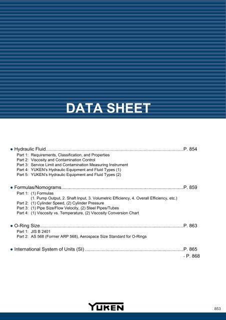
<strong>DATA</strong> <strong>SHEET</strong><br />
● Hydraulic Fluid...........................................................................................................................P. 854<br />
Part 1: Requirements, Classification, and Properties<br />
Part 2: Viscosity and Contamination Control<br />
Part 3: Service Limit and Contamination Measuring Instrument<br />
Part 4: YUKEN’s Hydraulic Equipment and Fluid Types (1)<br />
Part 5: YUKEN’s Hydraulic Equipment and Fluid Types (2)<br />
● Formulas/Nomograms.............................................................................................................P. 859<br />
Part 1: (1) Formulas<br />
(1. Pump Output, 2. Shaft Input, 3. Volumetric Efficiency, 4. Overall Efficiency, etc.)<br />
Part 2: (1) Cylinder Speed, (2) Cylinder Pressure<br />
Part 3: (1) Pipe Size/Flow Velocity, (2) Steel Pipes/Tubes<br />
Part 4: (1) Viscosity vs. Temperature, (2) Viscosity Conversion Chart<br />
● O-Ring Size................................................................................................................................P. 863<br />
Part 1: JIS B 2401<br />
Part 2: AS 568 (Former ARP 568), Aerospace Size Standard for O-Rings<br />
● International System of Units (SI) ........................................................................................P. 865<br />
- P. 868<br />
853
Hydraulic Fluid [Part 1]<br />
Requirements, Classification, and<br />
Properties<br />
Data Sheet<br />
■ Requirements<br />
Hydraulic pumps, control valves, and hydraulic cylinders operate at high pressure and high speed; they are also constructed of a<br />
variety of materials. Considering these facts as well as fluid temperature and ambient conditions during operation, the following<br />
requirements for hydraulic fluids must be met.<br />
● Maintaining proper viscosity as temperature ● Highly oxidation stable ● Rust-preventive<br />
changes ● Highly shear stable ● Non-compressible<br />
● Flowable at low temperature ● Non-corrosive to metal ● Providing good defoaming<br />
● Resistant to high temperature degradation ● Exhibiting good demulsibility/water performance<br />
● Providing high lubricity and wear resistance separation when mixed with water ● Fire-resistant<br />
粘 度 範 囲 於 40<br />
■ Classification<br />
JIS standards for hydraulic fluids do not currently exist, and fluids that meet the above requirements and have a viscosity<br />
equivalent to that of petroleum based turbine oils (JIS K 2213) are used. Turbine oils are classified into two types: Type 1<br />
(without additives) and Type 2 (with additives). Type 2 turbine oils contain antirust, antioxidant, and other additives. JIS K 2213<br />
Type 2 turbine oils and special oils with a viscosity grade of ISO VG 32, 46, or 68 are widely used. If there is a risk of fire in the<br />
event of fluid leakage or blowout from hydraulic systems, fire-resistant synthetic or water containing fluids are employed. These<br />
fire-resistant fluids have different properties from petroleum base oils and must be handled carefully in practical applications.<br />
Chlorinated hydrocarbon fluids are rarely used for industrial purposes in Japan, since they become highly toxic and corrosive<br />
when decomposed. While other fluids are also available, fluids used for general industrial purposes are largely categorized as<br />
follows.<br />
Petroleum Base<br />
Oil<br />
R&O Type Oil<br />
Additive Turbine Oil<br />
Special Oil<br />
Anti-Wear Type Hydraulic Oil<br />
High Viscosity Index Hydraulic Oil<br />
Low Temperature Hydraulic Oil<br />
High Temperature Hydraulic Oil<br />
Hydraulic Fluid<br />
Synthetic Fluid<br />
(Fire-Resistant)<br />
Water<br />
Containing Fluid<br />
(Fire-Resistant)<br />
Phosphate Ester Fluid<br />
Polyol Ester Fluid<br />
Chlorinated Hydrocarbon Fluid<br />
Water-Glycol Fluid<br />
Water-In-Oil (W/O) Emulsion<br />
Oil-In-Water (O/W) Emulsion<br />
■ Properties (Example)<br />
Item<br />
Specific Gravity<br />
(15/4 °C)<br />
Viscosity<br />
(mm 2 /s)<br />
Hydraulic<br />
Fluid<br />
40 °C<br />
100 °C<br />
Petroleum Base<br />
Oil (Type 2<br />
Turbine Oil<br />
Equivalent to<br />
ISO VG 32)<br />
Phosphate<br />
Ester Fluid<br />
Polyol Ester<br />
Fluid<br />
Water-Glycol<br />
Fluid<br />
W/O<br />
Emulsion<br />
O/W<br />
Emulsion<br />
0.87 1.13 0.93 1.04 - 1.07 0.93 1.00<br />
32.0<br />
5.4<br />
41.8<br />
5.2<br />
Viscosity Index (VI) 100 20 160 146 140 -<br />
Max. Operating<br />
Temp. (ºC)<br />
70 100 100 50 50 50<br />
Min. Operating<br />
Temp. (ºC)<br />
-10 -20 -5 -30 0 0<br />
Strainer Resistance 1.0 1.03 1.0 1.2 0.7 - 0.8<br />
(Same As<br />
Water)<br />
40.3<br />
8.1<br />
38.0<br />
7.7<br />
95.1<br />
-<br />
0.7<br />
-<br />
854<br />
Data Sheet
Hydraulic Fluid [Part 2]<br />
Viscosity and Contamination Control<br />
Data Sheet<br />
■ Viscosity<br />
The viscosity of industrial lubricants, including hydraulic fluids, is measured by kinematic viscosity v [m 2 /s], which is obtained by<br />
dividing absolute viscosity by density. It is typically expressed in units of square millimeters per second (mm 2 /s). For viscosity<br />
measurement, a capillary viscometer is used to determine kinematic viscosity (mm 2 /s) as per JIS K 2283 “Crude petroleum and<br />
petroleum products - Determination of kinematic viscosity and calculation of viscosity index from kinematic viscosity”. Hydraulic<br />
fluid viscosity critically affects the performance of hydraulic systems. System operation with a hydraulic fluid viscosity outside the<br />
specified range may result in pump suction failure, internal leakage, poor lubrication, valve malfunction, or heat generation in the<br />
circuit, shortening the life of equipment or causing a major accident.<br />
According to JIS K 2001 “Industrial liquid lubricants - ISO viscosity classification”, 20 viscosity grades are available ranging from<br />
ISO VG 2 to 3200. The figure below shows the viscosity range associated with the operation of hydraulic systems. For details,<br />
see “Viscosity vs. Temperature” on page 862.<br />
Viscosity Range (at 40 ºC)<br />
Kinematic Viscosity [mm 2 /s]<br />
ISO Viscosity<br />
Grade (ISO VG)<br />
★ For JIS K 2213 Type 2 (with additives), three grades ISO<br />
VG 32, 46, and 68 are available.<br />
■ Contamination control<br />
● Cleanliness<br />
Hydraulic fluid replacement is required in the following three cases.<br />
(a) Deterioration or degradation of the fluid<br />
(b) Particulate contamination of the fluid<br />
(c) Water contamination of the fluid<br />
While Table 3 provides guidelines for (a), the necessity of hydraulic fluid replacement is caused by (b) and (c) in most cases.<br />
Particulate contamination of hydraulic fluids may result in pump wear or valve malfunction. In particular, the performance of<br />
systems equipped with precision valves (e.g. electro-hydraulic servo valves) and actuators is adversely affected by fine particles of<br />
a few micrometers to a few tens of micrometers. Thus, it is necessary to control the level of contamination properly by measuring<br />
the size and number of particles in the fluid with a microscope or by measuring the mass of particles per unit volume of the fluid.<br />
For the determination of the fluid cleanliness level, filter 100 ml of the fluid through a filtration device and collect particles on a<br />
millipore filter (a filter with fine pores of 1/1000 mm). Measure the number and size of the collected particles for classification as<br />
shown in Table 1. For highly contaminated fluids, determine the cleanliness level based on the mass of particles collected on the<br />
millipore filter, as shown in Table 2. Unused R&O type oils have a cleanliness level of Class 6 to 8 shown in Table 1.<br />
Table 1 NAS Cleanliness Level Based on Particle Counting<br />
Number of particles per 100 ml<br />
Size<br />
Class (NAS 1638)<br />
(μm) 00 0 1 2 3 4 5 6 7 8 9 10 11 12<br />
5 - 15 125 250 500 1,000 2,000 4,000 8,000 16,000 32,000 64,000 128,000 256,000 512,000 1,024,000<br />
15 - 25 22 44 89 178 356 712 1,425 2,850 5,700 11,400 22,800 45,600 91,000 182,400<br />
25 - 50 4 8 16 32 63 126 253 506 1,012 2,025 4,050 8,100 16,200 32,400<br />
50 - 100 1 2 3 6 11 22 45 90 180 360 720 1,440 2,880 5,760<br />
More<br />
0 0 1 1 2 4 8 16 32 64 128 256 512 1,024<br />
than 100<br />
NAS: National Aerospace Standard ISO: International Organization for Standardization<br />
Data<br />
Sheet<br />
Table 2 Classification Based on the Gravimetric Method<br />
NAS<br />
Class 100 101 102 103 104 105 106 107 108<br />
mg/100 ml 0.02 0.05 0.10 0.3 0.5 0.7 1.0 2.0 4.0<br />
Class A B C D E F G H I<br />
MIL<br />
Less<br />
7.0 - 10.0 - 15.0 -<br />
mg/100 ml<br />
1.0 - 2.0 2.0 - 3.0 3.0 - 4.0 4.0 - 5.0 5.0 - 7.0<br />
than 1.0<br />
10.0 15.0 25.0<br />
MIL: Military Specifications and Standards<br />
Hydraulic Fluid<br />
Data Sheet 855
Hydraulic Fluid [Part 3]<br />
Service Limit and<br />
Contamination Measuring Instrument<br />
Data Sheet<br />
● Service limit<br />
Unused R&O type oils contain 50 to 80 ppm (0.005 to 0.008%) of<br />
water, but the water content increases due to entry of atmospheric<br />
moisture through the actuator or air breather. Water may cause<br />
rust on the inside of hydraulic equipment, poor lubrication, or<br />
accelerated degradation of the hydraulic fluid. The water content<br />
of the fluid is measured by Karl Fischer titration (based on the<br />
quantitative reaction of the reagent with water) with a sensitivity of<br />
10 ppm. The particulate/water contamination tolerance of<br />
hydraulic fluids varies depending on the system configuration as<br />
outlined in Tables 4 and 5.<br />
Table 4 Recommended Control Level of Fluid Contamination<br />
System Configuration<br />
Class<br />
JIS B 9933<br />
(ISO 4406)<br />
System with Servo Valve 18/16/13 7<br />
System with Piston Pump 20/18/14 9<br />
System with Proportional Electro-Hydraulic<br />
Control Valve<br />
System Operating at Pressures Higher than<br />
21 MPa<br />
System Operating at Pressures of 14 to 21<br />
MPa<br />
NAS<br />
20/18/14 9<br />
20/18/14 9<br />
21/19/15 10<br />
General Low Pressure Hydraulic System 21/20/16 11<br />
★ Comparison of JIS B 9933 (ISO 4406) and NAS for reference<br />
Table 3 Criteria for Hydraulic Fluid Replacement (Example)<br />
Fluid Type<br />
Petroleum Base Oil<br />
Test Item R&O Anti-Wear<br />
Kinematic<br />
Viscosity (40 ºC) ★<br />
mm 2 /s<br />
Total Acid<br />
Number ★<br />
mgKOH/g<br />
0.25<br />
Water-Glycol<br />
Fluid<br />
±10% ±10%<br />
a ☆ 0.25<br />
b ☆ ±40%<br />
★: Variation in kinematic viscosity<br />
☆: Additive type (a: Non-zinc based, b: Zinc based)<br />
Table 3 provides guidelines for hydraulic fluid<br />
replacement. Detailed specifications vary depending<br />
on the manufacturer, and additional control<br />
requirements may be applied. Contacting the fluid<br />
manufacturer is recommended.<br />
For example, the total acid number (or acid number) is<br />
a measure of fluid degradation and affected by the<br />
additive type and level. For water-glycol fluids, the<br />
pH value is also controlled.<br />
-<br />
Table 5 Water Contamination Tolerance of R&O Type Oils 1 ppm = 1/1000000<br />
The hydraulic fluid is cloudy with water.<br />
System Conditions<br />
The system has a circuit for circulating the hydraulic fluid back to the oil tank and operates without long-term<br />
shutdown.<br />
The piping length of the system is long, and the hydraulic fluid does not fully circulate in the circuit.<br />
The system remains out of service for a long period (safety system), has a circuit in which the hydraulic fluid<br />
hardly moves, or is designed to provide precision control.<br />
Service Limit<br />
To be immediately<br />
replaced<br />
500 ppm<br />
300 ppm<br />
200 ppm<br />
● Portable Fluid Contamination Measuring Instrument<br />
CONTAMI-KIT<br />
Model Number: YC-100-22<br />
YUKEN’s CONTAMI-KIT is a fluid contamination measuring instrument that samples hydraulic fluids<br />
and microscopically measures the distribution of particles collected on a membrane filter as per JIS<br />
B 9930 or SAE ARP 598 A.<br />
■ Specifications<br />
1) Power supply: Both AC and DC power supplies supported (100 V AC/6 V DC)<br />
2) Microscope magnification: 100 times (40 times: Option for KYC-100-L-20)<br />
3) Applicable fluids: Petroleum base oil, polyol ester fluid, and water-glycol fluid (optional)<br />
4) Case dimensions: L 600 × W 240 × H 360 mm<br />
5) Total mass: Approximately 9 kg<br />
■ Features of CONTAMI-KIT<br />
1) Usable everywhere<br />
Portable and supports both AC and DC power supplies (switchable).<br />
2) User-friendly<br />
Requires no skills and involves only comparing the results with the standard contamination plate.<br />
3) Time-efficient<br />
Takes only about 10 minutes for each measurement.<br />
4) Supporting photo taking<br />
Allows photo taking with a single-lens reflex camera for recording.<br />
Sample Standard<br />
Contamination Plate<br />
856<br />
Data Sheet
Hydraulic Fluid [Part 4]<br />
YUKEN’s Hydraulic Equipment<br />
and Fluid Types (1)<br />
Data Sheet<br />
Hydraulic equipment is affected differently depending on the fluid type; special care should be taken when selecting the equipment.<br />
The table below shows YUKEN’s hydraulic equipment available for each fluid type. For details, see the relevant pages.<br />
Hydraulic Fluid<br />
Equipment<br />
A Series Variable<br />
Displacement Piston<br />
Pump<br />
Fixed Displacement<br />
Vane Pump<br />
Pressure Control Valve<br />
Flow Control Valve<br />
Directional Control Valve<br />
Cylinder<br />
Seal<br />
Modular Valve<br />
Logic Valve<br />
Proportional<br />
Electro-Hydraulic<br />
Control valve<br />
Servo Valve<br />
CJT Series<br />
CBY14 Series<br />
Accumulator<br />
Needle Valve<br />
Petroleum Base Oil<br />
(Equivalent to JIS K 2213 Type 2)<br />
Standard<br />
Standard<br />
Standard<br />
Standard<br />
Standard<br />
Standard<br />
Standard<br />
Standard<br />
Standard<br />
Standard<br />
Standard<br />
Packing Material: 6 (HNBR)<br />
Standard/<br />
Commercially Available<br />
Product<br />
Standard<br />
Phosphate Ester Fluid<br />
Custom: Z6<br />
Seal: Fluororubber<br />
“F-” + Standard Model<br />
Seal: Fluororubber<br />
“F-” + Standard Model<br />
Seal: Fluororubber<br />
“F-” + Standard Model<br />
Seal: Fluororubber<br />
“F-” + Standard Model<br />
Seal: Fluororubber<br />
“F-” + Standard Model<br />
Seal: Fluororubber<br />
“F-” + Standard Model<br />
Seal: Fluororubber<br />
“F-” + Standard Model ★ 1<br />
Seal: Fluororubber<br />
“F-” + Standard Model<br />
Seal: Fluororubber<br />
“F-” + Standard Model<br />
Seal: Fluororubber<br />
Semi-Standard<br />
Packing Material: 3<br />
(Fluororubber)<br />
Butyl Rubber Diaphragm Type/<br />
Piston Type (Except for<br />
Aluminum) Permitted<br />
“F-” + Standard Model<br />
Seal: Fluororubber<br />
Polyol Ester Fluid<br />
Consult us.<br />
Standard<br />
Standard<br />
Standard<br />
Standard<br />
Standard<br />
Standard<br />
Standard ★ 2<br />
Standard<br />
Standard<br />
Standard<br />
Packing Material: 6 (HNBR)<br />
Butyl Rubber Diaphragm Type<br />
Prohibited<br />
Standard<br />
Tank Filter Aluminum Aluminum Aluminum<br />
Oil Level Gauge Direct Reading Type Remote Reading Type Direct Reading Type<br />
Rubber Tube Nitrile Rubber Butyl Rubber Nitrile Rubber<br />
Inside Coating of<br />
Oil Tank<br />
Effect on Metals<br />
Epoxy/Phenolic Coating<br />
Permitted<br />
None<br />
Inside Coating Prohibited<br />
(Chemical Conversion Coating<br />
Permitted)<br />
Aluminum Sliding Parts<br />
Phenolic Coating Prohibited<br />
Prohibited<br />
Nitrile Rubber Permitted Prohibited Permitted<br />
Fluororubber Permitted Permitted Permitted<br />
Silicone Rubber Prohibited Permitted Permitted<br />
Butyl Rubber Prohibited Permitted Prohibited<br />
Ethylene Propylene<br />
None<br />
Prohibited Permitted Permitted<br />
Rubber<br />
Urethane Rubber Permitted Prohibited Permitted<br />
Fluororesin Permitted Permitted Permitted<br />
Chloroprene Permitted Prohibited Permitted<br />
Leather Permitted Permitted Permitted<br />
Other -<br />
Protect electrical wiring by<br />
applying oil resistant coating or<br />
by running it in conduits.<br />
-<br />
★1. Contact us for details of EH Series High Response Directional and Flow Control Valves (EHDFG-04/06).<br />
★2. Contact us for details of EH Series Directional and Flow Control Valves (EHDFG-03) and EH Series High Response Directional and<br />
Flow Control Valves (EHDFG-04/06).<br />
Data<br />
Sheet<br />
Hydraulic Fluid<br />
Data Sheet 857
Hydraulic Fluid [Part 5]<br />
YUKEN’s Hydraulic Equipment<br />
and Fluid Types (2)<br />
Data Sheet<br />
Hydraulic Fluid<br />
Equipment<br />
A Series Variable<br />
Displacement Piston<br />
Pump<br />
Fixed Displacement<br />
Vane Pump<br />
Water-Glycol Fluid W/O Emulsion O/W Emulsion<br />
Custom: Z30 Custom: Z30 Consult us.<br />
“M-” + Standard Model<br />
PV2R: Standard<br />
Custom: Z35<br />
(“M-” + Standard Model in<br />
some cases)<br />
PV2R: Standard<br />
Consult us.<br />
Pressure Control Valve Standard Consult us. Consult us.<br />
Cylinder<br />
Seal<br />
Flow Control Valve Standard Consult us. Consult us.<br />
Directional Control<br />
Valve<br />
Standard Standard Consult us.<br />
Modular Valve Standard Consult us. Consult us.<br />
Logic Valve Standard Consult us. Consult us.<br />
Proportional<br />
Electro-Hydraulic<br />
Control Valve<br />
Standard ★ 1<br />
Servo Valve Standard ★ 2<br />
CJT Series<br />
CBY14 Series<br />
Accumulator<br />
Standard<br />
Seal: Nitrile Rubber<br />
Standard<br />
Packing Material: 6 (HNBR)<br />
Standard/<br />
Commercially Available Product<br />
Consult us.<br />
Consult us.<br />
Standard<br />
Seal: Nitrile Rubber<br />
Standard<br />
Packing Material: 6 (HNBR)<br />
Standard/<br />
Commercially Available Product<br />
Consult us.<br />
Consult us.<br />
Custom<br />
Seal: Nitrile Rubber<br />
Standard<br />
Packing Material: 6 (HNBR)<br />
Standard/<br />
Commercially Available Product<br />
Needle Valve Standard Standard Standard<br />
Tank Filter<br />
Stainless Steel<br />
(Aluminum, Cadmium, or<br />
Galvanizing Prohibited)<br />
Aluminum/Stainless Steel<br />
(Cadmium or Galvanizing<br />
Prohibited)<br />
Stainless Steel<br />
(Aluminum Prohibited)<br />
Oil Level Gauge Direct Reading Type Direct Reading Type Direct Reading Type<br />
Rubber Tube Nitrile Rubber Nitrile Rubber Nitrile Rubber<br />
Inside Coating of<br />
Oil Tank<br />
Effect on Metals<br />
Inside Coating Prohibited<br />
(Chemical Conversion Coating<br />
Permitted)<br />
Aluminum, Cadmium, or Zinc<br />
Prohibited<br />
Inside Coating Prohibited<br />
(Chemical Conversion Coating<br />
Permitted)<br />
Copper, Cadmium, or Zinc<br />
Prohibited<br />
Epoxy Coating Permitted<br />
Nitrile Rubber Permitted Permitted Permitted<br />
Fluororubber Permitted Permitted Permitted<br />
Silicone Rubber Prohibited Prohibited Prohibited<br />
Butyl Rubber Permitted Prohibited Prohibited<br />
Ethylene<br />
Propylene Rubber<br />
Permitted Prohibited Prohibited<br />
Urethane Rubber Prohibited Prohibited Prohibited<br />
Fluororesin Permitted Permitted Permitted<br />
Chloroprene Permitted Permitted Permitted<br />
Leather Prohibited Prohibited Prohibited<br />
Be sure to have the oil tank<br />
Other -<br />
bottom tilted and equipped with<br />
-<br />
a drain cock.<br />
★1. Contact us for details of EH Series High Response Directional and Flow Control Valves (EHDFG-04/06).<br />
★2. Contact us for details of the following products.<br />
- On-Board Electronics Type Linear Servo Valves without DR Port (Wet Type Pilot Valve: LSVHG-*EH-*-W)<br />
None<br />
858<br />
Data Sheet
Formulas/Nomograms [Part 1]<br />
(1) Formulas<br />
Data Sheet<br />
SI Unit<br />
Engineering Unit (Reference)<br />
Hydraulic Pump<br />
Hydraulic Power<br />
(Pump Output)<br />
Shaft Input<br />
L O : Hydraulic Power kW<br />
P: Pressure MPa<br />
Q: Flow L/min<br />
* 1 kW = 1 kN•m/s<br />
= 60 kN•m/min<br />
L i : Shaft Input kW<br />
T: Shaft Torque N•m<br />
N: Shaft Speed r/min<br />
Volumetric Efficiency η V : Volumetric Efficiency %<br />
Q P : Flow at Pressure P L/min<br />
Q O : Flow at No Load L/min<br />
* Q O - Q P = Pump’s Total Internal Leakage<br />
Overall Efficiency η: Overall Efficiency %<br />
L O : Hydraulic Power kW<br />
L i : Shaft Input kW<br />
P: Discharge Pressure MPa<br />
Q: Flow L/min<br />
Hydraulic Motor Output<br />
L: Output kW<br />
T: Torque Nm<br />
N: Speed r/min<br />
L O : Hydraulic Power kW<br />
P: Pressure kgf/cm 2<br />
Q: Flow L/min<br />
* 1 kW = 102 kgf•m/s<br />
= 6120 kgf•m/min<br />
L i : Shaft Input kW<br />
T: Shaft Torque kgf•m<br />
N: Shaft Speed rpm<br />
η: Overall<br />
Efficiency %<br />
L O : Hydraulic Power kW<br />
L i : Shaft Input kW<br />
P: Discharge Pressure kgf/cm 2<br />
L: Output kW<br />
T: Torque kgf•m<br />
N: Speed rpm<br />
Cylinder Output<br />
Valve Power Loss<br />
Flow Q<br />
Pressure P 1 Pressure P 2<br />
Valve<br />
L: Output kW<br />
F: Force kN<br />
V: Speed m/min<br />
L: Output kW<br />
F: Force kgf<br />
V: Speed m/min<br />
Pressure Loss:<br />
Power Loss between Valve Inlet and Outlet: L<br />
Viscosity (Absolute) and<br />
Kinematic Viscosity<br />
μ: Viscosity (Absolute) Pa•s (= N•s/m 2 )<br />
ρ: Density kg/m 3<br />
ν 1 : Kinematic Viscosity m 2 /s<br />
ν 2 : Kinematic Viscosity mm 2 /s<br />
μ: Viscosity (Absolute) kgf·s/cm 2<br />
ρ: Density kgf·s 2 /cm 4<br />
ν 1 : Kinematic Viscosity cm 2 /s<br />
ν 2 : Kinematic Viscosity cSt<br />
γ: Specific Gravity kgf/cm 3<br />
g: Gravitational Acceleration 980 cm/s 2<br />
* 1 cSt = 0.01 cm 2 /s<br />
Diameter d<br />
Reynolds Number<br />
Velocity V<br />
Flow Q<br />
Dimensionless<br />
Quantity<br />
R: Reynolds Number<br />
ν: Kinematic Viscosity<br />
Orifice Flow<br />
* R < 2300: Laminar Flow<br />
R > 2300: Turbulent Flow<br />
Data<br />
Sheet<br />
A: Opening Area<br />
ΔP = P 1 - P 2<br />
C = Discharge Coefficient<br />
γ = Specific Gravity<br />
ρ = Density<br />
Q: L/min ρ: kg/m 3<br />
Q: L/min g: 980 cm/s 2<br />
C: Dimensionless<br />
C: Dimensionless Discharge<br />
Discharge Coefficient<br />
Coefficient<br />
ΔP: MPa A: cm 2 γ: kgf/cm 3 A: cm 2<br />
ΔP: kgf/cm 2<br />
Note) The value of discharge coefficient depends on the flow channel geometry and<br />
the Reynolds number; it generally ranges from 0.6 to 0.9.<br />
Formulas/Nomograms<br />
Data Sheet 859
Formulas/Nomograms [Part 2]<br />
(1) Cylinder Speed, (2) Cylinder Pressure<br />
Data Sheet<br />
Force<br />
Determination of Cylinder Pressure<br />
The force value obtained from this chart<br />
assumes that the rod side pressure P<br />
and the packing resistance F0 are 0.<br />
Pressure<br />
Cylinder Size<br />
Area Inside Dia.<br />
Area A1 Area A2<br />
Force F1<br />
Pressure P1 Pressure P2<br />
Packing Resistance F0<br />
Unit<br />
Cylinder Size<br />
Area Inside Dia.<br />
Cylinder Speed<br />
Flow<br />
Area A1 Area A2<br />
Speed V1<br />
Flow Q1<br />
Flow Q2<br />
Unit<br />
Cylinder Speed<br />
860<br />
Data Sheet
Formulas/Nomograms [Part 3]<br />
(1) Pipe Size/Flow Velocity,<br />
(2) Steel Pipes/Tubes<br />
Data Sheet<br />
Pipe Size/<br />
Flow Velocity<br />
Flow<br />
Pipe Size<br />
Inside Area Inside Dia.<br />
Flow Velocity<br />
Nominal<br />
Pipe Size<br />
Reference Value<br />
of Velocity in<br />
Suction Pipe<br />
Reference Value<br />
of Velocity in<br />
Pressure Pipe<br />
2<br />
Steel Tubes/Pipes<br />
SGP. STS370. STPS2<br />
●Carbon Steel Pipes<br />
Pipe Type -><br />
SGP<br />
STS370<br />
(JIS G 3452)<br />
(JIS G 3455)<br />
Nominal Pres. MPa -> 2 4 6 10 16 25 35<br />
Safety Factor -> 8 or more 6 or more 5 or more 4 or more<br />
Nominal Dia. Outside Thickness Thick Sch. Thick Sch. Thick Sch. Thick Sch. Thick Sch. Thick Sch.<br />
(A) (B) mm mm mm No. mm No. mm No. mm No. mm No. mm No.<br />
8 1/4 13.8 3.0 80<br />
10 3/8 17.3 3.2 80<br />
15 1/2 21.7 2.8 40 3.7 80 4.7 160<br />
20 3/4 27.2 2.9 40 3.9 80 5.5 160<br />
25 1 34.0 3.4 40 4.5 80 6.4 160<br />
32 1 1/4 42.7 3.6 40 4.9 80 6.4 160 8.0 ★<br />
40 1 1/2 48.6 3.7 40 5.1 80 7.1 160 9.0 ★<br />
50 2 60.5 3.9 40 5.5 80 8.7 160 11.2 ★<br />
65 2 1/2 76.3 4.2 5.2 40 7.0 80 9.5 160 14.2 ★<br />
80 3 89.1 4.2 5.2 40 7.6 80 11.1 160 16.5 ★<br />
90 3 1/2 101.6 4.2 5.7 40 8.1 80 12.7 160 20.0 ★<br />
100 4 114.3 4.5 6.0 40 8.6 80 13.5 160 20.0 ★<br />
125 5 139.8 4.5 9.5 80 15.9 160<br />
150 6 165.2 5.0 11.0 80 18.2 160<br />
●Precision Carbon Steel Tubes for Compression Type Tube Fittings<br />
・Thickness (mm)<br />
Nominal Pres. MPa<br />
10 16 25 35<br />
Outside mm Safety Factor 6 or more 4 or more<br />
6 1.5<br />
10 1.5 2.0<br />
12 2.0 2.5<br />
16 2.0 3.0<br />
20 2.0 2.5 3.0<br />
25 2.5 4.0<br />
Note)<br />
Note)<br />
1. STPS2 defined in JIS B 2351-1 Annex 2.<br />
2. For selection considerations, refer to Note 1 in the “Carbon<br />
Steel Pipes” section.<br />
3. Designation<br />
(Example) STPS2-12 × 2.5<br />
1. The selection of steel pipes based on<br />
the operating pressure may be difficult,<br />
since the pressure fluctuation, pipe<br />
vibration, pipe connection type, and<br />
other factors must be considered.<br />
Refer to the nominal pressure values<br />
and their corresponding safety factors<br />
in the left table for pipe selection.<br />
2. “Sch. No.” is an abbreviation for<br />
schedule number. Note that “★”<br />
indicates special thick wall steel pipes<br />
with no schedule number.<br />
<br />
JIS G 3452, 3454 to 64<br />
Description<br />
Schedule number = 10 × P/S<br />
where<br />
P: Operating pressure MPa<br />
S: Allowable stress MPa<br />
3. Designation (-B Series of Yuken)<br />
(Example 1)<br />
SGP pipe: SGP-2 1/2B<br />
(Example 2)<br />
STS370 with Sch. No.:<br />
STS370-3/4B × Sch. 80<br />
(Example 3)<br />
STS370 special thick wall steel pipe:<br />
STS370-1 1/4B × 8.0 t<br />
Data<br />
Sheet<br />
Formulas/Nomograms<br />
Data Sheet 861
Formulas/Nomograms [Part 4]<br />
(1) Viscosity vs. Temperature,<br />
(2) Viscosity Conversion Chart<br />
Data Sheet<br />
Viscosity vs.<br />
Temperature<br />
Viscosity<br />
Fluid Viscosity<br />
Grade<br />
(ISO-VG*)<br />
Temperature<br />
Viscosity Conversion Chart<br />
Use the following equations when<br />
the viscosity is 100 mm 2 /s or more.<br />
SSU × 0.220 = mm 2 /s<br />
RSS × 0.2435 = mm 2 /s<br />
°E × 7.6 = mm 2 /s<br />
Square Millimeters Per Second (mm 2 /s)<br />
Saybolt Universal Seconds (SSU)<br />
Redwood No. 1 Seconds (RSS)<br />
(Ex.)<br />
Engler Degrees (°E)<br />
Square Millimeters Per Second (mm 2 /s)<br />
862<br />
Data Sheet
O-Ring Size [Part 1]<br />
JIS B 2401<br />
Data Sheet<br />
O-Ring Types According to JIS and YES (Yuken Engineering Standards)<br />
Remarks<br />
For Use with<br />
Mineral Oils<br />
Material:<br />
Nitrile Rubber<br />
Spring Hardness: 70<br />
Spring Hardness: 90<br />
Designation<br />
Actual Size (mm)<br />
For Use with Heat<br />
Resistant/Synthetic<br />
Oils<br />
Material:<br />
Fluororubber<br />
Note) 1. “-P*” denotes dynamic O-rings; “-G*” denotes static O-rings.<br />
2. The basic sizes for -1A, -1B, and -4D are the same.<br />
Spring Hardness: 70<br />
Spring Hardness: 90<br />
Designation<br />
Actual Size (mm)<br />
Designation<br />
Actual Size (mm)<br />
Data<br />
Sheet<br />
O-Ring Size<br />
Data Sheet 863
O-Ring Size [Part 2]<br />
AS 568 (Former ARP 568),<br />
Aerospace Size Standard for O-Rings<br />
Data Sheet<br />
Designation<br />
Actual Size (mm) Actual Size (mm) Actual Size (mm)<br />
Designation<br />
Designation<br />
Designation<br />
Actual Size (mm)<br />
Designation<br />
Actual Size (mm)<br />
864<br />
Data Sheet
International System of Units (SI) [Part 1]<br />
(According to JIS Z 8203 “SI units and recommendations for the<br />
use of their multiples and of certain other units” and Z 8202<br />
“Quantities and units”)<br />
Data Sheet<br />
■ Origin of the term SI (International System of Units)<br />
SI stands for Système International d'Unités in French (International System of Units in English), an internationally accepted<br />
official abbreviation.<br />
■ Purpose and historical background of the SI<br />
The Metre Convention was signed in 1875 to oversee the keeping of metric system as a unified international system of units.<br />
Then, the metric system had more than ten variations, losing its consistency. At the 9th General Conference on Weights and<br />
Measures (Conférence Générale des Poids et Mesures: CGPM) in 1948, a resolution was adopted “to use a unified system of<br />
units in all fields”. The International Committee for Weights and Measures (Comité International des Poids et Mesures: CIPM) of<br />
the treaty organization started a process to establish a unified system and determined the framework of the SI in 1960. In 1973,<br />
the International Organization for Standardization (ISO) developed the standard ISO 1000, which describes SI units and<br />
recommendations for the use of them, leading to global adoption of the system. In Japan, a policy to introduce SI units into JIS<br />
through the following three phases was determined in 1972; the introduction of SI units into JIS progressed rapidly.<br />
First phase: Use of conventional units followed by SI units e.g. 1 kgf [9.8 N]<br />
Second phase: Use of SI units followed by conventional units e.g. 10 N {1.02 kgf}<br />
Third phase: Use of SI units only<br />
e.g. 10 N<br />
The Measurement Act in Japan was fully revised in 1992 and enacted in 1993 to unify statutory measurement units into SI units.<br />
Under the new Measurement Act, a transition period of up to seven years was granted before the exclusive use of SI units for<br />
“pressure” and “moment of force” in the field of hydraulics, and the period expired on September 30, 1999. Since October 1,<br />
1999, it has been mandatory to use SI units as statutory measurement units for transactions and certifications. Commercially<br />
available pressure gauges are in SI units. The units used in this catalogue are SI units.<br />
All units used in this catalogue are SI units as applicable in the third phase of the SI implementation process.<br />
■ Structure of SI units and JIS Z 8203<br />
Base Units (7)<br />
SI Units<br />
Supplementary Units (2)<br />
Derived Units with Special Names (19)<br />
Derived<br />
Units<br />
Other Derived Units<br />
Prefixes (20) and Decimal Multiples of SI units<br />
Important Non-SI Units Accepted for Use with SI Units<br />
Base Units<br />
Supplementary Units<br />
Quantity<br />
Base Unit<br />
Name<br />
Symbol<br />
Quantity<br />
Supplementary Unit<br />
Name Symbol<br />
Length<br />
meter<br />
Plane Angle<br />
radian<br />
Mass<br />
kilogram<br />
Solid Angle<br />
steradian<br />
Time<br />
Electric Current<br />
Thermodynamic<br />
Temperature<br />
Amount of<br />
Substance<br />
Luminous<br />
Intensity<br />
second<br />
ampere<br />
kelvin<br />
mole<br />
candela<br />
Data<br />
Sheet<br />
International System<br />
of Units (SI)<br />
Data Sheet 865
International System of Units (SI)<br />
[Part 2]<br />
Data Sheet<br />
Prefixes<br />
Prefixes are used to form decimal multiples of SI units.<br />
Unit Multiplier<br />
Name<br />
Prefix<br />
Non-SI units accepted for use with SI units<br />
Quantity<br />
Time<br />
Plane<br />
Angle<br />
Volume<br />
Mass<br />
● Units accepted for use with SI units for<br />
usefulness in special fields<br />
Symbol<br />
The letter “L” may be used as the symbol for liter, when<br />
the symbol “l” for liter might be confused with any other<br />
character (as a general rule, Yuken uses “L”).<br />
Quantity<br />
Energy<br />
Atomic Mass<br />
Distance<br />
Fluid Pressure<br />
yotta<br />
zetta<br />
exa<br />
peta<br />
tera<br />
giga<br />
mega<br />
kilo<br />
hecto<br />
deka<br />
deci<br />
centi<br />
milli<br />
micro<br />
nano<br />
pico<br />
femto<br />
atto<br />
zepto<br />
yocto<br />
Unit Name<br />
minute<br />
hour<br />
day<br />
degree<br />
minute<br />
second<br />
liter<br />
metric ton<br />
Unit Name<br />
electronvolt<br />
atomic mass unit<br />
astronomical unit<br />
parsec<br />
bar<br />
Unit Symbol<br />
Unit Symbol<br />
Derived units<br />
Derived units are expressed algebraically in terms of base units and<br />
supplementary units (by means of the mathematical symbols of<br />
multiplication and division) in the International System of Units.<br />
Derived units expressed in terms of SI base units<br />
Quantity<br />
Derived units with special names<br />
Quantity<br />
Name<br />
Derived Unit<br />
Derived Unit<br />
Symbol<br />
Area square meter m 2<br />
Volume cubic meter m 3<br />
Speed, Velocity meter per second m/s<br />
Acceleration meter per second squared m/s 2<br />
Wavenumber reciprocal meter m -1<br />
Density kilogram per cubic meter kg/m 3<br />
Current Density ampere per square meter A/m 2<br />
Magnetic Field<br />
Strength<br />
ampere per meter<br />
A/m<br />
(Amount-of-substance)<br />
Concentration mole per cubic meter mol/m 3<br />
Specific Volume cubic meter per kilogram m 3 /kg<br />
Luminance candela per square meter cd/m 2<br />
Name Symbol Definition<br />
Frequency hertz Hz s -1<br />
Force newton N kg・m/s 2<br />
Pressure, Stress pascal Pa N/m 2<br />
Energy, Work, Amount of Heat joule J N・m<br />
Amount of Work Done Per<br />
Time, Motive Power, Electrical watt W J/s<br />
Power<br />
Electric Charge, Amount of<br />
Electricity coulomb C A・s<br />
Electric Potential, Potential<br />
Difference, Voltage,<br />
Electromotive Force<br />
volt V W/A<br />
Capacitance farad F C/V<br />
Electric Resistance ohm Ω V/A<br />
(Electric) Conductance siemens S A/V<br />
Magnetic Flux weber Wb V・s<br />
Magnetic Flux Density,<br />
Magnetic Induction tesla T Wb/m 2<br />
Inductance henry H Wb/A<br />
Celsius Temperature degree celsius/degree ºC<br />
Luminous Flux lumen lm cd・sy<br />
Illuminance lux lx lm/m 2<br />
Activity Referred to a<br />
Radionuclide becquerel Bq S -1<br />
Absorbed Dose gray Gy J/kg<br />
Dose Equivalent sievert Sv Gy<br />
866<br />
Data Sheet
International System of Units (SI)<br />
[Part 3]<br />
Data Sheet<br />
■ Use of SI units<br />
Space and Time<br />
Dynamics<br />
Heat<br />
Quantity<br />
SI Unit<br />
Decimal<br />
Multiple<br />
Unit<br />
Quantity<br />
SI Unit<br />
Decimal<br />
Multiple<br />
Unit<br />
Quantity<br />
SI Unit<br />
Decimal<br />
Multiple<br />
Unit<br />
Plane Angle<br />
Solid Angle<br />
rad<br />
(radian)<br />
sr<br />
(steradian)<br />
Density,<br />
Concentration<br />
kg/m 3<br />
(kilogram<br />
per cubic<br />
meter)<br />
mg/m 3 or<br />
kg/dm 3 or<br />
g/cm 3<br />
Thermodynamic<br />
Temperature<br />
Celsius<br />
Temperature<br />
Temperature Interval,<br />
Temperature Difference<br />
K (kelvin)<br />
ºC (degree<br />
Celsius or<br />
degree)<br />
K or ºC<br />
Length, Width,<br />
Height,<br />
Thickness,<br />
Radius,<br />
Diameter,<br />
Length of Path<br />
Traveled,<br />
Distance<br />
m<br />
(meter)<br />
Area m 2<br />
(square<br />
meter)<br />
Volume m 3<br />
(cubic meter)<br />
Moment of<br />
Inertia<br />
Force<br />
Moment of<br />
Force<br />
kg·m 2<br />
(kilogram<br />
meter<br />
squared)<br />
N (newton)<br />
N·m<br />
(newton<br />
meter)<br />
Amount of<br />
Heat<br />
Heat Flow<br />
Rate<br />
Thermal<br />
Conductivity<br />
Coefficient of Heat<br />
Transfer<br />
Specific Heat Capacity<br />
Electricity and Magnetism<br />
Electric<br />
Current<br />
J (joule)<br />
W (watt)<br />
A (ampere)<br />
Time<br />
s (second)<br />
Pressure<br />
Pa (pascal)<br />
Angular<br />
Velocity<br />
rad/s<br />
(radian per<br />
second)<br />
Speed, Velocity m/s<br />
(meter per<br />
second)<br />
Acceleration m/s 2<br />
(meter per<br />
second<br />
squared)<br />
Stress<br />
(pascal or<br />
newton per<br />
square<br />
meter)<br />
Pa or N/m 2<br />
GPa,<br />
MPa or<br />
N/mm 2 ,<br />
kPa<br />
Electric Potential,<br />
Electric Potential<br />
Difference,<br />
Voltage,<br />
Electromotive<br />
Force<br />
(Electric)<br />
Resistance<br />
(Direct<br />
Current)<br />
V (volt)<br />
(Remarks) MΩ<br />
is also referred<br />
to as megohm.<br />
Periodic and Related Phenomena<br />
Frequency<br />
Rotational<br />
Speed,<br />
Revolutions<br />
Dynamics<br />
Mass<br />
Hz (hertz)<br />
s -1<br />
(per second)<br />
kg<br />
(kilogram)<br />
Viscosity<br />
Kinematic<br />
Viscosity<br />
Work, Energy,<br />
Amount of<br />
Heat<br />
Power, Amount<br />
of Work Done<br />
Per Unit of<br />
Time<br />
Flow Rate<br />
Pa·s<br />
(pascal<br />
second)<br />
m 2 /s<br />
(square meter<br />
per second)<br />
J (joule)<br />
W (watt)<br />
m 3 /s<br />
(cubic meter<br />
per second)<br />
(Active)<br />
Electric<br />
Power<br />
Sound<br />
Frequency<br />
Ω (ohm)<br />
W (watt)<br />
Hz (hertz)<br />
Sound Pressure Level*<br />
* This SI unit is not provided by ISO<br />
1000-1973 and ISO 31 Part 7-1978, but<br />
JIS adopts and specifies dB (decibel) as<br />
a unit accepted for use with SI units.<br />
Data<br />
Sheet<br />
International System<br />
of Units (SI)<br />
Data Sheet 867
International System of Units (SI)<br />
[Part 4]<br />
Data Sheet<br />
■ SI unit conversion factors table<br />
(Shaded columns<br />
represent SI units.)<br />
Force<br />
N<br />
Newton<br />
Moment of inertia<br />
N·m<br />
Newton meter<br />
Note) 1 N·m = 1 kg•m 2 /s 2<br />
Pressure<br />
Pa<br />
pascal<br />
mmHg or Torr<br />
Note) 1 Pa = 1 N/m 2<br />
Stress<br />
Pa<br />
pascal<br />
MPa or N/mm 2<br />
Megapascal or<br />
newton per square milimeter<br />
Viscosity<br />
Pa•s<br />
pascal second<br />
Note) 1 P = 1 dyn•s/cm 2 = 1 g/cm•s<br />
Note) 1 Pa•s = 1 N•s/m 2 , 1 cP = 1 mPa•s<br />
Work, energy, amount of heat<br />
J<br />
joule<br />
Kinematic viscosity<br />
m 2 /s<br />
square meter per<br />
second<br />
Note) 1 cSt = 1 mm 2 /s, 1 St = 1 cm 2 /s<br />
Note) 1 J = 1 W•s, 1 W•h = 3,600 W•s<br />
Note) 1 cal = 4.186 05 J (according to the Measurement Act)<br />
Power (amount of work done per unit of time or motive power)<br />
kW<br />
kilowatt<br />
Thermal conductivity<br />
W/(m•K)<br />
watt per meter kelvin<br />
Note) 1 cal = 4.186 05 J (according to the Measurement Act)<br />
Note) 1 W = 1 J/s, PS: French horsepower<br />
Note) 1 PS = 0.735 5 kW (according to the Act for Enforcement of the Measurement Act)<br />
Note) 1 cal = 4.186 05 J (according to the Measurement Act)<br />
Temperature<br />
Specific heat capacity<br />
J/(kg•K)<br />
joule per kilogram<br />
kelvin<br />
Coefficient of heat transfer<br />
W/(m 2 •K)<br />
watt per meter<br />
squared kelvin<br />
T 1 : Thermodynamic<br />
temperature<br />
T 2 : Celsius temperature<br />
T 3 : °F<br />
K (kelvin)<br />
ºC (degree)<br />
Note) 1 cal = 4.186 05 J (according to the Measurement Act)<br />
Note) 1 cal = 4.186 05 J (according to the Measurement Act)<br />
868<br />
Data Sheet