

Rattlesnake Instr. Manual - Nature Coast Hobby Shop
Rattlesnake Instr. Manual - Nature Coast Hobby Shop
Rattlesnake Instr. Manual - Nature Coast Hobby Shop

You also want an ePaper? Increase the reach of your titles
YUMPU automatically turns print PDFs into web optimized ePapers that Google loves.
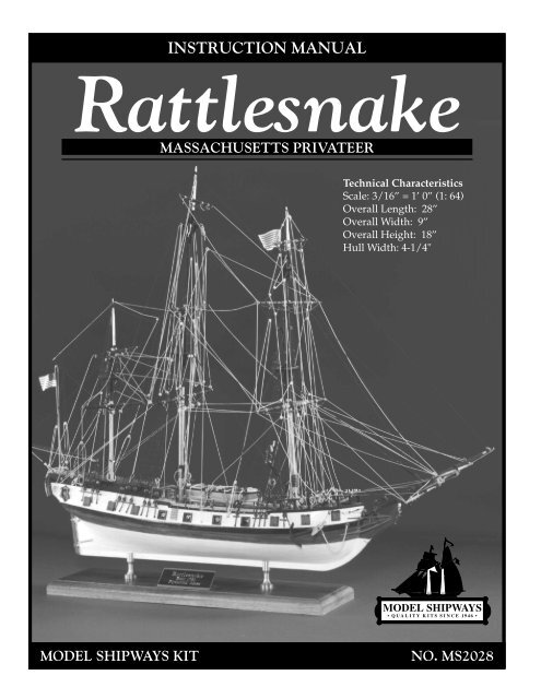
INSTRUCTION MANUAL<br />
<strong>Rattlesnake</strong><br />
MASSACHUSETTS PRIVATEER<br />
Technical Characteristics<br />
Scale: 3/16” = 1’ 0” (1: 64)<br />
Overall Length: 28”<br />
Overall Width: 9”<br />
Overall Height: 18”<br />
Hull Width: 4-1/4"<br />
MODEL SHIPWAYS KIT<br />
NO. MS2028
<strong>Instr</strong>uction <strong>Manual</strong><br />
Massachusetts Privateer<br />
<strong>Rattlesnake</strong><br />
1780<br />
By George F. Campbell, 1963<br />
Plank-On-Bulkhead Construction and <strong>Manual</strong><br />
By Ben Lankford, 1994<br />
Model built by Bob Bruetsch<br />
The Model Shipways Hull and Rigging plans for <strong>Rattlesnake</strong> were prepared in 1963 by<br />
Mr. George F. Campbell, who passed away several years ago. Mr. Campbell was a noted<br />
British marine artist, author, naval architect, and historian. He was a member of the<br />
Royal Institution of Naval Architects. One of his most noteworthy publications is China<br />
Tea Clippers. He also developed the drawings for the Cutty Sark restoration in England<br />
and authored Model Shipways' model handbook, Neophyte Shipmodeler's Jackstay.<br />
The Model Shipways plans prepared by Mr. Campbell are based on Admiralty<br />
draughts and a reconstruction originally published by Howard I. Chapelle in his book,<br />
The History of American Sailing Ships, and also The Search for Speed Under Sail. The rigging<br />
and deck equipment is based on contemporary texts.<br />
The Model Shipways kit of <strong>Rattlesnake</strong> initially offered a solid hull model. This kit has<br />
now been converted to a Plank-On-Bulkhead type hull. The P-O-B hull plans were<br />
prepared in 1994 by Ben Lankford along with this complete new instruction manual.<br />
Copyright 1994<br />
Model Shipways<br />
Sold & Distributed by Model Expo, a Division of Model Shipways, Inc.<br />
Hollywood, FL • www.modelexpo-online.com<br />
2
Brief History<br />
It was supposedly in 1781 that <strong>Rattlesnake</strong> was<br />
built as a privateer at Plymouth, Massachusetts<br />
for a Salem syndicate; John Andrews, and others.<br />
The Preble Papers in the Massachusetts<br />
Historical Society indicate that the designer and<br />
builder was John Peck of Boston. She was first<br />
commissioned on June 12, 1781 with Master<br />
Mark Clark at the helm. This, however, is early<br />
in the year. Consequently, there is some question<br />
about the actual building date. The ship<br />
could have been under construction in 1780 or<br />
earlier.<br />
During 1781, at a time when privateering was<br />
losing its luster, British frigates still lay off the<br />
coasts of noteworthy American colonial towns,<br />
keeping tabs on shipbuilding departures, and<br />
raiding shipping centers. It was along these<br />
routes that <strong>Rattlesnake</strong> met her fate when she was<br />
captured by British 44-gun H.M.S. Assurance.<br />
<strong>Rattlesnake</strong> was sent to England where she was<br />
taken into the Royal Navy and renamed Cormorant.<br />
Her hull lines were taken at the Plymouth<br />
Dockyard in 1782. In 1783, when the<br />
Admiralty found out they already had a ship<br />
named Cormorant, the ship was again named<br />
<strong>Rattlesnake</strong>. In 1784 or 1786, she was sold out of<br />
Naval service. Beyond that her history is not<br />
clear. One source says she was used by the<br />
French as a privateer and named Le Tonnant,<br />
but this is not confirmed by any authority.<br />
Despite her moderate size, <strong>Rattlesnake</strong> was shiprigged<br />
and impressive in appearance and feature<br />
beyond her broadside strength. The ship was 89'<br />
3" long on deck, with a molded beam of 22', a<br />
mean draft of 8' 1-1/2", and 198-70/94th tons<br />
burthen. Her molded displacement was 221.3<br />
long tons. Along with 85 men, she carried twenty<br />
6-pounders only, a psychological ploy no doubt,<br />
but her lines reveal a fast and weatherly ship.<br />
More History<br />
For a fascinating history and technical discussion<br />
of privateering ships, and more detail on<br />
the <strong>Rattlesnake</strong>, refer to The History of American<br />
Sailing Ships and The Search for Speed Under Sail<br />
listed in the bibliography.<br />
3
CONSTRUCTION STAGES & TABLE OF CONTENTS<br />
Brief History Pg 3<br />
Introduction/Credits Pg 2<br />
Before You Begin Pg 5<br />
What You'll Need to Start Construction Pg 5<br />
How to Work With the Plans & Parts Pg 6<br />
Painting & Staining the Model Pg 7<br />
Stage A: Framing the Plank-On-Bulkhead Hull Pg 8<br />
1. Bending Wood Pg 8<br />
2. Center Keel Assembly Pg 8<br />
3. Installing the Keel/Stem & Sternpost Pg 8<br />
4. Cutting the Rabbet Pg 8<br />
5. Installing the Bulkheads Pg 8<br />
6. Installing the Transom Framing & Transom Pg 10<br />
7. Installing the Bow & Stern Filler Blocks Pg 12<br />
8. Covering the Mast Slots Pg 12<br />
9. Installing the Gun Deck Waterway<br />
& Upper Deck Covering Boards Pg 12<br />
10. Installing the Knightheads & Timerheads Pg 12<br />
11. Installing the Main, Forecastle<br />
& Quarter Deck Rails Pg 13<br />
12. Installing the Forecastle<br />
& Quarter Deck Breast Beams Pg 13<br />
13. Installing the Gunport Framing Pg 13<br />
Stage B: Planking the Plank-On-Bulkhead Hull Pg 14<br />
1. Getting Started Pg 14<br />
2. Planking Battens & Belts Pg 14<br />
3. Planking Butts Pg 14<br />
4. Spiling Pg 15<br />
5. Fastening the Planks Pg 15<br />
6. Planking the Outer Hull Pg 15<br />
7. Planking Inboard (Ceiling Planks) Pg 18<br />
8. Planking the Decks Pg 18<br />
Stage C: Completing the Basic Hull Structure Pg 19<br />
1. Correcting & Sanding Pg 19<br />
2. Building the Head Rails Pg 19<br />
3. Gunport Lids Pg 19<br />
4. Building the Gangways Pg 19<br />
5. Natural Wood/Double Plank Option Pg 19<br />
Stage D: Mounting the Hull Pg 20<br />
1. Mounting Board with Two Pedestals Pg 20<br />
2. Launching Ways Pg 21<br />
Stage E: Adding the Hull Details Pg 21<br />
1. Locating Deck Fittings & Structures Pg 21<br />
2. Topsail Sheet Bitts, Fore Brace Bitts,<br />
Riding Bitts & Gallows Bitts Pg 21<br />
3. Ladders Pg 21<br />
4. Hatches & Gratings Pg 21<br />
5. Binnacle Pg 21<br />
6. Capstan Pg 21<br />
7. Catheads & Anchors Pg 21<br />
8. Elm Pumps Pg 24<br />
9. Kevels & Chesstrees Pg 24<br />
10. Galley Chimney Pg 24<br />
11. Channels Pg 24<br />
12. Deck Buckets Pg 24<br />
13. Eyebolts & Cleats Pg 24<br />
14. Rudder & Tiller Pg 24<br />
15. Quarter Badges Pg 25<br />
16. Cannons Pg 25<br />
17. Ship's Name Pg 26<br />
18. Ship's Longboat Pg 26<br />
Stage F: Mast & Spar Construction Pg 27<br />
1. The Importance of Scale Pg 27<br />
2. Shaping & Tapering the Masts & Spars Pg 27<br />
3. Building & Installing the Masts Pg 27<br />
4. Building & Installing the Bowsprit & Jibboom Pg 29<br />
5. Building the Lower, Crossjack, Topsail,<br />
Topgallant & Spritsail Yards Pg 31<br />
6. Building the Spanker Gaff & Boom Pg 31<br />
Stage G: General Rigging & Sailmaking Information Pg 31<br />
Rigging Terms Defined<br />
1. Rigging Options Pg 31<br />
2. Using the Rigging Plan Pg 32<br />
3. Rigging Line & Block Sizes Pg 32<br />
4. Treating the Lines Pg 33<br />
5. Belaying Pins & Their Lines Pg 33<br />
6. Rigging Tools Pg 34<br />
7. Blocks & Deadeyes Pg 34<br />
8. Sailmaking Pg 34<br />
9. Rigging the Model Without Sails Pg 36<br />
Stage H: Standing Rigging Pg 37<br />
1. Shrouds Pg 37<br />
2. Backstays Pg 37<br />
3. Fore & Aft Stays Pg 37<br />
4. Detail at the Tops Pg 37<br />
5. Bowsprit Rigging Pg 37<br />
6. Footropes Pg 37<br />
Stage I: Running Rigging Pg 41<br />
1. Fore Staysail, Fore Topmast Staysail & Jib Pg 41<br />
2. Fore and Main Course,<br />
& Mizzen Crossjack Yard Pg 41<br />
3. Fore, Main & Mizzen Topsails Pg 41<br />
4. Fore & Main Topgallant Sails Pg 43<br />
5. Spanker Pg 43<br />
6. Spritsail & Spritsail Topsail Pg 43<br />
7. Miscellaneous Rigging Pg 43<br />
Final Touches Pg 43<br />
Scale Conversion Table Pg 44<br />
Rigging Line Diameters Pg 44<br />
Millimeters/Inches Conversion Chart Pg 44<br />
Bibliography Pg 45<br />
4
BEFORE YOU BEGIN<br />
WHAT YOU’LL NEED TO START CONSTRUCTION<br />
The <strong>Rattlesnake</strong> is a very beautiful ship<br />
and makes a splendid model. The<br />
plank-on-bulkhead hull construction<br />
with laser-cut parts offers a unique<br />
building experience. It assures an accurate<br />
hull form, and develops an understanding<br />
of how real ships are constructed.<br />
The kit is supplied with a set of Britannia,<br />
brass, and wooden fittings to eliminate<br />
problems in making or machining<br />
such parts from scratch, which<br />
may be beyond the ability or resources<br />
of the average modeler. Many of these<br />
fittings, however, will require final finishing<br />
before they are suitable for installation<br />
on the model. This will be especially<br />
true for the Britannia fittings<br />
and will be discussed later.<br />
This kit will provide less experienced<br />
modelers with the opportunity to acquire<br />
some scratch-building techniques.<br />
As an aid, various techniques<br />
will appear throughout the instructions.<br />
While the modeling progresses,<br />
you will see where you may want to<br />
substitute some of the kit fittings with<br />
your own creations. By all means try<br />
them, especially if you think you can<br />
improve the model. The worst that can<br />
happen is a little lost time. But, the experience<br />
gained will be most valuable<br />
for future projects.<br />
If you are a beginner, take your time.<br />
This model has a fair amount of detail<br />
and small parts. Make sure you complete<br />
one stage before moving to the<br />
next. When things go awry, consider<br />
doing it over.<br />
The following tools and supplies are recommended<br />
for the construction process.<br />
Modelers who have built before may<br />
have their own favorites.<br />
A. Knives<br />
1. <strong>Hobby</strong> knife<br />
2. No.11 blades<br />
B. Files<br />
Set of needle files<br />
C. Clamps<br />
1. A few small C-clamps<br />
2. Wooden clothespins<br />
3. Rubber bands, #16 and #33<br />
D. Tool Set<br />
A small carving tool set or<br />
individual gouges and chisels<br />
for carving center keel rabbets,<br />
the counter block, stern and<br />
bow filler blocks, tapering the<br />
stem, and carving the ship's<br />
longboat.<br />
E. Sharpening Stone<br />
Necessary to keep tools razor sharp<br />
F. Boring Tools<br />
1. Set of miniature drills: #60 to #80<br />
2. 1/16", 3/32", and 1/8" drills<br />
3. Pin vise<br />
G. Miscellaneous<br />
1. Tack hammer<br />
2. Tweezers (a few)<br />
3. Small fine pointed scissors<br />
4. Miniature pliers<br />
a. small round<br />
b. flat nose<br />
5. Bench vise (small)<br />
6. Soldering iron or torch<br />
a. solder<br />
b. flux<br />
7. Sewing thread (for seizing;<br />
other rigging in kit)<br />
a. black<br />
b. tan<br />
8. Beeswax block (for treating<br />
rigging lines)<br />
9. 1/2" or 3/4" masking tape<br />
10. Wire cutters (for cutting fine<br />
wire and strip metal)<br />
H. Sandpaper<br />
Fine and medium grit garnet or<br />
aluminum oxide sandpaper<br />
(#100 to #220)<br />
I. Sail cloth<br />
Light weave cotton or linen cloth if<br />
you intend to add sails. A suitable<br />
cotton cloth is available from Model<br />
Expo.<br />
J. Finishing<br />
1. Paint Brushes<br />
a. fine point for details<br />
b. 1/4" to 1/2" flat square<br />
for hull<br />
K. Supplies<br />
(will be covered in detail in the<br />
Painting & Staining section and<br />
throughout the instructions)<br />
1. Paints<br />
2. Primer<br />
3. Stains and varnish<br />
4. White or Carpenter's (yellow)<br />
wood glue<br />
5. Super glue<br />
6. Five-minute epoxy glue<br />
7. Wood filler<br />
Note about glues: White glue, or Carpenter's<br />
wood glue (yellow in color; also<br />
available in tan color), will suffice for<br />
most of the model. Five-minute epoxy<br />
provides extra strength for gluing fittings.<br />
Cyanoacrylate glue (super glue),<br />
such as Jet, can be used for quick adhesion<br />
and is ideal for adding a touch to a<br />
rigging seizing to hold it in place. The<br />
best super glue for most applications is<br />
a medium viscosity gap filling type. The<br />
watery thin type is recommended to fill<br />
a narrow crack by capillary action, and<br />
for quickly securing hull planking to the<br />
bulkheads.<br />
5
HOW TO WORK WITH THE PLANS & PARTS<br />
Before starting model construction, examine<br />
the kit and study the plans carefully.<br />
Familiarizing yourself with the kit<br />
will serve two purposes. First, it will let<br />
you determine that all parts have been<br />
supplied as listed. And second, you'll be<br />
surprised at just how quickly handling<br />
the parts allows you to better understand<br />
the kit requirements. Try to visualize<br />
how every part will look on the<br />
completed model. Also, determine<br />
ahead of time what must be done first.<br />
The instructions will help you in this regard,<br />
but a thorough knowledge of the<br />
plans at the outset is essential.<br />
It is suggested that all small fittings and<br />
hardware be sorted into labeled boxes or<br />
compartments to avoid loss during the<br />
building process.<br />
1. The Plans<br />
Four Plan Sheets are provided:<br />
1963 Plans by George Campbell:<br />
1. Hull Details and Lines Plan<br />
2. Rigging Plan<br />
1994 Plans by Ben Lankford:<br />
3. Laser-Cut Wood Patterns<br />
4. Plank-On-Bulkhead Hull Construction<br />
In addition, a set of sketches appears<br />
throughout this instruction manual to<br />
further illustrate the various stages of<br />
construction.<br />
The <strong>Rattlesnake</strong> kit is manufactured to a<br />
scale of 3/16" = 1' 0". Each plan sheet is<br />
drawn to the exact scale that the model<br />
is to be built, except where some details<br />
have been enlarged for clarity. Most dimensions<br />
can be lifted directly off the<br />
plans by using a set of draftsman dividers<br />
or by using a "tick" strip, which is<br />
simply a piece of paper used to "pick<br />
up" the dimensions (a roll of calculator<br />
tape works very well). Lay your paper<br />
strip over the plan and mark the lengths<br />
of items carefully with a sharp pencil.<br />
Then use the strip to transfer the marks<br />
to the wood or item to be made to scale.<br />
It is handy to have a triangular architect's<br />
scale. Measuring and cutting parts using<br />
the 3/16" scale gives you a better feel for<br />
real ship sizes. It also gives you a conversion<br />
for the full ship size dimensions<br />
shown on the plans. At 3/16" scale, one<br />
inch in full ship size equals 1/64". Keep<br />
this in mind as you work. You will soon<br />
know, for example, that if you see something<br />
4 inches wide full scale, your<br />
model part will be 1/16".<br />
2. Making Allowances Along the Way<br />
Try to be exact when following the plans,<br />
but use common sense along the way.<br />
You may need to make adjustments or<br />
allow for small differences in how your<br />
model is shaping up; perhaps your mast<br />
has too much rake (the angle at which it<br />
sits). When lines go to belaying points<br />
they should not drape over parts or conflict<br />
with other lines. If necessary, move a<br />
belaying point or a fairlead. In other<br />
words, put yourself on the ship and use<br />
your judgement.<br />
3. Understanding Hull Lines<br />
Beginners may not be familiar with hull<br />
lines. Buttock lines are vertical longitudinal<br />
planes cut through the hull. Waterlines<br />
are horizontal planes, and sections<br />
are transverse vertical planes. All<br />
of these lines define the hull shape and<br />
are used by the draftsman to fair the<br />
hull form (create regular even curves).<br />
A complete set of hull lines is shown on<br />
the George Campbell plans but they are<br />
not really needed for this particular<br />
model. With the plank-on-bulkhead<br />
construction, the laser-cut bulkheads<br />
and center keel define the hull form.<br />
These are based on the <strong>Rattlesnake</strong> hull<br />
lines to outside of the planking, but are<br />
made smaller to allow for the thickness<br />
created by adding the planks.<br />
4. Using Basswood Lumber<br />
Standard cut basswood is available in<br />
sheets and strips. Normally, thickness is<br />
available in 1/32", 1/16", 3/32", 1/8",<br />
5/32", 3/16", 1/4", and 1/2". Widths of<br />
strips are available in the same increments.<br />
Sheets may be 1", 2", 3", or 4". A<br />
thickness of 3/64" is also a manufactured<br />
thickness, but not found in many<br />
catalogs. However, if needed, it will be<br />
provided in Model Shipways kits.<br />
Note: Your kit may contain European<br />
limewood instead of the basswood most<br />
of us are familiar with. For further information<br />
see the notes in the parts list.<br />
For the model scale 3/16" = 1' 0", 1/64"<br />
is equal to 1" full ship size. 1/32" is<br />
equal to 2", and so on. Generally, the<br />
available sizes of basswood fit the full<br />
ship size quite well and the strips or<br />
sheets can be used directly. Occasionally,<br />
you will find a size where the strip<br />
must be thinner than the basswood size<br />
supplied. In order to use a correct thickness,<br />
you will need to sand down a certain<br />
thickness of basswood. This is easily<br />
done with a sanding block before<br />
making a part.<br />
If you are fortunate enough to own a<br />
powered sanding thickness planer for<br />
models, all the better. These can be purchased<br />
commercially. You can also make<br />
your own using a drum sander in a drill<br />
press. Clamp a block alongside the sander<br />
so the wood can be inserted between the<br />
block and sander. It's a makeshift deal,<br />
but it works quite well.<br />
It is a good idea to sort the wood contained<br />
in the kit by thickness. When<br />
building a certain part, select a suitable<br />
size from the proper thickness pile. After<br />
cutting what you need, return the remaining<br />
piece to that thickness pile. This saves<br />
a lot of time looking for a given thickness.<br />
Don't worry about using a piece for one<br />
item that was intended for another. It will<br />
all come out in the wash. There is enough<br />
extra wood in the kit so you should not<br />
run out before you complete the model.<br />
5. Cast-Metal Fittings<br />
The kit is supplied with Britannia metal<br />
castings. The Britannia metal is a great<br />
improvement over the white metal that<br />
was used in some older kits. Unlike<br />
white metal and pewter, Britannia does<br />
not contain lead, so there are no possible<br />
corrosion problems. Many of these fittings,<br />
however, will require final finishing<br />
before they are suitable for installing<br />
on the model.<br />
Before painting the cast-metal fittings,<br />
clean them up by removing all the moldjoint<br />
flash. To do this, use a No. 11<br />
hobby blade to cut the flash, then file or<br />
sand with fine sandpaper. It is also suggested<br />
that you clean the fittings thoroughly<br />
with warm soapy water before<br />
applying primer. Make sure they are<br />
rinsed thoroughly and allowed to dry<br />
before painting.<br />
6. Soldering & Working with Brass<br />
The <strong>Rattlesnake</strong> is a ship from a period<br />
that had very little iron fittings. Consequently,<br />
you will not be required to do<br />
much soldering, if any. Gudgeons, pintles,<br />
and chain plates could be soldered<br />
or simply glued. If you do solder, the secret<br />
is to keep the parts to be soldered<br />
clean, and keep the end of your soldering<br />
iron clean and well tinned. File or sand<br />
the parts, then keep your fingers off. Heat<br />
the parts first, then touch the solder. File<br />
off any excess solder.<br />
6
PAINTING & STAINING THE MODEL<br />
It may seem strange to begin an instruction<br />
manual with directions on applying<br />
the finishes to the model. Not so! Much<br />
time and effort can be saved, and a more<br />
professional result can be obtained, if<br />
the finishing process is carried out during<br />
construction. Proper timing in application<br />
of finishes and the use of masking<br />
tape to define painted edges should<br />
eliminate unsightly glue marks and<br />
splotchy stained surfaces. In the end,<br />
following these general suggestions will<br />
be to your advantage.<br />
Paint<br />
Use a flat-finish paint such as the model<br />
paints made by Floquil, Polly-S, Testors,<br />
Humbrol, and Model Masters. You<br />
could also use artist's paints by Jo Sonja<br />
(used by many bird carvers) or Holbein<br />
Acryla Gouache. These paints are a<br />
combination acrylic-gouache.<br />
Paint Colors<br />
The recommended color scheme for the<br />
<strong>Rattlesnake</strong> is as follows:<br />
Topside Rails: Yellow Ochre<br />
Quarter Deck Outboard Bulwark<br />
Planking between Rails: Black<br />
Outboard Planking from Rails down to<br />
the top of Wales: Yellow Ochre<br />
A Parallel Band about 1/2" wide from<br />
top of the Wales, and including the<br />
Upper part of the Stem: Black<br />
Head Rails: Yellow Ochre<br />
Hull Bottom below the Black Band:<br />
White or Tallow (or lighter tallow plus<br />
white). Note: Tallow is an ivory color<br />
and is available pre-mixed in Floquil<br />
model paint available from Model Expo.<br />
Stern Window Frames: White<br />
Center Dummy Window Panes: Pale<br />
Blue<br />
Figurehead: Any bright colors<br />
Bulwarks Inboard: Grey<br />
Decking: Natural light Tan or Grey<br />
stain with low sheen varnish<br />
Masts, Spars and Deck Bitts: Burnt Sienna<br />
stain, or any Tan/Maple colored<br />
stain with low sheen varnish<br />
Tops & Doublings (top up and including<br />
mast caps), and Bands around Fore<br />
and Main Mast: Black<br />
Longboat: Tallow or White bottom, Natural<br />
varnished sides and interior (Tan or<br />
Maple stain), Black outboard molding<br />
and Red spray rail<br />
Ironwork: Black<br />
Standing Rigging: Tarred (Black or<br />
Dark Brown)<br />
Running Rigging: Tan or Weathered<br />
Grey<br />
Primer<br />
Use a Grey primer. Floquil is excellent.<br />
The Grey color will highlight sanding<br />
scratches and other defects better than<br />
White primer. Prime all woodwork to be<br />
painted, and prime all metal fittings.<br />
Lightly sand the primed items. Use a<br />
spackling compound, such as Pic-n-<br />
Patch brand, to fill any scratches and defects,<br />
then re-prime. Careful! Do not<br />
prime parts to be stained or varnished.<br />
Stains & Finishes<br />
For natural finished wood, use a protective<br />
coating after staining such as low<br />
sheen polyurethane varnish or the Floquil<br />
coatings. You can also use an oilresin<br />
mix such as natural Minwax. Floquil<br />
stain, or Minwax stains can be used<br />
to tone the wood.<br />
Brushes & Procedures<br />
Use good quality soft sable or synthetic<br />
hair artist brushes. A small pointed<br />
brush is good for details. For the main<br />
hull areas, use a 1/4- to 1/2-inch flat<br />
brush.<br />
Before painting, clean the model with a<br />
tack rag. Apply your paint in smooth<br />
even strokes, overlapping the strokes as<br />
you go. Thin the paint enough to eliminate<br />
brush strokes, but not run. You will<br />
need four or five coats of the light colors<br />
to cover the Grey primer, and maybe<br />
only two coats of the dark. Check your<br />
finish between coats, and sand or add<br />
spackle as necessary to get rid of any<br />
blemishes.<br />
Anywhere two colors meet, use masking<br />
tape. Electrician's black plastic tape is<br />
ideal. It leaves a nice edge and is not<br />
overly sticky. Do not use drafting tape.<br />
The edges are wrinkled and paint may<br />
run under them.<br />
7
STAGE A<br />
FRAMING THE<br />
PLANK-ON-BULKHEAD HULL<br />
FIG. 1 - Assembling The Two Center Keel Pieces<br />
8<br />
1. Bending Wood<br />
Building a P-O-B hull requires some<br />
wood bending and twisting, and the<br />
wood must remain in the desired position<br />
so as not to put too much stress on<br />
glue joints and fasteners. The term<br />
"steam-bent" will be used throughout<br />
the text whenever such a process is necessary.<br />
However, here are three ways to<br />
bend wood.<br />
Steam-bending - For actual steam-bending,<br />
hold the piece over a kettle of<br />
steaming water and bend. Hold the<br />
wood in position until it cools. It should<br />
remain nearly in that position, but may<br />
spring back slightly.<br />
Soaking - Another method is to soak the<br />
piece in warm water for several hours.<br />
Try adding a little household ammonia<br />
to the water. You can also use pure ammonia.<br />
This speeds up the soaking process<br />
and makes the wood fibers slippery<br />
so the wood is easily bent. Hold the<br />
wood in position with a form after soaking<br />
and let it dry completely.<br />
Hot iron - You may also bend wood<br />
quickly over a soldering iron, but don't<br />
let it get too hot. A large soldering iron<br />
with a tubular end is ideal. The tube near<br />
the handle is not as hot as the very end.<br />
It is also possible to purchase model<br />
plank-bending irons commercially. They<br />
are designed for controlled heat.<br />
2. Center Keel Assembly<br />
The first step in constructing the hull is<br />
to assemble the two laser-cut center keel<br />
pieces. First, use a sharp pencil and<br />
mark the bulkhead locations below the<br />
slots and the WL reference line. This<br />
line is used to locate Bulkheads "A"<br />
through "M" on the center keel. Mark on<br />
both sides of each center keel piece. Be<br />
especially critical in locating the reference<br />
line. Measure from several points<br />
from the plans. The reference line is a<br />
key to proper alignment.<br />
Place the two parts, 1 and 2, over a sheet<br />
of wax paper or plastic wrap, on a flat<br />
building board or table. Glue the joint<br />
with white or carpenter's wood glue.<br />
Use a steel or aluminum straight edge<br />
to align the WL reference line. Place a<br />
weight on each piece to hold it down<br />
while the glue dries. Let the glue dry at<br />
least overnight, preferably 24 hours (see<br />
figure 1).<br />
Wax paper or<br />
plastic wrap<br />
Building board<br />
or table<br />
3. Installing the Keel, Stem<br />
& Sternpost<br />
For this particular model, the center keel<br />
is only 5/32" thick. With 1/16" hull<br />
planking, after cutting a rabbet on both<br />
sides, there is not much left of the center<br />
keel for attaching the keel, stem and<br />
sternpost. Consequently, it is recommended<br />
that you first install the keel,<br />
then cut the rabbet as you add planking.<br />
The keel will remain secure along most<br />
of the hull by this approach.<br />
The keel, stem, and sternpost should<br />
now be added. Taper the stem as shown<br />
on the plans before installing it. Dowels<br />
can be used to help align and hold the<br />
pieces (see figure 2).<br />
4. Cutting the Rabbet<br />
With the keel now in place, the rabbet is<br />
the glue line between the center keel and<br />
the keel. The bearding line is the intersection<br />
of the center keel and the inside<br />
face of hull planks. Mark the bearding<br />
line on both sides. The bearding line appears<br />
along the sternpost, keel, and<br />
stem. Measure from the P-O-B plans.<br />
Use a hobby knife and cut the rabbet to a<br />
depth of about 1/32". Cut on or slightly<br />
above the glue joint. Now, using a chisel,<br />
start the rabbet cut at the bearding line<br />
and cut toward the rabbet . When the<br />
planking is installed, the planks will lie<br />
Weight<br />
Glue joint<br />
Straight edge to align<br />
reference line<br />
flush on the cut portion from bearding<br />
line to rabbet (see figure 3). As you cut<br />
the rabbet, continue to use the hobby<br />
knife to gradually work your way down<br />
to the full 1/16" depth for the rabbet to<br />
fit the planks.<br />
5. Installing the Bulkheads<br />
The bulkheads are labeled A through M.<br />
Compare the laser-cut bulkheads with<br />
the plans to determine which is which<br />
and label each bulkhead. Check each<br />
bulkhead to make sure it will slide into<br />
the center keel slots. Machine tolerances<br />
during laser cutting may provide a too<br />
tight fit. Sand the slots, if necessary,<br />
until the bulkheads slip on. The fit<br />
should be snug. You need a little tolerance<br />
for glue.<br />
The bulkheads include cutouts at the gun<br />
deck. Also, the bulkheads include extensions<br />
for rail stanchions. These areas are<br />
only 1/16" thick, so be careful handling<br />
them to avoid breakage. After the stanchions<br />
have been planked, with hull<br />
planks on the outboard side and ceiling<br />
planks on the inboard side, the shell will<br />
have obtained maximum strength.<br />
On each bulkhead, mark the location of<br />
the WL reference line in pencil. This<br />
mark should line up with the WL mark<br />
on the center keel. This alignment assures<br />
that the hull form is accurate and<br />
that each bulkhead is correctly related to<br />
the others.
FIG. 2 - Installing The Keel, Stem & Stern<br />
2<br />
Taper<br />
4<br />
Add dowels as necessary<br />
Add<br />
sternpost<br />
3<br />
Add keel/stem<br />
1<br />
Glue scarf joints<br />
Next, mark the bevels on the bulkheads.<br />
Use a tick strip to transfer the bevel line<br />
as shown on the plans, or cut the bulkhead<br />
patterns from the plan and glue<br />
them onto the bulkheads. You can also<br />
lay the patterns over the bulkheads and<br />
use a pin prick to locate the bevels. Cut<br />
the bevels with a #11 hobby knife blade<br />
as shown (see figure 4).<br />
Some of the bevels are very slight, especially<br />
the deck bevels and the side<br />
bevels near amidships. These slight<br />
bevels are not drawn because they are<br />
hardly measurable. They can be sanded<br />
after the bulkheads are installed instead<br />
of pre-cutting them.<br />
Glue the bulkheads in place, making<br />
sure that the WL marks on the bulkheads<br />
and the center keel line up. Use a<br />
square to make each bulkhead perpendicular<br />
to the center keel, then tack a<br />
temporary strip to the top to hold the<br />
bulkhead in place while the glue dries<br />
(see figure 5).<br />
After all bulkheads are in place, tack or<br />
tape a temporary batten on each side of<br />
the hull just below the gun deck as shown<br />
(see figure 6). This is a critical step. Measure<br />
the spacing between bulkheads and<br />
retack the battens until the hull is aligned.<br />
Even though the center keel was assembled<br />
flat, it could warp out of line. The result<br />
could be that you wind up with a banana-shaped<br />
hull. Check the spacings between<br />
bulkheads, and port against starboard<br />
spacings. Look at the hull to see if it<br />
is properly aligned.<br />
When you are satisfied that the hull is<br />
aligned, check that the bottom of each<br />
bulkhead feathers out and lies precisely<br />
on the bearding line. Trim as necessary<br />
to line up. Also, check that the top of<br />
each bulkhead at the centerline is flush<br />
with the top of the center keel. Since all<br />
alignment is based on the WL marks,<br />
there could be some slight errors. Sand<br />
or add shims as necessary until the<br />
bulkheads and center keel surfaces are<br />
flush (see figure 7).<br />
FIG. 3 - Cutting The Rabbet in The Center Keel<br />
FIG. 4 - Shaping The Bulkheads<br />
Deck bevel<br />
Bevel marked<br />
with pencil<br />
<strong>Hobby</strong> knife<br />
Slot with knife<br />
Cut with<br />
wood grain<br />
Bevel<br />
inside<br />
also<br />
<strong>Hobby</strong><br />
knife<br />
Chisel<br />
Rabbet<br />
Bearding line<br />
FIG. 5 - Installing The Bulkheads<br />
Ref. lines<br />
must line<br />
up<br />
BHD<br />
Tack or<br />
tape strip<br />
until<br />
glue<br />
dries<br />
Check 90°<br />
with square<br />
9
Next, check the fairness of the hull form<br />
and sand in the slight bevels that were<br />
not pre-cut. To do this, use a stiff basswood<br />
batten about 3/32" thick and lay it<br />
across the bulkhead edges and decks in<br />
various locations (see figure 8). If not<br />
fair, sand the bevels that stick out, or<br />
add shim material if there are dips. This<br />
is an important check. When you start<br />
planking, the planks must lie flat against<br />
the bulkheads without incurring any<br />
bumps and dips on the surface. A model<br />
like <strong>Rattlesnake</strong> has many bulkheads, so<br />
it is possible for manufacturing or assembly<br />
errors to creep in.<br />
FIG. 6 - Aligning The Bulkheads, Using Battens<br />
Check alignment<br />
visually in all directions<br />
Check spacing<br />
Check straightness of<br />
center keel with<br />
straight edge<br />
6. Installing the Transom<br />
Framing & Transom<br />
Carve the counter block, and glue it to<br />
the aft side of Bulkhead M and on top of<br />
the center keel. Glue the port and starboard<br />
laser-cut outboard transom support<br />
pieces and two inboard transom<br />
supports on top of the counter block.<br />
The forward end of the outboard pieces<br />
fit against the Bulkhead M bulwark<br />
stanchion extensions.<br />
Follow the plans when carving the<br />
counter block. The bottom of the block<br />
has the counter curve. The forward side<br />
matches Bulkhead M . The aft side of<br />
the block indicates the slope and curvature<br />
of the transom. At the center, there<br />
is a cut-out so the rudder stock can pass<br />
through (see figure 9).<br />
The transom is a laser-cut piece. While it<br />
was made up of planks over stern frames<br />
on the real ship, for the model a solid<br />
piece has been provided so no planking<br />
is required. Glue the transom to the side<br />
and center supports (see figure 10).<br />
There are two openings on each side of<br />
the transom for windows, and at the<br />
center for a fake window. The window<br />
frames are laser-cut and can be inserted<br />
in the holes. First cover the inside with<br />
plastic sheet and paint light blue or<br />
black. The center window was a dummy<br />
window on the real ship. Paint the panes<br />
pale blue. Add the outside frames with<br />
1/32" strip, sanded half-round. Add the<br />
lower moldings as shown in the sketch.<br />
The stern carving is supplied as a Britannia<br />
fitting, but you can carve your own<br />
from wood if desired. If you use the fitting,<br />
it will need shaping a bit to fit the<br />
transom. Cut sloped edges as required.<br />
After the planking is done you must add<br />
the fashion piece at the transom. This is<br />
discussed now to avoid any confusion<br />
(see figure 11). Finally, drill some holes<br />
in the top edge of the transom to receive<br />
the rail stanchions.<br />
FIG. 7 - Making Sure Bulkhead & Center Keel Surfaces Are Flush<br />
Sand flush with<br />
top of bulkheads<br />
if necessary<br />
FIG. 8 - Check The Fairness Of The Hull Form<br />
Needs shim<br />
(gap)<br />
Needs trimming<br />
(bump)<br />
Smooth<br />
flow into<br />
rabbet<br />
Good<br />
Tack temporary batten<br />
on bulkheads<br />
Line up with reference line<br />
on center keel<br />
Bearding line<br />
Trim if necessary to line<br />
up on the bearding line<br />
Good<br />
Heavy batten across several bulkheads to check fairness<br />
10
FIG. 9 - Carving The Counter Block At Bulkhead “M”<br />
Side transom<br />
support–P/S<br />
Inboard transom<br />
support–P/S<br />
Carved counter block<br />
BHD “M”<br />
BHD = Bulkhead<br />
P/S = port/starboard<br />
FIG. 10 - Installing The Transom<br />
FIG. 11 - Installing The Two<br />
Fashion Pieces<br />
Side support<br />
Inboard support<br />
Glue<br />
Glue<br />
Glue<br />
Fashion piece<br />
Fashion piece curves in 2 directions,<br />
so it must be custom carved<br />
Laser-cut transom<br />
Bend to curve of<br />
counter block<br />
(Side view)<br />
(Front view)<br />
11
7. Installing the Bow & Stern<br />
Filler Blocks<br />
Forward of Bulkhead A and aft of Bulkhead<br />
M, add the filler blocks as shown<br />
on the plans. Carve the blocks to the hull<br />
form. The purpose of these blocks is to<br />
have more support where the planks<br />
take a severe curve. You will still need to<br />
steam bend planks at the ends, but with<br />
the blocks in place, the planks are not as<br />
likely to break as they pass over the last<br />
bulkheads. In addition, the forward<br />
block gives a solid piece for inserting the<br />
timberheads and knightheads forward<br />
(see figure 12).<br />
8. Covering the Mast Slots<br />
On both sides of the mast slots in the<br />
center keel, add the pieces shown on the<br />
P-O-B plan. Cut from scrap wood. Glue<br />
them securely, because you can't get to<br />
them after the decking is installed. The<br />
mast slots are slightly larger than the actual<br />
mast. The mast can be wedged in<br />
the hole when installed.<br />
FIG. 12 - Installing The Bow Filler Block<br />
BHD “A”<br />
Slots for knighthead<br />
& timberhead<br />
Carved filler block<br />
FILLER BLOCK AT BOW<br />
9. Installing the Gun Deck<br />
Waterway & Upper Deck<br />
Covering Boards<br />
At the gun deck level, add the waterway<br />
along the deck edge inboard of the bulkhead<br />
extensions (see figure 13). You can<br />
omit the waterway in the officer's quarters<br />
since it cannot be seen.<br />
At the forecastle deck, the covering<br />
boards at the edge of the deck as shown<br />
in the sketch are laser-cut. Add these<br />
next. Aft, add the covering boards as<br />
shown on the plans and the sketch.<br />
These must be made from stripwood.<br />
Actually, this is a fake covering board.<br />
You will have a separate piece inboard<br />
and a separate piece outboard instead of<br />
a solid piece fitted over frames. For the<br />
outboard piece, plank the hull first, then<br />
add the strip, or use the option shown<br />
on the plans for a single piece.<br />
10. Installing the Knightheads<br />
& Timberheads<br />
Make the knightheads and timberheads<br />
and install them in a notch in the forward<br />
filler block (see figure 12).<br />
FIG. 13 - Gun Deck Waterway & Upper Deck Covering Boards<br />
Gun deck<br />
Laser-cut<br />
board<br />
Waterway from<br />
1/8” sq. strip<br />
Outboard strip over<br />
plank or use one single<br />
piece as an option<br />
Focsl<br />
Gun<br />
Inboard covering<br />
board from<br />
stripwood<br />
Option:<br />
Omit AFT<br />
(AFT)<br />
QTR<br />
Gun<br />
(FWD)<br />
12
11. Installing the Main, Forecastle<br />
& Quarter Deck Rails<br />
Because the forecastle deck has more<br />
curvature, it has been laser cut for you.<br />
Cut all the other rails from strip wood.<br />
At the forecastle deck, first make and insert<br />
the rail stanchions in the pre-cut<br />
holes in the covering board. When<br />
adding rails, use a pin or dowel for alignment<br />
and for securing the rail atop the<br />
stanchions and bulwarks (see figure 14).<br />
At the various steps, you will need to<br />
create scroll work from one rail to the<br />
other. Carve these scrolls as shown (see<br />
figure 15).<br />
12. Installing the Forecastle &<br />
Quarter Deck Breast Beams<br />
The breast beams forward and aft must<br />
be added before you do the deck planking.<br />
The aft beam ties into a bulkhead but<br />
the forward beam has nothing yet at the<br />
sides to tie into. Add a strut between<br />
bulkheads for end support (see figure 16).<br />
FIG. 14 - Installing The Main, Forecastle & Quarter Deck Rails<br />
Dowel or pin<br />
Laser-cut rail<br />
Stanchions<br />
Laser-cut forecastle<br />
covering board<br />
13. Installing the Gunport Framing<br />
Use 1/16"–square strips to frame the<br />
gunports and the small oar ports in the<br />
hull. The strips fit between the bulkheads<br />
(see figure 17).<br />
Most of the basic framing is now complete<br />
and you are ready to start planking.<br />
Take a moment to look over what<br />
you have so far. Recheck the fairness of<br />
the hull. Making corrections now will<br />
allow the planking process to go<br />
smoothly.<br />
FIG. 15 - Carving The Scrolls For The Rails<br />
Upper rail<br />
Carve scroll<br />
Lower rail<br />
Glue<br />
FIG. 16 - Installing The Forecastle<br />
& Quarter Deck Breast<br />
Beams<br />
Beam<br />
BHD “C”<br />
FIG. 17 - Installing The Gunport<br />
Framing<br />
Gun port<br />
Oar port<br />
End<br />
support<br />
strut<br />
1/16” sq.<br />
framing<br />
strips<br />
BHD “D”<br />
Breast beam forward<br />
13
STAGE B<br />
Planking the<br />
Plank-On-Bulkhead Hull<br />
Before getting started, it 's a good idea<br />
to know some of the more common<br />
shipbuilding terms that apply to the<br />
planking process. Consider the following<br />
few key words as you work:<br />
1. A plank is a single length of wood<br />
used for planking a hull or deck. A<br />
planking strake is a continuous line of<br />
planks, butted against each other from<br />
bow to stern, or wherever the strake begins<br />
or ends.<br />
2. A garboard strake is that strake of<br />
planking adjacent to the keel.<br />
3. The sheer strake is the uppermost<br />
main hull strake.<br />
4. The wale is a heavy layer of strakes<br />
below the sheer strake along the hull's<br />
side. For the <strong>Rattlesnake</strong> the upper edge<br />
of the wale protrudes beyond the planking<br />
above. However, there is no lower<br />
wale edge. The heavier wale planks<br />
gradually taper into the lower planking<br />
so the hull surface is flush from the top<br />
edge of the wale down to the keel rabbet.<br />
5. When discussing planking belts, we<br />
are talking about a group of planks<br />
along the hull. Belts are laid out using<br />
battens, which are temporary strips of<br />
flexible wood used to locate the belt. A<br />
ribband is also a batten, used on boats<br />
and ships to hold the frames in place<br />
while the planking is being added. Ribbands<br />
are removed as the planking is<br />
completed.<br />
6. Spiling is a term used to describe a<br />
process for marking and cutting a plank<br />
to a given shape.<br />
7. Edge bending, also called springing, is<br />
when you bend a plank edgewise.<br />
8. When planking, the use of the word<br />
fair refers to smooth, gradual curves.<br />
9. Nib or nibbing is where one plank runs<br />
into another at a sharp angle. In order to<br />
eliminate the feathered edge, the plank<br />
is cut off on the end and it is fitted into a<br />
similar cut in the other plank. Nibbing is<br />
generally applied to decks, but hull<br />
planks also can be nibbed.<br />
10. A stealer is a plank inserted into another<br />
plank , or notched in between two<br />
adjacent planks when the planks become<br />
too wide. Or, when two planks are<br />
tapering toward a narrow end, it may be<br />
necessary to cut off both planks, then<br />
substitute a wider plank to continue so<br />
there will be enough wood left for fastening<br />
the end of the plank. I'm at a loss<br />
FIG. 18 - Planking With Stealers<br />
for the proper term for this. One model<br />
publication calls it a joggle plank, but I'm<br />
not sure about that. Stealer is a common<br />
term, but joggle plank is not.<br />
11. The counter is the underside of the<br />
overhanging portion of a ship's stern.<br />
1. Getting Started<br />
The planking process is tedious and you<br />
should plan on spending some time<br />
doing the job. Work on each plank as a<br />
project unto itself. Rushing will only result<br />
in frustration and a poor result.<br />
Since both sides of the hull will be identical,<br />
you can cut two planks the same<br />
shape at once. Fit the plank on one side,<br />
then the other. Before starting, place the<br />
hull upside down and secure it in a vise<br />
or cradle. Something portable would be<br />
ideal so you can rotate the hull easily.<br />
2. Planking Battens & Belts<br />
Stealer<br />
It is easier to plank a hull by first dividing<br />
the hull into a series of belts. The<br />
belts flow along the hull in smooth<br />
curves. Each belt is designed so the<br />
planks lay against the hull without excessive<br />
edge bending of the planks. They<br />
sweep up at the ends like the deck sheer.<br />
Within each belt, the planks are usually<br />
spaced evenly, tapered, and fitted as required.<br />
The belts help accomplish the<br />
Planks getting too wide<br />
Planks getting too narrow<br />
complete job without accumulating errors<br />
as you work.<br />
When selecting a belt width and the<br />
number of planks within each belt, you<br />
need to consider how the planks will lay<br />
against the frames and how they will<br />
taper. If the planks are too wide, they<br />
will not lay flat on the bulkheads. Also,<br />
you don't want them to taper so much<br />
that there is no width left for fasteners.<br />
This would require substituting a larger<br />
plank for two to increase width. Also, in<br />
some areas, the planks may get wider<br />
rather than taper. If they get too wide, a<br />
stealer plank must be cut into the plank.<br />
While these alterations are acceptable<br />
and are used on many ships, it is best to<br />
design the run of planking to limit the<br />
number of such inserts (see figure 18<br />
which illustrates some of these inserts).<br />
For the <strong>Rattlesnake</strong> model, a planking layout<br />
has already been developed for you.<br />
The layout is show on the P-O-B plan.<br />
3. Planking Butts<br />
Single plank<br />
insert<br />
Before you start, consider the planking<br />
butts. Since the lengths of wood cut<br />
from trees are generally shorter than the<br />
overall lengths of real ships, shipbuilders<br />
generally have to work with<br />
planks 20 or 30 feet long. Some modelers<br />
think it is easier to use a plank length the<br />
full length of the model. Fake butts can<br />
be scribed in later or omitted. Granted,<br />
this can be done. It's really up to the<br />
14
FIG. 19 - Staggering The Planking Butts<br />
Bulkheads<br />
Real ship–must have 3 strakes between<br />
butts on same frame (model meets rule<br />
with plank length selected)<br />
Real ship–must be 5’ or more<br />
(model meets rule)<br />
modeler. However, by using shorter<br />
pieces there are some advantages. Since<br />
all planks taper to some degree, using<br />
the shorter piece will let you mark the<br />
taper quick, and the plank will be easier<br />
to fasten in place. And with a short<br />
piece, only one hand is necessary to hold<br />
it down. Also, if you make a mistake,<br />
you only have a small piece to do over.<br />
So, the following is based on the use of<br />
the shorter lengths.<br />
Planking butts will not be exactly like a<br />
real ship. Because the model is built on<br />
the bulkhead system, planking butts<br />
must occur on bulkheads.<br />
Use a plank length to cover four bulkhead<br />
spaces. This is a comfortable length<br />
to handle for this model; about 5" to 6".<br />
To scale, that's a plank 27 to 32 feet long.<br />
However, to avoid having very short<br />
pieces at the bow and stern, you may<br />
need to use a longer or shorter plank to<br />
complete the run.<br />
To follow real ship rules, you should<br />
stagger the butts on the model (see figure<br />
19 for a sequence that is similar to a<br />
real ship). The stagger also applies to the<br />
deck planking. The plank covering four<br />
bulkhead spaces works well with the<br />
rules. With this length you can meet the<br />
rule for three full plank widths between<br />
butts on a single frame. If you use a<br />
plank length to cover only three bulkhead<br />
spacings, this would not be possible.<br />
Since the butts occur on bulkheads,<br />
you would wind up with only two full<br />
planks between the butts.<br />
4. Spiling<br />
Edge bending planks on a real ship is<br />
done, but it is limited. The wood is very<br />
stiff, so many planks must be cut to<br />
shape. Spiling is the term used for laying<br />
out the cuts (see figure 20). It's simply a<br />
matter of transferring curves to a straight<br />
plank, then sawing the plank to shape.<br />
For the <strong>Rattlesnake</strong> model, any stealers required<br />
are shown on the planking layout.<br />
For most narrow planks, the basswood<br />
strips are flexible enough so they<br />
can be edge bent in place.<br />
5. Fastening the Planks<br />
There are some fancy plank clamps on the<br />
market, but they are more trouble than<br />
they are worth. They must be screwed<br />
into the edge of the bulkheads, leaving a<br />
big hole to contend with when doing subsequent<br />
planks. With short pieces, you<br />
can hold or pin the planks in place. Be<br />
careful not to split the plank with the<br />
pins. If necessary, drill a small pilot hole<br />
first. Glue each plank to the bulkheads,<br />
and edge glue them together. For the<br />
edges, use white or carpenter's wood glue<br />
so the setting will not occur too fast. At<br />
the bulkheads, it is good to use thin super<br />
glue to quickly secure the plank in place,<br />
but be careful not to glue your fingers.<br />
While glue alone will hold the planks,<br />
you may wish to use small brass brads or<br />
wooden treenails for additional holding<br />
power, or just for looks. Use fine brass<br />
brads and cut off and discard the heads,<br />
then hammer the shaft in. If treenails are<br />
desired, you can buy them commercially.<br />
Better yet, get some long bamboo skewer<br />
sticks, strip off small pieces, then pull<br />
them through a draw plate until you have<br />
very small dowels. Drill holes for the<br />
"treenails", add a touch of glue, and drive<br />
them in place. Treenails are good if you<br />
want to add them where each frame<br />
would appear on a real ship.<br />
6. Planking the Outer Hull<br />
Belt Layout: Now the fun begins! From the<br />
upper rails down to the top of the wale,<br />
the hull is divided into fairly even spaces<br />
from bow to stern. The rails and wale line<br />
are all <strong>Rattlesnake</strong> pre-set lines which cannot<br />
be modified. At the quarter deck, from<br />
the cap rail down to the covering board,<br />
the bulwarks are planked with five planks.<br />
Below the covering board there is a single<br />
plank, then a plank covered with a molding<br />
strip. This strip goes from bow to stern.<br />
Below the molding strip, down to the top<br />
of the wale there are seven planks, all<br />
about equal in width from bow to stern.<br />
The plank layout above the wale is<br />
based on the layout developed by Mr.<br />
Campbell and shown on his plans. As an<br />
option, you could make the planks<br />
15
FIG. 20 - Spiling<br />
1<br />
Use a compass–run the steel point along the plank<br />
in place and mark a parallel line on a new plank<br />
with the pencil lead end<br />
2<br />
Measure width &<br />
mark . Draw curve<br />
3<br />
Cut out plank<br />
Wood–lay along bulkheads<br />
without edge bending<br />
Plank already in place<br />
16<br />
wider. For example, use five instead of<br />
seven planks below the molding strip.<br />
From the top of the wale down to the<br />
keel, all planking will require tapering<br />
forward and aft. Consequently, the hull<br />
below the wale has been divided into<br />
three belts; BELTS A through C.<br />
On this particular ship there is no<br />
"lower" edge to the wales. The thicker<br />
wales gradually taper into the planks<br />
below so you do not see another step<br />
along the hull like some other ships.<br />
Note: On George Campbell's plan you<br />
will see a note and sketch advising you<br />
to cut into the hull to show the wale line.<br />
This was for the older solid hull model.<br />
With the P-O-B model, the difference in<br />
the 1/32" and 1/16" plank provides the<br />
wale step.<br />
From the Hull Planking Layout drawing,<br />
use a tick strip along each bulkhead location<br />
and mark the top-of-wale location<br />
and the belt seams below. Using a tick<br />
strip, transfer the location of the seams on<br />
each bulkhead and mark with a pencil.<br />
Now, using 1/16" x 3/32" temporary basswood<br />
battens, lay the battens along the<br />
marks and temporarily tack them in place.<br />
The purpose of the battens is to assure an<br />
accurate flow of the planking belts. Although<br />
the Hull Planking Layout was developed<br />
in the same manner, errors in<br />
drafting and tick strip marking and transferring<br />
may occur. With the battens actually<br />
in place, these errors can be corrected.<br />
However, remember that the wale<br />
line is a given and must follow the plans.<br />
With all the battens in place, visually<br />
check the flow of the battens. Look at the<br />
model from the side and from the bow<br />
and stern. Do they look like nice smooth<br />
curves? Adjust the lower battens if necessary.<br />
The plans (see also figure 21) show<br />
what they should look like from the side<br />
and ends. When everything seems OK, if<br />
necessary, remark the belt seam lines on<br />
the bulkheads. Make sure that all the belt<br />
seams are clearly marked. You do not<br />
want to lose them. You could now remove<br />
the temporary battens or leave<br />
them in place until they need to be removed<br />
in order to add a plank.<br />
Sloping Plank Edges: As you proceed<br />
with the planking, you may need to<br />
slope the edges of a particular plank so<br />
it butts flush against the adjacent plank.<br />
To begin with, all the planks on the hull<br />
have square edges. When butted against<br />
each other on a round hull form, a small<br />
gap may appear between each plank.<br />
Most of the gaps will be filled with glue,<br />
or you can fill them with wood filler. On<br />
a real ship, the gaps are eventually<br />
caulked. In fact, the edges of the plank<br />
are often sloped to increase the gapping.<br />
This measure assures that the inside of<br />
the planks butt against each other, and<br />
that on the outside there are sufficient<br />
gaps for caulking. If you want a perfectly<br />
smooth hull without the gaps, you<br />
must trim the edge of each plank as you<br />
fit it. A lot of work, but your decision.<br />
Planking the Counter: Plank the counter<br />
with 1/32" planks. Let the counter<br />
planks extend outboard for now. When<br />
the hull planks are installed, the hull<br />
planks will be fitted against the counter<br />
in a miter (see figure 22).<br />
Planking Above the Wale: From the top<br />
of the wale up to the rails, all the planking<br />
is 1/32" thick. The planks are fairly<br />
uniform in width from bow to stern and<br />
can be fitted rather easily. Do not plank<br />
over the gunport or oar openings.<br />
The fancy molding strip can be added<br />
on top of a hull plank, or a single piece<br />
may be used instead. This option is<br />
shown on the plans. It is probably easier<br />
to add it separately so you can sand the<br />
hull before gluing on the molding. The<br />
same goes for the quarter deck covering<br />
board strips outboard.<br />
Laying the Planks in Belt A: Each belt of<br />
planking is done separately. Consequently,<br />
you can start with any belt. For<br />
discussion, let's start at the top and work<br />
down. Belt A has six 1/16"-thick plank<br />
strakes below the wale. The maximum<br />
plank width is at Bulkhead G and is<br />
roughly 10" real ship width ( about 5/32"<br />
model scale). The planks taper forward<br />
to about 3/32". Going aft the planks get<br />
wider to about 3/16". Use the 1/16" x<br />
3/16" strips for the planking in this belt.
FIG. 21 - Belt Battens<br />
Look for smooth flow of battens<br />
Top of wale<br />
A B<br />
C<br />
A<br />
B<br />
C<br />
C<br />
B<br />
A<br />
M F Battens A<br />
Use a tick strip and lift the plank widths<br />
from the Hull Planking Layout. If you<br />
have changed the locations of the battens,<br />
simply divide the space into six<br />
equal plank widths at each bulkhead. A<br />
set of proportional dividers would help.<br />
Mark these lines on the bulkheads with<br />
a pencil. You should now have a completely<br />
marked area for Belt A.<br />
The next step is to cut planks to fit between<br />
the marks. Belt A will not require<br />
spiling, so a straight tapered plank can be<br />
made. Start at Bulkhead G. Use four<br />
planks, one from Bulkhead G to Bulkhead<br />
K, another from Bulkhead K to the<br />
stern, Bulkhead G to Bulkhead C, and<br />
Bulkhead C to the stem. First, lay a piece<br />
of planking material over the bulkheads<br />
and mark the length. Mark the plank in<br />
pencil at each of the bulkheads. Next, use<br />
a set of dividers or a tick strip and lift the<br />
plank widths from the marks on the bulkheads<br />
and transfer to the plank. Draw a<br />
line through the points and cut the plank.<br />
You should now have a tapered plank.<br />
Trace this plank to obtain another one for<br />
the other side of the hull.<br />
Install the planks on the hull. Do the same<br />
process for the next strake below. Stagger<br />
the butts for this strake. Install a plank<br />
from Bulkhead F to Bulkhead B, Bulkhead<br />
B to the stem, Bulkhead F to Bulkhead<br />
J, and Bulkhead J to the stern. You<br />
will have four planks making up each<br />
strake from bow to stern (see figure 23).<br />
FIG. 22 - Planking The Counter<br />
Counter plank<br />
Sand hull plank to<br />
counter as necessary<br />
1/32” counter plank<br />
Joint<br />
1/16” hull plank<br />
Counter<br />
plank<br />
Hull<br />
plank<br />
Miter<br />
17
Now, move down to the next planking<br />
strake and work it the same way that you<br />
did the previous one. Stagger the plank<br />
butts, starting at Bulkhead E. Continue<br />
until this strake is finished, then complete<br />
the other strakes in Belt A. At the stern,<br />
most planks will have a severe bend.<br />
These planks must be steam bent.<br />
Laying the Planking in Belt B: This belt<br />
is very similar to Belt A. It also has six<br />
plank strakes about the same width as<br />
those in Belt A. If you have not removed<br />
the temporary batten, do it now. You<br />
can now start the process for Belt B, but<br />
remember to stagger the butts.<br />
Laying the Planking in Belt C: This belt<br />
contains the garboard strake (next to the<br />
keel). At Bulkhead F, the planks are<br />
slightly wider than Belt B, but taper and<br />
expand forward and aft similar to Belt B.<br />
The shape of this hull is such that no<br />
stealers are required in any belt. Although<br />
the planks get wider aft, their<br />
width without stealers is still reasonable,<br />
about 12" full ship size.<br />
The P-O-B plan has a complete planking<br />
profile shown. Use this drawing to determine<br />
the plank widths in Belt C. The<br />
sections of the Hull Planking Layout<br />
drawing cannot show all the planks aft<br />
so the profile view is necessary.<br />
Plank Variations within a Belt: Suppose<br />
you are working within a belt, and have<br />
five planks the same width, and then find<br />
that the last plank in the belt must be<br />
made wider to complete the belt....should<br />
you worry? Certainly not. No planking<br />
job, even on real ships, is that precise. You<br />
are dealing with hand-cut planks. The important<br />
thing is to keep the flow of planks<br />
smooth. A variation in plank widths within<br />
a belt is of no great concern. Even<br />
though this kit provides a planking layout,<br />
you must be realistic. There are going to<br />
be some slight variances as you proceed.<br />
7. Planking Inboard<br />
(Ceiling Planks)<br />
Plank the inboard side of the gun deck<br />
level, and the quarter deck bulwarks<br />
with 1/32"-thick ceiling planks (see figure<br />
24). The ceiling can be omitted on<br />
the gun deck at the officer's quarters,<br />
since the area cannot be seen when the<br />
model is completed.<br />
Option: You could do the ceiling plank<br />
before you do the outer hull plank. The<br />
sequence is optional.<br />
8. Planking the Decks<br />
Special Note: You probably noticed that<br />
this model is designed so that the officer<br />
and captain's quarters on the gun deck is<br />
FIG. 23 - Belt “A” First & Second Strakes<br />
M L K J I H<br />
}<br />
Butts<br />
staggered<br />
not detailed. If you wish to detail this<br />
area, some modifications must be made<br />
to the bulkheads and a full deck<br />
planked. For our kit, the area is not detailed,<br />
but it still contains some cannons.<br />
If you use a full cannon, add a section of<br />
decking to the quarter deck using 1/16"<br />
sheet wood as shown on the P-O-B plan.<br />
The plan also shows a detail of an optional<br />
dummy cannon barrel so you can<br />
eliminate the decking if desired.<br />
Before installing the quarter deck planking,<br />
add the cannons or you will not be<br />
able to get to them later to do the necessary<br />
fitting. Make sure they are securely<br />
fixed in place. It would be a disaster to<br />
have a cannon come loose later.<br />
Hatch & Grating Coamings: Before planking<br />
the deck, you must decide how you<br />
want to treat the grating coamings. To do<br />
it like the real ship, and a recommended<br />
approach, install all coamings first. You<br />
can then plank around the coamings. This<br />
saves some planking work and material.<br />
On the underside of the coamings, insert<br />
some scrap wood so the deck plank has a<br />
support for gluing (see figure 25).<br />
If you elect not to install the coamings<br />
now, the coamings along with the completed<br />
hatch and grating can be glued<br />
down on top of the deck planking.<br />
Deck Planks: All deck planking is 1/16"<br />
thick. The actual run of planking is<br />
shown on George Campbell's hull plan.<br />
Notice that the planks run more or less<br />
parallel to the shell rather than the centerline.<br />
Planks can be edge bent some,<br />
but you may need to use the spiling process<br />
to complete all deck planks.<br />
After the deck planks are shaped, prepare<br />
the strips by painting one edge black or<br />
dark brown. When the planks are glued<br />
together, this will simulate caulking in<br />
the seams. You can also use a brown colored<br />
carpenter's wood glue on the edges<br />
of the planks. When dry, this glue is dark<br />
enough to simulate the caulking.<br />
Thick Pads: There is a thick pad on the<br />
deck under the galley chimney. Use a<br />
1/32"-thick piece as a doubler on top of<br />
1st strake in belt “A” (4 planks)<br />
G F E D C B A<br />
2nd strake in belt “A”<br />
(4 planks)<br />
FIG. 24 - Inboard Planking<br />
Bulwark<br />
planks<br />
AFT<br />
Focs'l or qtr deck<br />
1/32”<br />
ceiling planks<br />
Gun deck<br />
Waterway<br />
already in place<br />
the deck. The hole for the chimney<br />
should be cut through the doubler and<br />
deck planking.<br />
Procedure: Start deck planking at the centerline<br />
and work outboard. Where nibs are<br />
located you can insert a piece of scrap<br />
under the plank for support (see figure 26).<br />
Scrape off any glue squeeze-out before<br />
going to the next plank. Planking butts<br />
can be used, like the outer hull, or they<br />
can be omitted. On the real ship, they do<br />
not show up as readily as the seams.<br />
You can also scribe butts after each<br />
plank is laid. Since there is no cutting or<br />
curves involved like the hull planking,<br />
using long deck strips is no problem.<br />
Use brads or treenails if you like. See<br />
Hull Plank discussion.<br />
18
STAGE C<br />
COMPLETING THE BASIC<br />
HULL STRUCTURE<br />
FIG. 25 - Hatch & Grating Coamings<br />
Coaming<br />
Center Keel<br />
1. Correcting and Sanding<br />
After all the planks are installed, look<br />
over the entire hull. If you find seams<br />
with starved glue joints, rub some wood<br />
glue in the cracks and, if necessary, add<br />
some wood filler. When seams are filled,<br />
sand the entire hull and deck planks<br />
smooth.<br />
2. Building the Head Rails<br />
The head rails are tricky little devils, but<br />
easy once you grasp what they look like.<br />
Cut all the parts from wood. There are<br />
no laser-cut parts in the kit. The various<br />
parts and how they go together are illustrated<br />
(see figure 27).<br />
3. Gunport Lids<br />
Notice that there are no gunport lids in<br />
the midship area, only forward and aft.<br />
The gunport lids are supplied as Britannia<br />
fittings or you can make them from<br />
wood. Use 1/32"-thick wood. Make the<br />
hinge straps from brass or paper strips.<br />
4. Building the Gangways<br />
From the quarter deck to the forecastle,<br />
outboard side, there is a portion of fixed<br />
and portable gangways. All gangways<br />
sit on iron knees. For the model, these<br />
can be made from wood (see figure 28).<br />
5. Natural Wood/Double<br />
Plank Option<br />
Most wooden ships have single thickness<br />
planking. Furthermore, the kit is intended<br />
to be painted. However, many<br />
modelers are familiar with the European<br />
double-planked kits, or want to have a<br />
natural wood tone finish on the hull,<br />
typical of the Admiralty type models.<br />
Also, after the planking job is completed,<br />
some modeler's wish to try again to<br />
improve the looks of the job. If this is<br />
your desire, the model can be double<br />
planked over the basswood planking.<br />
Thin wood strips in mahogany, walnut,<br />
and some other types of exotic hardwood<br />
can be purchased from Model<br />
Expo for the task. For the <strong>Rattlesnake</strong>,<br />
you will need about 75 strips which are<br />
0.5mm x 5mm x 20" and includes about<br />
20 percent increase for waste and errors.<br />
Deck plank<br />
FIG. 26 - Nibbing The Deck Planks<br />
Scrap piece under to<br />
support & keep nib end flush<br />
FIG. 27 - Building The Headrails<br />
Rails are straight<br />
viewed from above.<br />
cut from flat sheet<br />
Middle rail P/S<br />
Fit into slots in<br />
head timbers<br />
Cheeks curve in 2<br />
directions, so must<br />
be carved to shape<br />
Glue to stem<br />
& to cheek<br />
Scrap supports<br />
for deck planking<br />
and coaming<br />
Covering board<br />
Top rail P/S<br />
Nib in deck plank<br />
Head timbers P/S<br />
Upper cheek P/S<br />
Lower cheek P/S<br />
19
The natural wood planks will cover the<br />
existing planking, but you will still have<br />
the rails exposed. You could substitute<br />
these initially with the wood of your<br />
choice, cap them with the strips, or simply<br />
stain them to look similar.<br />
When applying the strips, proceed exactly<br />
as you did for the basswood planking<br />
process. You may want to work with<br />
longer strips since the basswood planking<br />
already defines the plank shapes.<br />
Simply lift dimensions from the hull and<br />
cut the natural wood strips. When completed,<br />
sand and finish the hull with Floquil<br />
oil, glaze, or tung oil. Finally, add a<br />
coat of wax and polish.<br />
STAGE D<br />
MOUNTING THE HULL<br />
Before proceeding with additional work<br />
it is best to mount the hull. This step will<br />
help prevent details from becoming damaged<br />
while you handle the model. It will<br />
also allow you to make any alignments<br />
that require a true waterline. So, proper<br />
mounting of the hull is very important.<br />
While any modeler can devise his own<br />
mounting, this kit contains two brass<br />
pedestals and a baseboard for mounting<br />
the model. A second option, called the<br />
launching ways, may be made by hand<br />
or purchased commercially, as well.<br />
If you intend to put the model in a glass<br />
or plastic case, you could make the bottom<br />
of the case serve as a baseboard.<br />
FIG. 28 - Building The Gangways<br />
Support knee: iron on<br />
ship; wood on model<br />
FIG. 29 - Making The Bitts From Wood<br />
Gangway plank<br />
Pin & glue to ceiling<br />
1. Mounting Board with<br />
Two Pedestals<br />
Round the top edges of the kit-supplied<br />
baseboard, or cut a simple chamfer. If<br />
you own a router, or can borrow one,<br />
you can cut some fancy shapes on the<br />
baseboard edge. Paint or stain the baseboard.<br />
You can buy a pre-finished baseboard<br />
if you like or make your own<br />
from a more exotic wood like cherry,<br />
walnut, bubinga, or rosewood.<br />
Mount the model so the load waterline<br />
is parallel with the baseboard. On <strong>Rattlesnake</strong>,<br />
the load waterline is not defined<br />
by a painted horizontal bottom line. The<br />
bottom color goes up to the black stripe<br />
which is parallel to the wales and is a<br />
curve. Consequently, you must use the<br />
hull plan to determine the height of the<br />
load waterline at each end of the model.<br />
Drill pilot holes in the model and baseboard<br />
for the pedestal screws. If something<br />
goes wrong and the balance is off,<br />
add a brass shim under one pedestal to<br />
correct it.<br />
Dowel<br />
or pin<br />
Dowel<br />
into<br />
deck<br />
TYPICAL GALLOWS BITTS<br />
Notch<br />
Cleat (fore bitts)<br />
Hole to represent<br />
sheave in brace<br />
& sheet bitts<br />
Option: hole in deck<br />
BRACE, SHEET &<br />
RIDING BITTS<br />
20
2. Launching Ways<br />
The second type of mounting that can be<br />
employed is the launching ways (or<br />
building ways ). This mount is most suitable<br />
for models without sails. It is supplied<br />
in kit form with instructions.<br />
Drilling of the keel is still required to<br />
apply the rods that anchor the model to<br />
the ways. The launching ways are easily<br />
assembled for mounting on the baseboard.<br />
If you use a larger baseboard, this<br />
would allow you to create a mini-diorama<br />
comprised of boat yard ground activity.<br />
Follow directions supplied with the ways<br />
to achieve the proper waterline level.<br />
Note: It is recommended that either<br />
choice mounting piece be finished before<br />
mounting the Hull Assembly into place.<br />
FIG. 30 - Ladders<br />
1/32” x 3/32”<br />
Stile<br />
Stile holder<br />
Gap so fit is snug<br />
on parts<br />
Tread holder (angle slots)<br />
Length<br />
stop<br />
STAGE E<br />
ADDING THE HULL DETAILS<br />
1. Locating Deck Fittings<br />
& Structures<br />
If you included any hatch coamings when<br />
planking the deck, you should at least<br />
have those structures located by now.<br />
Now it is time to locate all the other items<br />
that must be added. This includes items<br />
such as the galley chimney, elm pumps,<br />
binnacle, capstan, gallow bitts, fore brace<br />
bitts, riding bitts, topsail sheet bitts, catheads,<br />
cleats, eyebolts and ringbolts,<br />
chesstrees and kevels, and quarter badges.<br />
To locate items, measure from some<br />
known bench mark such as the center of<br />
a mast, or from the centerline. Mark all<br />
locations lightly in pencil.<br />
Fittings such as eyebolts and cleats associated<br />
mostly with rigging can wait until<br />
later. However, it is not a bad idea to get<br />
all these fittings installed while working<br />
on the deck. Get them done, then clean<br />
up and varnish the deck. Then, when<br />
you start the rigging, all of those fittings<br />
will be waiting and ready to use.<br />
2. Topsail Sheet Bitts, Fore<br />
Brace Bitts, Riding Bitts<br />
& Gallows Bitts<br />
All of the bitts are supplied as Britannia<br />
fittings. As an option you can make<br />
them from wood as shown (see figure<br />
29). They can be attached to the deck<br />
with a dowel or by cutting a square hole<br />
in the deck as shown in the sketch. In<br />
any case, make the attachment secure.<br />
Some of the bitts will have stress from<br />
rigging lines belayed to them.<br />
3. Ladders<br />
The ladders are supplied as Britannia<br />
fittings, but can also be made from wood<br />
(see figure 30). The ladders should be<br />
made from 1/32" thick wood strip which<br />
is 2" full ship size. Actually, you could<br />
even sand this down a little thinner. Delicate<br />
ladders look real nice on a model.<br />
A jig, shown in the sketch, can be used<br />
to keep the parts in line while you glue.<br />
4. Hatches & Gratings<br />
If the coamings are already done, then<br />
complete the details (see figure 31). Add<br />
the ladders where appropriate and make<br />
the gratings. The grating material is supplied<br />
laser-cut in the kit so a lot of work<br />
has been eliminated for you.<br />
Notice that the grating strips can be assembled<br />
in two ways. The edge-to-edge<br />
gluing option makes the grating thinner<br />
and more realistic. It also fits in the hatch<br />
better and the ledges need not be so deep.<br />
5. Binnacle<br />
Tread<br />
LADDER JIG<br />
This is a simple old time box binnacle,<br />
typical of the period. It can easily be<br />
scratch built from wood as an option,<br />
but is supplied in the kit as a Britannia<br />
fitting (see figure 32). Add the chimney<br />
to the fitting or leave as is.<br />
6. Capstan<br />
Relocate for<br />
various<br />
widths<br />
The capstan is also supplied as a Britannia<br />
fitting, but looks much nicer if<br />
scratch built from wood (see figure 33).<br />
The capstan is double on a single shaft,<br />
but each capstan is keyed so they can<br />
operate separately. The upper capstan is<br />
on the quarter deck and lower on the<br />
gun deck in the officers accommodations.<br />
You can't see the lower capstan<br />
unless you leave a door open, so you can<br />
omit it if desired.<br />
7. Catheads & Anchors<br />
The hull plan shows a cat tail beam<br />
under the deck supporting the cat head.<br />
Since this cannot be seen, it can be omitted<br />
on the model.<br />
There are two anchors, supplied as Britannia<br />
fittings in the kit. You can substitute<br />
scratch-built wood stock for a more<br />
realistic look.<br />
The anchors are hoisted from the sea by<br />
the tackle in the catheads. They are then<br />
secured to the hull by the cat stoppers and<br />
the shank painters. The tackle can then be<br />
unhooked and the blocks brought inboard<br />
and stowed. There they are stowed<br />
and ready for quick release when needed<br />
(see figure 34).<br />
21
FIG. 31 - Hatches & Gratings<br />
Laser-cut grating<br />
Grating ledge must suit thickness<br />
of assembled grating<br />
After assembly, sand<br />
top surface & clean<br />
out holes<br />
Coaming<br />
Option 1: Flat-edge glued<br />
Glue<br />
Option 2: Egg-crate style<br />
FIG. 32 - Binnacle<br />
FIG. 33 - Capstan Details<br />
Chimney–file from brass<br />
rod or wood dowel<br />
Top (edges overhang<br />
box sides)<br />
(wood)<br />
Capstan<br />
bar<br />
FWD<br />
Notch<br />
Block, or<br />
glue up<br />
strips<br />
Glass<br />
window<br />
to view<br />
compass<br />
Scribe<br />
line<br />
Chocks<br />
between<br />
whelps<br />
6 whelps<br />
around<br />
spindle<br />
Molding<br />
strips<br />
Leg<br />
Dowel<br />
into<br />
deck<br />
Bed<br />
Spindle<br />
(octagon shape<br />
on real ship)<br />
OR solid sheet like top<br />
QUARTER DECK CAPSTAN<br />
22
FIG. 34 - Catheads & Anchor Details<br />
Knot<br />
Pin<br />
Open cleat<br />
CAT STOPPER<br />
To cleat<br />
Cathead<br />
SHANK PAINTER<br />
To eyebolt in deck<br />
Belay to rail<br />
stanchion<br />
After hoisting<br />
anchor, set cat<br />
stopper<br />
Anchor<br />
cable<br />
Bower anchor P/S<br />
Anchor rests<br />
against billoard on<br />
hull (chafing piece)<br />
Wood<br />
FIG. 35 - Elm Pumps<br />
Optional wood handle<br />
Metal pump bracket<br />
& handle<br />
8 sided elm pump<br />
(hollow log)<br />
Drill hole, shape &<br />
fit into deck<br />
23
FIG. 36 - Kevels & Chesstrees<br />
FIG. 37 - Galley Chimney<br />
Cleat end<br />
Line<br />
Line belays<br />
Drill hole to represent<br />
sheave<br />
Galley<br />
chimney<br />
KEVEL<br />
Pin or dowel<br />
to hull<br />
CHESSTREE<br />
Chesstree is<br />
basically a fairlead<br />
for line<br />
Round<br />
Fit into<br />
deck<br />
Square<br />
Thick pad<br />
on deck<br />
8. Elm Pumps<br />
The pumps are supplied as Britannia fittings<br />
(see figure 35). Drill holes in the<br />
deck and insert the pump fitting. The<br />
pump body is a hollowed-out log. The<br />
plans show a metal bracket and pump<br />
handle. However, on some early ships,<br />
the pump handle was a simple wood<br />
handle, an option shown in the sketch.<br />
9. Kevels & Chesstrees<br />
Use wood strips to make the kevels and<br />
chesstrees (see figure 36). Although<br />
these are rigging items, it is best to make<br />
and install them now. You need not put<br />
actual sheaves in the pieces. Simply drill<br />
a hole for the rigging line as shown in<br />
the sketch. The pins are a good idea because<br />
the parts may come off if not fastened<br />
securely.<br />
10. Galley Chimney<br />
The chimney, or call it a galley stack, is<br />
supplied as a Britannia fitting. It has<br />
what apparently is a thick pad around<br />
the chimney as it passes through the<br />
deck. Since this is not defined in the<br />
Campbell plans, it is suggested you add<br />
a 1/32"-thick piece on top of the deck<br />
(see figure 37).<br />
Just forward of the chimney there is a<br />
steam grating. This allows the vapors<br />
from the galley stove to vent. Use a typical<br />
laser-cut grating in this coaming.<br />
11. Channels<br />
The channels can be made from wood<br />
strip and installed now, or wait until you<br />
make the chain plates. Consult Stage H<br />
for chain plates and channel details.<br />
12. Deck Buckets<br />
The buckets and racks are supplied as<br />
Britannia castings, but if you want to<br />
have some fun, make them out of wood<br />
(see figure 38). The racks fit between the<br />
breast rail stanchions on the quarter deck.<br />
There are six buckets in all. The buckets<br />
should have rope handles, but this small<br />
detail could be omitted on the model.<br />
13. Eyebolts & Cleats<br />
The location of all the eyebolts and cleats<br />
for rigging are shown on the hull plan and<br />
the rigging plan. The kit has a sufficient<br />
number of metal cleats and eyebolts. You<br />
could make your own cleats out of wood<br />
but they are rather small. Since there will<br />
be some strain on these items from rigging,<br />
they must be secured firmly. Drill a<br />
small hole through each cleat and insert a<br />
brass wire or pin. Drill a hole in the deck<br />
or wherever required and insert the eyebolt<br />
and cleat pin. Use some super glue on<br />
a toothpick and touch the glue around the<br />
eyebolt and cleat to secure it. Careful, not<br />
too much glue. After it is dry, tug on it to<br />
see that it will not come out. The eyebolts<br />
are simply a wire bent into a loop. If you<br />
want to close the loop, touch with a little<br />
solder or epoxy glue.<br />
14. Rudder & Tiller<br />
The rudder is a laser-cut piece but needs<br />
to be shaped according to the plans. The<br />
pintles and gudgeons should be made<br />
from brass strip, or if you dislike brass<br />
you could use paper strip. After installing<br />
the rudder, make the tiller from<br />
wood strip and insert it in the rudder<br />
stock (see figure 39).<br />
FIG. 38 - Deck Buckets<br />
Breast rail at<br />
forecastle deck<br />
Rack between<br />
breast rail<br />
stanchions<br />
FIG. 39 - Rudder & Tiller<br />
Rudder<br />
Option 1: no pin<br />
6 wooden<br />
buckets<br />
(rope handle)<br />
Tiller<br />
Pintle<br />
& gudgeon<br />
Solder or glue<br />
Option 2: Pin & cut head off ,<br />
or just glue<br />
Brass<br />
strip<br />
Solder or<br />
glue pin<br />
24
FIG. 40 - Cannons<br />
Breech line<br />
Eyebolts<br />
in<br />
bulwark<br />
Outhaul tackle<br />
(or side tackle)<br />
Inhaul tackle<br />
(or train tackle)<br />
CANNON RIG<br />
6 POUNDER GUN<br />
Eyebolt in deck<br />
15. Quarter Badges<br />
A separate Britannia fitting is supplied for<br />
the port and starboard quarter badges.<br />
Drill a hole at the top and bottom of each<br />
quarter badge so you can insert a pin for<br />
mounting and gluing them to the hull. Fit<br />
a piece of acetate in the window and paint<br />
the back either pale blue for a reflective<br />
window or black to fake a window area.<br />
There is no actual hole in the hull where<br />
the window goes. The interior is not detailed<br />
in this area anyway and the casting<br />
fits directly on a flat surface.<br />
16. Cannons<br />
The <strong>Rattlesnake</strong> has 20 gun ports, but<br />
probably carried only 18 guns. The two<br />
forward gun ports are too confined for a<br />
gun. These ports were probably used for<br />
line handling rather than for guns. The<br />
guns carried were 6 pounder cannons.<br />
The kit provides 10 gun kits with brass<br />
barrels and wood carriages. You can rig<br />
the cannons at the open gunports on the<br />
gun deck as shown (see figure 40). If you<br />
wish to add guns at the other gunports,<br />
which have lids, the extra guns can be<br />
purchased separately, or you can buy<br />
dummy gun barrels and mount them in<br />
the open ports.<br />
Cannons inside the officer's and captain's<br />
staterooms need not be rigged<br />
since the rigging cannot be seen. These<br />
cannons should already have been installed<br />
before you completed the quarter<br />
decking as mentioned in Stage B. If you<br />
use a dummy gun barrel in the officers'<br />
quarters, you can eliminate the deck<br />
plank areas required for a full gun as<br />
shown on the P-O-B plan.<br />
25
FIG. 41 - Ship’s Longboat<br />
Laser-cut lifts<br />
Rail<br />
Frame<br />
Molding<br />
Knee<br />
Twart<br />
5<br />
Add details after<br />
carving basic hull<br />
3<br />
Bottom Battens<br />
Carve/sand interior<br />
and exterior surface<br />
to boat hull lines<br />
carefully!<br />
4<br />
Add keel after carving<br />
1<br />
Stern<br />
Bow<br />
Align tabs on all lifts as<br />
you glue up lifts<br />
2<br />
Cut off tabs and shape profile<br />
17. Ship's Name<br />
The <strong>Rattlesnake</strong> name should be lettered on<br />
the surface of the stern. The neatest way to<br />
add this detail is to use dry transfer letters.<br />
These can be purchased at a number of art<br />
or office supply stores. After applying the<br />
lettering, paint over the letters with a coat<br />
of flat varnish. You can also find decal lettering<br />
from model railroad stores.<br />
18. Ship's Longboat<br />
The ship's longboat model is unique. Instead<br />
of the usual Britannia casting or<br />
solid block boat found in most kits, this<br />
kit has laser-cut wood lifts for breadand-butter<br />
construction (see figure 41).<br />
You will be doing some carving, and will<br />
be faced with a challenge: how thin can<br />
you carve the hull without breaking it?<br />
Carving a small boat hull is difficult. A<br />
way to check the thickness of the hull is<br />
shown (see figure 42). This is a homemade<br />
double-ended caliper. You can<br />
also buy metal ones commercially.<br />
There are end tabs on each lift to assist<br />
with the alignment. The wide tab is the<br />
stern and the narrow tab is the bow.<br />
Each lift from tab end to tab end is the<br />
same length. As you glue up the lifts<br />
keep the tabs in line. Use only a thin<br />
coat of glue. If you get too much glue on<br />
each lift, the thickness will accumulate<br />
and the overall height of the glued-up<br />
lifts will be too great.<br />
FIG. 42 - Homemade Caliper To Check Hull Thickness<br />
"A"<br />
1/16" Plywood Gap = hull thickness<br />
Pin center<br />
or bolt<br />
"B"<br />
Carve the inside of the boat first using<br />
chisels and sandpaper. Carve or sand the<br />
corners of the lifts down to the intersection<br />
of two lifts. When all is smooth, the<br />
shape should be reasonably correct. Next,<br />
cut off the tabs and carve the hull to the<br />
correct profile. Then carve or sand the outside<br />
form. Be careful; the hull will be getting<br />
thin. Make some templates from the<br />
body lines shown on the plans to get the<br />
shape correct. Add the keel and rudder<br />
and you will be done with the basic hull.<br />
Carving Option: It may be easier to carve<br />
the inside of the boat hull by temporarily<br />
leaving off the bottom lift. Carve the inside<br />
close to what is required, then glue on the<br />
bottom lift and complete the carving.<br />
Model<br />
hull<br />
Gap "A" must equal gap "B". If ends do not touch,<br />
sand one end until both ends touch (zero gap)<br />
In use<br />
How far you want to go with detailing<br />
is up to you. You can add bottom<br />
boards, frames, thwart knees, and gunwale<br />
molding. All these details add to<br />
the model, but will be a little difficult. If<br />
you do it, always keep the scale in mind.<br />
This is a delicate boat. Make the thwarts<br />
1/64" thick (sand down a 1/32" piece).<br />
26
STAGE F<br />
MAST & SPAR CONSTRUCTION<br />
At this point, your model should have a<br />
considerable amount of stuff on board.<br />
Take another look, correct mistakes and<br />
touch up paint blemishes. Go over the<br />
plans again. Did you miss anything?<br />
When all looks well, get ready for the<br />
masts and spars.<br />
1. The Importance of Scale<br />
While the scale of masts is important,<br />
the yards and gaffs are probably the<br />
most critical spars to consider in regard<br />
to proper scale. Stubby, fat-ended yards<br />
stick out like sore thumbs, giving a<br />
model that unprofessional look. Care<br />
should be taken to assure that yards are<br />
tapered properly and to correct scale. It<br />
is sometimes difficult to taper a small<br />
yard, because breaking the yardarm is<br />
always a risk. However, the amount of<br />
time and effort spent making a yard is<br />
worth the investment when the end result<br />
is an overall appearance which is<br />
pleasing and scale-like.<br />
FIG. 43 - Shaping The Masts & Spars<br />
Straight line–NO!<br />
Desired curve: mathematically a<br />
parabola, but very close to arc of a<br />
circle. Simply taper spar gradually<br />
toward the end.<br />
1st cut to square 2nd cut to octagon Sand round<br />
TAPERING DOWELS<br />
Bottom of mast, max.<br />
diameter of gaff/boom,<br />
or CL. of yard<br />
Round<br />
2. Shaping & Tapering the<br />
Masts & Spars<br />
The hull plan and the rigging plan show<br />
all the masts and spars to scale. The kit<br />
provides round dowels for masts and<br />
spars, but final tapering to the shapes<br />
shown on the plans is still required. A<br />
dowel is difficult to taper since it is already<br />
round. The best approach is to<br />
slice the dowel from a round shape at<br />
maximum diameter to a square shape at<br />
the ends, then to an eight-sided shape.<br />
Final rounding is achieved by sanding.<br />
This approach prevents a round dowel<br />
from becoming an oval (see figure 43).<br />
Although a little tricky, you can also<br />
taper a dowel by chucking it into an<br />
electric drill or lathe. As the speed of the<br />
drill turns the dowel, use sandpaper to<br />
shape the taper.<br />
Many experienced modelers like to discard<br />
the dowels and make masts and<br />
spars from square stock. The advantage:<br />
you use a wood of your choice and<br />
marking tapers is easier. It also permits<br />
including square or octagon sections in<br />
the spar without adding any wood to<br />
build up the diameter. See the discussion<br />
that follows.<br />
Variations in Diameters: The mast<br />
heads, the topmast and topgallant mast<br />
heels, and centers of the lower fore and<br />
main yards are square or octagonal in<br />
shape. The distance across the corners of<br />
the octagon or square is greater than the<br />
round part of the mast or spar, or in the<br />
case of the model, the supplied dowel. If<br />
you want to shape the spars correctly,<br />
you must first add some wood in these<br />
areas to increase the diameter. Then you<br />
cut the octagon or square, and it will<br />
flow smoothly into the basic diameter<br />
(see figure 44).<br />
If you do not want to add wood, you<br />
had better leave the spar round. If you<br />
cut the octagon, it may make the spar diameter<br />
too small.<br />
3. Building & Installing the Masts<br />
After squaring the heads to the proper<br />
width, cut the tenon (or tongue) at the top.<br />
Then cut the square head into an octagon<br />
shape as shown on the plans (see figure 45<br />
for some detail at the mastheads).<br />
The heel of the topmasts and topgallant<br />
masts have a rectangular or square hole.<br />
Drill a round hole and shape it up with a<br />
file. The hole will hold a fid which prevents<br />
the mast from falling through the<br />
top. A fid is nothing more that a stick of<br />
wood, but they can have various shapes<br />
(see figure 46 for fid hole positioning<br />
and a couple of simple fid shapes).<br />
After the basic masts are completed,<br />
drill any holes required to represent<br />
sheaves in the masts. You do not need to<br />
install actual sheaves. They would be<br />
covered by the line anyway.<br />
FIG. 44 - Spar Diameter Build-up<br />
Middle of yard<br />
or end of mast<br />
FINAL SHAPES<br />
1. Cut square<br />
2. Add wood<br />
Octagon<br />
Square<br />
27
FIG. 45 - Masthead Details<br />
Mast cap<br />
FIG. 46 - Fid Hole Positioning<br />
& Fid Options<br />
Tenon<br />
Round<br />
Cut chamfers to<br />
make square into<br />
an octagon<br />
Square<br />
Stop cleats for<br />
jeer strops P/S<br />
lower masts<br />
Add pieces on all sides<br />
to build a shoulder for<br />
trestle trees<br />
Fid hole<br />
TOPMAST HEEL<br />
Square<br />
Cheek P/S<br />
Round<br />
Sand edges to<br />
flow into<br />
round mast<br />
Hole (sheave<br />
for halliard)<br />
LOWER MAST<br />
Bands–Fore & main<br />
only–brass, paper or paint<br />
TOPMAST<br />
FID OPTIONS<br />
The fore and main lower masts have<br />
bands around them. These masts on the<br />
real ship are made up in several pieces.<br />
The bands hold everything together. Make<br />
the bands from brass strips, or paper<br />
strips, or simply paint the bands on.<br />
Mast Caps, Tops, Crosstrees, Boom Rest<br />
& Cleats: The mast caps are supplied<br />
laser-cut. You may need to file the holes<br />
a bit to fit the masts that you made. Add<br />
any eyebolts on the mast caps as required<br />
by the plans.<br />
The fore and main crosstrees at the heads<br />
of the topmasts are next (see figure 47).<br />
Make these from strip wood supplied in<br />
the kit. When locating the chock pieces,<br />
make sure the formed opening between<br />
the chocks and crosstree will fit the mast<br />
head and heel snugly.<br />
The basic platform for the fore, main,<br />
and mizzen tops are supplied laser-cut.<br />
On the real ship this piece would be<br />
double planking. The edge strip is also<br />
laser-cut. The ribs must be added using<br />
wood strips (see figure 48). These tops<br />
are simple and fun to make. And they<br />
will look a lot better, and are not as<br />
heavy as the metal castings supplied in<br />
the original kit for <strong>Rattlesnake</strong>.<br />
The lower tops also have a netting<br />
guard rail as shown on the plans. For<br />
the net, you can obtain some fine mesh<br />
netting from a florist or craft shop.<br />
FIG. 47 - Fore & Main Crosstrees<br />
Hole for<br />
topgallant<br />
shrouds<br />
Bolster<br />
P/S<br />
Crosstrees<br />
Formed hole for<br />
topmast head<br />
Chocks<br />
Trestle<br />
trees<br />
Formed hole for<br />
topgallant mast heel<br />
28
The boom rest for the mizzen mast is<br />
supplied laser-cut. To the laser-cut half<br />
ring, you will need to add the chocks<br />
separately (see figure 49).<br />
Add the cleats around the masts as shown<br />
on the plans. The cleats must be made<br />
from strip wood. Drill a hole through the<br />
cleat and insert a pin for securing the cleat<br />
to the mast. Glue alone will not do the<br />
trick, because the cleat will probably fall<br />
off when you belay a line.<br />
Mast Assembly: With all parts made and<br />
pre-fitted, assemble tops, caps, crosstrees<br />
and trestle tree assemblies on the lower<br />
masts, topmasts and topgallant masts.<br />
Glue in place. Check before you glue to<br />
make sure the lower mast, topmast, and<br />
topgallant mast is in line. Check both the<br />
side and fore and aft view. Adjust the<br />
topmast heel holes if necessary.<br />
Mast Wedges & Mast Installation: A lasercut<br />
piece that represents a ring of mast<br />
wedges covered by a mast coat (canvas) is<br />
supplied in the kit (see figure 50). Before<br />
installing the masts, slip this piece on the<br />
mast. Then, insert the mast in the deck<br />
hole and add some slivers of wood as necessary<br />
to jamb the mast in the hole. Check<br />
the alignment forward and aft, and<br />
athwartship, so the angles are in accordance<br />
with the plans. Finally, slide the<br />
mast wedge/coat piece down on the deck<br />
and add a touch of glue.<br />
4. Building & Installing the<br />
Bowsprit & Jibboom<br />
Taper the bowsprit and cut the tenon for<br />
the cap (see figure 51).The bowsprit cap<br />
is supplied laser-cut but you need to enlarge<br />
and angle the holes, and taper the<br />
top and bottom edge. The jibboom is a<br />
simple tapered spar with some shoulders<br />
at the end. Also, drill a hole at the<br />
end for the jib stay to pass through.<br />
Assemble the cap and jibboom on the<br />
bowsprit. Be careful and align it correctly<br />
before you glue. The aft end of the jibboom<br />
sits on a saddle block as shown on<br />
the plans. Just aft of the block, the jibboom<br />
is lashed to the bowsprit. Wrap<br />
the lashing neatly around the two spars.<br />
Insert the bowsprit assembly through<br />
the bow opening, into the notch in the<br />
center keel, and align it properly.<br />
Check the side angle, and make sure it<br />
lines up with the centerline.<br />
FIG. 48 - Fore & Main Top Platform<br />
Laser-cut top<br />
(on real ship, this<br />
would be planking)<br />
Drill holes for<br />
futtock shrouds<br />
FIG. 49 - Mizzen Boom Rest<br />
Laser-cut<br />
Rim all around curved<br />
part is laser-cut<br />
Bolster<br />
Chock<br />
Crosstree<br />
Trestle tree<br />
(Mizzen similar<br />
but smaller)<br />
Rib<br />
FIG. 50 - Mast Wedges/Coat<br />
Mast<br />
Make 5<br />
chocks<br />
Laser-cut mast<br />
wedges/coat<br />
Round<br />
edge<br />
Deck<br />
29
FIG. 51 - Bowsprit Tapering & Tenon<br />
Bees<br />
File edges<br />
and holes to<br />
correct angle<br />
Jibboom<br />
saddle<br />
Laser-cut<br />
cap<br />
Tenon<br />
Cleats at<br />
gammoning<br />
Hole<br />
Gammoning<br />
Shoulders for<br />
rigging<br />
BOWSPIT<br />
JIBBOOM END<br />
Fits into center keel notch<br />
FIG. 52 - Yard Details<br />
Stop cleat<br />
top & bottom<br />
Stirrup–several turns<br />
& nailed to yard<br />
Octagon–lower<br />
yards only<br />
CL<br />
Hang on aft side<br />
Eyesplice<br />
Footrope P/S<br />
Cleats on fore side<br />
of lower yards<br />
30
FIG. 53 - Boom & Gaff Jaws<br />
Parral beads, or just a<br />
line on model<br />
NO!<br />
Gaff jaws a little shorter than<br />
boom–cut-off this end<br />
Drill hole<br />
YES!<br />
Flat sides<br />
Laser-cut boom<br />
& gaff jaws<br />
5. Building the Lower,<br />
Crossjack, Topsail, Topgallant<br />
& Spritsail Yards<br />
You will build the yards now, but the installation<br />
will be done along with the<br />
rigging. Some of the rigging is included<br />
with the yard construction because it's<br />
easier to do with yards in hand.<br />
Footropes are best added at this stage.<br />
They are shown along with the spar details<br />
on the rigging plan (see figure 52).<br />
There are a few cleats to be added to the<br />
shaped spar. The rigging plan and<br />
sketch shows the detail.<br />
Reminder: Stain the yards before you set<br />
them aside. Sometime ago you were told<br />
to paint as you go, but a reminder here<br />
is in order. Once you start rigging, you<br />
must have all the staining and varnishing<br />
completed.<br />
6. Building the Spanker Gaff<br />
& Boom<br />
Like the yards, these spars should be<br />
completed in hand as much as possible<br />
and will be installed later. The new item<br />
now to build is a boom or gaff jaw. This<br />
is a fairly simple task, but make sure the<br />
port and starboard jaws line up and are<br />
level. Don't get them sticking up like<br />
bird wings. The jaws are supplied laser<br />
cut (see figure 53). The gaff jaws are<br />
somewhat shorter than the boom jaws.<br />
Simply cut the part to the correct length.<br />
You cannot see it clearly on the plans,<br />
but the maximum diameter of the gaff<br />
and the boom is not at the center like the<br />
yards, but about 1/3 out from the forward<br />
end. Taper the gaff and boom the<br />
same as a yard, just start at a different<br />
place.<br />
The parrals for the gaff and boom jaws<br />
are a series of wooden balls on a line.<br />
For the model, you can use some small<br />
beads or just use a line for the parral.<br />
Beads can be purchased separately.<br />
STAGE G<br />
GENERAL RIGGING<br />
& SAILMAKING INFORMATION<br />
If you are new to the nautical world,<br />
there are a few rigging terms you should<br />
know. You old salts can skip this part<br />
and grab yourself a mug of grog.<br />
Rigging Terms Defined<br />
1. A sail has names for each edge and<br />
the corners. On a square sail, the top is<br />
the head, the bottom is the foot, and sides<br />
the leech. The lower corners are the clews.<br />
On a fore and aft sail, the top is the head,<br />
bottom the foot, aft side the leech, and<br />
forward side the luff. The lower forward<br />
corner is the tack, aft lower corner the<br />
clew, upper forward corner the throat,<br />
and the aft upper corner the peak. A triangular<br />
sail is similar except it has no<br />
head side, but the upper corner is called<br />
the head. There is no throat or peak.<br />
2. Standing rigging refers to the fixed rigging<br />
that supports masts and spars.<br />
Generally, standing rigging is tarred;<br />
therefore, it is black or dark brown.<br />
3.Shrouds are transverse support lines for<br />
masts. Deadeyes and their lines called<br />
lanyards are used to taught-up the<br />
shrouds, stays, and other lines. Deadeyes<br />
are made out of wood and have<br />
31
three holes for reeving the lanyards. On<br />
a modern day ship, such a device would<br />
be replaced by a metal turnbuckle.<br />
Sometimes, you will find a heart or a<br />
bullseye. These are similar to a deadeye<br />
except there is only one large hole instead<br />
of three. They are used for more<br />
permanent installations. Chain plates are<br />
iron bars or rods for holding shroud<br />
deadeyes along the hull. At the topmast<br />
shrouds, there are no chain plates. Instead,<br />
there are rods or rope from the<br />
deadeye to the mast or lower shrouds.<br />
These are called futtock shrouds. If these<br />
shrouds go only to the lower shrouds,<br />
they generally tie into a wooden or<br />
metal rod called a futtock stave.<br />
4. Footropes are lines that sailors stand on<br />
when working and furling sails. Stirrups<br />
hold the footropes.<br />
5. Stays and backstays support the masts<br />
from fore and aft forces. A running backstay<br />
is one that has a tackle at deck. It can<br />
be moved along the deck if necessary.<br />
6. Bobstays support the bowsprit from<br />
upward loads, and guys support jibbooms<br />
and bowsprits from side forces.<br />
Bowsprit guys are sometimes called<br />
bowsprit shrouds. Bowsprits sometimes<br />
have a vertical strut below the jibboom<br />
cap to help increase the downward<br />
pulling force of stays going back to the<br />
hull. This strut is called a martingale or<br />
dolphin striker. Head stays go through<br />
the jibboom, down to the dolphin striker,<br />
and back up to the bow. Separate<br />
stays starting at the jibboom, rather than<br />
continuing from the head stays, are<br />
called martingale stays. For <strong>Rattlesnake</strong><br />
there is no dolphin striker.<br />
7. Running rigging is a term applied to<br />
lines that move, reeve through blocks,<br />
and are used to operate sails and spars.<br />
8. Blocks are wooden or metal shells with<br />
sheaves for handling lines. A tackle, or<br />
purchase, is a device made up of several<br />
blocks and a line to provide a mechanical<br />
advantage for handling sails and<br />
spars.<br />
9. Halliards (also spelled halyard) are<br />
lines for raising and lowering a sail,<br />
yard, boom or gaff, or a flag. The part of<br />
a halliard attached to a yard is called a<br />
tye. For gaffs, the outer halliard is the<br />
peak halliard and at the gaff jaws is a<br />
throat halliard, named for the part of the<br />
sail it operates. Downhauls, outhauls, and<br />
inhauls haul a sail along a boom, or up<br />
and down on a stay. Sheets hold the<br />
lower corners of a sail or boom. Furling<br />
means to bundle the sail up on its yard,<br />
boom, or mast, when not in use. Clew<br />
lines pull up the corners of a square sail,<br />
leech lines pull up the side, and buntlines<br />
pull up the belly of the sail for furling.<br />
Brails are like buntlines except they are<br />
used on loose footed fore and aft sails to<br />
32<br />
pull the sail in toward the mast for furling.<br />
Bowlines are lines attached to the<br />
sides of a square sail to pull the sail forward.<br />
These are used primarily on 18th<br />
century and older ships.<br />
10. Reef bands are bands of reinforcement<br />
along the sail. These bands have short<br />
sections of rope called reef points. These<br />
are used to tie the sail to the yard or<br />
boom to shorten sail in heavy weather.<br />
Reef tackle is used to pull the sail reef<br />
bands up (or down) to the boom or yard.<br />
11. Parrals (also spelled parrel) are lines<br />
or devices for holding yards, booms, and<br />
gaffs to their respective masts and spars.<br />
A truss, jeer, and sling are similar to a<br />
parral. These are terms describing lines<br />
used to hold a yard up and against the<br />
mast. These are most common for lower<br />
yards which generally do not move up<br />
and down.<br />
12. Braces are lines attached to the ends<br />
of yards for directing the yard angles<br />
and holding them taught. Lifts are standing<br />
lines or running lines for holding<br />
yards when lowered. A topping lift refers<br />
to a line for holding up the end of a<br />
boom when the gaff is down or when<br />
there is no gaff. A vang is a line which<br />
steadies a gaff from swinging sideways<br />
and is fitted port and starboard.<br />
This covers most of the important terms<br />
you should know for the <strong>Rattlesnake</strong><br />
model. For the future, get yourself a<br />
good book on nautical terms.<br />
1. Rigging Options<br />
Just as in rigging the real ship, there are<br />
numerous options for rigging the model.<br />
Here is a list of some of the possibilities.<br />
In the end, it's your choice, but a few comments<br />
are offered for your consideration.<br />
Model with sails: Rig the model complete<br />
with a full set of sails including all<br />
fore and aft sails, and square sails. Not<br />
many modelers go to this extreme. It is a<br />
good approach, if simply to have one<br />
model with all the detail. However, the<br />
mass of sail obscures a lot of the nice detail<br />
on the spars and on the deck. Sails<br />
really look better on a ship at sea, rather<br />
than on one sitting on a table. Also, a<br />
ship like <strong>Rattlesnake</strong> has spritsails hanging<br />
below the bowsprit. These look<br />
rather bulky on a model.<br />
Model with furled sails: Furl all the sails.<br />
Yards are lowered on their lifts. This is a<br />
nice compromise. You get the feel of<br />
having sails, yet they are furled letting<br />
you see all the other detail.<br />
Model with mixed furled & hoisted sails:<br />
For this option, use a mix of furled sails<br />
and full open sails, or sails with yards<br />
partially down. The square sails could<br />
be partially pulled up by buntlines and<br />
clew lines. This gives the ship an appearance<br />
somewhat like it might be while in<br />
port; some sails furled, and some still<br />
partially up as if drying out after a day's<br />
run. There are a lot of possibilities here,<br />
so look for a pleasing effect. Take a look<br />
at artist paintings to get some ideas. Marine<br />
artist John Stobart's work is an ideal<br />
reference.<br />
Model without sails: The model would<br />
have no sails and the yards would be<br />
lowered on their lifts. This is a proper<br />
look as if the ship is in port, and the sails<br />
have been removed for repairs. This is<br />
the method selected by most modelers<br />
and is intended for this model kit. Beginners<br />
should definitely select this option.<br />
2. Using the Rigging Plan<br />
The details of the masts and spars, and<br />
associated rigging, are shown on the rigging<br />
plan. Also, the spritsail yards and<br />
rigging are shown on the hull plan.<br />
Rigging plans are often confusing because<br />
of the numerous lines involved,<br />
and the fact that overlapping and concealing<br />
of some of the detail occurs. For<br />
the <strong>Rattlesnake</strong>, the running rigging is in<br />
red to clarify the runs. Also, Mr. Campbell<br />
provided a descriptive note to aid in<br />
running the lines to their proper locations.<br />
If for some reason you get lost,<br />
consult the bibliography which lists the<br />
texts used to develop the rigging and<br />
should clear up any problems. These<br />
books are available as reprints.<br />
3. Rigging Line & Block Sizes<br />
Mr. Campbell's plans show block sizes<br />
in full ship sizes. He suggests using certain<br />
conversions for the model. However,<br />
his suggestion makes most of the<br />
blocks larger than scale. To be closer to<br />
the actual size, and smaller is always<br />
better than larger on a model, the following<br />
conversions are recommended.<br />
Furthermore, the kit-supplied sizes follow<br />
this table:<br />
Full Size Block Model Block<br />
5", 6", & 7" 3/32"<br />
8" & 9" 1/8"<br />
10" & 11” 5/32"<br />
13" 3/16"<br />
Mr. Campbell's plans do not show the<br />
actual sizes of the various lines. The<br />
table on the right has been prepared to<br />
provide this information.<br />
Note: The Foresail, Fore Topmast Staysail,<br />
Jib, spritsail, spritsail topsail, and<br />
spanker are not shown on Mr. Campbell's<br />
plan. Consequently, many of the running<br />
lines are not indicated. These are<br />
discussed further in the running rigging<br />
section of these instructions.
The diameter of lanyards for deadeyes<br />
and hearts can be about 1/3 the diameter<br />
of the line, such as a shroud.<br />
The rigging lines provided in the kit do<br />
not cover all the sizes shown in the table.<br />
There are only certain sizes available.<br />
The guide immediately following the<br />
table suggests line selections.<br />
It is important to use as many line sizes as<br />
you have available. The relative difference<br />
in the various lines adds tremendously to<br />
the visual effect. With many variances, the<br />
model looks more scale-like.<br />
4. Treating the Lines<br />
Worming, Parcelling & Serving: Lines<br />
on ships were wormed, parcelled and<br />
served (a method of protecting parts of a<br />
rope) where they are likely to be chafed,<br />
such as the shrouds. For models, worming<br />
(laying thin pieces of line (the<br />
worms) between the strands), and parcelling<br />
(winding strips of canvas saturated<br />
with tar over the part wormed) is unnecessary.<br />
Only serving (tightly binding<br />
the wormed and parcelled area in the<br />
other direction with spun yarn) should<br />
be considered. Serving the lines should<br />
be done with fine silk or linen thread.<br />
Avoid fuzzy cotton, if possible.<br />
For this model, because of the small<br />
sizes, serving is not recommended. Just<br />
use the line as-is and coat it heavily with<br />
beeswax.<br />
Seizings: Use cotton, nylon, or silk<br />
sewing thread to seize the lines. After securing<br />
each line, touch the seizing with<br />
thin super glue or diluted white glue<br />
(see figure 54 for some seizing methods).<br />
Beeswax: Beeswax protects the lines<br />
against moisture and helps to eliminate<br />
fuzz. If the beeswax is hard, hold it up to<br />
a light bulb to soften it. Run the line<br />
across the beeswax block. Then run it<br />
through your fingers to soften it and<br />
smooth it out. Do this several times so<br />
you get a good coat of wax on the line.<br />
5. Belaying Pins & Their Lines<br />
The various notes on the plan tell you<br />
where to belay the lines. On <strong>Rattlesnake</strong>, a<br />
lot of lines are belayed to cleats or tied to<br />
the various rails. There are not as many<br />
belaying pins as you would find on a 19thcentury<br />
ship. If you install sails and the<br />
lines are not shown on the plans, use your<br />
own judgement and belay the lines at convenient<br />
points. Consult the texts listed in<br />
the bibliography for more detail on belaying<br />
points. All belaying points should<br />
have a coil of rope (see figure 55).<br />
Rigging Line<br />
Name<br />
Ship Size<br />
Diameter<br />
Standing Rigging:<br />
Fore & Main Shrouds 2-1/4"<br />
Fore & Main Ratlines 1/2"<br />
Fore & Main Topmast Shrouds 1-1/2"<br />
Fore & Main Topmast Ratlines 3/8"<br />
Fore & Main Topgallant Shrouds 3/4"<br />
Fore & Main Topmast Backstays 1-1/2"<br />
Fore & Main Topgallant Backstay 3/4"<br />
Mizzen Shrouds 1-1/2"<br />
Mizzen Ratlines 3/8"<br />
Mizzen Topmast Shrouds 3/4"<br />
Mizzen Topmast Ratlines 3/8"<br />
Mizzen Topmast Backstays 3/4"<br />
Fore Topgallant Stay 1"<br />
Jibstay 1-5/8"<br />
Fore Topmast Stay 1-5/8"<br />
Fore Topmast Preventer Stay 1-1/4"<br />
Forestay 3"<br />
Main Topgallant Stay 1"<br />
Main Topmast Stay 1-3/4"<br />
Main Stay 3-1/4"<br />
Mizzen Topmast Stay 1"<br />
Mizzen Stay 1-3/4"<br />
Bobstay (doubled) 1-5/8"<br />
Bowsprit Shrouds 1-1/2"<br />
Jibboom Guy Pendants 3/4"<br />
Lower Yard Footropes 1-1/8"<br />
Topsail Yard Footropes 1"<br />
Topgallant Yard Footropes 5/8"<br />
Spritsail 3/4"<br />
Spritsail Topsail Yard Footropes 3/4"<br />
Jibboom Footropes 1"<br />
Spanker Boom Footropes 3/4"<br />
Running Rigging:<br />
Fore & Main Sheets 1-1/4"<br />
Fore & Main Tacks 1-5/8"<br />
Fore & Main Clew Garnets 3/4"<br />
Fore & Main Buntlines 5/8"<br />
Fore & Main Leech lines 5/8"<br />
Fore & Main Bowlines 1"<br />
Fore & Main Lifts 1"<br />
Fore & Main Brace Pendants 1-1/8"<br />
Fore & Main Braces 3/4"<br />
Fore & Main Truss Pendants 1-1/2"<br />
Fore & Main Truss Falls 5/8"<br />
Fore & Main Topsail Sheets 1-1/4"<br />
Fore & Main Topsail Clew lines 5/8"<br />
Fore & Main Topsail Buntlines 5/8"<br />
Fore & Main Topsail Bowlines 5/8"<br />
Fore & Main Topsail Lifts 3/4"<br />
Fore & Main Topsail Reef lines 3/4"<br />
Fore & Main Topsail Brace Pend. 1"<br />
Fore & Main Topsail Braces 5/8"<br />
Fore & Main Topsail Tye 1-1/4"<br />
Fore & Main Topsail Halliard 3/4"<br />
Fore & Main Topgallant Sheets 1-1/4"<br />
Fore & Main Topgal. Clew lines 3/8"<br />
Fore & Main Topgal.Bowlines 3/8"<br />
Fore & Main Topgallant Lifts 5/8"<br />
Fore & Main Topgallant Braces 1/2"<br />
Fore & Main Topgallant Tye 3/4"<br />
Fore & Main Topgallant Halliard 1/2"<br />
Rigging Line<br />
Name<br />
Ship Size<br />
Diameter<br />
Running Rigging Cont’d.<br />
Mizzen Crossjack Yard Lifts 1/2"<br />
Miz. Crossjack Yard<br />
Brace Pendants 5/8"<br />
Miz. Crossjack Yard Braces 1/2"<br />
Miz. Crossjack Yard Truss 1"<br />
Miz. Topsail Sheets 3/4"<br />
Miz. Topsail Clew lines 1/2"<br />
Miz. Topsail Buntlines 1/2"<br />
Miz. Topsail Lifts 5/8"<br />
Miz. Topsail Bowlines 1/2"<br />
Miz. Topsail Braces 1/2"<br />
Miz. Topsail Tye 1"<br />
Miz. Topsail Halliard 5/8"<br />
Spanker Boom Topping Lift 1"<br />
Spanker Vang Pendants 3/4"<br />
Spanker Vang Falls 1/2"<br />
Spanker Peak Halliard 1"<br />
Spanker Throat Halliard 1"<br />
Spanker Gaff Downhaul 3/4"<br />
Spanker Sheet 1"<br />
Spanker Outhaul 3/4"<br />
Spanker Guy Pendant 3/4"<br />
Spritsail Lifts 5/8"<br />
Spritsail Braces 3/4"<br />
Spritsail Clew lines 1/2"<br />
Spritsail Sheets 1"<br />
Spritsail Tye 1-1/8"<br />
Spritsail Topsail Lifts 1/2"<br />
Spritsail Topsail Braces 1/2"<br />
Spritsail Topsail Halliard 1/2"<br />
Spritsail Topsail Clew lines 1/2"<br />
Spritsail Topsail Sheets 5/8"<br />
Fore Staysail Halliard 3/4"<br />
Fore Staysail Downhaul 1/2"<br />
Fore Staysail Sheets 3/4"<br />
Fore Topmast<br />
Staysail Halliard 3/4"<br />
Fore Topmast<br />
Staysail Downhaul 1/2"<br />
Fore Topmast Staysail Sheets 3/4"<br />
Jib Halliard 5/8"<br />
Jib Downhaul 1/2"<br />
Jib Sheets 5/8"<br />
Range of<br />
Ship Size Lines<br />
Kit-Supplied<br />
Line Diameters<br />
3/8" to 5/8" .009"<br />
3/4" to 1-1/8" .017"<br />
1-1/4" to 1-3/4" .030"<br />
2-1/4" to 3-1/4" .048"<br />
33
FIG. 54 - Seizings<br />
STARTER KNOTS<br />
Constrictor knot<br />
(will not loosen)<br />
Clove hitch<br />
1 2 3<br />
Glue<br />
Wrap<br />
1 OR 1 2<br />
EYESPLICE<br />
Constrictor knot<br />
or clove hitch<br />
Wrap<br />
PROCEDURE<br />
Tuck & glue<br />
6. Rigging Tools<br />
It is possible to make some homemade<br />
tools essential for the rigging process<br />
(see figure 56). You can also purchase<br />
similar shapes commercially.<br />
FIG. 55 - Rope Coils<br />
Removable pin<br />
7. Blocks & Deadeyes<br />
When the plans indicate a bullseye or<br />
heart, you will need to use a deadeye<br />
and ream out the center to make a bullseye.<br />
Wooden bullseyes and hearts are<br />
currently unavailable. Also, where you<br />
see a sister block, simply glue two blocks<br />
together end to end.<br />
The kit blocks and deadeyes should be<br />
sanded and the holes reamed larger, so<br />
it will be easy to reeve lines. An indispensable<br />
jig for holding small blocks is<br />
shown (see figure 57).<br />
Stropping the blocks like the real ones is<br />
difficult at 3/16" scale. Some suggested<br />
modeling alternatives are shown (see<br />
figure 58).<br />
Thread<br />
Add thin white<br />
glue to stiffen<br />
Jig<br />
At 3/16" model scale, it's easier<br />
to add coils separately from<br />
belayed line<br />
For a more open, realistic<br />
look, omit thread & glue<br />
coils to each other<br />
Pull tight,<br />
cut &<br />
glue<br />
8. Sailmaking<br />
When making sails, it is important to<br />
choose the right type of material. Sail cloth<br />
for models must be light in weight, yet<br />
fairly opaque. A tight weave cotton cloth is<br />
acceptable. Cotton cloth is available from<br />
Model Expo. Linen is an ideal material, but<br />
most is too heavy for 3/16" scale models.<br />
TO RAIL<br />
TO PIN<br />
Use tool to push<br />
line under pin<br />
34
The cloth must be pre-shrunk, so wash it<br />
several times. When dry, iron the cloth,<br />
but be careful not to scorch it. Next,<br />
draw the seams and hem (tabling) lines<br />
and other reinforcements in light pencil,<br />
then sew the seams. A sewing machine<br />
makes fast work of the project. Use light<br />
tan cotton thread so that the seams show<br />
up nicely. Make some trial passes on a<br />
piece of scrap cloth and set the tension<br />
so the stitch does not make puckers in<br />
the stitch line. No actual reinforcement<br />
patches need be used. Instead, simply<br />
sew two stitch lines to represent reinforcements,<br />
such as the reef bands (see<br />
Figure 59).<br />
After the stitching is completed, you<br />
may iron the sails. Be careful not to burn<br />
them. Next, cut the sail shape using line<br />
"A" as shown in the sketch. Then roll the<br />
hem according to the sketch, iron it flat<br />
and sew (as close to line "B" as possible).<br />
Tuck the ends and hand sew the corners<br />
as shown. The sail is now ready for<br />
stretching.<br />
Stretching the Sails: This step will assure<br />
that the sail shape is correct, since it may<br />
have been altered during sewing. Using<br />
the original pattern, draw the outline of<br />
the sail's shape on a piece of paper. Place<br />
the piece of paper down on a solid but<br />
penetrable backing, such as a wooden<br />
board or cork. Now wash the entire sail<br />
again and lay it over the outline you've<br />
just drawn. Stretching the wet sail to the<br />
outline's shape, stick pins through its<br />
outer edges and into the backing to hold<br />
it in place. When the sail is dry, it will<br />
have the proper shape. Iron it flat.<br />
Edge Boltropes & Reef Points: Sewing<br />
edge boltropes onto the sail can be omitted<br />
since they appear so small in 3/16"<br />
scale. However, if you wish to include<br />
them you may follow the tedious method<br />
shown (see figure 60). The sketch also<br />
shows how to install reef points.<br />
Furled Sails: It is impossible to furl a sail<br />
made from the same material and of the<br />
same size used for the fully set sail. The<br />
cloth is usually too heavy, causing the<br />
sail to become too bulky looking. There<br />
are two solutions to this problem. First,<br />
you may use a lighter material such as<br />
Silkspan, which is a model airplane covering<br />
tissue; or second, you may elect to<br />
use the same cloth, but cut it to a proportion<br />
one-third the size of the original<br />
to reduce bulk (see figure 61) . You may<br />
even need to do this with silkspan, depending<br />
on the size of the sail. Make a<br />
test first to see how much material is required<br />
for a nice tight furl.<br />
Even if you furl the sails, you must still<br />
add some seams and hems. The detailing<br />
will show somewhat on the furled sail.<br />
FIG. 56 - Homemade Rigging Tools<br />
Wood handle<br />
Brass rod<br />
FIG. 57 - Block-holding Jig<br />
Clothes pin<br />
FIG. 58 - Stropping The Blocks<br />
(Push)<br />
Make<br />
several<br />
lengths<br />
Visit a sewing store to find tools<br />
ready-made for model rigging<br />
Twist<br />
Strop with becket<br />
2<br />
Glue & cut off ends<br />
SUBSTITUTE WIRE<br />
1<br />
Seize with<br />
thread<br />
ROPE STROPS<br />
Flatten end and file shape<br />
(Pull)<br />
Cut ends flat, glue<br />
on 1/32" plywood<br />
File out head of a steel,<br />
or plastic crochet, needle<br />
to form hook<br />
Holder in use<br />
With hook<br />
Block<br />
Tie a slip knot,<br />
then glue<br />
35
FIG. 59 - Making The Sails<br />
Sail cloth<br />
Weave same as<br />
seam line direction<br />
Pencil lines–sew seams<br />
Pencil lines–sew<br />
to represent reef<br />
bands<br />
Mark with pencil<br />
"A" "B" "C"<br />
(cut)<br />
(final shape)<br />
Iron before<br />
sewing.<br />
Easier to sew<br />
Sew seams first,<br />
then cut at "A"<br />
"B"<br />
"A"<br />
"C"<br />
Tuck corners &<br />
sew by hand<br />
TABLING<br />
Sew<br />
9. Rigging the Model<br />
Without Sails<br />
Even though you may have chosen not<br />
to include sails, you ought to include<br />
most all of the lines attached to the sails,<br />
such as clew lines and sheets, buntlines<br />
and leech lines, reef lines, and fore and<br />
aft sail halliards and downhauls. These<br />
lines are not removed when sails are removed,<br />
but simply shackled together or<br />
tied off or secured to some other<br />
stowage point. The sketches herein and<br />
on the plans show some of details.<br />
When rigging a model without sails,<br />
most modelers do not install bunt and<br />
leech lines, or reef tackle and their<br />
blocks, and most all of the sheets for fore<br />
and aft sails are omitted. The choice is<br />
yours. But, the more lines you install,<br />
the more fun it will be, and in the end,<br />
the more realistic. Try to visualize what<br />
lines are best removed with the sail and<br />
which ones are easily left in place after<br />
being unhooked or untied from the sail.<br />
FIG. 60 - Edge Boltropes & Reef Points<br />
Sail<br />
boltrope<br />
Form cringle<br />
Reef band<br />
Sew by hand<br />
Punch hole<br />
BOLTROPES<br />
(cross section)<br />
Sew by<br />
hand<br />
Sew thru the line,<br />
not around it<br />
REEF POINTS<br />
(cross section)<br />
Sew<br />
down<br />
Hole as<br />
cringle if no<br />
boltrope used<br />
Reef points<br />
Touch ends with glue so<br />
they will not unravel<br />
36
STAGE H<br />
STANDING RIGGING<br />
Keep your lines handy, sorted by sizes,<br />
and have them all nicely beeswaxed before<br />
you start. For seizings, you can use<br />
cotton, silk, or nylon sewing thread. This<br />
should also be beeswaxed. Keep your<br />
white glue and super glue handy for<br />
dabbing to seizing if necessary, to hold<br />
them in place.<br />
FIG. 61 - Furled Sails<br />
Full size material possible using<br />
"silkspan" but check bulk first<br />
Full<br />
sail<br />
If same material<br />
Cut to about<br />
this size for<br />
furling<br />
1. Shrouds<br />
Begin the standing rigging with the<br />
lower shrouds. The lower deadeyes have<br />
steel rod chain plates. These are made of<br />
brass wire provided in the kit (see figure<br />
62). If you can't work with all this fine<br />
wire, substitute a simple wire strop as<br />
shown in the sketch.<br />
The rigging plan shows the proper sequence<br />
for installing the shrouds. To set<br />
up the shrouds, make a temporary jig of<br />
brass wire to space the deadeyes as you<br />
do the seizing (see figure 63). Make the<br />
wire jig slightly longer than the final<br />
spacing of deadeyes. When you reeve<br />
the lanyards, they will stretch and tighten<br />
the shrouds to the proper final spacing.<br />
You may need to make a test shroud<br />
first to see how much it stretches. This<br />
figure also shows the sequence for reeving<br />
the lanyards. When looking outboard<br />
at any deadeye, you should always<br />
start with a knot at the upper left<br />
hand deadeye hole. Consequently, port<br />
side deadeyes have the knot aft and forward<br />
on the starboard side. Keep an eye<br />
on the masts as you rig shrouds, so you<br />
will not pull them out of line.<br />
Instead of chain plates, the topmasts have<br />
futtock shrouds (see figure 64). Notice<br />
that the topgallant shrouds have no deadeyes<br />
at all. The shrouds go through the<br />
crosstrees, around a futtock stave, and all<br />
the way down to the lower top. There,<br />
they are seized into some thimbles attached<br />
to the lower deadeyes.<br />
After the shrouds are in place, add the<br />
ratlines (see figure 65 for several optional<br />
methods). Make sure you beeswax the<br />
ratlines well before they are installed. The<br />
wax will help hold the ratlines into a<br />
slight downward curve. If the ratlines<br />
tend to bow upward, tug them gently<br />
into position. You may need to add a little<br />
super glue on the line to "freeze" them.<br />
Ratlines are difficult to do if you tie the<br />
clove hitches. Try to hold a group of<br />
shrouds between your fingers so that as<br />
you tie the knots, you will not alter the<br />
spacing between shrouds.<br />
SQUARE SAIL<br />
FIG. 62 -Chain Plates<br />
FIG. 63 - Spacing The Deadeyes With A Wire Jig<br />
FIG. 64 - Topmast Futtock Shrouds<br />
Hook<br />
1<br />
Pull<br />
tight<br />
Futtock<br />
shroud<br />
(rope)<br />
2<br />
Seize<br />
Crimp around<br />
deadeye<br />
Bend, then solder or<br />
touch with glue<br />
Correct shapes<br />
Model option: Omit hook<br />
(Real<br />
ship)<br />
Twisted<br />
wire jig to<br />
hold deadeyes<br />
at correct<br />
spacing<br />
Wire<br />
(Model<br />
option)<br />
Futtock<br />
shroud<br />
Fill with<br />
solder or glue<br />
Start here<br />
with knot<br />
Wrap<br />
around<br />
stave, seize<br />
to shroud<br />
STAYSAIL<br />
Twist<br />
Model option<br />
Tie around<br />
shroud &<br />
seize<br />
Lanyard<br />
LOOKING<br />
OUTBOARD<br />
Wood<br />
stave to<br />
lower<br />
shrouds<br />
37
2. Backstays<br />
The topmast and topgallant backstays<br />
are similar to shrouds except there are<br />
no ratlines connected to them, except at<br />
the very top. Install them after the<br />
shrouds are installed.<br />
FIG. 65 - Ratlines<br />
Cut & glue<br />
3. Fore & Aft Stays<br />
Install the fore and aft stays after the<br />
shrouds and backstays are completed.<br />
Be careful not to pull the masts out of<br />
line when installing the stays.<br />
4. Detail at the Tops<br />
Model option<br />
Model option<br />
Thread with needle<br />
Cut & glue<br />
All clove hitches<br />
There are quite a few lines terminating<br />
at these points and it can get quite confusing<br />
(see figures 66 and 67 for detail at<br />
the mastheads). Notice the stay with the<br />
long eye and mouse. The mouse is just a<br />
weaved tapered ball of lines. On the<br />
model, it can be made by wrapping a<br />
thread in a bundle around the stay or it<br />
may be omitted altogether. Simply seize<br />
the stay together.<br />
Real ship<br />
Clove<br />
hitch<br />
Eye<br />
splice<br />
Lash eye to<br />
shroud<br />
The sketch also shows the sister block in<br />
the shrouds. As noted earlier, just glue<br />
two blocks together.<br />
5. Bowsprit Rigging<br />
The standing rigging at the bowsprit is<br />
shown (see figure 68). The most unique<br />
items are the heart and open heart for<br />
the forestay. Both are supplied laser cut<br />
but you will need to shape them up a<br />
bit, and file a groove around the edge.<br />
The bowsprit shrouds also have hearts,<br />
but these are smaller and can be made<br />
from drilling out the center of a deadeye.<br />
The bobstay is a double line. Mr. Campbell's<br />
plan shows the line seized together<br />
at the heart and just ahead of the stem.<br />
The lower seizing at the stem could be<br />
omitted. Lever's text (see bibliography)<br />
does not show a seizing here.<br />
6. Footropes<br />
As noted earlier, footropes for yards,<br />
spanker boom, and jibboom are more<br />
easily installed while the spars are still<br />
in hand. Like the ratlines, you may need<br />
to work on the footropes a bit to get<br />
them to hang naturally.<br />
This completes the standing rigging.<br />
Take another look before you move on.<br />
Check to make sure you did not pull a<br />
mast, or the bowsprit and jibboom out of<br />
alignment. Now is the time to correct all<br />
your mistakes.<br />
FIG. 66 - Detail At The Main Topmast Head<br />
Topsail<br />
buntline<br />
Sister block upper<br />
sheave–reef tackle<br />
lower sheave–lift<br />
Futtock stave<br />
Topgallant shrouds to<br />
thimble at main top<br />
Backstay<br />
Shrouds<br />
Ratlines<br />
Main topgallant<br />
mast<br />
Topsail<br />
lift<br />
standing<br />
end<br />
Topsail<br />
yard tye<br />
Main topmast<br />
Topgallant<br />
shrouds<br />
Crosstrees<br />
(Port side similar to<br />
Stbd side shown)<br />
Long eye & mouse<br />
Main topmast stay<br />
Fore topgallant<br />
braces<br />
38
FIG. 67 - Detail At The Main Mast Top<br />
Mizzen topmast stay<br />
Main topmast<br />
Topmast shrouds<br />
(Port & Stbd same)<br />
Topgallant shroud<br />
Lower lift<br />
Ratlines<br />
Futtock shrouds<br />
Buntlines<br />
Braces<br />
Mouse<br />
Futtock stave<br />
Shrouds<br />
Jeers<br />
Mainstay<br />
Main yard<br />
Truss<br />
FIG. 68 - Bowsprit Standing Rigging<br />
See large detail on<br />
rigging plan<br />
Jibstay<br />
Fore topgallant stay<br />
Fore topmast preventer stay(s)<br />
Lift P/S<br />
Forestay<br />
Fore topmast stay(s)<br />
Bowsprit<br />
shrouds<br />
P/S<br />
Fore<br />
topgallant<br />
stay<br />
(open)<br />
Footropes<br />
Inner guy<br />
pendant P/S<br />
Collars<br />
(see large detail<br />
on hull plan)<br />
Jibstay<br />
Outer guy<br />
pendant P/S<br />
Spritsail yard<br />
Spritsail topsail yard<br />
Bobstay<br />
H = Heart<br />
DE = Deadeye<br />
S,D = Single, Double Block<br />
39
FIG. 69 -<strong>Rattlesnake</strong> Sail Plan<br />
Reef<br />
bands<br />
Main<br />
TG<br />
Fore<br />
TG<br />
Mizzen<br />
topsail<br />
Main<br />
topsail<br />
Fore<br />
topsail<br />
Fore topmast staysail<br />
Jib<br />
Spanker<br />
Main<br />
course<br />
Fore<br />
course<br />
Fore<br />
staysail<br />
Spritsail<br />
Spritsail<br />
topsail<br />
FIG. 70 -Typical Head Sail Rig<br />
Halliard<br />
(Head)<br />
Hook halliard &<br />
downhaul together<br />
near bowsprit<br />
(Luff)<br />
(Leech)<br />
Clove thimble for<br />
downhaul<br />
MODEL WITHOUT SAILS<br />
Seams all parallel to leech<br />
Downhaul<br />
Stay<br />
Hank<br />
Model option:<br />
split ring<br />
Metal Wood<br />
Rope<br />
(grommet)<br />
(Similar to Stbd.)<br />
Lead to rail<br />
Sheet<br />
(Clew)<br />
(Foot)<br />
Tack laced to stay<br />
Downhaul block laced to<br />
bowsprit or stay. For jib, lace<br />
to traveller ring<br />
Eyebolt in bows<br />
40
FIG. 71 - Yard Rigs–No Sail<br />
Reef line<br />
Topgallant buntline<br />
Knot stop<br />
(Other lines similar<br />
to lower yard)<br />
Tie off legs<br />
under yard<br />
TOPSAIL YARD<br />
TOPGALLANT<br />
Brace<br />
Topsail sheet & clewline<br />
tied together<br />
Clewline<br />
Lift<br />
Leech<br />
Buntlines & leechlines<br />
knotted at block<br />
Bunt<br />
LOWER YARD<br />
Bunt<br />
Topsail sheet<br />
Jeers<br />
(Footropes not shown)<br />
(Clew garnet, bunts<br />
& leech not on<br />
mizzen yard)<br />
Clew garnet block pulled up<br />
against block on yard, or<br />
tied to buntline<br />
STAGE I<br />
RUNNING RIGGING<br />
It is now decision time. Will you rig with<br />
sails, or rig without? The following paragraphs<br />
discuss both choices and how to<br />
go about them. Each particular sail,<br />
along with its spars, is presented separately<br />
so you can finish one sail grouping<br />
entirely before moving to the next.<br />
The sequence is not that critical, but it is<br />
recommended that you start at the bow,<br />
do all the fore and aft sails first, then<br />
add the square sails.<br />
Mr. Campbell's plans do not show all<br />
the sails that were apparently carried by<br />
the ship. Figure 69 is a small sail plan in<br />
case you wish to install sails. This sketch<br />
is based on the sail plan developed by<br />
Howard I. Chapelle.<br />
1. Fore Staysail, Fore Topmast<br />
Staysail & Jib<br />
Note: These particular sails and their<br />
lines were omitted on Mr. Campbell's<br />
plans. However, they should be considered<br />
when rigging the model even if no<br />
sails are used.<br />
For simplicity, these sails can be called<br />
head sails (see figure 70 for a typical sail).<br />
If you rig the model with the sails, add<br />
the halliards, downhauls, and sheets to<br />
the sails before installing them on the<br />
model. Leave enough extra line so that<br />
after you reeve the lines through the various<br />
blocks you have enough left for belaying.<br />
This ship is late enough in time that it<br />
probably had metal hanks for bending the<br />
head sails to the stays. Earlier, they would<br />
have used wooden hanks, and before that<br />
small rope grommets. In any case, for the<br />
model, you may use a simple brass ring.<br />
If sails are not used, attach the halliard<br />
to the downhaul and bring it down to<br />
the end of the bowsprit as shown in the<br />
sketch. The halliard runs are identical to<br />
a rig with sails except for the location of<br />
the head block. The sheets are removed<br />
with the sails.<br />
2. Fore and Main Course, &<br />
Mizzen Crossjack Yard<br />
The fore course is detailed on the plans.<br />
The Main course is identical except for the<br />
overall size of the sail itself. There is no<br />
mizzen course. The rigging plan shows a<br />
nice detail of the fore, main, and mizzen<br />
crossjack yard truss and jeers at the center<br />
of the yards. They are all the same. The<br />
truss is used to hold the yard tightly against<br />
the mast. The jeers are used to support the<br />
weight of the yard. There is no halliard because<br />
the yard is stationary. The jeers are<br />
rigged, however, so the yard can be lowered<br />
(on the real ship) to the deck for repairs<br />
if needed. If the course sails are not<br />
used, you can omit the sheets and bowlines<br />
entirely. The buntlines and leech<br />
lines could be knotted off at their lead<br />
blocks, as shown on the plans, or left off<br />
(see figure 71 for some ideas).<br />
3. Fore, Main & Mizzen Topsails<br />
The fore, main, and mizzen topsails are all<br />
similar except for the size of the sails. The<br />
plans show details for the fore topsail.<br />
The bowlines, and other lines obviously<br />
go to a different belaying point. The plans<br />
show most of the lines except the bowlines<br />
for the main and mizzen sails. The<br />
main bowlines should go to a block at the<br />
tops and lower part of the fore mast, then<br />
down to the deck for belaying. The<br />
Mizzen bowlines go to the main mast at<br />
similar points. For a better description of<br />
the sail lines, consult the Darcey Lever<br />
text listed in the bibliography.<br />
When omitting topsails, the yard should<br />
be lowered on it's lift as shown on the<br />
plans for the main and mizzen topsail.<br />
Treat the buntlines like you did for the<br />
courses. The clew line blocks and sheets<br />
are hooked together just above the<br />
lower yardarms.<br />
Rather than a truss, the topsail yards<br />
have a halliard tye and a rib and truck<br />
parral. This is detailed on the plans.<br />
The topsail has no leech line like the<br />
courses, but it does have a reef line.<br />
41
FIG.72 -Typical Spanker Sail<br />
Peak<br />
halliard<br />
Seams parallel<br />
to leech<br />
Throat<br />
halliard<br />
Lace to gaff<br />
OR<br />
Leech<br />
Topping<br />
lift<br />
Vangs P & S<br />
Gaff downhaul–block under jaws, leads to block,<br />
strapped to mast at deck, then belay to mast cleat<br />
Reef bands & points<br />
(could have 3 bands)<br />
Wood mast hoops<br />
seized to sail<br />
Loose foot<br />
Mizzen mast<br />
Guy<br />
pendant<br />
Sheet<br />
Outhaul<br />
FIG. 73 -Spritsail & Spritsail Topsail (Looking Down)<br />
Thimble<br />
Rib & truck<br />
parral<br />
Lift<br />
Lacing<br />
Brace<br />
Clew<br />
Seams<br />
Halliard–single<br />
blocks. Fall seized<br />
to itself<br />
Lift<br />
Parral<br />
Thimble<br />
Brace<br />
Clew<br />
Sheet<br />
Tye<br />
See plans for detail<br />
Hook to<br />
eyebolt<br />
Sheet<br />
42
Oddly, the course does not have a reef<br />
line. The reason; courses are hauled up<br />
by leech lines and topsails by reef lines<br />
(see figure 71—it shows the reef line<br />
knotted off for a model without sails).<br />
4. Fore & Main Topgallant Sails<br />
The parrals and halliard tyes are similar<br />
to those of the topsails, but notice that<br />
the topgallants have a different type of<br />
buntline than the topsails. It is a single<br />
line with a split near the bottom of the<br />
sail. With no sails the buntline could be<br />
tied around the yard as shown (see figure<br />
71).<br />
There is a single-line clew line, no leech<br />
line, and no reef points and tackle. The<br />
lift is also single.<br />
FINAL TOUCHES<br />
After all the rigging is in place, re-check<br />
every line, and make sure all the seizings<br />
are sound. If necessary, add another<br />
touch of super glue to seizings. Check to<br />
see if there are any shiny places on the<br />
rig. If necessary, touch up the standing<br />
rigging with black paint, or black liquid<br />
shoe polish. For running rigging, use a<br />
tan stain, or brown liquid shoe polish.<br />
Check to see if you have fouled any of the<br />
painted wooden parts during the rigging<br />
process and make repairs as necessary.<br />
5. Spanker<br />
The spanker is another sail not shown<br />
on the Campbell plan (see figure 72 for a<br />
typical sketch of this sail).<br />
If no spanker is used, the rig should look<br />
like the rigging plans show, except that you<br />
should add the gaff downhaul not shown<br />
on the Campbell plan. Also, the mast hoops<br />
could be added and piled up on the boom<br />
jaws. You could also lower the gaff since it<br />
is not fixed, but it looks better in the up position<br />
with the vangs in place. A spanker<br />
can also be called a driver. The two terms<br />
seem to get mixed up between naval and<br />
merchant service, and depends whether<br />
the sail has a boom or not.<br />
6. Spritsail & Spritsail Topsail<br />
These sails do not appear on the Campbell<br />
plans either but at least the braces, lifts,<br />
and halliards do (see figure 73). Viewed<br />
from above, these sails look like a lower<br />
course and topsail on a mast, because they<br />
are operated in the same manner.<br />
With no sails, the spritsail sheets should<br />
come off with the sails and all other lines<br />
handled similar to a course and topsail<br />
rig without sails.<br />
7. Miscellaneous Rigging<br />
Flags and Flag Halliards: Flag halliards<br />
are located at the fore and main topgallant<br />
mast pole, the mizzen topmast pole,<br />
and at the outer end of the spanker gaff.<br />
The halliards are single lines reeved<br />
through very small blocks on the gaff,<br />
and sheaves in the trucks of the fore,<br />
main, and mizzen poles.<br />
If you fly the flags shown on the plans, you<br />
can make them from light weight cotton<br />
cloth and paint the colors on with acrylics.<br />
Acrylic paint is fairly flexible. Paper can<br />
also be used. Shape the paper before installing<br />
it so that the flag hangs naturally.<br />
CONGRATULATIONS!<br />
You've done it! Your model is completed and we hope you like the results. If<br />
this was your first effort, and you're less than happy, remember that it is only<br />
through repeated experience that your level of skill will develop. Subsequent<br />
models can only get better. Don't hesitate to call Model Expo when you're<br />
ready to begin your next ship modeling project.<br />
43
SCALE CONVERSION TABLE<br />
R I G G I N G<br />
Diameters for Lifesize Vessel Diameters in Tenths of an Inch Diameters Converted to 3/16" Scale<br />
Inches in 10ths ÷ 64=<br />
5/16" .3125" .005" (.12mm)<br />
3/8" .375" .006" (.15mm)<br />
1/2" .5" .008" (.20mm)<br />
5/8" .625" .009" (.25mm)<br />
3/4" .75" .012" (.30mm)<br />
7/8" .875" .014" (.35mm)<br />
1" 1" .016" (.40mm)<br />
1-1/4" 1.25" .020" (.50mm)<br />
B L O C K S<br />
Lengths for Lifesize Vessel<br />
Lengths Converted to 3/16” Scale<br />
Inches in 10ths ÷ 64=<br />
4" .06" (1.52mm or 1/16")<br />
5" .08" (2.03mm or 5/64")<br />
6" .09" (2.28mm or 3/32")<br />
7" .10"(2.54mm or 7/64")<br />
8" .13" (3.18mm or 1/8")<br />
10” .16" (4.06mm or 5/32")<br />
12” .19” (4.83mm or 3/16”)<br />
FORMULAS FOR CONVERTING<br />
MILLIMETERS AND INCHES<br />
1 mm = .03937 of an inch<br />
To find tenths of an inch:<br />
.03937" x mms = tenths of an inch<br />
To find mms from tenths of an inch:<br />
Tenths of an inch ÷ .03937" = mms<br />
RIGGING LINE DIAMETERS<br />
.10mm (.004")<br />
.20mm (.008")<br />
.25mm (.010")<br />
.40mm (.016")<br />
.50mm (.020")<br />
.60mm (.024")<br />
.75mm (.030")<br />
.80mm (.032")<br />
.90mm (.035")<br />
.95mm (.037")<br />
1.00mm (.039")<br />
1.20mm (.047")<br />
1.25mm (.049")<br />
1.30mm (.051")<br />
1.50mm (.059")<br />
1.60mm (.063")<br />
1.70mm (.067")<br />
1.75mm (.069")<br />
2.00mm (.079")<br />
2.50mm (.098")<br />
44
BIBLIOGRAPHY<br />
1. The History of American Sailing Ships, by Howard I. Chapelle. 1935 (Reprinted)<br />
Provides a complete description of Privateer ships, the hull lines, sail and other<br />
plans of <strong>Rattlesnake</strong> prepared by Mr. Chapelle from Admiralty draughts.<br />
2. The Search for Speed Under Sail 1700-1855, by Howard I. Chapelle. 1967<br />
(Reprinted). Additional information and drawings of <strong>Rattlesnake</strong><br />
3. The Young Sea Officers Sheet Anchor, by Darcey Lever.1819 (Reprinted)<br />
Contemporary rigging text and is a basis for the Model Shipways rigging plan<br />
reconstruction for <strong>Rattlesnake</strong>. Excellent drawings of the entire rig and sails.<br />
You should have this book if you intend to add sails to the ship.<br />
4. Steel's Elements of Mastmaking and Rigging, by David Steel. 1794 (Reprinted)<br />
In addition to basic rigging discussions, this text contains sizes of rigging and<br />
blocks for various ships of the period. Tables for ships of 14 to 18 guns, 250 to 300<br />
tons is adequate for <strong>Rattlesnake</strong>.<br />
5. The Neophyte Shipmodeler's Jackstay, by George F. Campbell. 1962,<br />
Model Shipways. An excellent modeler's guide for period ships.<br />
Note: Most books are available through Model Expo, Inc.<br />
Please check current catalog for availability.<br />
45


