Push Buttons and Operator Interface
Push Buttons and Operator Interface
Push Buttons and Operator Interface

Create successful ePaper yourself
Turn your PDF publications into a flip-book with our unique Google optimized e-Paper software.
Schneider Electric Br<strong>and</strong>s<br />
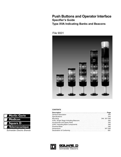
<strong>Push</strong> <strong>Buttons</strong> <strong>and</strong> <strong>Operator</strong> <strong>Interface</strong><br />
Specifier’s Guide<br />
Type XVA Indicating Banks <strong>and</strong> Beacons<br />
File 9001<br />
CONTENTS<br />
Description . . . . . . . . . . . . . . . . . . . . . . . . . . . . . . . . . . . . . . . . . . . . . . . . . . . .Page<br />
General Description . . . . . . . . . . . . . . . . . . . . . . . . . . . . . . . . . . . . . . . . . . . . . . . 344<br />
Specifications . . . . . . . . . . . . . . . . . . . . . . . . . . . . . . . . . . . . . . . . . . . . . . . . . . . .344<br />
Mounting. . . . . . . . . . . . . . . . . . . . . . . . . . . . . . . . . . . . . . . . . . . . . . . . 344, 347-348<br />
XVAL Single Stage Indicating Beacons . . . . . . . . . . . . . . . . . . . . . . . . . . . . . . . .345<br />
Accessories <strong>and</strong> Spare Parts . . . . . . . . . . . . . . . . . . . . . . . . . . . . . . . . . . . . . . . .345<br />
XVAC Indicating Bank Components . . . . . . . . . . . . . . . . . . . . . . . . . . . . . . . . . . .346<br />
Prewired Base . . . . . . . . . . . . . . . . . . . . . . . . . . . . . . . . . . . . . . . . . . . . . . . . . . .346<br />
Dimensions. . . . . . . . . . . . . . . . . . . . . . . . . . . . . . . . . . . . . . . . . . . . . . . . . . 347-348<br />
Declaration of Conformity . . . . . . . . . . . . . . . . . . . . . . . . . . . . . . . . . . . . . . . . . . 350
<strong>Push</strong> <strong>Buttons</strong> <strong>and</strong> <strong>Operator</strong> <strong>Interface</strong> Specifiers Guide<br />
Type XVA — Indicating Banks <strong>and</strong> Beacons<br />
General Description<br />
344<br />
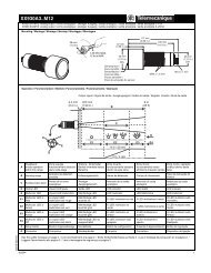
The XVA indicating bank is an illuminated<br />
stackable modular system of signaling lights<br />
that can be used for indicating the status of a<br />
machine <strong>and</strong> verifying that status from a distance<br />
<strong>and</strong> in all directions (360°). The modular<br />
system of lenses allows the unit to be constructed<br />
from any combination of 1 to 5 lenses. Constant,<br />
flashing <strong>and</strong> strobe units are available.<br />
Examples: Indicates machine shutdown, shortage<br />
of materials, paging of supervisor or maintenance<br />
personnel, hazardous or dangerous<br />
conditions to name a few. It is a perfect solution<br />
for status indication on factory floors utilizing<br />
JIT methods.<br />
Machines, instrument panels <strong>and</strong> work stations<br />
equipped with the XVA allow personnel to react<br />
more quickly to any situation or incident.<br />
Limited Availability<br />
For replacement use only.<br />
For new applications, use<br />
XVB (page 223 - 232)<br />
Some industries that currently use or could use XVAs:<br />
Automotives Canning<br />
OEMs Test Equipment<br />
Electronics Computer Industry<br />
Garment Food Processing<br />
Pharmaceuticals Robotics<br />
Publishing Semiconductor<br />
Textiles<br />
Agriculture<br />
Machine Tool<br />
Typical applications for the XVA include:<br />
Conveyor Systems Industrial Baking Ovens<br />
Machine Tools Automated Paint Booths<br />
Printing Presses Automated Test Equipment<br />
Retro-fit Just-In-Time Manufacturing<br />
Assembly Lines Automated Manufacturing Lines<br />
Textile Looms Assembly Work Stations<br />
Specifications<br />
• One complete single stage beacon or components consisting<br />
of 1 to 5 lenses forming an indicating bank.<br />
• Five colors to select from: green, red, orange, blue <strong>and</strong><br />
clear.<br />
• Signal can be continuous, flashing or strobe.<br />
• Visible from a distance <strong>and</strong> on a 360° radius.<br />
• Shock <strong>and</strong> vibration resistant.<br />
• One common base for 1-5 lenses, only one cable entry<br />
required.<br />
• Aluminum tubes of 4 in. (100 mm), 16 in. (400 mm), <strong>and</strong><br />
31.5 in. (800 mm) lengths for extension of column.<br />
• Audible signal available<br />
Protective treatment St<strong>and</strong>ard version, treatment TC “all climates”<br />
Ambient temperature<br />
Storage: -40 °F to +158 °F (-40 °C to +70 °C)<br />
Operating: -13 °F to +158 °F (-25 °C to +70 °C)<br />
Degree of protection<br />
Approval per UL508. Meets NEMA / UL Type 1 <strong>and</strong> 12<br />
protection, IEC Type IP54<br />
Material<br />
Mounting<br />
• Two screws affix base when units are direct mounted or<br />
four screws used for tube <strong>and</strong> tulip mounted.<br />
• The tube <strong>and</strong> base of column mount directly on the tulip.<br />
• All wiring done into saddle clamp screws in the base.<br />
See page 347 for wiring diagram.<br />
• Lenses stack on one another by use of a captive screw<br />
through the lens.<br />
Specifications<br />
Rated insulation voltage 250 V<br />
Approvals<br />
Lamps<br />
© 1999 - 2000 Schneider Electric All Rights Reserved<br />
Cover <strong>and</strong> lenses: polycarbonate<br />
Base: Polyamide<br />
Tube: Anodized aluminum<br />
Gasket: Neoprene<br />
File E164353<br />
CCN NKCR<br />
File LR 44087<br />
Class 3211 03 <strong>and</strong><br />
Class 3211 07<br />
Marking<br />
5 W minimum, 7W maximum, length:<br />
1.61" (41 mm) for DL1BA●●● 1.93" (49 mm) for DL1BL●●●<br />
Terminal marking Terminal marked “O” common to 5 elements <strong>and</strong> ground<br />
Wiring<br />
®<br />
Captive terminal with screw saddle clamp,<br />
minimum capacity:2 size #18 AWG series<br />
maximum capacity: 2 size #12 AWG series<br />
11/00
XVAL471<br />
(One circuit only)<br />
11/00<br />
XVAC02, 027<br />
XVAC03, 037<br />
XVAC04, 047<br />
XVAC09<br />
DL1B●●●●<br />
XVACO5 XVAC06<br />
XVAC12<br />
(1) XVAC211<br />
Base + cover<br />
XVAC01<br />
XVAC11<br />
<strong>Push</strong> <strong>Buttons</strong> <strong>and</strong> <strong>Operator</strong> <strong>Interface</strong> Specifiers Guide<br />
Type XVAL — Indicating Banks <strong>and</strong> Beacons<br />
Single Stage Indicating Beacon<br />
Indicating Beacons<br />
Limited Availability<br />
For replacement use only.<br />
For new applications, use<br />
XVB (page 223 - 232)<br />
For LED lamp options see page 228 (XVB).<br />
© 1999 - 2000 Schneider Electric All Rights Reserved<br />
Description Signal Color Catalog Number<br />
Complete assembly<br />
comprising:<br />
1 cover<br />
1 illuminated lens unit<br />
1 base<br />
Steady light<br />
lamp type BA15d<br />
(not supplied)<br />
ð 240 Vac/dc<br />
St<strong>and</strong>ard flashing light<br />
lamp type BA15d<br />
(not supplied)<br />
24 V - 240 Vac only (±<br />
10%)<br />
Strobe light<br />
(integral discharge tube)<br />
24 Vdc, 260 mA max.<br />
Strobe light<br />
(integral discharge tube)<br />
110-120 Vac, 110 mA<br />
50-60 Hz<br />
Strobe light<br />
(integral discharge tube)<br />
220 Vac (± 10%), 80 mA<br />
50-60 Hz<br />
Green XVAL331<br />
Red XVAL341<br />
Orange XVAL351<br />
Blue XVAL361<br />
Clear XVAL371<br />
Green XVAL431<br />
Red XVAL441<br />
Orange XVAL451<br />
Blue XVAL461<br />
Clear XVAL471<br />
Green XVAL73C024<br />
Red XVAL74C024<br />
Orange XVAL75C024<br />
Blue XVAL76C024<br />
Clear XVAL77C024<br />
Green XVAL73B120<br />
Red XVAL74B120<br />
Orange XVAL75B120<br />
Blue XVAL76B120<br />
Clear XVAL77B120<br />
Green XVAL73A220<br />
Red XVAL74A220<br />
Orange XVAL75A220<br />
Blue XVAL76A220<br />
Clear XVAL77A220<br />
Accessories <strong>and</strong> spare parts for indicating beacons <strong>and</strong> banks<br />
Type<br />
Accessories<br />
for tube<br />
mounting<br />
Gaskets for<br />
use at point<br />
of mounting<br />
Lamps type<br />
BA15d<br />
Size/<br />
Type<br />
Voltage<br />
Catalog<br />
Number<br />
4" metal tubes 100 mm XVAC02<br />
16" metal tubes 400 mm XVAC03<br />
31.5" metal tubes 800 mm XVAC04<br />
4" black anodized metal tubes 100 mm XVAC027<br />
16" black anodized metal tubes 400 mm XVAC037<br />
31.5" black anodized metal tubes 800 mm XVAC047<br />
1/2" NPT conduit adaptor Metallic XVAC00<br />
Tube support/fixing plate - Black Anodized Plastic XVAC01<br />
Tube support/fixing plate - Black Anodized Metallic XVAC11<br />
Wall mounting bracket Metallic XVAC12<br />
For direct base mounting XVAC05<br />
For tube support/mounting plate XVAC06<br />
For between lenses, base, cover - replacement<br />
AC or DC<br />
XVAC09<br />
Length 49 mm (BL)<br />
41 mm (BA)<br />
2.5 W 12 V DL1BA012<br />
4 W 24 V DL1BA024<br />
6.5 W 24 V DL1BL024<br />
4 W 48 V DL1BA048<br />
7 W 110 V DL1BA110<br />
7 W 120 V DL1BL120<br />
5 W 160 V DL1BA160<br />
6 W 260 V DL1BA260<br />
345
<strong>Push</strong> <strong>Buttons</strong> <strong>and</strong> <strong>Operator</strong> <strong>Interface</strong> Specifiers Guide<br />
Type XVAC — Indicating Banks <strong>and</strong> Beacons<br />
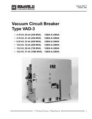
Indicating Bank Components<br />
346<br />
(1) XVAC94<br />
(1) XVAC211<br />
Base + cover<br />
(1) XVAC027<br />
(1) XVAC11<br />
+<br />
(1) XVAC06<br />
+<br />
+<br />
+<br />
(3) DL1BL120<br />
=<br />
+<br />
(1) XVAC341<br />
+<br />
(1) XVAC331<br />
+<br />
1 example<br />
of a complete<br />
indicating bank<br />
(Components for variable composition)<br />
Description Signal Color<br />
Lens unit sub assembly Steady light lamp<br />
type BA15d<br />
(not supplied)<br />
≤ 240 Vac/dc<br />
Limited Availability<br />
For replacement use only.<br />
For new applications, use<br />
XVB (page 223 - 232)<br />
Lens unit sub assembly<br />
with strobe light (only 1<br />
strobe may be used on<br />
each bank <strong>and</strong> must be<br />
mounted in the top<br />
position).<br />
Indicating banks are supplied as sub-assemblies, individually referenced <strong>and</strong> boxed, for assembly<br />
by the user. Maximum number of units: 5, including 1 (max.) top mounted strobe.<br />
See page 345 for Accessories <strong>and</strong> Spare Parts.<br />
▲ Example: XVAC73C024<br />
Pre-Wired Bases (1)<br />
St<strong>and</strong>ard flashing<br />
light lamp<br />
type BA15d<br />
(not supplied)<br />
24 V to 240 Vac<br />
only (± 10%)<br />
Strobe light<br />
(integral discharge<br />
tube)<br />
24 Vdc, 260 mA<br />
max. common<br />
negative (for common<br />
positive, take<br />
off digit 1 at the<br />
end of the reference.<br />
▲<br />
Strobe light<br />
(integral discharge<br />
tube)<br />
110-120 Vac,<br />
110 mA, 50-60 Hz<br />
Strobe light<br />
(integral discharge<br />
tube)<br />
220 Vac (± 10%),<br />
80 mA<br />
50-60 Hz<br />
(1) Common <strong>and</strong> ground wires are provided with all of the above options.<br />
(2) St<strong>and</strong>ard wire provides 2 feet of wire as st<strong>and</strong>ard length.<br />
(3) #14 AWG wire cannot be used with tube support/fixing plates (XVAC01 or XVAC11)<strong>and</strong><br />
wall mounting bracket (XVAC12).<br />
© 1999 - 2000 Schneider Electric All Rights Reserved<br />
Catalog<br />
Number<br />
Green XVAC331<br />
Red XVAC341<br />
Orange XVAC351<br />
Blue XVAC361<br />
Clear XVAC371<br />
Green XVAC431<br />
Red XVAC441<br />
Orange XVAC451<br />
Blue XVAC461<br />
Clear XVAC471<br />
Green XVAC73C0241<br />
Red XVAC74C0241<br />
Orange XVAC75C0241<br />
Blue XVAC76C0241<br />
Clear XVAC77C0241<br />
Green XVAC73B120<br />
Red XVAC74B120<br />
Orange XVAC75B120<br />
Blue XVAC76B120<br />
Clear XVAC77B120<br />
Green XVAC73A220<br />
Red XVAC74A220<br />
Orange XVAC75A220<br />
Blue XVAC76A220<br />
Clear XVAC77A220<br />
Audible sounder sub<br />
assembly (90 db. at<br />
1 meter, 3KHz)<br />
Continuous tone<br />
12 to 48Vdc, 13 mA max.<br />
common negative<br />
110 to 220 Vac, 3.3 mA<br />
XVAC911<br />
XVAC93<br />
(for common positive<br />
remove digit 1 at the end<br />
of the reference<br />
Example: XVAC91)<br />
Intermittent tone<br />
12 to 48 Vdc 13 mA max.<br />
common negative<br />
110 to 220 Vac, 3.1 mA<br />
XVAC921<br />
XVAC94<br />
Cover <strong>and</strong> one to five unit base XVAC211<br />
Cover only XVAC081<br />
Base only XVAC07<br />
Wire Gauge St<strong>and</strong>ard Wire (2)<br />
#14 AWG (3) XVAC211S5<br />
#16 AWG XVAC211S1<br />
#18 AWG XVAC211S10<br />
#22 AWG XVAC211S11<br />
11/00
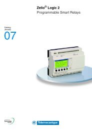
Indicating beacon, 1 stage<br />
= 1.65<br />
42<br />
dia.<br />
2.7<br />
69<br />
=<br />
= 1.65<br />
42<br />
=<br />
dia.<br />
2.7<br />
69<br />
11/00<br />
4.2<br />
107<br />
Indicating bank<br />
Column 1 to 5 stages<br />
b2<br />
2.7<br />
69<br />
dia.<br />
.98<br />
25<br />
= 2.12<br />
54<br />
=<br />
dia.<br />
2.67<br />
68<br />
dia.<br />
.98<br />
25<br />
= 2.12<br />
54<br />
dia.<br />
2.67<br />
68<br />
=<br />
<strong>Push</strong> <strong>Buttons</strong> <strong>and</strong> <strong>Operator</strong> <strong>Interface</strong> Specifiers Guide<br />
Type XVA — Indicating Banks <strong>and</strong> Beacons<br />
Dimensions<br />
4.2<br />
107<br />
b1<br />
.63<br />
16<br />
b2<br />
1.57<br />
40<br />
b1<br />
.63<br />
16<br />
b<br />
Mounting<br />
with tube<br />
b<br />
Mounting<br />
with tube<br />
Tube length<br />
Note: For strobe unit add 3.19" (81mm) to total stack height.<br />
Note: For strobe unit add 3.19" (81 mm) to total stack height.<br />
Limited Availability<br />
For replacement use only.<br />
For new applications, use<br />
XVB (page 223 - 232)<br />
© 1999 - 2000 Schneider Electric All Rights Reserved<br />
b b1<br />
in. mm in. mm in. mm<br />
3.9 100 7.3 186 2.5 63<br />
15.7 400 19.1 486 14.3 363<br />
31.5 800 34.9 886 30.0 763<br />
Cabling<br />
(base viewed from above)<br />
No. of<br />
lenses Tube length b b1 b2<br />
1<br />
2<br />
3<br />
4<br />
5<br />
in. mm in. mm in. mm in. mm<br />
3.9 100 7.3 186 2.5 63 4.2 107<br />
15.7 400 19.1 486 14.3 363 4.2 107<br />
31.5 800 34.9 886 30.0 763 4.2 107<br />
3.9 100 9.25 238 2.5 63 6.25 159<br />
15.7 400 21.2 538 14.3 363 6.25 159<br />
31.5 800 36.9 938 30.0 763 6.25 159<br />
3.9 100 11.4 290 2.5 63 8.3 211<br />
15.7 400 23.2 590 14.3 363 8.3 211<br />
31.5 800 39.0 990 30.0 763 8.3 211<br />
3.9 100 13.4 342 2.5 63 10.3 263<br />
15.7 400 25.3 642 14.3 363 10.3 263<br />
31.5 800 41.0 1042 30.0 763 10.3 263<br />
3.9 100 15.5 394 2.5 63 12.4 315<br />
15.7 400 27.3 694 14.3 363 12.4 315<br />
31.5 800 43.0 1094 30.0 363 12.4 315<br />
Wiring Diagram<br />
L1<br />
1st unit<br />
L2<br />
2nd unit<br />
3rd unit<br />
** “—” pole to “common” terminal<br />
0 (+)<br />
1<br />
2<br />
3<br />
4<br />
5<br />
4th unit<br />
5th unit<br />
Common**<br />
347
<strong>Push</strong> <strong>Buttons</strong> <strong>and</strong> <strong>Operator</strong> <strong>Interface</strong> Specifiers Guide<br />
Type XVA — Indicating Banks <strong>and</strong> Beacons<br />
Dimensions<br />
Baseplate 1<br />
Lite Tube<br />
Wall Mount Front<br />
348<br />
0.40<br />
10.5<br />
0.22<br />
5.5<br />
0.059<br />
r =<br />
1.5<br />
4.02<br />
102<br />
1.50<br />
38<br />
Dia. (Qty. 2)<br />
0.43<br />
11<br />
0.17<br />
4.32<br />
Dia. (Qty. 4)<br />
0.20<br />
5.08<br />
0.17<br />
4.32<br />
40°<br />
0.19<br />
5<br />
0.50<br />
12.7<br />
0.39<br />
r =<br />
10<br />
30°<br />
0.39<br />
10<br />
0.95<br />
24<br />
0.059<br />
r =<br />
1.5<br />
Dia. 0.90<br />
22.86<br />
0.91<br />
23<br />
M23 x 2<br />
2.68<br />
68<br />
0.26<br />
6.60<br />
0.59<br />
15<br />
1.46<br />
37<br />
65°<br />
0.047<br />
@ 45°<br />
1.2<br />
0.55<br />
13.97<br />
0.76<br />
19.30<br />
0.76<br />
19.30<br />
Inches<br />
millimeters<br />
4.50<br />
114.3<br />
0.98<br />
25<br />
Wall Mount Side<br />
2.04<br />
51.82<br />
0.53<br />
13.5<br />
0.53<br />
13.5<br />
0.05<br />
1.27<br />
Wall Mount Bottom<br />
Dia.(Qty.3)<br />
0.23<br />
5.84<br />
1.50<br />
38<br />
0.17<br />
4.32<br />
0.53<br />
13.5<br />
0.46<br />
11.68<br />
0.14<br />
3.56<br />
Dia.<br />
0.15<br />
3.81<br />
Drilling <strong>and</strong> tapping of support<br />
© 1999 - 2000 Schneider Electric All Rights Reserved<br />
2.20<br />
55.88<br />
4.50<br />
114.3<br />
2.68<br />
68<br />
1.20<br />
30.5<br />
0.30<br />
7.62<br />
Tubing <strong>and</strong> Thread Dimensions<br />
Wall Mounting Bracket<br />
To be Drawn<br />
1.65<br />
42<br />
1.33<br />
43<br />
2 size M4 screws<br />
(dia. 4)<br />
Inches<br />
millimeters<br />
0.055<br />
1.4<br />
2 size M5 screws<br />
(dia. 5)<br />
0.055<br />
1.4<br />
0.70<br />
17.8<br />
0.90<br />
22.86<br />
2.12<br />
54<br />
0.20<br />
5.08<br />
0.20<br />
5.08<br />
0.28<br />
7.11<br />
2.04<br />
51.82<br />
0.13<br />
3.30<br />
11/00<br />
1.57<br />
40<br />
2.12<br />
54