You also want an ePaper? Increase the reach of your titles
YUMPU automatically turns print PDFs into web optimized ePapers that Google loves.
<strong>RT</strong> <strong>100</strong> R<br />
The new Ratio drill<br />
with patented point grind<br />
– for the machining of CGI and ADI<br />
– for top performance and cost efficiency
<strong>RT</strong> <strong>100</strong> R for CGI and ADI<br />
New materials require new tooling<br />
solutions. As the global leader in cutting<br />
tool innovation, <strong>Guhring</strong> thrives on every<br />
opportunity to “push the envelope” on<br />
tool performance or to tackle the newest,<br />
most difficult machining challenges. The<br />
increased use of CGI (compacted graphite<br />
iron) and ADI (austempered ductile iron)<br />
in the automotive and other industries<br />
certainly presents such a challenge. Our<br />
answer for CGI and ADI holemaking<br />
applications: our new <strong>RT</strong> <strong>100</strong> R.<br />
High tensile strength materials are<br />
exceptionally demanding<br />
CGI and ADI’s attractiveness stems<br />
from their high tensile strength<br />
combined with light weight.<br />
Regarding engine design, this offers<br />
the opportunity to increase engine<br />
output while maintaining current<br />
engine block wall thickness. Alternatively,<br />
current engine output can be<br />
maintained while reducing engine block<br />
wall thickness and thereby decreasing<br />
engine weight.<br />
The challenge is that these new materials<br />
are extremely hard and abrasive and, as<br />
such, are extremely difficult to machine.<br />
Conventional tools have failed to<br />
deliver satisfactory results in terms of<br />
machining speed, quality and tolerance;<br />
tool life; and, ultimately, cost efficiency.<br />
To fill this void and provide a suitable<br />
holemaking solution for CGI and ADI and<br />
similar materials, <strong>Guhring</strong> developed<br />
the <strong>RT</strong> <strong>100</strong> R coolant-through carbide<br />
drill. Based on our popular <strong>RT</strong> <strong>100</strong> line,<br />
the new drill’s key features include:<br />
• patented radius point geometry<br />
• uniquely balanced face contour and<br />
flute profile,<br />
• in-house developed, ultra wearresistant<br />
DK 255 F carbide substrate,<br />
and<br />
• GUHRING’s proprietary “super<br />
tough” FIREX ® multilayer coating.<br />
Powerful in common cast materials<br />
The new radius point geometry offers<br />
more than machining of CGI and ADI,<br />
the new radius point is also a top choice<br />
for machining common cast materials,<br />
such as gray cast iron, spheroidal<br />
graphite iron and malleable cast iron.<br />
Standard versus Special range<br />
The <strong>RT</strong> <strong>100</strong> R is available as a stocked<br />
standard with coolant-through and<br />
FIREX ® coating, in 5xD and 7xD<br />
lengths, and in many popular fractional<br />
inch and metric diameters from<br />
3.00 mm to 20.00 mm. Alternatively,<br />
a <strong>RT</strong> <strong>100</strong> R can be custom-made with<br />
or without coolant through, with a<br />
different coating, in different lengths<br />
and diameters, and with multiple<br />
cutting diameters to perfectly match<br />
your specific application(s). Please see<br />
the <strong>RT</strong> <strong>100</strong> R Special Tool Request Form<br />
on page 7.<br />
Our recommendation:<br />
The <strong>RT</strong> <strong>100</strong> R drills are well-suited<br />
for machining with minimal quantity<br />
lubrication (MQL) systems. For more<br />
information, please contact our Technical<br />
Service Department.<br />
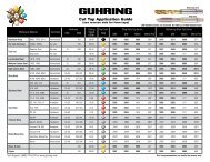
Selected machining results with <strong>RT</strong> <strong>100</strong> R drills<br />
Diameter 16 17<br />
Coating FIREX ® Super A<br />
Material GGG50 GGG40<br />
Drilling depth (mm) 20 50<br />
Cooling IC IC<br />
Lubricant neat oil soluble oil<br />
v c [m/min] 120 160<br />
f [mm/rev.] 0.5 0.6<br />
Tool life [m] 615 305<br />
<br />
<strong>RT</strong> <strong>100</strong> R
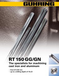
Top performer in key benchmark tests:<br />
Best in tool wear and life<br />
In technical third-party tests performed<br />
by the Technical University of Darmstadt<br />
(PTW Darmstadt – Darmstadt, Germany),<br />
the <strong>RT</strong> <strong>100</strong> R significantly outperformed<br />
all competitors in machining CGI,<br />
registering the lowest tool wear while<br />
scoring the highest tool life.<br />
In the first test, tool wear was<br />
compared by measuring the cutting<br />
edge wear width of 5.00 mm diameter<br />
drills after they had machined 5,000<br />
20 mm-deep holes for a total depth of<br />
<strong>100</strong> m. As shown in Diagram 1 below,<br />
the tool wear of the <strong>RT</strong> <strong>100</strong> R was only<br />
0.196 mm, the lowest figure among the<br />
7 tools tested.<br />
As a key indicator of potential total tool<br />
life, outer corner wear was also measured<br />
(See Diagram 2). Even after 5,000 holes,<br />
the <strong>RT</strong> <strong>100</strong> R registered little corner wear,<br />
suggesting that the tool could be used to<br />
machine considerably more holes.<br />
A second test was conducted to measure<br />
face wear and to confirm total tool life.<br />
For this test, the technicians selected<br />
step drills with an inside cutting diameter<br />
of 14.50 mm and an outside diameter of<br />
20.00 mm with a 45° chamfer at the step.<br />
Based on the results of the first test, a<br />
total tool life of 120 m (approx. 1,715<br />
holes at a depth of 70 mm per hole) was<br />
expected. Not only did the <strong>RT</strong> <strong>100</strong> R<br />
dominate the test, it was well on its<br />
way to doubling the pre-test predictions<br />
when the test was called. At that point,<br />
the <strong>RT</strong> <strong>100</strong> R step drill had cut a total of<br />
3,057 holes, or a total depth of 214 m<br />
(See Figure 3). It displayed a very even<br />
wear pattern, was the only tool whose<br />
coating was still intact at the leading<br />
land, and could have kept on producing<br />
more holes!<br />
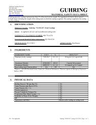
Diagram 1: Cutting edge wear width after drilling total depth of <strong>100</strong> m<br />
workpiece material = GGV40<br />
coolant pressure = 65 bar speed = 80 m/min feed = 0.20 mm/rev.<br />
hole diameter = 5.00 mm hole depth = 20 mm no. of holes = 5,000<br />
Width of wear Vb (mm)<br />
0.55<br />
0.50<br />
0.45<br />
0.40<br />
0.35<br />
0.30<br />
0.25<br />
0.20<br />
0.15<br />
0.10<br />
0.05<br />
0<br />
1<br />
2 3 4 5 6 <strong>RT</strong> <strong>100</strong> R<br />
Competitor<br />
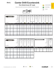
Diagram 3: Face wear and life<br />
workpiece material = GGV40<br />
coolant pressure = 50 bar speed = 70 m/min feed = 0.30 mm/rev.<br />
hole diameters = 14.50 mm x 20.00 mm<br />
hole depth = 70 mm<br />
Development of outer corner wear VB in µm<br />
Diagram 2: Outer corner wear after drilling total depth of <strong>100</strong> m<br />
1.0<br />
Width of wear Vb (mm)<br />
0.9<br />
0.8<br />
0.7<br />
0.6<br />
0.5<br />
0.4<br />
0.3<br />
0.2<br />
0.1<br />
0<br />
Competitor 1<br />
Competitor 2<br />
<strong>RT</strong> <strong>100</strong> R<br />
holes<br />
5000<br />
4500<br />
3900<br />
3300<br />
2700<br />
2<strong>100</strong><br />
1500<br />
900<br />
300<br />
12.7 25.4 38.1 50.8 88.9 114.3 190.5 215.9<br />
Tool life in m<br />
0 <strong>100</strong> 200 300<br />
Wear Vb in mm<br />
<strong>RT</strong> <strong>100</strong> R
<strong>RT</strong> <strong>100</strong> R for CGI and ADI<br />
Tool material<br />
Solid Carbide<br />
Carbide type<br />
K20<br />
Carbide grade DK 255 F<br />
Surface finish FIREX ®<br />
Cooling<br />
Internal<br />
<strong>Guhring</strong> no. 6501<br />
DIN 6537<br />
Shank design DIN 6535 HA<br />
Type Ratio R<br />
Tool material<br />
Solid Carbide<br />
Carbide type<br />
K20<br />
Carbide grade DK 255 F<br />
Surface finish FIREX ®<br />
Cooling<br />
Internal<br />
<strong>Guhring</strong> no. 6501<br />
Tool material<br />
Solid Carbide<br />
Carbide type<br />
K20<br />
Carbide grade DK 255 F<br />
Surface finish FIREX ®<br />
Cooling<br />
Internal<br />
<strong>Guhring</strong> no. 6501<br />
d 1 d 2 l 1 l 2<br />
Dec in Fract in W/L mm mm mm mm<br />
d 1 d 2 l 1 l 2<br />
Dec in Fract in W/L mm mm mm mm<br />
0,45 x d 1<br />
0.2811 9/32 K 7.14 | | | 0.4803 12.20 | | |<br />
0.2323 5.90 | | | 0.4252 10.80 | | |<br />
0.2343 15/64 5.95 | | | 0.4291 10.90 | | |<br />
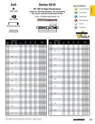
Product information<br />
0.2362 6.00 6.00 82 44 0.4331 11.00 | | |<br />
• drilling depth – 5xD<br />
0.2402 6.10 8.00 91 53 0.4370 11.10 | | |<br />
0.2441 6.20 | | | 0.4374 7/16 11.11 | | |<br />
• righthand cutting<br />
0.2480 6.30 | | | 0.4409 11.20 | | |<br />
0.2500 1/4 E 6.35 | | | 0.4449 11.30 | | |<br />
• patented radius<br />
0.2520 6.40 | | | 0.4488 11.40 | | |<br />
point geometry<br />
0.2559 6.50 | | | 0.4528 11.50 | | |<br />
• 30° flute helix<br />
0.2598 6.60 | | | 0.4567 11.60 | | |<br />
• Cutting dia m7 tolerance<br />
0.2638 6.70 | | | 0.4606 11.70 | | |<br />
0.2657 17/64 H 6.75 | | | 0.4646 11.80 | | |<br />
0.2677 6.80 | | | 0.4685 11.90 | | |<br />
0.2717 I 6.90 | | | 0.4689 15/32 11.91 | | |<br />
0.2756 7.00 | | | 0.4724 12.00 12.00 118 71<br />
0.2795 7.10 | | | 0.4764 12.10 14.00 124 77<br />
0.2835 7.20 | | | 0.4843 31/64 12.30 | | |<br />
l 2<br />
0.2874 7.30 | | | 0.4882 12.40 | | |<br />
l 1<br />
0.2913 7.40 | | | 0.4921 12.50 | | |<br />
0.2953 7.50 | | | 0.4961 12.60 | | |<br />
d 1 d 2 l 1 l 2<br />
0.2969 19/64 7.54 | | | 0.5000 1/2 12.70 | | |<br />
0.2992 7.60 | | | 0.5039 12.80 | | |<br />
Dec in Fract in W/L mm mm mm mm 0.3031 7.70 | | | 0.5079 12.90 | | |<br />
0.1181 3.00 6.00 66 28 0.3071 7.80 | | | 0.5118 13.00 | | |<br />
0.1220 3.10 | | | 0.3110 7.90 | | | 0.5157 33/64 13.10 | | |<br />
0.1248 1/8 3.17 | | | 0.3126 5/16 7.94 | | | 0.5236 13.30 | | |<br />
0.1260 3.20 | | | 0.3150 8.00 8.00 91 53 0.5276 13.40 | | |<br />
0.1280 3.25 | | | 0.3189 8.10 10.00 103 61 0.5315 13.50 | | |<br />
0.1299 3.30 | | | 0.3228 P 8.20 | | | 0.5394 13.70 | | |<br />
0.1339 3.40 | | | 0.3268 8.30 | | | 0.5433 13.80 | | |<br />
0.1378 3.50 | | | 0.3280 21/64 8.33 | | | 0.5472 13.90 | | |<br />
0.1406 9/64 28 3.57 | | | 0.3307 8.40 | | | 0.5512 14.00 14.00 124 77<br />
0.1417 3.60 | | | 0.3346 8.50 | | | 0.5551 14.10 16.00 133 83<br />
0.1457 3.70 | 66 28 0.3386 8.60 | | | 0.5591 14.20 | | |<br />
0.1496 25 3.80 | 74 36 0.3425 8.70 | | | 0.5626 9/16 14.29 | | |<br />
0.1535 3.90 | | | 0.3437 11/32 8.73 | | | 0.5630 14.30 | | |<br />
0.1563 5/32 3.97 | | | 0.3465 8.80 | | | 0.5669 14.40 | | |<br />
0.1575 4.00 | | | 0.3504 8.90 | | | 0.5709 14.50 | | |<br />
0.1614 4.10 | | | 0.3543 9.00 | | | 0.5748 14.60 | | |<br />
0.1654 4.20 | | | 0.3583 9.10 | | | 0.5787 14.70 | | |<br />
0.1693 18 4.30 | | | 0.3594 23/64 9.13 | | | 0.5866 14.90 | | |<br />
0.1720 11/64 4.37 | | | 0.3622 9.20 | | | 0.5906 15.00 | | |<br />
0.1732 4.40 | | | 0.3642 9.25 | | | 0.5945 15.10 | | |<br />
0.1772 16 4.50 | | | 0.3661 9.30 | | | 0.5984 15.20 | | |<br />
0.1811 4.60 | | | 0.3701 9.40 | | | 0.6024 15.30 | | |<br />
0.1831 4.65 | | | 0.3740 9.50 | | | 0.6063 15.40 | | |<br />
0.1850 13 4.70 | 74 36 0.3748 3/8 9.52 | | | 0.6102 15.50 | | |<br />
0.1874 3/16 4.76 | 82 44 0.3780 9.60 | | | 0.6142 15.60 | | |<br />
0.1890 12 4.80 | | | 0.3819 9.70 | | | 0.6181 15.70 | | |<br />
0.1929 4.90 | | | 0.3858 W 9.80 | | | 0.6220 15.80 | | |<br />
0.1969 5.00 | | | 0.3898 9.90 | | | 0.6248 5/8 15.87 | | |<br />
0.2008 5.10 | | | 0.3906 25/64 9.92 | | | 0.6260 15.90 | | |<br />
0.2031 13/64 5.16 | | | 0.3937 10.00 10.00 103 61 0.6299 16.00 16.00 133 83<br />
0.2047 5.20 | | | 0.3976 10.10 12.00 118 71 0.6496 16.50 18.00 143 93<br />
0.2087 5.30 | | | 0.4016 10.20 | | | 0.6563 21/32 16.67 | | |<br />
0.2126 5.40 | | | 0.4055 10.30 | | | 0.6693 17.00 | | |<br />
0.2165 5.50 | | | 0.4063 13/32 10.32 | | | 0.6890 17.50 | | |<br />
0.2185 5.55 | | | 0.4094 10.40 | | | 0.7087 18.00 18.00 143 93<br />
0.2189 7/32 5.56 | | | 0.4134 10.50 | | | 0.7283 18.50 20.00 153 101<br />
0.2205 5.60 | | | 0.4173 10.60 | | | 0.7480 19.00 | | |<br />
0.2244 5.70 | | | 0.4213 10.70 | | | 0.7677 19.50 | | |<br />
0.2283 5.80 6.00 82 44 0.4220 27/64 10.72 | | | 0.7874 20.00 20.00 153 101<br />
d 2<br />
d 1<br />
<br />
<strong>RT</strong> <strong>100</strong> R
Tool material<br />
Solid Carbide Tool material<br />
Solid Carbide Tool material<br />
Solid Carbide<br />
Carbide type<br />
K20 Carbide type<br />
K20 Carbide type<br />
K20<br />
Carbide grade DK 255 F Carbide grade DK 255 F Carbide grade DK 255 F<br />
Surface finish FIREX ® Surface finish FIREX ® Surface finish FIREX ®<br />
Cooling<br />
Internal Cooling<br />
Internal Cooling<br />
Internal<br />
<strong>Guhring</strong> no. 6502 <strong>Guhring</strong> no. 6502 <strong>Guhring</strong> no. 6502<br />
DIN<br />
<strong>Guhring</strong> Std<br />
d 1 d 2 l 1 l 2 d 1 d 2 l 1 l 2<br />
Shank design DIN 6535 HA<br />
Dec in Fract in W/L mm mm mm mm Dec in Fract in W/L mm mm mm mm<br />
Type Ratio R<br />
0.2756 7.00 | | | 0.4724 12.00 12.00 163 114<br />
0,45 x d 1<br />
0.3268 8.30 | | | 0.5433 13.80 | | |<br />
0.2795 7.10 | | | 0.4764 12.10 14.00 182 133<br />
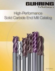
Product information<br />
0.2811 9/32 K 7.14 | | | 0.4803 12.20 | | |<br />
• drilling depth – 7xD<br />
0.2835 7.20 | | | 0.4843 31/64 12.30 | | |<br />
0.2874 7.30 | | | 0.4882 12.40 | | |<br />
• righthand cutting<br />
0.2913 7.40 | | | 0.4921 12.50 | | |<br />
0.2953 7.50 | | | 0.4961 12.60 | | |<br />
• patented radius<br />
0.2969 19/64 7.54 | | | 0.5000 1/2 12.70 | | |<br />
point geometry<br />
0.2992 7.60 | | | 0.5039 12.80 | | |<br />
• 30° flute helix<br />
0.3031 7.70 | | | 0.5079 12.90 | | |<br />
• Cutting dia m7 tolerance<br />
0.3071 7.80 | | | 0.5118 13.00 | | |<br />
0.3110 7.90 | | | 0.5157 33/64 13.10 | | |<br />
0.3126 5/16 7.94 | | | 0.5236 13.30 | | |<br />
0.3150 8.00 8.00 116 76 0.5276 13.40 | | |<br />
0.3189 8.10 10.00 131 87 0.5315 13.50 | | |<br />
0.3228 P 8.20 | | | 0.5394 13.70 | | |<br />
0.3280 21/64 8.33 | | | 0.5472 13.90 | | |<br />
l 2<br />
0.3307 8.40 | | | 0.5512 14.00 14.00 182 133<br />
l 1<br />
0.3346 8.50 | | | 0.5551 14.10 16.00 204 152<br />
0.3386 8.60 | | | 0.5591 14.20 | | |<br />
d 1 d 2 l 1 l 2<br />
0.3425 8.70 | | | 0.5626 9/16 14.29 | | |<br />
0.3437 11/32 8.73 | | | 0.5630 14.30 | | |<br />
Dec in Fract in W/L mm mm mm mm 0.3465 8.80 | | | 0.5669 14.40 | | |<br />
0.1575 4.00 6.00 75 38 0.3504 8.90 | | | 0.5709 14.50 | | |<br />
0.1614 4.10 | | | 0.3543 9.00 | 131 87 0.5748 14.60 | | |<br />
0.1654 4.20 | 75 38 0.3583 9.10 | 139 95 0.5787 14.70 | | |<br />
0.1693 18 4.30 | 85 45 0.3594 23/64 9.13 | | | 0.5866 14.90 | | |<br />
0.1720 11/64 4.37 | | | 0.3622 9.20 | | | 0.5906 15.00 | | |<br />
0.1732 4.40 | | | 0.3642 9.25 | | | 0.5945 15.10 | | |<br />
0.1772 16 4.50 | | | 0.3661 9.30 | | | 0.5984 15.20 | | |<br />
0.1811 4.60 | | | 0.3701 9.40 | | | 0.6024 15.30 | | |<br />
0.1831 4.65 | | | 0.3740 9.50 | | | 0.6063 15.40 | | |<br />
0.1850 13 4.70 | 85 45 0.3748 3/8 9.52 | | | 0.6102 15.50 | | |<br />
0.1874 3/16 4.76 | 90 50 0.3780 9.60 | | | 0.6142 15.60 | | |<br />
0.1890 12 4.80 | | | 0.3819 9.70 | | | 0.6181 15.70 | | |<br />
0.1929 4.90 | | | 0.3858 W 9.80 | | | 0.6220 15.80 | | |<br />
0.1969 5.00 | | | 0.3898 9.90 | | | 0.6248 5/8 15.87 | | |<br />
0.2008 5.10 | | | 0.3906 25/64 9.92 | | | 0.6260 15.90 | | |<br />
0.2031 13/64 5.16 | | | 0.3937 10.00 10.00 139 95 0.6299 16.00 16.00 204 152<br />
0.2047 5.20 | | | 0.3976 10.10 12.00 155 106 0.6496 16.50 18.00 223 171<br />
0.2087 5.30 | 90 50 0.4016 10.20 | | | 0.6563 21/32 16.67 | | |<br />
0.2126 5.40 | 97 57 0.4055 10.30 | | | 0.6693 17.00 | | |<br />
0.2165 5.50 | | | 0.4063 13/32 10.32 | | | 0.6890 17.50 | | |<br />
0.2185 5.55 | | | 0.4094 10.40 | | | 0.7087 18.00 18.00 223 171<br />
0.2189 7/32 5.56 | | | 0.4134 10.50 | | | 0.7283 18.50 20.00 244 190<br />
0.2205 5.60 | | | 0.4173 10.60 | | | 0.7480 19.00 | | |<br />
0.2244 5.70 | | | 0.4213 10.70 | | | 0.7677 19.50 | | |<br />
0.2283 5.80 | | | 0.4220 27/64 10.72 | | | 0.7874 20.00 20.00 244 190<br />
0.2323 5.90 | | | 0.4252 10.80 | | |<br />
0.2343 15/64 5.95 | | | 0.4291 10.90 | | |<br />
0.2362 6.00 6.00 97 57 0.4331 11.00 | 155 106<br />
0.2402 6.10 8.00 106 66 0.4370 11.10 | 163 114<br />
0.2441 6.20 | | | 0.4374 7/16 11.11 | | |<br />
0.2480 6.30 | | | 0.4409 11.20 | | |<br />
0.2500 1/4 E 6.35 | | | 0.4449 11.30 | | |<br />
0.2520 6.40 | | | 0.4488 11.40 | | |<br />
0.2559 6.50 | | | 0.4528 11.50 | | |<br />
0.2598 6.60 | | | 0.4567 11.60 | | |<br />
0.2638 6.70 | | | 0.4606 11.70 | | |<br />
0.2657 17/64 H 6.75 | | | 0.4646 11.80 | | |<br />
0.2677 6.80 | 106 66 0.4685 11.90 | | |<br />
0.2717 I 6.90 | 116 76 0.4689 15/32 11.91 | | |<br />
d 2<br />
d 1<br />
<strong>RT</strong> <strong>100</strong> R
Application recommendations<br />
Prerequisites for the application of <strong>RT</strong>150 GG/GN drills:<br />
• Powerful machines<br />
• No play in spindle bearings<br />
• Alignment-accurate toolholders<br />
(Hydraulic or shrinkfit chucks recommended)<br />
• Max. concentricity error of clamped tools 0.02 mm<br />
• High coolant pressure<br />
Guh.<br />
no.<br />
Tool material<br />
Carbide grade<br />
Surface finish<br />
Cooling<br />
Drilling depth<br />
DIN 6537<br />
<strong>Guhring</strong> std.<br />
Solid carbide<br />
K20<br />
~ 5 x D ~ 7 x D<br />
6501<br />
6502<br />
Coolant hints:<br />
We recommend lubrication by soluble or neat oil. Under<br />
special conditions, air cooling is possible, but cooling by<br />
Minimum Quantity Lubrication is preferred. For optimum performance,<br />
the tools should have conical end shanks and <strong>Guhring</strong> MQL components<br />
should be utilized. Please contact our technical service department for<br />
more information.<br />
CONVERSIONS<br />
SFM = m/min. x 3.28<br />
IPR = mm/rev ÷ 25.4<br />
drill-Ø<br />
mm<br />
2.50<br />
3.15<br />
4.00<br />
5.00<br />
6.30<br />
8.00<br />
10.00<br />
12.50<br />
16.00<br />
20.00<br />
25.00<br />
Feed column no.<br />
1 2 3 4 5 6 7 8 9<br />
f (mm/rev.)<br />
0.025 0.032 0.040 0.050 0.063 0.080 0.<strong>100</strong> 0.125 0.160<br />
0.032 0.040 0.050 0.063 0.080 0.<strong>100</strong> 0.125 0.160 0.160<br />
0.040 0.050 0.063 0.080 0.<strong>100</strong> 0.125 0.160 0.200 0.200<br />
0.040 0.050 0.063 0.080 0.<strong>100</strong> 0.125 0.160 0.200 0.250<br />
0.050 0.063 0.080 0.<strong>100</strong> 0.125 0.160 0.200 0.250 0.315<br />
0.063 0.080 0.<strong>100</strong> 0.125 0.160 0.200 0.250 0.315 0.315<br />
0.080 0.<strong>100</strong> 0.125 0.160 0.200 0.250 0.315 0.400 0.400<br />
0.080 0.<strong>100</strong> 0.125 0.160 0.200 0.250 0.315 0.400 0.500<br />
0.<strong>100</strong> 0.125 0.160 0.200 0.250 0.315 0.400 0.500 0.630<br />
0.125 0.160 0.200 0.250 0.315 0.400 0.500 0.630 0.630<br />
0.160 0.200 0.250 0.315 0.400 0.500 0.630 0.800 0.800<br />
Material<br />
Material example<br />
Figures in bold = material no. to DIN EN 10 027<br />
Tens. strength Hard-<br />
MPa (N/mm 2 ) ness<br />
Common structural steels 1.0035 S185, 1.0486 StE P275N, 1.0345 P235GH, 1.0425 P265GH ≤ 500<br />
1.0050 E295, 1.0070 E360, 1.8937 P500NH > 500-850<br />
Free-cutting steels 1.0718 11SMnPb30, 1.0736 115Mn37 ≤850<br />
1.0727 46 S20, 1.0728 60 S20, 1.0757 46SPb20 850-<strong>100</strong>0<br />
Unalloyed heat-treatable steels<br />
1.0402 C22, 1.1178 C30E ≤700<br />
1.0503 C45, 1.1191 C45E 700-850<br />
1.0601 C60, 1.1221 C60E 850-<strong>100</strong>0<br />
Alloyed heat-treatable steels<br />
1.5131 50MnSi4, 1.7003 38Cr2, 1.7030 28Cr4 850-<strong>100</strong>0<br />
1.5710 36NiCr6, 1.7035 41Cr4, 1.7225 42CrMo4 <strong>100</strong>0-1200<br />
Unalloyed case hardened steels 1.0301 C10, 1.1121 C10E ≤750<br />
Alloyed case hardened steels 1.7043 38Cr4 850-<strong>100</strong>0<br />
1.5752 14NiCr14, 1.7131 16MnCr5, 1.7264 20CrMo5 <strong>100</strong>0-1200<br />
Nitriding steels 1.8504 34CrAl6 850-<strong>100</strong>0<br />
1.8519 31CrMoV9, 1.8550 34CrAlNi7 <strong>100</strong>0-1200<br />
Tool steels 1.1750 C75W, 1.2067 102Cr6, 1.2307 29CrMoV9 ≤850<br />
1.2080 X210Cr12, 1.2083 X42Cr13, 1.2419 105WCr6, 1.2767 X45NiCrMo4 850-<strong>100</strong>0<br />
High speed steels 1.3243 S 6-5-2-5, 1.3343 S 6-5-2, 1.3344 61CrV4 ≥650-<strong>100</strong>0<br />
Spring steels 1.5026 55Si7, 1.7176 55Cr3, 1.8159 51CrV4 ≤330 HB<br />
Stainless steels, sulphured<br />
austenitic<br />
martensitic<br />
1.4005 X12CrS13, 1.4104 X14CrMoS17, 1.4105 X6CrMoS17, 1.4305 X8CrNiS18 9 ≤850<br />
1.4301 X5CrNi18 10, 1.4541 X6CrNiTi18 10, 1.4571 X6CrNiMoTi 17 12 2 ≤850<br />
1.4057 X17CrNi16-1, 1.4122 X39CrMo17-1, 1.4521 X2CrMoTi18 2 ≤850<br />
v c<br />
m/min<br />
Feed column no.<br />
Hardened steels – ≤40-60 HRC<br />
Special alloys Nimonic, Inconel, Monel, Hastelloy ≤1200<br />
Cast iron 0.6010 EN-GJL-<strong>100</strong> (GG10), 0.6020 EN-GJL-200 (GG20) ≤240 HB 210 9 8<br />
0.6025 EN-GJL-250 (GG25), 0.6035 EN-GJL-350 (GG35) 600-850<br />
Bronze, long-chipping 2.0380 CuZn39Pb2, 2.0401 CuZn39Pb3, 2.0410 CuZn43Pb2 ≤850<br />
2.0250 CuZn20, 2.0280 CuZn33, 2.0332 CuZn37Pb0,5 850-<strong>100</strong>0<br />
<br />
<strong>RT</strong> <strong>100</strong> R
<strong>Guhring</strong>, Inc.<br />
Tel (262) 784-6730<br />
Fax (262) 784-9096<br />
Customer no. New customer Order no.<br />
West Coast Sales Office<br />
Tel (714) 841-3582<br />
Fax (714) 841-3592<br />
Company<br />
Street no.<br />
Contact name<br />
City, State & Postal code<br />
Canada Sales Office<br />
Tel (519) 748-9664<br />
Fax (519) 748-2954<br />
Telephone no.<br />
Date<br />
Fax no.<br />
Signature<br />
Solid carbide Ratio drills<br />
<strong>RT</strong> <strong>100</strong> R<br />
Carbide grade<br />
K20<br />
SINGLE DIAMETER<br />
d3<br />
d1<br />
l3<br />
l5<br />
l2<br />
l1<br />
0,45 x d<br />
Relation of nom.-Ø d 1 , shank-Ø d 3 and shank length l 5<br />
nom.-Ø d 1 min/max 4-6 >6-8 >8-10 >10-12 >12-14 >14-16 >16-18 >18-20<br />
shank-Ø d 3<br />
6 8 10 12 14 16 18 20<br />
shank length l 5<br />
36 40 45 48 50<br />
Nom.-Ø d 1<br />
Shank-Ø d 3 to DIN 6535<br />
Shank design to DIN 6535<br />
Drilling depth l 3<br />
Flute length l 2<br />
Total length l 1<br />
Double margins<br />
Cooling<br />
Surface finish/coating<br />
Workpiece material<br />
Quantity<br />
Range<br />
4.0 – 20.0 mm<br />
see table above<br />
HA , HE<br />
max. 7 x D (run out min. 0.01-0.02)<br />
max. 155 mm<br />
56 – 205 mm<br />
yes / no<br />
internal / external / soluble oil / minimal quantity lubrication / dry<br />
bright / F I R E X ® / MolyGlide ® / Super-A<br />
Standard tolerances: nom.-Ø = m7, shank-Ø = h6<br />
Complete<br />
Solid carbide Ratio<br />
drills<br />
<strong>RT</strong> <strong>100</strong> R<br />
Carbide grade<br />
K20<br />
Step-Ø d 1<br />
Step-Ø d 2<br />
Shank-Ø d 3 to DIN 6535<br />
Shank form to DIN 6535<br />
Step length l 4<br />
Drilling depth l 3<br />
Flute length l 2<br />
Total length l 1<br />
Step angle<br />
Double margins<br />
Cooling<br />
Surface finish/coating<br />
Workpiece material<br />
Quantity<br />
MULTIPLE DIAMETERS / STEP<br />
d3<br />
Range<br />
Senkwinkel<br />
l5<br />
4.0 – 20.0 mm<br />
l1<br />
l3<br />
l2<br />
0,45 x d<br />
l4<br />
4.0 – 20.0 mm<br />
see table above<br />
HA , HE<br />
5 – <strong>100</strong> mm<br />
max. 7 x D (run out min. 0.01-0.02)<br />
max. 155 mm<br />
56 – 205 mm<br />
60° / 90° / 120° / 180°<br />
yes / no<br />
internal / external / soluble oil / min. quantity lubrication / dry<br />
bright / F I R E X ® / MolyGlide ® / Super-A<br />
d1<br />
d2<br />
Relation of nom.-Ø d 2 , shank-Ø d 3 and shank length l 5<br />
nom.-Ø d 2 min/max 4-6 >6-8 >8-10 >10-12 >12-14 >14-16 >16-18 >18-20<br />
shank-Ø d 3<br />
6 8 10 12 14 16 18 20<br />
shank length l 5<br />
36 40 45 48 50<br />
Complete<br />
Standard tolerances: step-Ø d 1 = m7; body-Ø d 2 = h7; shank-Ø d 3 = h6<br />
<strong>RT</strong> <strong>100</strong> R
<strong>Guhring</strong>, Inc.<br />
P.O. Box 643, Brookfield, WI 53008-0643<br />
Shipping Address<br />
<strong>Guhring</strong> Corporation<br />
1445 Commerce Avenue 20 Steckle Place, Unit #14<br />
Brookfield, WI 53045<br />
Kitchener, ON N2E 2C3<br />
Tel (262) 784-6730 (800) 776-6170 Tel (519) 748-9664 (800) 877-7202<br />
Fax (262) 784-9096 Fax (519) 748-2954<br />
West Coast Distribution Center<br />
16291 Gothard Street<br />
Huntington Beach, CA 92647<br />
Tel (714) 841-3582 (800) 877-7202<br />
Fax (714) 841-3592<br />
Our product range:<br />
1. Drilling Tools<br />
in High Speed Steel and Carbide<br />
Twist drills<br />
Ratio drills<br />
Micro-precision drills<br />
Oil feed drills<br />
Subland drills<br />
Center drills<br />
Core drills<br />
Gun drills<br />
NC spot drills<br />
2. Thread Cutting Tools<br />
in High Speed Steel and Carbide<br />
Hand taps<br />
Machine taps and fluteless taps<br />
Oil feed taps and oil feed fluteless taps<br />
Thread milling cutters<br />
Dies<br />
3. Milling Cutters<br />
in High Speed Steel and Carbide<br />
Ratio end mills<br />
Slot drills<br />
End mills<br />
Radius profile cutters<br />
Hard profile cutters<br />
Diesinking cutters<br />
4. Reaming Tools<br />
in High Speed Steel and Carbide<br />
HSS and HSS-E reamers<br />
Carbide reamers<br />
Taper pin reamers<br />
Hand reamers<br />
5. Countersinking Tools<br />
in High Speed Steel and Carbide<br />
Countersinks, counterbores and spot facers<br />
Short counterbores<br />
Back spot facers<br />
6. Cutting Tools<br />
in ultra-hard materials<br />
Cermet and ceramic tools<br />
PCD- and PCB-tipped tools<br />
7. Coated Tools<br />
A-tools, TiAlN coated<br />
C-tools, TiCN coated<br />
F-tools, FIREX ® coated<br />
S-tools, TiN coated<br />
M-tools, MolyGlide ® coated<br />
Super A (AlTiN) coated<br />
8. Modular Tooling Systems<br />
Tooling system GM 300<br />
for rotary and stationary tools, offering a large<br />
combination of toolholding possibilities<br />
Flexible tooling system GE <strong>100</strong><br />
a tooling system for the combined machining<br />
operations facing, chamfering, boring, centering etc.<br />
Cartridge tooling system DP 200<br />
with indexable inserts for roughing and finishing<br />
operations in complex workpieces<br />
9. Special Tools<br />
to sketch or drawing, the more complex, the better<br />
10. Carbides<br />
for precision cutting tools, for metal forming<br />
and punching tools<br />
11. Tungsten Carbide Forming Tools<br />
for the production of nuts and bolts<br />
Cold forming tools<br />
Heading die inserts<br />
Punching pins<br />
12. HSC Motor Spindles,<br />
Hydro expansion chucks,<br />
Shrinkfit chucks and systems<br />
13. Tool Restoration Service<br />
Regrinding, recoating, tool management<br />
© <strong>Guhring</strong>, Inc. 2006 FORM 01-6501 (5/06)