Smiths H-1000 Fluid Warmer Service Manual - internetMED
Smiths H-1000 Fluid Warmer Service Manual - internetMED
Smiths H-1000 Fluid Warmer Service Manual - internetMED

You also want an ePaper? Increase the reach of your titles
YUMPU automatically turns print PDFs into web optimized ePapers that Google loves.
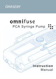
OPERATOR’S AND SERVICE MANUAL<br />
-<br />
Level 1 ® H-<strong>1000</strong><br />
<strong>Fluid</strong> <strong>Warmer</strong><br />
H-<strong>1000</strong> 100V<br />
Manufacturer:<br />
<strong>Smiths</strong> Medical ASD, Inc.<br />
160 Weymouth Street<br />
Rockland, MA 02370, USA<br />
USA/Canada: 1-800-258-5361<br />
International: +1-781-878-8011<br />
www.smiths-medical.com<br />
Made in U.S. A.<br />
P/N 4533801 Rev. 001
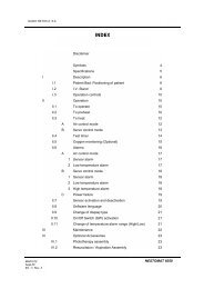
Level 1 ® H-<strong>1000</strong> Operator's & <strong>Service</strong> <strong>Manual</strong><br />
About This <strong>Manual</strong> 2<br />
Purpose 2<br />
Concept 2<br />
System Features 3<br />
Filter with Gas Vent 3<br />
Temperature Control 4<br />
Flanking I.V. Pole Brackets 4<br />
Unpacking and Set up 4<br />
System <strong>1000</strong> Hardware 6<br />
Power and Alarm Test Panel 6<br />
Display Panel 7<br />
Interlocks 8<br />
Accessories: System 1025 Pressure Infusers 9<br />
Set-up and Use 9<br />
Disposables: Set up and Performance 12<br />
Setting Up Disposable Sets 12<br />
Priming Disposable Sets 13<br />
Filter with Gas Vent Replacement in IV Disposable Sets 13<br />
Trouble Shooting 15<br />
Trouble Shooting Slow Flow Rates 16<br />
Testing 17<br />
Add Water Alarm 17<br />
Check Disposables Alarm 17<br />
Water Over Temperature Alarm 18<br />
Alarm Testing 18<br />
Performance Testing 18<br />
Earth Leakage 19<br />
Ground Continuity 19<br />
Dialectric Strength 20<br />
Maintenance 20<br />
Maintenance and Testing Log 22<br />
<strong>Service</strong> 22<br />
Warranty <strong>Service</strong> 22<br />
Non-Warranty <strong>Service</strong> 24<br />
Specifications 24<br />
Physical Specifications 24<br />
Electrical and Environmental Specifications 24<br />
Accessory, Maintenance and Calibration Part Numbers 25<br />
Parts and Electrical Schematics 25<br />
International Symbols 28<br />
No part of this manual may be reproduced in any form without prior written permission from <strong>Smiths</strong> Medical ASD, Inc.<br />
(<strong>Smiths</strong> Medical)<br />
Level 1 and <strong>Smiths</strong> design mark are trademarks of the <strong>Smiths</strong> Medical family of companies. The symbol ® indicates the<br />
trademark is registered in the U.S. Patent and Trademark office and certain other countries.<br />
*Cover pictures the H-1025, a combination of the H-<strong>1000</strong> <strong>Fluid</strong> <strong>Warmer</strong> and two accessory H-2 Pressure Infusion Chambers.<br />
The products described are covered by one or more of the following U.S. Patent Nos. 4,759,749; 4,878,537; 4,900,308;<br />
5,063,994; 5,097,898; and 4,678,460; other patent(s) pending.<br />
© 2006 <strong>Smiths</strong> Medical family of companies. All rights reserved.<br />
Operator’s <strong>Manual</strong> Part #4533801 (Rev 001) 2006/08
About This <strong>Manual</strong><br />
These instructions contain important information for safe use of the product. Read the<br />
entire operator's manual, including Warnings and Cautions, before using the<br />
Level 1 ® H-<strong>1000</strong> <strong>Fluid</strong> <strong>Warmer</strong>. Failure to properly follow warnings, cautions, and<br />
instructions could result in death or serious injury to the patient.<br />
! WARNING !<br />
Messages that are headed by "! WARNING !" indicate information or procedures that if not<br />
followed correctly can cause improper results, damage to the equipment, injury to<br />
personnel, or patient death.<br />
Messages that are headed by "CAUTION:" indicate information or procedures that if not<br />
followed correctly can cause improper results and damage to the equipment.<br />
Messages that are headed by "NOTE:" indicate information or procedures that if not<br />
followed correctly can cause improper results.<br />
Purpose<br />
The Level 1 ® H-<strong>1000</strong> fluid warmer has been designed for safe, rapid in-line warming of I.V.<br />
fluids as they are administered to patients. Disposable sets designed for warming at<br />
various infusion rates are available. Blood and I.V. solutions may be infused through the<br />
Level 1 ® I.V. Sets, and will be delivered near 40 °C.<br />
High flow capacity, warm fluid delivery, simple operation, and continuous on-board safety<br />
systems make the H-<strong>1000</strong> the ideal choice for all procedures requiring routine to rapid<br />
infusion of normothermic fluids. Typical uses of the system include blood and solution<br />
warming during elective surgery, in the I.C.U., the Emergency Room and in Trauma.<br />
Concept<br />
The H-<strong>1000</strong> fluid warmer consists of a reusable hardware device and a single-use<br />
disposable set. Similar to extracorporeal warming technology found in the heart room,<br />
warmed water is rapidly circulated through a disposable anodized aluminum tube to warm<br />
fluids as they are delivered to the patient. The use of a thermal conductor, rapid warm<br />
water circulation, and counter-current flow all contribute to the high warming capacity of<br />
the H-<strong>1000</strong>.<br />
2
Circulating<br />
water bath<br />
flow<br />
Heat<br />
Exchanger<br />
Heater<br />
Pump<br />
Figure 1. Block diagram of Level 1 ® fluid warmers.<br />
Figure 1 diagrams the H-<strong>1000</strong> and its operation.<br />
An onboard pump circulates warm water through<br />
the aluminum heat exchanger in the disposable<br />
set. Note that the circulating water bath and the<br />
infusate flow against each other, or countercurrent,<br />
which maximizes heat transfer. This<br />
diagram describes the essence of all Level 1 ® fluid<br />
warmers.<br />
System features<br />
Filter with Gas Vent<br />
Level 1 ® D-Series Disposable Sets employ a unique "hands-off" Gas Vent which vents<br />
micro-bubbles of gas that are always released from fluids as they are warmed. In many<br />
other warming systems, these micro-bubbles are actually delivered to the patient along<br />
with the warmed fluids.<br />
The Filter with Gas Vent assembly in the I.V. Sets contains a 170-micron screen filter to<br />
trap macro-aggregates found in blood products. This filter has luer-lock connections and<br />
3
can be easily changed without patient disconnection or repriming of the entire disposable<br />
set. The Filter with Gas Vent should be changed every three hours or when the filter<br />
becomes clogged, whichever comes first.<br />
Temperature control<br />
The H-<strong>1000</strong> employs a safe circulating water heating system, inherently free of any "hot<br />
spots." The primary temperature control circuit sets the circulating water bath to a<br />
temperature of approximately 42 °C for efficient heat exchange and maximum fluid<br />
warming.<br />
Flanking I.V. Pole Brackets<br />
The sturdy design of the H-<strong>1000</strong> offers a compact, custom I.V. pole mount set up. This<br />
versatile workstation features flanking side poles for Level 1 ® pressure infusers, syringe<br />
pumps or infusion pumps.<br />
Unpacking and Set up<br />
The H-<strong>1000</strong> packaging should contain the following items:<br />
Contents<br />
Quantity<br />
H-<strong>1000</strong> Warming Unit 1<br />
H-<strong>1000</strong> I.V. Pole Base 1<br />
H-<strong>1000</strong> I.V. Bag Hanger 1<br />
H-<strong>1000</strong> I.V. Pole with Flanking Brackets 1<br />
Accessory Pack:<br />
H-<strong>1000</strong> <strong>Manual</strong> 1<br />
D-Series Instruction Card 1<br />
Y-Connector 1<br />
Black Pneumatic Tubing 1<br />
Hex Wrench 1<br />
1. Place the base upright on its wheels. Lock casters to prevent pole movement during<br />
set up.<br />
2. Remove the three threaded pole screws on the vertical base tube. Slide the I.V. pole<br />
with flanking brackets down over the vertical base tube lining up the three screw holes in<br />
the pole with the three screw holes in the base as shown in Figure 2. Note: the flanking<br />
brackets should face the longer side of the base.<br />
3. Thread the three pole screws back through the holes at the base of the pole and<br />
tighten.<br />
4. Attach the H-<strong>1000</strong> warming unit to the flanking brackets by sliding the eight threaded<br />
screws on the back of the unit into the eight keyhole notches on the flanking I.V. pole<br />
brackets. (Refer to Figure 2.) Tighten all eight screws to secure warmer to I.V. pole and<br />
flanking brackets.<br />
5. Lock I.V. bag hanger into place on the top of the I.V. pole.<br />
4
6. Close the drain valve (seen in Figure 7) on the bottom of the unit. Remove the fill port<br />
plug on the front of the unit and fill the tank with 1.4 liters of distilled water. Replace the fill<br />
port plug.<br />
Figure 2. H-<strong>1000</strong> assembly<br />
CAUTION: Tap water will increase earth leakage current. For proper system operation and<br />
component life, use only DISTILLED WATER in the water reservoir.<br />
7. Plug the unit into the appropriate electrical outlet. (See specifications for details. )<br />
5
CAUTION: This device must be assembled and tested by <strong>Smiths</strong> Medical technical<br />
personnel, an authorized distributor of <strong>Smiths</strong> Medical or a trained biomedical engineer<br />
prior to placing the device into service. Refer to the Testing section of this manual for<br />
complete system testing instruction.<br />
H-<strong>1000</strong> Hardware<br />
The H-<strong>1000</strong> has an onboard water supply heated to 41.7 °C. This temperature controlled<br />
water supply is rapidly circulated through the heat exchanger of the disposable set. Two<br />
independent circuits continuously control and monitor water temperature, and will shut the<br />
system down and alarm in the event of an over temperature condition.<br />
Power and Alarm Testing<br />
The power and alarm test panel on the front of the H-<strong>1000</strong> cabinet is shown in Figure 3<br />
below. It contains four membrane switches. Only a gentle press is required to activate<br />
each switch.<br />
1. POWER ON<br />
The green switch on the left powers ON the H-<strong>1000</strong> warming unit including the onboard<br />
compressor for the pressure infuser accessory system.<br />
2. POWER OFF<br />
The orange switch on the right powers OFF the unit.<br />
3. ALARM TEST<br />
This alarm test button confirms proper operation of visual and audible alarm systems.<br />
Press and hold this button to test alarm systems. When the switch is released the WATER<br />
OVER TEMPERATURE alarm will continue to sound. This is normal operation. To clear<br />
the alarm condition, turn the unit OFF and then back ON.<br />
4. OVER TEMPERATURE TEST<br />
This alarm test button confirms proper operation of the OVER TEMPERATURE circuitry.<br />
6
Press and hold this button to test this alarm circuitry. When the switch is released the<br />
WATER OVER TEMPERATURE alarm will continue to sound. This is normal operation.<br />
To clear this alarm condition, turn the unit OFF and then back ON.<br />
Figure 3. Power and Alarm Panel<br />
Figure 4. Display Panel<br />
41<br />
1.4 Liters<br />
H 2 O<br />
Display Panel<br />
The display panel shown in Figure 4 contains visual information that continuously<br />
indicates the status of the H-<strong>1000</strong> during operation. Five displays provide information for<br />
safe, convenient use of the device.<br />
1. CIRCULATING WATER BATH TEMPERATURE<br />
Displays temperature of the circulating water bath in °C. This is not the temperature of the<br />
fluid delivered to the patient.<br />
2. SYSTEM OPERATIONAL<br />
This GREEN indicator illuminates when the power switch is ON and the heat exchanger<br />
has been properly installed.<br />
7
3. CHECK DISPOSABLES<br />
This Yellow indicator and pulsing AUDIBLE ALARM indicate the heat exchanger is NOT<br />
properly installed.<br />
4. ADD WATER<br />
This Yellow indicator and pulsing AUDIBLE ALARM indicate additional distilled water must<br />
be added to the water reservoir.<br />
5. WATER OVER TEMPERATURE<br />
This RED indicator and AUDIBLE ALARM indicate an over temperature condition. Press<br />
and hold this switch to confirm proper operation of the OVER TEMP circuitry.<br />
NOTE: When any one or more of the alarms are activated, and the red and/or yellow<br />
indicators are illuminated, and the audible alarm is sounding, no water is circulating and<br />
no fluid warming is taking place.<br />
Interlocks<br />
Three low voltage interlocks are located in the cabinet. They sense the presence of a<br />
properly installed heat exchanger and filter with gas vent. These interlocks prevent the<br />
pump from pumping water when there is no disposable in place to complete the circulation<br />
loop. If the "CHECK DISPOSABLE" alarm is activated and the light next to the "2" socket<br />
is illuminated, press the #2 socket down firmly to engage the interlock switch.<br />
The H-<strong>1000</strong> display panel provides information for safe, convenient set up and use of the<br />
device.<br />
8
Accessories: H-1025 Pressure Infusers<br />
The H-<strong>1000</strong> is equipped with an onboard compressor that is used to operate two Level 1 ®<br />
pressure infusion chambers (H-2’s). Pressure Infusion chambers are sold separately as an<br />
accessory to the H-<strong>1000</strong>. The H-<strong>1000</strong> combined with two pressure infusion chambers is<br />
referred to as the H-1025. Pressure Infusers are not required to operate the H-<strong>1000</strong>, but<br />
are a valuable accessory to complete this total fluid management system.<br />
H-1025 pressure infusers provide controlled, convenient pressurization of I.V. blood and<br />
fluid bags for rapid administration of fluids. These automated pressure chambers quickly<br />
reach and hold a preset pressure of 300 mmHg for high speed fluid delivery not possible<br />
with manually pumped pressure cuffs. The factory set 300 mmHg pressure is constant<br />
and not adjustable. At 300 mmHG pressure, flow rates may be altered by adjusting the<br />
roller clamp on the Level 1 ® D-series disposable I.V. fluid warming set.<br />
With the H-1025 infusion chambers, pressure can be applied or released with the throw of<br />
a switch. Empty I.V. fluid bags can be de-pressurized, replaced and repressurized in<br />
seconds. Each pressure infuser contains an expansion bladder to accommodate either a<br />
500 ml bag or a <strong>1000</strong> ml bag. And a safety relief valve is also contained in each chamber<br />
to help prevent over-pressurizing fluid bags.<br />
If you have purchased a pair of pressure infusion chambers, please refer to the following<br />
pressure infuser set up instructions for proper installation.<br />
Packaging for each pair of H-1025 pressure infusers should contain the following items:<br />
Contents<br />
Quantity<br />
H-2 Pressure Infuser 2<br />
Y-Connector 1<br />
Black Tubing 1<br />
Set-up and Use<br />
CAUTION: This device must be assembled and tested by <strong>Smiths</strong> Medical technical<br />
personnel, an authorized distributor of <strong>Smiths</strong> Medical or a trained biomedical engineer<br />
prior to placing the device in service.<br />
! WARNING !: Level 1 ® pressure chambers are to be used only as a component of the<br />
Level 1 ® fluid warmer. Do not connect to compressed gas bottles, O.R. Air, or any other<br />
pneumatic pressure source. Be sure that the chrome poles on the H-<strong>1000</strong> are in the<br />
upright position.<br />
1. Loosen the two pole mounting thumb screws on the back of one H-2 pressure chamber<br />
as seen in Figure 5. Slide the H-2 over the top of the flanking bracket.<br />
9
2. Secure the H-2 in<br />
place by tightening the<br />
two pole mounting<br />
screws.<br />
3. Repeat steps 1 and 2<br />
for the second H-2<br />
pressure chamber.<br />
Mounting Screws<br />
Chrome Pole<br />
Y-Connector<br />
Remove Plug and<br />
insert black tubing<br />
Figure 5. Installing Pressure Infusers<br />
4. Remove the orange<br />
plug from the red ring<br />
connector located on the<br />
back of the H-<strong>1000</strong>. This<br />
is done by depressing the<br />
red plastic ring and<br />
pulling the plug out.<br />
5. Press the piece of<br />
black pneumatic tubing<br />
firmly into the connector<br />
on the back of the H-<br />
<strong>1000</strong> until it bottoms out.<br />
Press the other end of<br />
the tubing into bottom of<br />
the Y-connector.<br />
6. Press the black tube<br />
from one of the H-2s into<br />
the Y-connector. Press<br />
the black tube from the<br />
other H-2 into the Y-<br />
connector.<br />
Once the H-<strong>1000</strong> is turned on, 300 mmHg pressure can be automatically applied by<br />
pushing the toggle switch on the top front of the H-2 chamber all the way over to the "+"<br />
or ON position. Always make sure that the chamber door is closed and latched when<br />
pressure is activated.<br />
With the Level 1 ® pressure infusion chambers properly installed, the H-<strong>1000</strong> fluid warmer<br />
becomes the H-1025, a complete fluid management system.<br />
10
To Load<br />
In order to help avoid inadvertent infusion of air to the patient the following warnings<br />
should be observed:<br />
! WARNING !<br />
Remove all air from solution bags.<br />
! WARNING !<br />
Not for use with commercial I.V. solution bags less than 1 liter with air.<br />
! WARNING !<br />
Not for use with autotransfusion bags.<br />
1. Set up and prime Level 1 ® D-Series disposable I.V. fluid warming set following the<br />
instructions on disposable package.<br />
2. Flip toggle switch on top front of the H-2 chamber all the way over to the "-" or OFF<br />
position.<br />
3. Open chamber door by swinging out hinged latch on right side.<br />
4. Hang air-free solution bag on door post.<br />
NOTE: Each pressure chamber can hold either a 500 ml bag or a <strong>1000</strong> ml bag. For a 500<br />
ml bag, the hanging post is located on the inside of the door. For a <strong>1000</strong> ml bag, the post<br />
is located on the top of the door. For optimum drainage of 1 liter bags, the upper molded<br />
post is for longer style bags. The lower molded post is used for standard size bags.<br />
5. Close door and secure side latch.<br />
To Pressurize<br />
CAUTION: Be certain latch is secure before chamber is pressurized. Never pressurize with<br />
door open.<br />
CAUTION: Do not exceed 300 mmHg.<br />
1. Push toggle switch all the way over to "+" or ON position. Observe pressure gauge to<br />
ensure 300 mmHg (approx.) is achieved.<br />
NOTE: The pressure is not adjustable on this device. The fluid warmer power switch must<br />
be ON for pressure chambers to operate.<br />
To Unload<br />
1. Push toggle switch all the way over to the "-" or OFF position. This will release pressure<br />
in the chamber and deflate bladder.<br />
2. Open door and remove fluid bag.<br />
11
NOTE: Chamber pressure must be released before the pressure chamber door can be<br />
opened.<br />
To Clean<br />
Please refer to the maintenance section of this manual for complete cleaning and<br />
disinfecting procedures for the H-1025 pressure infusers.<br />
Disposables: Set up and Performance<br />
! WARNING !<br />
Refer to D-series disposable packaging for complete set up and priming instructions,<br />
indications, contraindications, warnings, cautions and additional product information.<br />
Setting Up Disposable Sets<br />
Level 1 ® D-series disposable sets have been designed to be highly effective and easy to<br />
use in combination with the H-<strong>1000</strong> fluid warming hardware. By following the simple 1-2-3<br />
blocks found on the H-<strong>1000</strong> fluid warmer, properly trained users can confidently have the<br />
system safely set up and operating within seconds.<br />
Following the numbers found on the H-<strong>1000</strong>:<br />
1. Push the bottom end of the heat exchanger into the bottom heat exchanger #1 socket.<br />
Be sure the heat exchanger is fully seated.<br />
! WARNING !<br />
Do not bend heat exchanger. Bending the heat exchanger may damage the inner<br />
aluminum tube. If the tube is bent, serious patient injury or death could result.<br />
2. Slide the top (#2) socket up. Snap the heat exchanger into the heat exchanger guide.<br />
Be sure it is fully seated. Slide the top heat exchanger socket down over the heat<br />
exchanger tube.<br />
3. Insert the Filter with Gas Vent into the #3 holder on the front of the cabinet.<br />
4. Press the green power switch on the front of the cabinet to turn ON the unit and allow it<br />
to reach operating temperature while the disposable set is being primed. It takes<br />
between 3 and 7 minutes for the water in the H-<strong>1000</strong> to reach operating temperature.<br />
12
When the H-<strong>1000</strong> is plugged in and turned ON and the disposable set is correctly<br />
installed, a green"OPERATING" light will illuminate and the water temperature will begin<br />
to increase on the display panel. If the disposable set is incorrectly installed and the unit is<br />
turned ON, the yellow "CHECK DISPOSABLE" light will illuminate and an intermittent<br />
alarm will sound.<br />
Priming Disposable Sets<br />
! WARNING !<br />
Set up, priming and use require aseptic technique. Follow applicable hospital policy and<br />
procedures.<br />
! WARNING !<br />
Remove all air from fluid bags before spiking with D-series disposable set.<br />
! WARNING !<br />
All air must be removed from fluid lines prior to patient connection. Failure to do so could<br />
result in the introduction of air to the patient.<br />
! WARNING !<br />
Monitor fluid lines to ensure they are air-free. Never infuse fluids if there are bubbles in<br />
the line between the filter chamber and patient connection.<br />
1. CLOSE the Y-Set clamps.<br />
2. Remove one bag spike cap and spike it into an air-free fluid bag with a twisting motion.<br />
3. Hang the fluid bag from the adjustable I.V. pole and open the lead clamp to the I.V.<br />
bag.<br />
4. Squeeze the drip chamber to the I.V. bag so it is 1/3 to 1/2 full.<br />
5. Remove the male luer cap on the patient line and open the Y-set clamps to the I.V.<br />
bag.<br />
6. Close the patient line clamp when the disposable set is completely primed. The filter<br />
with gas vent will self prime.<br />
7. Gently tap the filter with gas vent against the cabinet to release all trapped air. Priming<br />
is complete. Make patient connection without entrapping air.<br />
8. Adjust flow rate using roller clamp.<br />
Filter with Gas Vent Replacement in I.V. Disposable Sets<br />
Replace the filter with gas vent every THREE HOURS or when the filter becomes clogged<br />
or air is slowly vented. Replace with Level 1 ® product number F-10 or F-30. Refer to<br />
disposable packaging for appropriate filter replacement product number.<br />
13
! WARNING !<br />
Replacement filter with gas vent must be fully primed before continuing infusion.<br />
Thoroughly check patient line for air bubbles before opening roller clamp. If air bubbles<br />
are present, disconnect from the patient and re-prime before continuing infusion.<br />
1. Close all clamps on the D-series disposable set and on new filter with gas vent.<br />
2. Remove the used filter with gas vent from the holder while still connected to the<br />
disposable set.<br />
3. Install the new filter assembly into the #3 holder.<br />
4. Using aseptic technique, disconnect upper luer-lock fitting and, after removing upper<br />
male luer end cap from the new filter, connect the set to the new filter inlet.<br />
5. Holding the used filter horizontally, disconnect the lower patient line luer-lock. Connect<br />
the used filter luer-lock fittings together and discard.<br />
6. With the filter outlet tube clamped, open the clamps above the filter. The filter with gas<br />
vent will self prime.<br />
7. Slowly release the outlet tube clamp and allow the outlet tube to fill completely.<br />
8. Remove the second luer-lock end cap and connect the outlet tube luer-lock to patient<br />
line.<br />
9. Remove the filter with gas vent from its holder and tap it against the cabinet several<br />
times until all trapped air bubbles have been vented out. Return the filter to its holder.<br />
Note: The "CHECK DISPOSABLE" alarm will be activated whenever the filter with gas vent<br />
assembly is removed from its #3 holder.<br />
14
PROBLEM<br />
No Power<br />
Check Disposables Alarm<br />
Add Water Alarm<br />
Water Over Temperature Alarm<br />
Hot cabinet<br />
Difficult to Install Heat Exchanger<br />
Trouble Shooting<br />
THINGS TO CHECK<br />
Make sure that the unit is plugged in and the<br />
power switch is ON.<br />
Is it plugged into correct circuit?<br />
Make sure the heat exchanger and filter are<br />
properly installed and the top (#2) socket is<br />
down. If the top (#2) socket is not properly<br />
seated, the yellow light next to it will illuminate.<br />
Make sure that the water tank is filled above<br />
the minimum mark level. Fill or top off the tank<br />
with DISTILLED water only.<br />
Turn off the power switch to clear the alarm.<br />
Turn on the power switch again. If the unit<br />
continues to alarm, remove it from service for<br />
repair.<br />
Make sure that the air inlet on the bottom of<br />
the unit is not blocked or clogged with dust.<br />
Lubricate the O-Rings in heat exchanger (#1)<br />
and (#2) sockets with silicone. Order Part #<br />
80-04-002 to replace O-Rings.<br />
15
Trouble Shooting Slow Flow Rates<br />
Many factors which are insignificant in low fluid administration are restrictors<br />
of higher flow infusion. If you encounter flow restriction with any Level 1 ® <strong>Fluid</strong><br />
<strong>Warmer</strong>, CHECK EACH OF THESE POSSIBLE CAUSES.<br />
OLD BLOOD<br />
Stored blood begins to develop particulate within 5 to 7 days. This may<br />
partially block fluid pathways, impeding flow.<br />
FULLY SPIKED BAG<br />
Bag port membranes may only be split, not completely pierced.<br />
BAG PORT FILTER (if used)<br />
40 micron to 80 micron filters used between the blood bag and the bag spike<br />
of the Disposable set may restrict flow because:<br />
1. Cold, viscous blood does not flow well through small pore filters.<br />
2. As they are directly connected to the source of particulate with no prefiltering,<br />
they clog quickly.<br />
3. They may trap air which can block filter media surface area.<br />
CLAMPS PARTLY ENGAGED<br />
Check to be sure all clamps are fully open.<br />
TUBE SET<br />
Leaving clamps engaged for extended periods of time when the Disposable<br />
Set is not in use (such as pre-set-up) will cause the tubing to take a SET in<br />
the clamped position.<br />
TUBE KINK<br />
Be sure no tube kinks are present anywhere in the set, especially in the Y-set<br />
when a pressure cuff is employed and the IV Pole is used in a lowered<br />
position.<br />
TRAPPED AIR IN FILTER<br />
As noted in the Priming instructions, remove the Filter from the holder and tap<br />
against the Cabinet to dislodge air bubbles and allow them to vent out.<br />
CLOGGED FILTER<br />
If good quality blood is used, this filter should never cause flow restriction. In<br />
the event of a clogged filter, this component may be changed. If frequent<br />
clogging is encountered, discuss the QUALITY of the blood being used with<br />
your Blood Bank<br />
EXTENSION LINES<br />
Use only extension lines with a bore of .130" (3.3 mm) or larger, equipped<br />
with large bore fittings, such as Level 1 ® Part No’s. X-36 or Y-30.<br />
STOPCOCK OR Y ADAPTER<br />
Any fittings attached to the male luer-lock at the end of the Patient Line<br />
should have large bores. If their bores are smaller than the male luer-lock<br />
bore, they are restrictors.<br />
NEEDLE or CATHETER<br />
If possible, use a minimum 18 Gauge needle or 16 French catheter. Smaller<br />
sizes will reduce flow.<br />
16
Testing<br />
The H-<strong>1000</strong> is equipped with disposable set sensing interlocks. To operate the device and<br />
perform testing operations a Level 1 ® non-sterile, not for patient use D-series disposable<br />
set with heat exchanger and filter assembly must be in place.<br />
! WARNING ! Do not attempt to defeat the disposable sensing interlocks or try to<br />
operate the H-<strong>1000</strong> without a disposable in place. Water may spill from the unit if the<br />
interlocks are defeated.<br />
CAUTION: Prior to placing the H-<strong>1000</strong> into service, the device must be tested by <strong>Smiths</strong><br />
Medical technical personnel, an authorized distributor of <strong>Smiths</strong> Medical or a trained<br />
biomedical engineer. Periodic testing and maintenance should be performed by a<br />
biomedical engineer or trained personnel.<br />
NOTE: Refer to Maintenance and Testing Log section of this manual for safety testing<br />
frequencies and intervals.<br />
Add Water Alarm<br />
The H-<strong>1000</strong> is equipped with a float switch which senses the water level in the onboard<br />
reservoir. When the water level is too low, a yellow indicator on the display panel<br />
illuminates and an audible alarm sounds. In the alarm condition the pump will not circulate<br />
water.<br />
With a test disposable set in place, the ADD WATER alarm may be tested by turning the<br />
drain valve on the bottom of the unit 90 degrees clockwise and allowing water to drain out<br />
into a container. Drain until the water level falls below the minimum mark on the water<br />
tank.<br />
Check Disposables Alarm<br />
Three interlocks sense a properly installed heat exchanger. If a heat exchanger is not in<br />
place and the power switch is ON, a yellow indicator will illuminate and an audible alarm<br />
will sound. With the unit running, the interlocks may be tested one at a time by following<br />
these simple steps.<br />
1. Top Heat Exchanger Socket<br />
Slide up slowly, two yellow indicators will illuminate and the audible alarm will sound.<br />
2. Heat exchanger interlock<br />
Gently pull on the middle of the heat exchanger, one yellow indicator will illuminate and<br />
the audible alarm will sound.<br />
3. Filter holder interlock<br />
Remove the Filter with Gas Vent, one yellow indicator will illuminate and the audible alarm<br />
will sound.<br />
17
Water Over Temperature Alarm<br />
Press and hold the Water Over Temperature alarm test button on the power and test panel<br />
on the front of the unit. The display will jump to 45 °C (as long as the button is pressed<br />
on), and the red over temperature indicator will illuminate and the audible alarm will start to<br />
pulse.<br />
NOTE: The Water Over Temperature Alarm test button actually tests the over temperature<br />
circuitry of the system, not just the visible red display indicator and the audible alarm.<br />
NOTE: Pressing the Water Over Temperature test button or the Alarm test button will disable the<br />
H-<strong>1000</strong> even after the buttons have been released. The unit must be shut off and then re-started to<br />
clear the alarm condition.<br />
Alarm Testing<br />
The audible alarm and all indicator lights may be tested by pressing the Alarm test button<br />
on the power and test panel on the front of the cabinet.<br />
NOTE: Pressing the Alarm test button or the Water Over Temperature test button will disable the<br />
H-<strong>1000</strong> even after the buttons have been released. The unit must be shut off and then re-started to<br />
clear the alarm condition.<br />
Performance Testing<br />
Periodic testing of the overall operating efficiency of the H-<strong>1000</strong> can be accomplished in<br />
one of two simple ways:<br />
1. COLD START TEST<br />
NOTE: This performance test requires a non-sterile, not for patient use Level 1 ® D-series<br />
disposable set to be installed properly on the H-<strong>1000</strong>.<br />
Store the H-<strong>1000</strong> unit in a room where the room temperature is approximately 21 °C<br />
(70 °F). With a non-sterile D-series disposable set in place, note the time, and then turn<br />
the power switch ON. The green "OPERATING" indicator will illuminate. Rapidly rising<br />
numbers will appear on the circulating water bath temperature display. A 41 °C<br />
temperature reading will appear in approximately 3 to 7 minutes on an efficiently operating<br />
unit.<br />
NOTE: If the H-<strong>1000</strong> does not pass the cold start test, it should be returned to <strong>Smiths</strong><br />
Medical or an authorized distributor of <strong>Smiths</strong> Medical for service. Do not attempt to<br />
change the calibration settings.<br />
2. THERMAL CALIBRATION WELL (TCW)<br />
Available from <strong>Smiths</strong> Medical, a TCW may also be used to test performance and confirm<br />
proper calibration of the water bath temperature.<br />
18
NOTE: Use of the TCW requires a digital thermometer NIST traceable and accurate to within<br />
0.1 °C.<br />
Required probe size:<br />
0.099" OD maximum (0.25 cm)<br />
0.50" - 1.50" long (1.27 - 3.81cm)<br />
A short procedure to verify the displayed circulating water bath temperature is as follows:<br />
1. Install TCW in machine in normal heat exchanger position (Socket #s 1 & 2) and<br />
install a test filter assembly at holder (#3).<br />
2. Turn the machine on and allow to warm up for 20 minutes. Insert thermometer<br />
probe fully into well and allow display to stabilize. Compare temperatures.<br />
3. The H-<strong>1000</strong> display will be within 0.3 °C of the thermometer display on a correctly<br />
calibrated unit.<br />
Examples:<br />
a. If the thermometer reads 41.4 °C and the H-<strong>1000</strong> is within the range of<br />
41.1 °C - 41.7 °C, performance is acceptable.<br />
b. If the thermometer reads 42.0 °C and the H-<strong>1000</strong> is within the range of<br />
41.7 °C - 42.3 °C, performance is acceptable.<br />
NOTE: If the system does not conform to within these specifications, it should be returned to<br />
<strong>Smiths</strong> Medical or an authorized distributor of <strong>Smiths</strong> Medical for service.<br />
3. D-SERIES CALIBRATION THERMOMETER (”TempCheck”)<br />
Available from <strong>Smiths</strong> Medical, the TempCheck device may also be used to test<br />
performance and confirm proper calibration of the water bath temperature.<br />
The D-series TempCheck device accurately verifies the temperature of the H-<strong>1000</strong><br />
circulating water bath. It plugs into the auxiliary outlet on the bottom of the H-<strong>1000</strong> and<br />
does not require a separate NIST traceable digital thermometer for operation.<br />
Earth leakage<br />
The H-<strong>1000</strong> must be tested according to IEC 601-1 clause 19. Earth leakage current<br />
testing should be performed with the immersion heater circuit in the full ON condition. In<br />
order to be sure the heater circuit is in a full ON condition, testing should be performed on<br />
units which have been allowed to stand at room temperature, and have room temperature<br />
water in the water reservoir before the unit is turned ON. The H-<strong>1000</strong> warms up quickly,<br />
test readings must be taken within 1 minute of startup.<br />
A steel stud is positioned on the back of the unit for earth leakage testing. Units not<br />
meeting this standard should be returned to <strong>Smiths</strong> Medical or an authorized distributor of<br />
<strong>Smiths</strong> Medical for service.<br />
19
Ground continuity<br />
The H-<strong>1000</strong> must be tested according to IEC 601-1 clause 18. A steel stud is positioned<br />
on the back of the unit for ground continuity testing. Units not meeting this standard<br />
should be returned to <strong>Smiths</strong> Medical or an authorized distributor of <strong>Smiths</strong> Medical for<br />
service.<br />
Dielectric strength<br />
The H-<strong>1000</strong> must be tested according to IEC 601-1 clause 20. Units not meeting this<br />
standard should be returned to <strong>Smiths</strong> Medical or an authorized distributor of <strong>Smiths</strong><br />
Medical for service.<br />
Maintenance<br />
CAUTION: Periodic maintenance and testing should be performed by a bio-medical<br />
engineer or trained personnel.<br />
NOTE: Refer to Maintenance and Testing Log section of this manual for maintenance and<br />
safety testing frequencies and intervals.<br />
EVERY USE:<br />
1. CLEAN EXTERIOR<br />
Clean the entire H-<strong>1000</strong>, or H-1025 with a spray of warm soapy water solution or a<br />
commercial non-abrasive cleaner and a soft cloth after every use. Cold sterilizing<br />
solutions may be used, but strong chemical concentrations may discolor some of the<br />
plastics on the device. Do not use cleaning agents containing abrasives.<br />
NOTE: The H-2 pressure chambers can be partially disassembled for cleaning if needed.<br />
a. To remove the door, open the door and push the door up to compress the spring and<br />
lift bottom end of door out of he slot.<br />
b. To remove the latching hinge, open the latch and pop out of the slot.<br />
c. To remove the air bladder, pull top of bladder away from housing. The bladder is<br />
attached with velcro. Disconnect the pneumatic fittings attached to the bladder valves. To<br />
disconnect the fittings depress the ring closest to the bladder. The bladder is now<br />
disconnected from the housing. Ensure the fitting and attached air lines remain<br />
accessible.<br />
d. To reassemble latch, place the latch evenly into the slot, then pop latch into place.<br />
e. To reassemble door, slide hinge pin at top of door into the hole until spring is fully<br />
compressed. Next, slide bottom hinge pin of door into the hole of channel.<br />
f. To replace the air bladder, press the large bladder valve into the 1/2" straight union<br />
pneumatic fitting, and the tubing attached to the small bladder valve, into the 1/4" straight<br />
union pneumatic fitting. Tuck the fittings inside of the enclosure. Align bladder with the<br />
pressure chamber depression and press to engage the mating velcro strips.<br />
20
For external disinfecting, a 10% bleach/distilled water solution may be used.<br />
CAUTION: Do not autoclave.<br />
Do not use alcohol, abrasive cleaning agents, or solvents.<br />
Do not immerse any part of the H-1025 in liquids.<br />
2. GENERAL INSPECTION<br />
Visually check the condition of the device. Remove any unit from service which shows<br />
physical damage or one in which the test disposable set does not install easily.<br />
EVERY 30 DAYS<br />
1. CHANGE DISTILLED WATER<br />
Drain the water by turning the drain valve shown in Figure 6 clockwise 90 degrees. Drain<br />
until the tank is completely empty. Close the drain valve, remove the fill port plug on the<br />
front of the cabinet and refill the water reservoir with distilled water.<br />
Replace the fill port plug.<br />
Drain Valve<br />
Fan Guard<br />
Auxiliary Outlet<br />
Figure 6. Bottom view of H<strong>1000</strong>. Shows location of Drain valve, Fan filter (guard), and<br />
Auxiliary outlet.<br />
2. LUBRICATE O-RINGS<br />
Place a small amount of silicone lubricant on a cotton swab or the end of a finger and<br />
apply all around the O-Rings in the bottom and top heat exchanger sockets. It is not<br />
necessary to disassemble the sockets to lubricate them.<br />
21
EVERY 12 MONTHS:<br />
1. REPLACE O-RINGS<br />
Remove the O-Rings by pulling them out of the bottom and top sockets with a pair of<br />
needle nose pliers or by prying them out with a small screwdriver. Lubricate the new O-<br />
Rings and then press them into place.<br />
2. CLEAN FAN FILTER<br />
Remove the fan filter with a screwdriver from the bottom of the unit and clean with warm<br />
soapy water.<br />
Maintenance and Testing Log<br />
All maintenance and testing should be done by qualified personnel.<br />
Every 30 days:<br />
Change Distilled water<br />
Lubricate O-Rings<br />
Test alarm switch<br />
Every 12 months:<br />
Replace O-Rings<br />
Clean Fan Filter<br />
Test Add Water Alarm<br />
Test Disposable Alarm<br />
Test Over Temp Alarm<br />
Performance Test/<br />
Verify Temperature<br />
Calibration<br />
Earth Leakage<br />
Ground Continuity<br />
Dialectric Strength<br />
<strong>Service</strong><br />
ALL SERVICE MUST BE PERFORMED BY SMITHS MEDICAL OR ITS AUTHORIZED<br />
AGENTS. SERVICE BY OTHERS VOIDS THE WARRANTY AND TRANSFERS<br />
LIABILITY FOR MALFUNCTIONS OF THE DEVICE TO THE SERVICING<br />
ORGANIZATION.<br />
Warranty <strong>Service</strong><br />
Units received for repair which have not been obviously abused or impact damaged and<br />
are still under warranty will be promptly repaired and returned at no charge. Contact your<br />
22
authorized distributor or the <strong>Smiths</strong> Medical <strong>Service</strong> Department before shipping the unit<br />
to <strong>Smiths</strong> Medical for repair. The <strong>Service</strong> Department will issue a Return Goods<br />
Authorization Number (RGA #). The <strong>Service</strong> Department will need the SERIAL NUMBER<br />
of your unit and a description of the problem.<br />
This Level 1 ® <strong>Fluid</strong> <strong>Warmer</strong> is warranted by <strong>Smiths</strong> Medical ASD Inc. (<strong>Smiths</strong> Medical) to<br />
be free of material and workmanship defects for a period of 1 year (12 months) from the<br />
date of purchase, abuse and impact damage excluded. <strong>Smiths</strong> Medical reserves the right<br />
to replace any or all components in lieu of repair. During the period this warranty is in<br />
effect, any Level 1 ® H-<strong>1000</strong>/H-1025 <strong>Fluid</strong> <strong>Warmer</strong> found to be defective and shipped to<br />
<strong>Smiths</strong> Medical, shipping costs prepaid, will be repaired or replaced. This warranty does<br />
not cover misuse, impact damage or obvious abuse of the device. No warranty or<br />
affirmation of fact, expressed or implied, other than stated above, is made or authorized<br />
by <strong>Smiths</strong> Medical, and <strong>Smiths</strong> Medical's liability in all events is limited to the purchase<br />
price paid for the device.<br />
NOTE: Federal (U.S.A.) Law requires contaminated Medical Equipment to be cleaned and<br />
disinfected before shipment. If this is not done your unit will be immediately returned as it<br />
is received. Be sure that ALL water is drained from the unit before packing and shipping.<br />
FOR QUESTIONS, CONTACT YOUR AUTHORIZED DISTRIBUTOR OR THE SMITHS<br />
MEDICAL SERVICE DEPARTMENT at +1-781-878-8011. Be sure that all of the following<br />
information is included: hospital name, address, telephone number, contact person, serial<br />
number of the device and the apparent problem.<br />
For <strong>Service</strong>, contact your <strong>Smiths</strong> Medical distributor or the <strong>Smiths</strong> Medical Technical<br />
<strong>Service</strong> Department at:<br />
USA/Canada<br />
<strong>Smiths</strong> Medical ASD, Inc.<br />
160 Weymouth Street<br />
Rockland, MA 02370 USA<br />
USA/Canada 1-800-258-5361<br />
International +1-781-878-8011<br />
www.smiths-medical.com<br />
23
NOTE: Please write the RGA# on the outside of the shipping box.<br />
Non-Warranty <strong>Service</strong><br />
Units received which have suffered obvious abuse or impact damage and units no longer<br />
under Warranty will be promptly inspected and a written estimate of repair costs will be<br />
sent or faxed. A purchase order will be required from the hospital consistent with the<br />
written estimate.<br />
SERIAL NUMBER LABEL<br />
Units returned for warranty service must have serial numbers intact. Those with missing or<br />
altered serial numbers will be serviced as non-warranty repairs.<br />
PROMPT DISPOSITION<br />
<strong>Smiths</strong> Medical will make every effort for prompt correction or other adjustment with<br />
respect to any product which proves to be defective.<br />
Specifications<br />
If any electromagnetic or other interference between devices is found during normal use,<br />
please notify your local authorized distributor or <strong>Smiths</strong> Medical for assistance. This<br />
equipment is not suitable for use in the presence of a flammable anesthetic mixture with<br />
air or with oxygen or nitrous oxide. Additional circuit diagrams and information are<br />
available upon request.<br />
This device complies to:<br />
EN 60601-1<br />
EN 60601-1-2<br />
Mode of operation:<br />
Continuous<br />
Degree of protection<br />
against ingress of water:<br />
IPX 1<br />
Type of protection against<br />
electric shock:<br />
Class I<br />
Degree of protection against<br />
electric shock:<br />
Type BF<br />
Physical Specifications<br />
Length, overall 48 inches (122cm)<br />
Width, overall 13 inches (33cm)<br />
Depth, overall 10 inches (26cm)<br />
Weight, assembled, dry 20 pounds (9kG)<br />
Distilled water capacity 0.37 Gal (1.4L)<br />
Air source pressure 300 mmHg<br />
24
Electrical Specifications<br />
Input Voltage<br />
100 VAC<br />
Operating Frequency 50-60 HZ<br />
Operating Current<br />
12 Amps<br />
Auxiliary outlet<br />
1.5 Amps<br />
Temperature Set Point 41.7 °C ± 0.3 °C<br />
Over Temperature Set Point 43.9 °C ± 0.1 °C<br />
Environmental Specifications<br />
Temperature Humidity<br />
Operation 10 °C - 45 °C 30%-75%<br />
Transport 0 °C - 70 °C 30%-75%<br />
Storage 0 °C - 70 °C 30%-75%<br />
This product may be a potential biohazard. Handle and dispose of in accordance with<br />
accepted medical practice and applicable regulations.<br />
Accessories and replacement parts<br />
H-2 Pressure Infusers 7204012<br />
O-Ring kit 8004003<br />
Thermal Calibration Well 8003002<br />
D-Series Calibration Thermometer<br />
(D-Series TempCheck DSTA-40) 8001040<br />
Parts and Electrical Schematics<br />
H-<strong>1000</strong> Electrical Parts List is provided on the pages that follow and electrical Schematics<br />
are provided on pages 30 to 33. Questions or requests for additional information may be<br />
faxed to your authorized distributor or the <strong>Smiths</strong> Medical Technical <strong>Service</strong> Department<br />
at +1-781-878-8201 (U.S.A.) or by calling <strong>Smiths</strong> Medical Technical <strong>Service</strong> Department<br />
at +1-781-878-8011 (U.S.A.).<br />
Any service performed on this unit not authorized by <strong>Smiths</strong> Medical technical personnel<br />
or by an authorized distributor of <strong>Smiths</strong> Medical, will void the warranty and transfer the<br />
liability for any malfunction to the servicing organization. <strong>Smiths</strong> Medical reserves the right<br />
to make changes, without further notice, to any products herein to improve the reliability,<br />
function, or design.<br />
25
Electrical Parts List<br />
Schematic Symbol Ordering Part Description Part Number<br />
26
Electrical Parts List<br />
Schematic Symbol Ordering Part Description Part Number<br />
27
International Symbols<br />
CIRCULATING WATER BATH TEMPERATURE<br />
Displays temperature of the circulating water bath in °C. This is not the<br />
temperature of the fluid delivered to the patient.<br />
SYSTEM OPERATIONAL<br />
This GREEN indicator illuminates when the power switch is ON and the heat<br />
exchanger has been properly installed.<br />
CHECK DISPOSABLES<br />
This Yellow indicator and pulsing AUDIBLE ALARM indicate the heat<br />
exchanger is NOT properly installed. There is also a RED indicator next to<br />
the top socket that illuminates if the #2 socket is not seated properly.<br />
ADD WATER<br />
This Yellow indicator and pulsing AUDIBLE ALARM indicate additional<br />
distilled water must be added to the water reservoir.<br />
WATER OVER TEMPERATURE<br />
This RED indicator and AUDIBLE ALARM indicate an over temperature<br />
condition. Press and hold this switch to confirm proper operation of the<br />
OVER TEMP circuitry.<br />
ALARM TEST<br />
Press and hold this button to confirm proper operation of alarm systems.<br />
When the switch is released, the OVER TEMP will continue to sound. This<br />
is normal operation. To clear the alarm condition, turn the unit off and then<br />
back on.<br />
OFF<br />
Only for a part of EQUIPMENT, Mains are still connected<br />
ON<br />
Only for a part of EQUIPMENT, Mains are connected<br />
Earth Potential<br />
IPX1<br />
Protected against dripping water<br />
Type BF<br />
Equipotentiality<br />
This symbol is located next to the ground stud on the back of the unit<br />
28
Attention, consult accompanying documents.<br />
Collect separately for electrical and electronic equipment.<br />
NOTES:<br />
29